WO2024194940A1 - 制御装置、制御方法、およびプログラム - Google Patents
制御装置、制御方法、およびプログラム Download PDFInfo
- Publication number
- WO2024194940A1 WO2024194940A1 PCT/JP2023/010663 JP2023010663W WO2024194940A1 WO 2024194940 A1 WO2024194940 A1 WO 2024194940A1 JP 2023010663 W JP2023010663 W JP 2023010663W WO 2024194940 A1 WO2024194940 A1 WO 2024194940A1
- Authority
- WO
- WIPO (PCT)
- Prior art keywords
- user
- target position
- moving body
- moving
- control device
- Prior art date
- Legal status (The legal status is an assumption and is not a legal conclusion. Google has not performed a legal analysis and makes no representation as to the accuracy of the status listed.)
- Ceased
Links
Images




Classifications
-
- G—PHYSICS
- G05—CONTROLLING; REGULATING
- G05D—SYSTEMS FOR CONTROLLING OR REGULATING NON-ELECTRIC VARIABLES
- G05D1/00—Control of position, course, altitude or attitude of land, water, air or space vehicles, e.g. using automatic pilots
- G05D1/20—Control system inputs
- G05D1/24—Arrangements for determining position or orientation
- G05D1/243—Means capturing signals occurring naturally from the environment, e.g. ambient optical, acoustic, gravitational or magnetic signals
-
- G—PHYSICS
- G05—CONTROLLING; REGULATING
- G05D—SYSTEMS FOR CONTROLLING OR REGULATING NON-ELECTRIC VARIABLES
- G05D1/00—Control of position, course, altitude or attitude of land, water, air or space vehicles, e.g. using automatic pilots
- G05D1/60—Intended control result
- G05D1/656—Interaction with payloads or external entities
- G05D1/686—Maintaining a relative position with respect to moving targets, e.g. following animals or humans
-
- G—PHYSICS
- G05—CONTROLLING; REGULATING
- G05D—SYSTEMS FOR CONTROLLING OR REGULATING NON-ELECTRIC VARIABLES
- G05D2105/00—Specific applications of the controlled vehicles
- G05D2105/30—Specific applications of the controlled vehicles for social or care-giving applications
- G05D2105/315—Specific applications of the controlled vehicles for social or care-giving applications for guiding or for guest attention
-
- G—PHYSICS
- G05—CONTROLLING; REGULATING
- G05D—SYSTEMS FOR CONTROLLING OR REGULATING NON-ELECTRIC VARIABLES
- G05D2107/00—Specific environments of the controlled vehicles
- G05D2107/60—Open buildings, e.g. offices, hospitals, shopping areas or universities
- G05D2107/67—Shopping areas
-
- G—PHYSICS
- G05—CONTROLLING; REGULATING
- G05D—SYSTEMS FOR CONTROLLING OR REGULATING NON-ELECTRIC VARIABLES
- G05D2109/00—Types of controlled vehicles
- G05D2109/10—Land vehicles
-
- G—PHYSICS
- G05—CONTROLLING; REGULATING
- G05D—SYSTEMS FOR CONTROLLING OR REGULATING NON-ELECTRIC VARIABLES
- G05D2111/00—Details of signals used for control of position, course, altitude or attitude of land, water, air or space vehicles
- G05D2111/10—Optical signals
Definitions
- the present invention relates to a control device, a control method, and a program.
- Patent Document 1 discloses a technology that determines the course of an autonomous moving device to move in parallel with a subject to be followed when a sign of a course change of the subject to be followed is detected.
- Patent Document 1 The technology described in Patent Document 1 relates to controlling a moving object to run parallel to a target to be followed.
- the conventional technology did not take into consideration controlling a moving object to lead a user such as a pedestrian (i.e., to take into account the moving direction of the user and run ahead of the user in the moving direction).
- the present invention was made in consideration of these circumstances, and one of its objectives is to provide a control device, control method, and program that can appropriately control a moving object to lead the user.
- a mobile body control device is a control device for a mobile body that at least temporarily leads a user, and includes an information acquisition unit that acquires information regarding the user's direction of movement, an area setting unit that sets a specified area based on the mobile body, and a target position determination unit that determines a target position to which the mobile body is heading based on the direction of movement and the specified area.
- the predetermined area is a circle or an ellipse.
- the target position determination unit determines the intersection of a straight line that passes through the user and follows the direction of movement and the specified area as the target position.
- the target position determination unit determines the intersection farthest from the user in the direction of movement as the target position.
- the area setting unit changes the parameters that define the specified area depending on the appearance or movement speed of the user.
- the area setting unit changes the parameters that define the specified area in response to an input by the user.
- the area setting unit changes the parameters that define the specified area depending on the degree of congestion of the traveling environment in which the moving body travels.
- a mobile object control device controls a mobile object that at least temporarily leads a user, acquires information about the user's moving direction, sets a predetermined area based on the mobile object, determines a target position to which the mobile object is headed based on the moving direction and the predetermined area, and controls a drive unit attached to the mobile object so that the mobile object moves to the target position.
- a program causes a control device of a moving object that at least temporarily leads a user to obtain information regarding the direction of movement of the user, set a predetermined area based on the moving object, determine a target position to which the moving object is heading based on the moving direction and the predetermined area, and control a drive device attached to the moving object so that the moving object moves to the target position.
- the moving object can be appropriately controlled to lead the user.
- the moving object can transition to being led by the user by repeatedly executing a predetermined process.
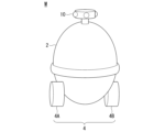
- FIG. 1 is a diagram showing an example of a moving body M equipped with a control device 100 according to an embodiment.
- 2 is a diagram showing an example of a functional configuration of a moving body M.
- FIG. FIG. 4 is a diagram showing an example of a screen displayed by the HMI 30. 13 is a diagram for explaining a method for discretizing the moving direction of a user U.
- FIG. 1 is a diagram showing an example of a predetermined region R set by a region setting unit 120.
- FIG. 13 is a diagram showing an example of another situation in which the predetermined region R is set by the region setting unit 120.
- FIG. 13 is a diagram showing an example of another situation in which the predetermined region R is set by the region setting unit 120.
- FIG. 13 is a diagram showing an example of another situation in which the predetermined region R is set by the region setting unit 120.
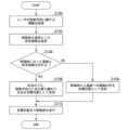
- FIG. 4 is a flowchart showing an example of a flow of processing executed by the control device 100.
- FIG. 1 is a diagram showing an example of a moving body M equipped with a control device according to an embodiment.
- the moving body M is an autonomous mobile robot.
- the moving body M supports the actions of a user U. For example, the moving body M stops at a position designated by the user U, and guides the user U to the destination after receiving an input of the destination, or leads the user U (i.e., travels ahead of the user U in the moving direction) based on information regarding the moving direction of the user U without receiving an input of the destination.
- the moving body M is described as guiding or leading the user U as a pedestrian, but the moving body M may be one that the user U can ride in, and in that case, it may be one that moves to the destination with the user U on board after receiving an input of the destination by the user U.
- FIG. 2 is a diagram showing an example of the functional configuration of a moving body M.
- the moving body M includes, for example, a camera 10, a communication device 20, an HMI 30, a moving body sensor 40, a position identification device 50, a control device 100, and a driving device 200.
- Camera 10 captures the surroundings of moving body M.
- Camera 10 is, for example, a fisheye camera capable of capturing images of the surroundings of moving body M at a wide angle (e.g., 360 degrees).
- Camera 10 is attached, for example, to the top of moving body M, and captures images of the surroundings of moving body M at a wide angle in the horizontal direction.
- Camera 10 may be realized by combining multiple cameras (multiple cameras capturing images in a horizontal range of 120 degrees or 60 degrees).
- moving body M may be equipped with a radar device or LIDAR for detecting objects.
- the communication device 20 is a communication interface for communicating with other devices using a cellular network, a Wi-Fi network, Bluetooth (registered trademark), DSRC (Dedicated Short Range Communication), etc.
- the HMI 30 presents various information to the user U of the mobile object M and accepts input operations by the user U.
- the HMI 30 includes various display devices, speakers, buzzers, touch panels, switches, keys, etc. attached to the mobile object M.
- the functions of the HMI 30 may be implemented as an application program in a mobile terminal of the user U of the mobile object M, in which case the mobile object M may present various information to the user U and accept input operations by the user U via the mobile terminal.
- FIG. 3 is a diagram showing an example of a screen displayed by the HMI 30.
- the HMI 30 displays, for example, a button B1 for guiding the user U with the moving body M, and a button B2 for leading the user U with the moving body M.
- the control device 100 sets the moving body M to a guidance mode. More specifically, for example, the control device 100 causes the HMI 30 to display an input field for inputting a destination, and upon receiving input of the destination by the user U, identifies the destination by searching map information 182 stored in the memory unit 180, and causes the moving body M to travel from the current position identified by the position identification device 50 described later to the destination.
- the control device 100 sets the moving body M to a leading mode. More specifically, for example, the control device 100 acquires information on the moving direction of the user U by a method described later, and leads the user U in the acquired moving direction. At this time, it should be noted that in leading, unlike guiding, a destination is not set. Leading is performed when the user U travels around an area such as a store or shopping mall without clearly determining a destination.
- the HMI 30 may be capable of adjusting the moving speed of the moving body M in leading by accepting the input of a parameter that defines a predetermined area R described later.
- the moving body sensor 40 includes a vehicle speed sensor that detects the speed of the moving body M, an acceleration sensor that detects the acceleration, a yaw rate sensor that detects the angular velocity around the vertical axis, and a direction sensor that detects the direction of the moving body M.
- the position determination device 50 determines the position of the moving body M based on signals received from GNSS satellites.
- the position of the moving body M may be determined or supplemented by an INS (Inertial Navigation System) that uses the output of the moving body sensor 40.
- INS Inertial Navigation System
- the control device 100 includes, for example, an information acquisition unit 110, an area setting unit 120, a target position determination unit 130, a driving control unit 140, and a memory unit 180.
- the information acquisition unit 110, the area setting unit 120, the target position determination unit 130, and the driving control unit 140 are each realized by, for example, a hardware processor such as a CPU (Central Processing Unit) executing a program (software).
- a hardware processor such as a CPU (Central Processing Unit) executing a program (software).
- some or all of these components may be realized by hardware (including circuitry) such as an LSI (Large Scale Integration), an ASIC (Application Specific Integrated Circuit), an FPGA (Field-Programmable Gate Array), or a GPU (Graphics Processing Unit), or may be realized by a combination of software and hardware.
- LSI Large Scale Integration
- ASIC Application Specific Integrated Circuit
- FPGA Field-Programmable Gate Array
- GPU Graphics Processing Unit
- the program may be stored in a storage unit 180 (a storage device with a non-transient storage medium) such as a HDD or flash memory, or may be stored in a removable storage medium such as a DVD or CD-ROM, and installed in the HDD or flash memory by mounting the storage medium (non-transient storage medium) in a drive device.
- a storage unit 180 a storage device with a non-transient storage medium
- a removable storage medium such as a DVD or CD-ROM
- the information acquisition unit 110 acquires information regarding the movement direction of the user U. More specifically, for example, the information acquisition unit 110 may acquire images including the user U captured by the camera 10 in a time series, and detect the movement direction of the user U based on the positional change of the user U in the time series images. Also, for example, the information acquisition unit 110 may detect key points (e.g., eyes, nose, mouth, joints) of the user U's body from a single image including the user U captured by the camera 10, and detect the orientation of the detected key points as the movement direction of the user U. Also, for example, the information acquisition unit 110 may detect the movement direction of the user U by inputting the image into a trained model that has been trained to output the movement direction of the person when an image including a person is input.
- key points e.g., eyes, nose, mouth, joints
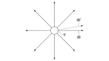
- Figure 4 is a diagram for explaining a method for discretizing the moving direction of the user U.
- the information acquisition unit 110 may, for example, set multiple candidate moving directions (eight in Figure 4) based on the moving body M, and acquire as the moving direction UD the candidate moving direction that forms the smallest angle with the detected moving direction UD' of the user U. This can reduce the processing load on the control device 100.
- the area setting unit 120 converts an image including the user U captured by the camera 10 into a bird's-eye view coordinate system, and sets a predetermined area R in the bird's-eye view coordinate system with the moving object M as a reference (for example, the center).
- FIG. 5 is a diagram showing an example of the predetermined area R set by the area setting unit 120.
- FIG. 5 shows an image obtained by converting an image including the user U captured by the camera 10 into the bird's-eye view coordinate system.
- the symbol UL represents a straight line along the moving direction of the user U acquired by the information acquisition unit 110.
- the area setting unit 120 sets a circle of radius r centered on the moving object M as the predetermined area R.
- the radius r is an example of a "parameter that defines a predetermined area" in the claims.
- the predetermined area R is not limited to a circle, and may be an area having any shape and area that includes at least the moving object M, such as an ellipse.
- the target position determination unit 130 determines the target position to which the moving body M will head, based on a straight line UL along the direction of movement of the user U and a specified region R set by the region setting unit 120. More specifically, of the intersection points P1 and P2 between the straight line UL and the specified region R, the target position determination unit 130 determines the intersection point P2, which is the farthest from the user U in the direction of movement of the user U, as the target position. When the straight line UL and the specified region R are in contact with each other, the target position determination unit 130 determines the point of contact as the target position.
- the driving control unit 140 controls the driving device 200 so that the moving body M moves to the target position determined by the target position determination unit 130.
- the driving device 200 includes, for example, a motor that drives the driving wheels, a battery that stores power to be supplied to the motor, a steering device that adjusts the steering angle of the steering wheels, and an ECU (Electronic Control Unit) that controls these components.
- the ECU controls the above components according to information input from the driving control unit 140.
- the driving device 200 may include an internal combustion engine, a fuel cell, or the like as a driving force output means or a power generation means.
- the driving device 200 may also include a braking device that utilizes frictional force or air resistance.
- the control device 100 acquires information regarding the moving direction of the user U based on an image including the user U captured by the camera 10, and controls the moving body M to lead the user U, taking into account the moving direction of the user U.
- the moving body M can be appropriately controlled to lead the user.
- a situation has been described in which the straight line UL along the moving direction of the user U and the predetermined region R set by the region setting unit 120 have one or more intersections (at least are in contact).
- the straight line UL and the predetermined region R do not necessarily have an intersection.
- the intersections do not necessarily exist in front of the moving direction of the user U.
- FIG. 6 is a diagram showing an example of another situation in which the specified region R is set by the region setting unit 120.
- FIG. 6 shows a situation in which the specified region R set by the region setting unit 120 does not have an intersection with the straight line UL.
- the region setting unit 120 draws a perpendicular line from the moving body M to the straight line UL and determines the intersection of the perpendicular line and the straight line UL (i.e., the foot of the perpendicular line) as the target position P.
- the region setting unit 120 increases the value of the radius r until the specified region R touches the straight line UL and determines the obtained tangent point as the target position P.
- FIG. 7 is a diagram showing an example of another situation in which the specified region R is set by the region setting unit 120.
- FIG. 7 shows a situation in which the specified region R set by the region setting unit 120 has two intersections P1' and P2' with the straight line UL, but neither intersection is located in the traveling direction of the moving body M.
- the target position determination unit 130 first determines the intersection P2', which is closer to the moving body M, as the target position, and the traveling control unit 140 causes the moving body M to travel to the determined target position P2'.
- the area setting unit 120 again sets the predetermined area R based on the moving body M as the operation of the next cycle, and the target position determination unit 130 obtains the intersection points P1 and P2 with the straight line UL.
- the target position determination unit 130 determines the intersection point P2 as the target position of the moving body M, and the traveling control unit 140 causes the moving body M to travel to the determined target position P2.
- the control device 100 repeats the control cycle, and the moving body M can return to leading the user U.
- the travel control unit 140 may control the travel of the moving body M so that the travel speed of the moving body M is always faster than the travel speed of the user U while the moving body M is located behind the user U.
- the control device 100 repeats the above control cycle, so that the moving body M can reliably return to leading the user U.
- the region setting unit 120 may increase the value of the radius r until the intersection point is located in the travel direction of the user U, and determine the intersection point obtained in the travel direction of the user U as the target position P.
- FIG. 8 is a diagram showing an example of another situation in which the specified region R is set by the region setting unit 120. While leading the user U, the control device 100 measures the average distance between the user U and the moving body M, and if the distance d between the user U and the moving body M significantly deviates from the average distance, the control device 100 may adjust the distance traveled by the moving body M per unit time (i.e., the moving speed) by changing the value of the radius r.
- the distance d is an example of "proximity" in the claims.
- the area setting unit 120 increases the value of the radius r, and the target position determination unit 130 shifts the target position P2' to the target position P2.
- the moving body M is controlled to travel a longer distance in the same control cycle, and as a result, the moving speed of the moving body M increases.
- the moving body M moves away from the user U, and a distance that is comfortable for the user U can be maintained.
- the area setting unit 120 decreases the value of the radius r, and the target position determination unit 130 shifts the target position P2 to the target position P2'.
- the moving body M is controlled to travel a shorter distance in the same control cycle, and as a result, the moving speed of the moving body M decreases.
- the moving body M approaches the user U, and a comfortable distance for the user U can be maintained.
- the region setting unit 120 may change the value of the radius r depending on the appearance or moving speed of the user U.
- the region setting unit 120 may calculate an index value related to the walking ability of the user U, such as the age or degree of fatigue, based on an image including the user U captured by the camera 10, and may set the value of the radius r to be smaller as the calculated index value is lower, thereby decreasing the moving speed of the moving body M.
- the region setting unit 120 may set the value of the radius r to be higher (lower) as the measured moving speed of the user U is higher (lower), thereby increasing (decreasing) the moving speed of the moving body M. This makes it possible to prevent the user U from feeling uncomfortable due to the moving speed of the moving body M deviating from his/her own moving speed.
- the area setting unit 120 may change the value of the radius r depending on the degree of congestion in the driving environment in which the moving body M is driving. For example, when the image captured by the camera 10 includes a predetermined number or more of people or obstacles other than the user U, the area setting unit 120 may set the value of the radius r to a small value and reduce the moving speed of the moving body M. This can reduce the risk of other pedestrians cutting in between the user U and the moving body M, or of the moving body M coming into contact with other pedestrians.
- the area setting unit 120 may set the value of the radius r to a large value and increase the moving speed of the moving body M. This allows the user U to move comfortably through an area with a large free space.
- Fig. 9 is a flowchart showing an example of the flow of processing executed by the control device 100.
- the processing of the flowchart shown in Fig. 9 is executed, for example, when a user U sets a leading mode on the HMI 30.
- the information acquisition unit 110 acquires information regarding the moving direction of the user U (step S100).
- the region setting unit 120 sets a predetermined region R based on the moving body M (step S102).
- the target position determination unit 130 determines whether a straight line UL along the moving direction of the user U intersects with the predetermined region R (step S104).
- the target position determination unit 130 determines the intersection point that is farthest from the user U in the direction of movement of the user U as the target position (step S106). On the other hand, if it is determined that the straight line UL and the specified region R do not intersect, the target position determination unit 130 determines the foot of a perpendicular line from the moving body M to the straight line UL as the target position (step S108). Next, the traveling control unit 140 causes the moving body M to travel to the determined target position (step S110). This ends the processing of this flowchart.
- the moving body M is set to be switchable between a guidance mode and a leading mode, and the control device 100 constantly leads the moving body M while the guidance mode is set for the moving body M.
- the present invention is not limited to such a configuration, and the present invention can be applied to cases in which the moving body M leads the user at least temporarily. For example, when the moving body M runs alongside the user or pursues the user and detects a predetermined situation (e.g., the presence of an obstacle or traffic congestion) in the user's traveling direction, the moving body M may temporarily lead the user by executing the algorithm of the present invention.
- a predetermined situation e.g., the presence of an obstacle or traffic congestion
- the control device obtains information regarding the user's moving direction, sets a predetermined area based on the moving body, determines a target position to which the moving body will head based on the moving direction and the predetermined area, and causes the moving body to travel to the target position. This makes it possible to appropriately control the moving body to lead the user.
- a control device of a moving object leading a user a storage medium for storing computer-readable instructions; a processor coupled to the storage medium; The processor executes the computer-readable instructions to: acquiring information regarding a moving direction of the user, setting a predetermined area based on the moving body, determining a target position to which the moving body is to move based on the moving direction and the predetermined area, and controlling a drive device attached to the moving body so that the moving body moves to the target position;
- the mobile object control device is configured as follows.
Landscapes
- Engineering & Computer Science (AREA)
- Aviation & Aerospace Engineering (AREA)
- Radar, Positioning & Navigation (AREA)
- Remote Sensing (AREA)
- Physics & Mathematics (AREA)
- General Physics & Mathematics (AREA)
- Automation & Control Theory (AREA)
- Control Of Position, Course, Altitude, Or Attitude Of Moving Bodies (AREA)
Abstract
Description
(1):この発明の一態様に係る移動体制御装置は、ユーザを少なくとも一時的に先導する移動体の制御装置であって、前記ユーザの移動方向に関する情報を取得する情報取得部と、前記移動体を基準とした所定領域を設定する領域設定部と、前記移動方向と前記所定領域とに基づいて、前記移動体が向かう目標位置を決定する目標位置決定部と、を備えるものである。
図1は、実施形態に係る制御装置を備える移動体Mの一例を示す図である。移動体Mは、自律移動型のロボットである。移動体Mは、ユーザUの行動を支援する。移動体Mは、例えば、ユーザUの指定した位置に停車して、目的地の入力を受け付けた後に当該目的地までユーザUを誘導したり、又は目的地の入力を受け付けることなく、ユーザUの移動方向に関する情報に基づいて、ユーザUを先導(すなわち、ユーザUの移動方向に関して前方を走行)したりする。このように、本実施形態において、移動体Mは、歩行者としてのユーザUを誘導したり、先導したりするものとして説明するが、移動体Mは、ユーザUが搭乗可能なものであってもよく、その場合、ユーザUによる目的地の入力を受け付けた後に、当該ユーザUを乗せて目的地まで移動するものであってもよい。
図5では、ユーザUの移動方向に沿った直線ULと、領域設定部120によって設定された所定領域Rとが一以上の交点を有している(少なくとも、接している)状況について説明した。しかしながら、例えば、ユーザUと移動体Mとの距離が離れている場合、直線ULと所定領域Rとは必ずしも交点を有するとは限らない。また、例えば、直線ULと所定領域Rとが一以上の交点を有している場合であっても、当該交点が必ずしもユーザUの進行方向前方に存在するとも限らない。以下、図5に示した状況とは異なる状況における領域設定部120の動作について説明する。
次に、図9を参照して、制御装置100によって実行される処理の流れについて説明する。図9は、制御装置100によって実行される処理の流れの一例を示すフローチャートである。図9に示すフローチャートの処理は、例えば、ユーザUが、HMI30上で先導モードを設定した際に実行されるものである。
ユーザを先導する移動体の制御装置が、
コンピュータによって読み込み可能な命令(computer-readable instructions)を格納する記憶媒体(storage medium)と、
前記記憶媒体に接続されたプロセッサと、を備え、
前記プロセッサは、前記コンピュータによって読み込み可能な命令を実行することにより(the processor executing the computer-readable instructions to:)、
前記ユーザの移動方向に関する情報を取得し、前記移動体を基準とした所定領域を設定し、前記移動方向と前記所定領域とに基づいて、前記移動体が向かう目標位置を決定し、前記目標位置まで前記移動体が移動するように前記移動体に取り付けられた駆動装置を制御する、
ように構成されている、移動体制御装置。
100 制御装置
110 情報取得部
120 領域設定部
130 目標位置決定部
140 走行制御部
Claims (12)
- ユーザを少なくとも一時的に先導する移動体の制御装置であって、
前記ユーザの移動方向に関する情報を取得する情報取得部と、
前記移動体を基準とした所定領域を設定する領域設定部と、
前記移動方向と前記所定領域とに基づいて、前記移動体が向かう目標位置を決定する目標位置決定部と、
前記目標位置まで前記移動体が移動するように前記移動体に取り付けられた駆動装置を制御する走行制御部と、を備える、
制御装置。 - 前記所定領域は、円または楕円である、
請求項1に記載の制御装置。 - 前記目標位置決定部は、前記ユーザを通過し前記移動方向に沿った直線と前記所定領域との交点を前記目標位置として決定する、
請求項1に記載の制御装置。 - 前記目標位置決定部は、前記直線と前記所定領域との交点が複数個ある場合、前記移動方向上にある前記ユーザと最も離れた交点を前記目標位置として決定する、
請求項3に記載の制御装置。 - 前記目標位置決定部は、前記直線と前記所定領域との交点が存在しない場合、前記移動体から前記直線への垂線の足を前記目標位置として決定する、
請求項3に記載の制御装置。 - 前記走行制御部が前記移動体を前記目標位置まで移動させた場合、前記情報取得部は、前記ユーザの移動方向に関する情報を再取得し、前記領域設定部は、前記目標位置に移動した前記移動体を基準とした所定領域を再設定し、前記目標位置決定部は、再取得された前記移動方向と再設定された前記所定領域とに基づいて、前記移動体が向かう目標位置を再決定する、
請求項1に記載の制御装置。 - 前記領域設定部は、前記ユーザの外見又は移動速度に応じて、前記所定領域を規定するパラメータを変更する、
請求項1に記載の制御装置。 - 前記領域設定部は、前記ユーザによる入力に応じて、前記所定領域を規定するパラメータを変更する、
請求項1に記載の制御装置。 - 前記領域設定部は、前記ユーザによる前記移動体への接近度に応じて、前記所定領域を規定するパラメータを変更する、
請求項1に記載の制御装置。 - 前記領域設定部は、前記移動体が走行する走行環境の混雑度に応じて、前記所定領域を規定するパラメータを変更する、
請求項1に記載の制御装置。 - ユーザを少なくとも一時的に先導する移動体の制御装置が、
前記ユーザの移動方向に関する情報を取得し、
前記移動体を基準とした所定領域を設定し、
前記移動方向と前記所定領域とに基づいて、前記移動体が向かう目標位置を決定し、
前記目標位置まで前記移動体が移動するように前記移動体に取り付けられた駆動装置を制御する、
制御方法。 - ユーザを少なくとも一時的に先導する移動体の制御装置に、
前記ユーザの移動方向に関する情報を取得させ、
前記移動体を基準とした所定領域を設定させ、
前記移動方向と前記所定領域とに基づいて、前記移動体が向かう目標位置を決定させ、
前記目標位置まで前記移動体が移動するように前記移動体に取り付けられた駆動装置を制御させる、
プログラム。
Priority Applications (4)
| Application Number | Priority Date | Filing Date | Title |
|---|---|---|---|
| JP2025507920A JPWO2024194940A1 (ja) | 2023-03-17 | 2023-03-17 | |
| CN202380095385.1A CN120731411A (zh) | 2023-03-17 | 2023-03-17 | 控制装置、控制方法以及程序 |
| EP23928525.7A EP4664222A4 (en) | 2023-03-17 | 2023-03-17 | CONTROL DEVICE, CONTROL METHOD AND PROGRAM |
| PCT/JP2023/010663 WO2024194940A1 (ja) | 2023-03-17 | 2023-03-17 | 制御装置、制御方法、およびプログラム |
Applications Claiming Priority (1)
| Application Number | Priority Date | Filing Date | Title |
|---|---|---|---|
| PCT/JP2023/010663 WO2024194940A1 (ja) | 2023-03-17 | 2023-03-17 | 制御装置、制御方法、およびプログラム |
Publications (1)
| Publication Number | Publication Date |
|---|---|
| WO2024194940A1 true WO2024194940A1 (ja) | 2024-09-26 |
Family
ID=92841094
Family Applications (1)
| Application Number | Title | Priority Date | Filing Date |
|---|---|---|---|
| PCT/JP2023/010663 Ceased WO2024194940A1 (ja) | 2023-03-17 | 2023-03-17 | 制御装置、制御方法、およびプログラム |
Country Status (4)
| Country | Link |
|---|---|
| EP (1) | EP4664222A4 (ja) |
| JP (1) | JPWO2024194940A1 (ja) |
| CN (1) | CN120731411A (ja) |
| WO (1) | WO2024194940A1 (ja) |
Cited By (1)
| Publication number | Priority date | Publication date | Assignee | Title |
|---|---|---|---|---|
| WO2026069624A1 (ja) * | 2024-09-27 | 2026-04-02 | 本田技研工業株式会社 | 移動体、その制御装置及び制御方法、プログラム並びにシステム |
Citations (3)
| Publication number | Priority date | Publication date | Assignee | Title |
|---|---|---|---|---|
| JP2011224679A (ja) * | 2010-04-16 | 2011-11-10 | Toyota Motor Corp | 応対ロボット、応対制御方法、及び応対制御プログラム |
| JP2016184337A (ja) * | 2015-03-26 | 2016-10-20 | 株式会社エクォス・リサーチ | 移動体 |
| JP2019175333A (ja) * | 2018-03-29 | 2019-10-10 | 株式会社エクォス・リサーチ | 移動体 |
Family Cites Families (4)
| Publication number | Priority date | Publication date | Assignee | Title |
|---|---|---|---|---|
| JP5569073B2 (ja) * | 2010-03-18 | 2014-08-13 | 富士通株式会社 | サービス提供装置、サービス提供プログラム及びサービスロボット |
| JP6894595B2 (ja) * | 2018-03-28 | 2021-06-30 | 株式会社エクォス・リサーチ | 移動体 |
| JP2019179285A (ja) * | 2018-03-30 | 2019-10-17 | 株式会社エクォス・リサーチ | 移動体 |
| JP7281720B2 (ja) | 2019-06-06 | 2023-05-26 | パナソニックIpマネジメント株式会社 | 自律移動装置およびその制御方法 |
-
2023
- 2023-03-17 CN CN202380095385.1A patent/CN120731411A/zh active Pending
- 2023-03-17 JP JP2025507920A patent/JPWO2024194940A1/ja active Pending
- 2023-03-17 EP EP23928525.7A patent/EP4664222A4/en active Pending
- 2023-03-17 WO PCT/JP2023/010663 patent/WO2024194940A1/ja not_active Ceased
Patent Citations (3)
| Publication number | Priority date | Publication date | Assignee | Title |
|---|---|---|---|---|
| JP2011224679A (ja) * | 2010-04-16 | 2011-11-10 | Toyota Motor Corp | 応対ロボット、応対制御方法、及び応対制御プログラム |
| JP2016184337A (ja) * | 2015-03-26 | 2016-10-20 | 株式会社エクォス・リサーチ | 移動体 |
| JP2019175333A (ja) * | 2018-03-29 | 2019-10-10 | 株式会社エクォス・リサーチ | 移動体 |
Non-Patent Citations (1)
| Title |
|---|
| See also references of EP4664222A1 * |
Cited By (1)
| Publication number | Priority date | Publication date | Assignee | Title |
|---|---|---|---|---|
| WO2026069624A1 (ja) * | 2024-09-27 | 2026-04-02 | 本田技研工業株式会社 | 移動体、その制御装置及び制御方法、プログラム並びにシステム |
Also Published As
| Publication number | Publication date |
|---|---|
| JPWO2024194940A1 (ja) | 2024-09-26 |
| CN120731411A (zh) | 2025-09-30 |
| EP4664222A1 (en) | 2025-12-17 |
| EP4664222A4 (en) | 2026-01-21 |
Similar Documents
| Publication | Publication Date | Title |
|---|---|---|
| JP5768273B2 (ja) | 歩行者の軌跡を予測して自己の回避行動を決定するロボット | |
| JP2018190217A (ja) | 運転者監視装置、及び運転者監視方法 | |
| US11099564B2 (en) | Vehicle control device, vehicle control method, and storage medium | |
| CN107111317B (zh) | 移动体 | |
| JP2006134221A (ja) | 追従移動装置 | |
| US12291242B2 (en) | Mobile body control device, mobile body control method, mobile body, information processing method, and storage medium | |
| US20250021106A1 (en) | Moving object control apparatus, method for controlling moving object, moving object, information processing method, and storage medium | |
| US20180329424A1 (en) | Portable mobile robot and operation thereof | |
| US12135546B2 (en) | Mobile object control system, mobile object, mobile object control method, and storage medium | |
| JP2022039469A (ja) | 車両走行制御装置 | |
| EP4664222A1 (en) | Control device, control method, and program | |
| US12189391B2 (en) | Control system, mobile object, control method, and storage medium | |
| US20250187595A1 (en) | Moving object control system, control method, non-transitory storage medium, and moving object | |
| EP4664223A1 (en) | Control device, control method, and program | |
| US20260093271A1 (en) | System and method for controlling mobile body, and medium | |
| US20260091497A1 (en) | System and method for predicting movement of person, and medium | |
| JP7724178B2 (ja) | 位置特定システムとそれを搭載した車両 | |
| WO2025203361A1 (ja) | 制御装置、移動体システム、制御方法、およびプログラム | |
| WO2025203272A1 (ja) | 制御装置、制御方法、およびプログラム | |
| WO2025203310A1 (ja) | 制御装置、制御方法、およびプログラム | |
| WO2026069624A1 (ja) | 移動体、その制御装置及び制御方法、プログラム並びにシステム | |
| WO2025191789A1 (ja) | 制御装置、制御方法、およびプログラム | |
| WO2025191786A1 (ja) | 制御装置、制御方法、およびプログラム | |
| WO2024128225A1 (ja) | 移動体制御装置、移動体制御方法、および記憶媒体 | |
| WO2026069656A1 (ja) | 移動体の制御装置、移動体制御システム、移動体の制御方法、およびプログラム |
Legal Events
| Date | Code | Title | Description |
|---|---|---|---|
| ENP | Entry into the national phase |
Ref document number: 2025507920 Country of ref document: JP Kind code of ref document: A |
|
| WWE | Wipo information: entry into national phase |
Ref document number: 2025507920 Country of ref document: JP |
|
| WWE | Wipo information: entry into national phase |
Ref document number: 202380095385.1 Country of ref document: CN |
|
| WWP | Wipo information: published in national office |
Ref document number: 202380095385.1 Country of ref document: CN |
|
| NENP | Non-entry into the national phase |
Ref country code: DE |
|
| 121 | Ep: the epo has been informed by wipo that ep was designated in this application |
Ref document number: 23928525 Country of ref document: EP Kind code of ref document: A1 |
|
| WWP | Wipo information: published in national office |
Ref document number: 2023928525 Country of ref document: EP |