WO2024201568A1 - Système de montage de composant électronique et procédé d'inspection de montage de composant électronique - Google Patents
Système de montage de composant électronique et procédé d'inspection de montage de composant électronique Download PDFInfo
- Publication number
- WO2024201568A1 WO2024201568A1 PCT/JP2023/011822 JP2023011822W WO2024201568A1 WO 2024201568 A1 WO2024201568 A1 WO 2024201568A1 JP 2023011822 W JP2023011822 W JP 2023011822W WO 2024201568 A1 WO2024201568 A1 WO 2024201568A1
- Authority
- WO
- WIPO (PCT)
- Prior art keywords
- component
- component mounting
- mounting state
- electronic component
- determination unit
- Prior art date
- Legal status (The legal status is an assumption and is not a legal conclusion. Google has not performed a legal analysis and makes no representation as to the accuracy of the status listed.)
- Ceased
Links
Images


Classifications
-
- H—ELECTRICITY
- H05—ELECTRIC TECHNIQUES NOT OTHERWISE PROVIDED FOR
- H05K—PRINTED CIRCUITS; CASINGS OR CONSTRUCTIONAL DETAILS OF ELECTRIC APPARATUS; MANUFACTURE OF ASSEMBLAGES OF ELECTRICAL COMPONENTS
- H05K13/00—Apparatus or processes specially adapted for manufacturing or adjusting assemblages of electric components
- H05K13/08—Monitoring manufacture of assemblages
- H05K13/083—Quality monitoring using results from monitoring devices, e.g. feedback loops
-
- H—ELECTRICITY
- H05—ELECTRIC TECHNIQUES NOT OTHERWISE PROVIDED FOR
- H05K—PRINTED CIRCUITS; CASINGS OR CONSTRUCTIONAL DETAILS OF ELECTRIC APPARATUS; MANUFACTURE OF ASSEMBLAGES OF ELECTRICAL COMPONENTS
- H05K13/00—Apparatus or processes specially adapted for manufacturing or adjusting assemblages of electric components
- H05K13/08—Monitoring manufacture of assemblages
- H05K13/081—Integration of optical monitoring devices in assembly lines; Processes using optical monitoring devices specially adapted for controlling devices or machines in assembly lines
- H05K13/0815—Controlling of component placement on the substrate during or after manufacturing
Definitions
- the technology disclosed in this specification relates to an electronic component mounting system and an electronic component mounting inspection method.
- a line that mounts electronic components on a board is generally composed of a solder printer, a print inspection machine, an electronic component mounting machine, a reflow oven, a board appearance inspection machine, etc.
- the electronic component mounting machine electronic components are mounted at the mounting position on the board.
- the electronic components are photographed by a camera of the electronic component mounting machine, and an appearance inspection is performed to determine whether or not the electronic components are present at the mounting position by image recognition based on the photographed image.
- machine learning has been used for such appearance inspections.
- Patent Document 1 Publication WO2019/155593
- a learned model for each component created by machine learning is used to determine whether the electronic components adsorbed by the suction nozzle are normally or abnormally adsorbed, and electronic components determined to be normally adsorbed are mounted on the board. After the components are mounted, it is inspected whether or not a mounting failure has occurred, and the mounting failure occurrence rate is calculated for each component. Then, a threshold value for determining the mounting failure occurrence rate is set in advance, and it is determined whether or not there are electronic components whose mounting failure occurrence rate exceeds this judgment threshold value. If there is an electronic component that exceeds the above judgment threshold, it is determined that the image recognition accuracy for that electronic component is low, and additional learning is started to adjust the part-specific trained model. At this time, additional learning is performed based on images obtained by actually capturing images of the electronic component.
- This specification provides technology for stably inspecting the presence or absence of components during component mounting while maintaining board production efficiency.
- the electronic component mounting system includes an imaging unit, a first component mounting state determination unit, a second component mounting state determination unit, a component change detection unit, and an automatic determination unit switching unit.
- the imaging unit captures an image of a component inspection area of the board including electronic components mounted on the board.
- the first component mounting state determination unit uses a component mounting state determiner created by machine learning to determine the mounting state of the electronic components based on the image captured by the imaging unit.
- the second component mounting state determination unit is provided separately from the first component mounting state determination unit and determines the mounting state of the electronic components based on the image.
- the component change detection unit detects whether a change has occurred in the electronic components to be mounted.
- the automatic determination unit switching unit automatically switches from the first component mounting state determination unit to the second component mounting state determination unit, and causes the second component mounting state determination unit to determine the mounting state of the electronic components. Therefore, according to the above-mentioned configuration, if there is no change in the electronic component to be mounted, the mounting state of the electronic component is determined using a component mounting state determiner created by machine learning. Also, even if a change occurs in the electronic component to be mounted, the mounting state of the electronic component is determined without using the component mounting state determiner. This eliminates the need to stop board production, and allows stable component presence inspection during component mounting while maintaining board production efficiency.
- This specification also provides an electronic component mounting inspection method for inspecting the mounting state of electronic components based on an image obtained by capturing an image of a component inspection area including electronic components mounted on a board.
- the electronic component mounting inspection method includes a first component mounting state determination step, a component change detection step, and a determination unit automatic switching step.
- a component mounting state determiner created by machine learning is used to determine the mounting state of the electronic components based on the image.
- the component change detection step it is detected whether or not a change has occurred in the electronic components provided for mounting.
- the determination unit automatic switching step when a change in the electronic components is detected in the component change detection step, the first component mounting state determination unit is automatically switched to a second component mounting state determination unit provided separately from the first component mounting state determination unit. Furthermore, in the determination unit automatic switching step, the second component mounting state determination unit determines the mounting state of the electronic components based on the image.
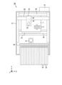
- FIG. 1 is a schematic plan view showing an electronic component mounting system according to an embodiment of the present invention
- FIG. 2 is a schematic cross-sectional view showing an electronic component mounting machine.
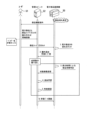
- FIG. 1 is a schematic diagram for explaining an electronic component mounting inspection method.
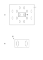
- 1A is a schematic plan view showing a substrate before components are mounted thereon
- FIG. 1B is a schematic plan view showing a first image
- 1A is a schematic plan view showing the board after components are mounted
- FIG. 1B is a schematic plan view showing a second image.
- the second component mounting state determination unit may be a component presence/absence determination unit that determines whether or not an electronic component is present at the mounting position by performing differential processing to compare the difference between an image of the component inspection area taken before component mounting and an image of the component inspection area taken after component mounting.
- the electronic component mounting system described in Aspect 1 above may further include an additional learning unit that collects, as learning data, images taken after component mounting that are obtained during the difference processing performed by the second component mounting state determination unit, and uses the learning data for additional learning to generate a new component mounting state determiner.
- the electronic component mounting system described in Aspect 2 above may further include an electronic component mounting machine that mounts electronic components on a board, and a management computer that manages the electronic component mounting machine, and the additional learning unit may be provided in the management computer.
- the first component mounting state determination unit may be provided in the electronic component mounting machine.
- the management computer may perform a performance evaluation on a new component mounting state determiner, and when the evaluation result indicates that the new component mounting state determiner has performance at or above a predetermined level, may determine that the new component mounting state determiner is complete.
- the component change detection unit detects whether or not a change has occurred in at least one of component information of the electronic component, the component name, the vendor name, and the lot, and the automatic judgment unit switching unit performs automatic switching from the first component mounting state judgment unit to the second component mounting state judgment unit when the judgment result of the component change detection unit is yes, and does not need to perform automatic switching when the judgment result of the component change detection unit is no.
- the component change detection unit detects whether or not a change has occurred in at least one of component information of the electronic component, the component name, the vendor name, and the lot, and the automatic judgment unit switching unit automatically switches from the first component mounting state judgment unit to the second component mounting state judgment unit when the judgment result of the component change detection unit is positive, and automatically switches if a change has occurred in the supply status of the electronic components when the judgment result of the component change detection unit is negative, but does not have to perform automatic switching if there has been no change in the supply status of the electronic components.
- the case where a change occurs in the supply state of the electronic components may be a case where a splicing operation is performed on a tape that supplies the electronic components.
- FIG. 1 is a schematic plan view showing the electronic component mounting system 11 according to the present embodiment.
- the electronic component mounting system 11 is a system for mounting an electronic component 2 (see FIG. 2) on a board 1.
- the electronic component mounting system 11 is configured by arranging a plurality of electronic component mounting machines 20 along the conveying direction (X direction) of the board 1.
- the electronic component 2 is, for example, a component having a component body 3 and a plurality of terminals 4 provided on the component body 3.
- Specific examples of the electronic component 2 include semiconductor packages such as QFP (Quad Flat Package) and BGA (Ball Grid Array), and chip components such as chip resistors and chip capacitors.
- a solder printer and a print inspection machine are arranged upstream of the multiple electronic component mounting machines 20.
- the solder printer prints a solder pattern on the board 1 and conveys the board 1 after the solder pattern has been printed to the print inspection machine.
- the print inspection machine inspects the solder pattern printed on the board 1 and conveys the board 1 after the solder pattern has been inspected to the electronic component mounting machine 20.
- a reflow furnace and a board appearance inspection machine are arranged downstream of the multiple electronic component mounting machines 20. The reflow furnace reflows the board 1 conveyed from the electronic component mounting machine 20.
- the reflow furnace heats the board 1 conveyed therein to melt the solder, and solders the electronic components 2 to the board 1.
- the board appearance inspection machine inspects the board 1 after component mounting that is conveyed out of the reflow furnace.
- the board appearance inspection machine inspects whether the electronic components 2 are properly mounted on the board 1. If the electronic component 2 is properly mounted on the board 1, the board visual inspection machine removes the board 1 from the electronic component mounting system 11.
- the electronic component mounting machine 20 is a device for mounting electronic components 2 on a board 1.
- the electronic component mounting machine 20 includes a plurality of component feeders 22, an XY robot 23, a board transport lane 24, a head unit 31, a parts camera 41, a control device 51, etc.
- Each component feeder 22 stores multiple electronic components 2.
- the component feeders 22 are removably attached to the feeder holding portion 25 and supply the electronic components 2 to the head unit 31.
- the component feeders 22 in this embodiment are tape-type feeders that store multiple electronic components 2 on a tape.
- the XY robot 23 moves the head unit 31 between above the component feeder 22 and above the board 1 by moving the head unit 31 in the X and Y directions.
- the XY robot 23 is composed of a guide rail that guides the head unit 31, a movement mechanism that moves the head unit 31 along the guide rail, a motor that drives the movement mechanism, etc.
- the XY robot 23 is housed inside the housing 21 and is positioned above the board 1. The head unit 31 moves through the space from above the component feeder 22 to above the board 1 by the XY robot 23.
- the board transport lane 24 is a device that performs the tasks of transporting the board 1 into the electronic component mounting machine 20, positioning the board 1 before components are mounted at the work position P1, and transporting the board 1 after components are mounted from the work position P1.
- the board transport lane 24 can be composed of, for example, a pair of belt conveyors, a support device (not shown) that is attached to the belt conveyors and supports the board 1 from below, and a drive device (not shown) that drives the belt conveyors.
- the board 1 is transported from the upstream (left side in FIG. 1) to the downstream (right side in FIG. 1) of the electronic component mounting system 11.
- the head unit 31 is a movable unit that mounts the electronic components 2 on the board 1.
- the head unit 31 includes a component mounting head 32 and a mark camera 34 (an example of an imaging unit).
- the component mounting head 32 is attached to the underside of the head unit 31, and includes a number of suction nozzles 33.
- Each suction nozzle 33 is detachably supported by the component mounting head 32.
- Each suction nozzle 33 is raised and lowered in the vertical direction (Z direction) by an actuator (not shown) housed in the component mounting head 32, and is configured to be able to suck up the electronic components 2.
- the suction nozzle 33 is moved downward until its suction surface comes into contact with the electronic component 2 contained in the component feeder 22.
- the suction nozzle 33 picks up the electronic component 2, and the suction nozzle 33 is moved upward.
- the XY robot 23 is driven to position the head unit 31 relative to the board 1.
- the suction nozzle 33 is then lowered toward the board 1, thereby mounting the electronic component 2 on the board 1.
- the head unit 31 and suction nozzle 33 are automatically replaced by a replacement robot (not shown).
- the mark camera 34 is mounted near the component mounting head 32 in the head unit 31, and is configured to be movable together with the component mounting head 32.
- the mark camera 34 moves above the board 1 that has been brought into the work position P1 by the board transport lane 24, and captures an image of a mark (not shown) affixed to the board 1, as well as an image of the component inspection area A1 (see Figures 4(a) and 5(a)) of the board 1.
- the mark camera 34 is configured using an imaging element such as a CCD (Charge Coupled Device) or a CMOS (Complementary Metal Oxide Semiconductor).
- the part camera 41 is located between the component feeder 22 and the board transport lane 24, below the movement path of the head unit 31.
- the part camera 41 captures an image of the electronic component 2 picked up by the head unit 31 from below.
- the part camera 41 is also configured using an imaging element such as a CCD or CMOS.
- the control device 51 is a computer that includes a CPU, memory, and the like.
- the control device 51 is connected to the component feeder 22, XY robot 23, board transport lane 24, head unit 31, parts camera 41, and exchange robot via a bus so that they can communicate with each other.
- a management computer 52 (see FIG. 1) that manages each electronic component mounting machine 20 is connected to the control device 51 via a bus so that they can communicate with each other.
- Each control device 51 controls the operation of each part (component feeder 22, XY robot 23, board transport lane 24, head unit 31, parts camera 41, and exchange robot) based on a production program stored in the management computer 52. Through this control, each control device 51 executes a mounting process for mounting multiple electronic components 2 on a board 1, and the like.
- the memory in the control device 51 also stores learned data (an example of a component mounting state determiner).
- the memory also stores a component presence/absence determination program.
- the learned data is created as follows. First, two types of images are prepared: "images before the electronic component 2 is mounted (component-free images)" and “images of the electronic component 2 in a state where it is properly mounted (component-present images)”. Next, the learned data is created by learning features extracted from these images.
- the control device 51 drives the board transport lane 24 to transport the board 1 to the work position P1 in the electronic component mounting machine 20.
- the control device 51 then drives the XY robot 23 to move the head unit 31 to the component suction position, and causes the suction nozzle 33 of the head unit 31 to suction the electronic component 2 at the component suction position.
- the control device 51 then moves the head unit 31 to the board 1 while passing above the parts camera 41, and drives the parts camera 41 to capture an image of the electronic component 2 during the movement, thereby checking the condition of the electronic component 2.
- the control device 51 inspects the mounting state of the electronic component 2 based on the image obtained by capturing an image of the component inspection area A1 (see FIG. 4(a) and FIG. 5(a)) set on the board 1. Specifically, the control device 51 first drives the mark camera 34 to capture an image of a mark (not shown) attached to the board 1, and executes image recognition processing based on the captured image data to recognize the position where the electronic component 2 should be mounted. Next, the control device 51 drives the mark camera 34 to capture an image of the component inspection area A1 (including the component mounting position) before the component is mounted, thereby obtaining a first image 61 (see FIG. 4(b)).
- control device 51 determines the mounting state of the electronic component 2 (whether the electronic component 2 is present or not) using a component presence/absence determiner (learned data) created by machine learning, the step of obtaining the first image 61 may be omitted. Next, the control device 51 lowers the suction nozzle 33 and releases the electronic component 2 that was being sucked. This operation causes the electronic component 2 to be mounted on the board 1.
- the control device 51 drives the mark camera 34 again to capture an image of the component inspection area A1 after the component is mounted, thereby obtaining a second image 62 (see FIG. 5B).
- the control device 51 uses a component presence/absence determiner (trained data) created by machine learning to determine the mounting state of the electronic component 2 (whether or not the electronic component 2 is present) based on the image (first component mounting state determination step).
- the feature amount of the second image 62 which is the subject of mounting state determination, is input to the trained data to determine whether or not the electronic component 2 is present at the mounting position. Note that the determination by the first component mounting state determination unit continues as long as there is no change in the electronic component 2.
- the control device 51 displays a guide (component supply guide) requesting the supply of electronic components 2 on the display unit (not shown) of the electronic component mounting machine 20.
- the user U1 removes the component feeder 22 in which the component run out has occurred from the feeder holding unit 25 of the electronic component mounting machine 20, and prepares a new component feeder 22.
- the user U1 registers the combination information of the electronic components 2 and the component feeder 22 in the prepared component feeder 22 in the management computer 52.
- the user U1 also registers the component information of the electronic components 2 (specifically, the component name, vendor name, and lot of the electronic components 2) in the management computer 52.
- the user U1 then attaches (sets) the prepared component feeder 22 to the feeder holding unit 25.
- the user U1 may supply the electronic components 2 by performing a splicing operation.
- the user U1 registers, in the management computer 52, combination information between the component feeder 22 on which the splicing operation has been performed and the electronic component 2 to be newly joined.
- the combination information between the component feeder 22 and the electronic component 2 may also be registered in the control device 51. In this case, the control device 51 can determine that a change has occurred in the supply status of the electronic component 2 based on the registered information.
- the control device 51 detects whether a change has occurred in the electronic component 2 to be mounted (see “1.” in FIG. 3). Specifically, the control device 51 communicates with the management computer 52 and acquires component information registered in the management computer 52, thereby comparing the component information "before" the component shortage with the component information "after” the component shortage, and detects whether a change has occurred in the component information. The control device 51 also detects whether a change has occurred in at least one of the component information items of the component name, vendor name, and lot of the electronic component 2. Note that in FIG. 3, because the vendor name of the electronic component 2 has changed, the control device 51 determines that the electronic component 2 has been switched.
- the control device 51 detects a change in the electronic component 2 in the component change detection step, i.e., when the judgment result of the component change detection unit is yes, the control device 51 automatically switches the function of the first component mounting state judgment unit of the control device 51 to the function of the second component mounting state judgment unit of the control device 51.
- the second component mounting state judgment unit is provided functionally separately from the first component mounting state judgment unit within the control device 51.
- the control device 51 also automatically switches from the first component mounting state judgment unit to the second component mounting state judgment unit if a change occurs in the supply status of the electronic components 2.
- a change occurs in the supply status of the electronic components 2 when a splicing operation is performed in which another tape containing new electronic components 2 is spliced to the tape of the component feeder 22 that supplies the electronic components 2.
- the control device 51 does not perform automatic switching.
- the control device 51 instructs the management computer 52 to change to the "external additional learning mode" (see “2.” in Figure 3).
- the control device 51 determines the mounting state of the electronic component 2 based on the images 61 and 62.
- the control device 51 of this embodiment performs difference processing to compare the difference between the image of the component inspection area A1 taken before the component is mounted (first image 61) and the image of the component inspection area A1 taken after the component is mounted (second image 62) to determine whether or not the electronic component 2 is present at the mounting position (see “3.” in FIG. 3).
- the image taken after the component is mounted (second image 62) obtained during difference processing is sent to the management computer 52 (target image transmission).
- the control device 51 creates a difference image of the component inspection area A1 using the images 61 and 62.
- the control device 51 smoothes the difference image using a smoothing filter, and then performs binarization processing.
- the control device 51 calculates the area of the difference area of the difference image (the part of the component inspection area A1 that has changed before and after the component is mounted). Then, the control device 51 calculates the difference between the area of the difference area and the area of the electronic component 2, and if the calculated difference is a small value, the control device 51 uses the difference image as a "component present" image and determines that the electronic component 2 is present at the mounting position.
- the area of the difference area of the difference image is, for example, 180,000 ⁇ m 2.
- the difference between the area of the difference area and the area of the electronic component 2 is 0 ⁇ m 2 , and is determined to be a small value.
- the "small value" may be specified by the user U1 or may be a fixed value.
- the control device 51 does not use the difference image as a "component present" image and determines that the electronic component 2 is not present at the mounting position. Specifically, if the electronic component 2 is not shown in the image (second image 62) after the component is mounted (if the electronic component 2 is mis-mounted), the image does not change, so the area of the difference region of the difference image is 0 ⁇ m 2. In this case, the difference between the area of the difference region and the area of the electronic component 2 (for example, 180000 ⁇ m 2 ) is 180000 ⁇ m 2 , which is determined to be not an infinitesimal value.
- the area of the difference region of the difference image is, for example, 60000 ⁇ m 2 .
- the difference between the area of the difference region and the area of the electronic component 2 is 120,000 ⁇ m 2 , which is also determined to be a non-infinite value. Note that the determination as to whether or not the electronic component 2 is present at the mounting position is repeated the required number of times.
- the management computer 52 (an example of an additional learning unit) also collects the second images 62 acquired during the differential processing and transmitted from the control device 51 as learning data, and uses the collected learning data for additional learning to generate new learning data (see "4.” in FIG. 3). Specifically, the management computer 52 extracts features for machine learning from the collected second images 62, performs additional learning, and generates new learned data.
- the management computer 52 performs a performance evaluation on the generated new trained data, and if the evaluation result indicates that the new trained data has performance equal to or higher than a predetermined level, it determines that the new trained data is complete (see "5.” in FIG. 3). Specifically, the management computer 52 uses the new trained data to perform tests on a group of image samples, and measures the success rate of the component presence/absence inspection (determination of whether or not the electronic component 2 is present at the mounting position). Based on the success rate of the component presence/absence inspection, the management computer 52 also determines whether or not the new trained data is complete, and also determines whether or not to end the "external additional learning mode".
- the determination of whether or not the new trained data is complete is based on the "correct answer rate for only the images 61, 62 after the component is out” and the "number of samples of the images 61, 62 after the component is out". For example, if there are 1000 or more samples and the accuracy rate is 99.9% or more, the management computer 52 determines that the new learned data is complete and determines to end the "external additional learning mode.” Since this method uses the "correct answer rate for the electronic components 2 currently being used" as an index for judgment, if production has not been continued for a while, there will not be enough samples and the system will have to start from zero samples. For this reason, in this embodiment, after a certain number of samples have been collected, it is determined whether the correct answer rate meets the pass condition.
- the pass condition may be something that the user U1 can set at will.
- the management computer 52 determines that new learned data has been completed by the additional learning unit, it transmits the new learned data to the electronic component mounting machine 20.
- the control device 51 an example of an automatic judgment unit switching unit
- the function of the second component mounting state judgment unit of the control device 51 is automatically switched to the function of the first component mounting state judgment unit of the control device 51.
- the control device 51 judges the mounting state of the electronic component 2 by machine learning, rather than judging the mounting state of the electronic component 2 by differential processing (component presence/absence inspection). In other words, the component mounting state judgment function of the control device 51 is restored to its original state.
- the control device 51 detects whether or not a change has occurred in the electronic component 2 to be mounted. Then, if a change has occurred in the electronic component 2 to be mounted, the control device 51 determines the mounting state of the electronic component 2 based on the first image 61 and the second image 62 without using a component mounting state determiner created by machine learning (component presence inspection). This allows component presence inspection to be performed even when a change has occurred in the electronic component 2, so there is no need to stop board production. In other words, component presence inspection during component mounting can be performed stably while maintaining board production efficiency.
- additional learning to generate new learned data is performed not in the control device 51 of the electronic component mounting machine 20 but in the management computer 52 outside the electronic component mounting machine 20. This allows additional learning to be performed without placing a burden on the control device 51.
- the control device 51 judges the mounting state of the electronic component 2 by differential processing (component presence inspection).
- component presence inspection by differential processing requires capturing not only an image after the component is mounted (second image 62) but also an image before the component is mounted (first image 61), which is problematic in that it takes more time than component presence inspection by machine learning.
- the new learned data replaces the current learned data, and the control device 51 starts inspecting the presence or absence of parts using machine learning. This minimizes the time lost in inspecting the presence or absence of parts, thereby minimizing tact down.
- the additional learning unit of the management computer 52 located outside the electronic component mounting machine 20 performed the additional learning, but the present invention is not limited to this configuration.
- an additional learning unit may be provided in the control device 51 in the electronic component mounting machine 20, and the additional learning may be performed there.
- the management computer 52 when the control device 51 of the electronic component mounting machine 20 detects that there has been a change in the component information (component name, vendor name, and lot) of the electronic component 2, the management computer 52 performs additional learning to generate new learned data, but this configuration is not limited to this.
- the management computer 52 may perform additional learning when the control device 51 detects a change in the component information of the electronic component 2 and detects a change in the supply situation of the electronic component 2 due to the performance of a splicing operation.
- the management computer 52 performs additional learning, but this configuration is not limited to this.
- the management computer 52 even if the control device 51 detects a change in the supply status of the electronic component 2 due to the splicing work being performed, if no change in the component information of the electronic component 2 is detected, the management computer 52 does not need to perform additional learning.
- the mounting state of the electronic component 2 is determined by determining whether the component is present or not, but this is not limited to the configuration.
- the mounting state of the electronic component 2 may be determined by determining the component position.
- the second mounting state determination unit performs differential processing to determine whether or not the electronic component 2 is present at the mounting position, but this configuration is not limited to this.
- a determiner that performs processing other than differential processing may be used to determine whether or not the electronic component 2 is present at the mounting position.
- Board 2 Electronic component 11: Electronic component mounting system 20: Electronic component mounting machine 34: Mark camera 51 as an imaging unit: Control device 52 as a first component mounting state determination unit, a second component mounting state determination unit, a component change detection unit, a determination unit automatic switching unit, and a component presence/absence determination unit: Management computer 61 as an additional learning unit: First image 62 as an image: Second image A1 as an image: Component inspection area
Landscapes
- Engineering & Computer Science (AREA)
- Operations Research (AREA)
- Manufacturing & Machinery (AREA)
- Microelectronics & Electronic Packaging (AREA)
- Supply And Installment Of Electrical Components (AREA)
Abstract
Priority Applications (4)
| Application Number | Priority Date | Filing Date | Title |
|---|---|---|---|
| CN202380095613.5A CN120770207A (zh) | 2023-03-24 | 2023-03-24 | 电子元件安装系统、电子元件安装检查方法 |
| PCT/JP2023/011822 WO2024201568A1 (fr) | 2023-03-24 | 2023-03-24 | Système de montage de composant électronique et procédé d'inspection de montage de composant électronique |
| JP2025509211A JPWO2024201568A1 (fr) | 2023-03-24 | 2023-03-24 | |
| DE112023006037.1T DE112023006037T5 (de) | 2023-03-24 | 2023-03-24 | System zum Montieren elektronischer Bauteile und Verfahren zum Überprüfen der Montage elektronischer Bauteile |
Applications Claiming Priority (1)
| Application Number | Priority Date | Filing Date | Title |
|---|---|---|---|
| PCT/JP2023/011822 WO2024201568A1 (fr) | 2023-03-24 | 2023-03-24 | Système de montage de composant électronique et procédé d'inspection de montage de composant électronique |
Publications (1)
| Publication Number | Publication Date |
|---|---|
| WO2024201568A1 true WO2024201568A1 (fr) | 2024-10-03 |
Family
ID=92904150
Family Applications (1)
| Application Number | Title | Priority Date | Filing Date |
|---|---|---|---|
| PCT/JP2023/011822 Ceased WO2024201568A1 (fr) | 2023-03-24 | 2023-03-24 | Système de montage de composant électronique et procédé d'inspection de montage de composant électronique |
Country Status (4)
| Country | Link |
|---|---|
| JP (1) | JPWO2024201568A1 (fr) |
| CN (1) | CN120770207A (fr) |
| DE (1) | DE112023006037T5 (fr) |
| WO (1) | WO2024201568A1 (fr) |
Citations (5)
| Publication number | Priority date | Publication date | Assignee | Title |
|---|---|---|---|---|
| JP2007157781A (ja) * | 2005-11-30 | 2007-06-21 | Omron Corp | 部品不良判別装置、部品不良判別方法、部品不良判別用プログラム、および部品不良判別用プログラムを記録した記録媒体 |
| JP2018025481A (ja) * | 2016-08-10 | 2018-02-15 | オムロン株式会社 | 表面実装ラインの検査装置及び品質管理システム |
| WO2021001995A1 (fr) * | 2019-07-04 | 2021-01-07 | 株式会社Fuji | Système de montage de composants |
| WO2021001996A1 (fr) * | 2019-07-04 | 2021-01-07 | 株式会社Fuji | Système de montage de composants |
| WO2022149264A1 (fr) * | 2021-01-08 | 2022-07-14 | 株式会社Fuji | Dispositif de détection de présence/d'absence de composant, procédé d'apprentissage pour dispositif de détection de présence/d'absence de composant et machine de montage de composant |
-
2023
- 2023-03-24 DE DE112023006037.1T patent/DE112023006037T5/de active Pending
- 2023-03-24 CN CN202380095613.5A patent/CN120770207A/zh active Pending
- 2023-03-24 JP JP2025509211A patent/JPWO2024201568A1/ja active Pending
- 2023-03-24 WO PCT/JP2023/011822 patent/WO2024201568A1/fr not_active Ceased
Patent Citations (5)
| Publication number | Priority date | Publication date | Assignee | Title |
|---|---|---|---|---|
| JP2007157781A (ja) * | 2005-11-30 | 2007-06-21 | Omron Corp | 部品不良判別装置、部品不良判別方法、部品不良判別用プログラム、および部品不良判別用プログラムを記録した記録媒体 |
| JP2018025481A (ja) * | 2016-08-10 | 2018-02-15 | オムロン株式会社 | 表面実装ラインの検査装置及び品質管理システム |
| WO2021001995A1 (fr) * | 2019-07-04 | 2021-01-07 | 株式会社Fuji | Système de montage de composants |
| WO2021001996A1 (fr) * | 2019-07-04 | 2021-01-07 | 株式会社Fuji | Système de montage de composants |
| WO2022149264A1 (fr) * | 2021-01-08 | 2022-07-14 | 株式会社Fuji | Dispositif de détection de présence/d'absence de composant, procédé d'apprentissage pour dispositif de détection de présence/d'absence de composant et machine de montage de composant |
Also Published As
| Publication number | Publication date |
|---|---|
| DE112023006037T5 (de) | 2026-01-15 |
| JPWO2024201568A1 (fr) | 2024-10-03 |
| CN120770207A (zh) | 2025-10-10 |
Similar Documents
| Publication | Publication Date | Title |
|---|---|---|
| US8527082B2 (en) | Component mounting method, component mounting apparatus, method for determining mounting conditions, and apparatus and program for determining mounting conditions | |
| CN101001521B (zh) | 印刷状态检查方法及其装置、印刷设备、安装处理方法及安装系统 | |
| JP4767995B2 (ja) | 部品実装方法、部品実装機、実装条件決定方法、実装条件決定装置およびプログラム | |
| CN103717057B (zh) | 部件检查方法及装置 | |
| JP4045838B2 (ja) | 部品装着管理方法 | |
| JP6301635B2 (ja) | 基板検査方法 | |
| CN110268814B (zh) | 生产管理装置 | |
| CN101106899A (zh) | 部件搭载位置校正方法及部件安装装置 | |
| CN105209891B (zh) | 元件安装机 | |
| CN114930160B (zh) | 检查装置以及检查方法 | |
| JP4852456B2 (ja) | 実装ライン及び実装方法 | |
| WO2024201568A1 (fr) | Système de montage de composant électronique et procédé d'inspection de montage de composant électronique | |
| JP6587086B2 (ja) | 部品実装方法 | |
| JP2003218595A (ja) | 電子部品実装方法 | |
| JP7503789B2 (ja) | 部品装着エラー管理装置及び部品装着装置 | |
| JP2021073732A (ja) | 生産管理方法 | |
| JP2007053272A (ja) | 電子部品実装方法 | |
| JP7634449B2 (ja) | マーク認識装置及び処理装置 | |
| JP4509537B2 (ja) | 部品認識装置、表面実装機および部品試験装置 | |
| JP7249426B2 (ja) | 部品実装機 | |
| JP5219476B2 (ja) | 表面実装方法及び装置 | |
| WO2024062635A1 (fr) | Dispositif de test et procédé de test | |
| JP2025001974A (ja) | 実装システム | |
| WO2024247185A1 (fr) | Dispositif d'alimentation de tranche et procédé d'alimentation de tranche | |
| KR101287583B1 (ko) | 카메라의 인식에 따른 부품공급방향 적합성 여부 판단방법 |
Legal Events
| Date | Code | Title | Description |
|---|---|---|---|
| 121 | Ep: the epo has been informed by wipo that ep was designated in this application |
Ref document number: 23930209 Country of ref document: EP Kind code of ref document: A1 |
|
| WWE | Wipo information: entry into national phase |
Ref document number: 2025509211 Country of ref document: JP |
|
| WWE | Wipo information: entry into national phase |
Ref document number: 202380095613.5 Country of ref document: CN |
|
| WWP | Wipo information: published in national office |
Ref document number: 202380095613.5 Country of ref document: CN |
|
| WWE | Wipo information: entry into national phase |
Ref document number: 112023006037 Country of ref document: DE |
|
| WWP | Wipo information: published in national office |
Ref document number: 112023006037 Country of ref document: DE |
|
| 122 | Ep: pct application non-entry in european phase |
Ref document number: 23930209 Country of ref document: EP Kind code of ref document: A1 |