WO2024201655A1 - Dispositif de génération de données d'apprentissage, système de robot, procédé de génération de données d'apprentissage et programme de génération de données d'apprentissage - Google Patents
Dispositif de génération de données d'apprentissage, système de robot, procédé de génération de données d'apprentissage et programme de génération de données d'apprentissage Download PDFInfo
- Publication number
- WO2024201655A1 WO2024201655A1 PCT/JP2023/012217 JP2023012217W WO2024201655A1 WO 2024201655 A1 WO2024201655 A1 WO 2024201655A1 JP 2023012217 W JP2023012217 W JP 2023012217W WO 2024201655 A1 WO2024201655 A1 WO 2024201655A1
- Authority
- WO
- WIPO (PCT)
- Prior art keywords
- data
- image
- learning
- area information
- workpiece
- Prior art date
- Legal status (The legal status is an assumption and is not a legal conclusion. Google has not performed a legal analysis and makes no representation as to the accuracy of the status listed.)
- Ceased
Links
Images





Classifications
-
- G—PHYSICS
- G06—COMPUTING OR CALCULATING; COUNTING
- G06N—COMPUTING ARRANGEMENTS BASED ON SPECIFIC COMPUTATIONAL MODELS
- G06N20/00—Machine learning
-
- G—PHYSICS
- G06—COMPUTING OR CALCULATING; COUNTING
- G06N—COMPUTING ARRANGEMENTS BASED ON SPECIFIC COMPUTATIONAL MODELS
- G06N3/00—Computing arrangements based on biological models
- G06N3/02—Neural networks
- G06N3/04—Architecture, e.g. interconnection topology
- G06N3/045—Combinations of networks
-
- G—PHYSICS
- G06—COMPUTING OR CALCULATING; COUNTING
- G06N—COMPUTING ARRANGEMENTS BASED ON SPECIFIC COMPUTATIONAL MODELS
- G06N3/00—Computing arrangements based on biological models
- G06N3/02—Neural networks
- G06N3/08—Learning methods
-
- G—PHYSICS
- G06—COMPUTING OR CALCULATING; COUNTING
- G06N—COMPUTING ARRANGEMENTS BASED ON SPECIFIC COMPUTATIONAL MODELS
- G06N3/00—Computing arrangements based on biological models
- G06N3/02—Neural networks
- G06N3/08—Learning methods
- G06N3/084—Backpropagation, e.g. using gradient descent
Definitions
- the present disclosure relates to a learning data generation device, a robot system, a learning data generation method, and a learning data generation program.
- supervised learning a large number of pairs of features (variables that represent the characteristics of the data: clues for prediction) and training data (labels, correct answer data) are prepared and given to a computer (machine learning device), and annotation (annotation teaching) is one method of generating training data.
- Annotation requires the generation of teacher data (instruction data) by labeling large amounts of image data, audio data, video data, text data, etc. with relevant tags and metadata.
- teacher data instruction data
- annotation that handles images is done by a person manually clicking on the image to teach area information about the object (work). In this way, performing annotation manually requires high labor costs and a huge amount of work time.
- a learning data generation device includes a data acquisition unit, a data processing unit, and a data storage unit, and generates learning data to be used in machine learning.
- the data acquisition unit acquires images of the areas in which multiple workpieces exist
- the data processing unit estimates at least area information reflecting the area range of all or part of at least one workpiece based on the acquired images, and generates teaching data including the estimated area information
- the data storage unit stores the generated teaching data and images as learning data.
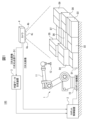
- FIG. 1 is a diagram showing an example of a schematic diagram of an entire robot system for explaining an example of a training data generating device according to the present embodiment.
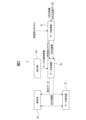
- FIG. 2 is a functional block diagram for explaining an example of a training data generating device according to this embodiment.
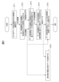
- FIG. 3 is a flowchart for explaining an example of processing in a first example of a learning data generation program according to this embodiment.
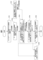
- FIG. 4 is a flowchart for explaining an example of processing in a second example of the learning data generation program according to this embodiment.
- FIG. 5 is a flowchart for explaining an example of processing in a third example of the learning data generation program according to this embodiment.
- FIG. 6 is a flowchart for explaining an example of processing in the fourth example of the learning data generation program according to this embodiment.
- FIG. 1 is a diagram showing an example of a schematic diagram of an entire robot system for explaining an example of a training data generating device according to the present embodiment.
- FIG. 2 is a functional block diagram for explaining an example of
- FIG. 7 is a diagram for explaining an example of a process of correcting teaching data by a user in the learning data generating method according to this embodiment.
- FIG. 8 is a flowchart for explaining an example of processing in the fifth example of the learning data generation program according to this embodiment.
- FIG. 9 is a diagram showing an example of a workpiece in a robot system in which an example of a learning data generating device according to this embodiment is used.
- FIG. 10 is a diagram for explaining the shape region of a workpiece in one example of the learning data generation device according to this embodiment.
- FIG. 1 is a schematic diagram showing an example of an entire robot system to explain an example of a learning data generation device according to this embodiment.
- the robot system 100 includes a robot 1, a robot control device 2, a learning data generation device 3, and a camera 4.
- the robot 1 includes a robot mechanism 10, an arm 11, and an end effector (hand) 12.
- a machine learning device for performing machine learning is not shown because it is built into the robot control device 2.
- the machine learning device can be configured, for example, as a dedicated workstation installed near the robot control device 2, or a higher-level computer or general-purpose computer installed in a location remote from the robot system 100.
- a general-purpose computer or processor may be used, but faster processing can be achieved by using a GPGPU (General-Purpose computing on Graphics Processing Units) or a large-scale PC cluster.
- the robot 1 is configured, for example, as a multi-axis robot, and an end effector 12 is provided at the tip of an arm 11.
- the end effector 12 is a suction device (suction hand), but it goes without saying that this can be changed to various types depending on the work (object) and work content used by the robot system 100.
- the robot mechanism unit 10 is for making the robot 1 perform a specified operation based on a control command from the robot control device 2.
- the robot control device 2 receives the output of the camera 4 and the output of the learning data generation device 3, and generates control commands for making the robot 1 perform a specified operation, for example based on a program or control data previously stored in an internal storage device, and outputs the generated control commands to the robot mechanism unit 10.
- the machine learning device that performs supervised learning does not need to be built into the robot control device 2, but may be provided separately, for example, near the robot control device 2 or at a location away from the robot system 100, depending on the amount of calculation and data.
- the learning data generating device 3 receives multiple images of the workpieces and generates teaching data (teacher data) including area information (information on the shape area of the workpieces) of the workpieces D1 to D9 in each image. Furthermore, the learning data generating device 3 outputs the generated teaching data and the corresponding images to the robot control device 2 (machine learning device) as learning data.
- the learning data generating device 3 receives image data of the workpieces D1 to D9 captured by the camera 4, but the image data provided to the learning data generating device 3 is not limited to images captured by the camera 4 of the robot system 100, and may be various image data such as images of the workpieces captured in advance or images obtained by other robot systems.
- the images input to the learning data generating device 3 are not limited to two-dimensional images, and as will be described in detail later, three-dimensional data (three-dimensional images, three-dimensional point cloud data, three-dimensional measurement data) may also be input together.
- the camera 4 is for acquiring a two-dimensional image of the area where multiple workpieces (e.g., multiple cardboard boxes) D1 to D9 are present, or a two-dimensional image and three-dimensional data (three-dimensional point cloud data), and includes two cameras 4a and 4b and a projector 4c.
- the projector 4c projects a predetermined pattern onto the area where multiple workpieces D1 to D9 are present, and the two cameras 4a and 4b capture the area where multiple workpieces are present onto which the predetermined pattern is projected by the projector 4c, and measure the three-dimensional shapes of the workpieces D1 to D9.
- the camera 4 may be configured to measure the three-dimensional shape of the area where multiple workpieces D1 to D9 are present and acquire three-dimensional point cloud data, but it can also be configured as a single two-dimensional camera, for example.
- the camera 4 in FIG. 1 is also configured to acquire a two-dimensional image of the area where multiple workpieces D1 to D9 are present, using an image captured by one of the two cameras 4a and 4b.
- the camera 4 only needs to be able to capture appropriate images according to, for example, the work or task being performed by the robot 1, or according to annotations in supervised learning.
- the training data generation device 3 that generates training data to be used in machine learning includes a data acquisition unit 31, a data processing unit (arithmetic processing device) 32, a data storage unit 33, a reception unit 34, and a display unit 35.
- the data acquisition unit 31 acquires images (two-dimensional images, or two-dimensional images and three-dimensional point cloud data) of the areas where multiple workpieces (D1 to D9) exist and a trained model.
- the data processing unit 32 at least estimates area information reflecting the entire or partial area range of at least one workpiece (D0, D) based on the images acquired by the data acquisition unit 31, and generates teaching data including the estimated area information.
- the trained model can be, for example, a training model generated by another training data generation device 3, or a training model (previous training model) generated by the training data generation device 3 itself. Note that, as will be described in detail later with reference to FIGS. 3 to 8, if a trained model is not used according to each example of this embodiment, the data acquisition unit 31 does not need to acquire the trained model. Similarly, if three-dimensional point cloud data is not used in each example according to this embodiment, the data acquisition unit 31 does not need to acquire the three-dimensional point cloud data.
- the area information of the workpiece (D0) includes, for example, at least one of outer shape area information reflecting the outer shape of the workpiece, removal area information for adsorbing, suctioning or gripping the workpiece, and local area information on the workpiece.
- the local area information of the workpiece (D0) includes, for example, at least one of flat surfaces, curved surfaces or areas with large areas on the workpiece, non-slip areas on the workpiece, and high density areas on the workpiece. This local area information of the workpiece will be described in detail later with reference to FIG. 9.
- the data storage unit 33 stores the teaching data and images (e.g., two-dimensional images, or two-dimensional images and three-dimensional point cloud data) generated by the data processing unit 32 as learning data.
- the reception unit 34 receives, for example, correction information based on area information of at least one workpiece input by a worker (user). At this time, the data processing unit 32 corrects and outputs the teaching data based on, for example, the correction information received by the reception unit 34.
- the display unit 35 displays the images and teaching data, and allows, for example, the user to make further corrections to the teaching data (learning data).
- the data processing unit 32 estimates area information of the workpiece based on the image and the trained model, and generates teaching data. Also, when the data acquisition unit 31 acquires two-dimensional images of the areas where multiple workpieces (D0 to D9, D) exist, the data processing unit 32 estimates area information based on the two-dimensional images acquired by the data acquisition unit 31, and generates teaching data. Furthermore, when the data acquisition unit 31 acquires two-dimensional images and three-dimensional data (three-dimensional point cloud data) of the areas where multiple workpieces (D0 to D9, D) exist, the data processing unit 32 estimates area information based on the two-dimensional images and three-dimensional point cloud data acquired by the data acquisition unit 31, and generates teaching data.
- the data processing unit 32 can estimate three-dimensional area information of the workpiece based on the results of at least one of the following analyses of the three-dimensional point cloud data: plane analysis, curved surface analysis, blob analysis, coordinate system analysis, attitude analysis, depth analysis, scale analysis, feature analysis, nearby point analysis, mesh analysis, and voxel analysis, and can compare the three-dimensional point cloud data with a two-dimensional image to estimate area information of the workpiece in the two-dimensional image and generate teaching data. Furthermore, the data processing unit 32 can correct and output the teaching data based on the area information of the workpiece estimated based on the analysis results of the three-dimensional point cloud data. The data processing unit 32 can also extract features by performing image processing based on the area information of at least one workpiece and the image received by the receiving unit 34, and can match the extracted features to estimate area information of the workpiece on the image and generate teaching data.
- the data processing unit 32 can perform image processing based on the image, and can estimate work area information based on the image and the results of the image processing to generate teaching data.
- the data processing unit 32 can also estimate work area information based on the results of at least one of the following image processing methods: pattern matching, plane matching, curved surface matching, blob analysis, feature analysis, gradient analysis, edge analysis, contrast analysis, histogram analysis, and color information analysis.
- the data processing unit 32 can correct and output teaching data based on the work area information estimated based on the results of the image processing.
- FIG. 9 is a diagram showing an example of a workpiece in a robot system in which an embodiment of the learning data generating device according to this embodiment is used.
- the workpiece (object) D0 to be worked on is not limited to rectangular parallelepiped objects made of the same material, such as the cardboard boxes D1 to D9 shown in FIG. 1, and various objects are possible. That is, the workpiece D0 shown in FIG. 9 is an air joint, in which areas Da, Db, and Dd are made of plastic (for example, PTFE: polytetrafluoroethylene) material, and area Dc is made of metal (for example, brass or stainless steel).
- plastic for example, PTFE: polytetrafluoroethylene
- the metal that forms area Dc has a higher specific gravity than the plastic that forms areas Da, Db, and Dd, and area Dc is designed to surround areas Db to Dd with a hexagonal plane to facilitate tightening work using a tool such as a wrench.
- the success rate of taking out the workpiece is higher when the suction hand 12 picks up the area Dc made of metal with high density (heavy) material rather than picking up the areas Da, Db, Dd made of plastic with low density (light) material, because the workpiece can be taken out at a position closer to the center of gravity of the entire workpiece D0.
- the suction hand 12 suctions the flat area Dc formed by the metal of the air joint D0, which is the workpiece, making it possible to stably remove the workpiece D0.
- the user refers to the image and teaching data displayed on the display unit 35 and correct the teaching data (learning data). Even in this case, the user only needs to perform some of the processing, which requires much less effort than the conventional method of manually clicking on an image to teach area information of an object.
- the area information of the workpiece D0 it is preferable for the area information of the workpiece D0 to include at least one of outer shape area information reflecting the outer shape of the workpiece D0, removal area information for adsorbing, suctioning or gripping the workpiece D0, and local area information on the workpiece D0.
- FIG. 10 is a diagram for explaining the shape region of a workpiece in one embodiment of the learning data generation device according to this embodiment, where FIG. 10(a) shows the shape region of the workpiece D, and FIG. 10(b) shows the region including the background of the workpiece D.
- the term "shape region of the workpiece” refers to the region indicated by reference character A1 (the region of the workpiece D itself) that includes only the workpiece D and does not include the background of the workpiece D in the two-dimensional image P3 output from the camera 4, as shown in FIG. 10(a), and is not the region that includes the workpiece D and the background as shown in FIG. 10(b).
- the "shape region of the workpiece” in this specification is "region information that reflects the shape/outer shape of the workpiece," and this information can be used to calculate the shape/outer shape of the workpiece.
- FIG. 3 is a flowchart for explaining an example of processing in a first example of the learning data generation program (learning data generation method) according to this embodiment, and shows a case where the data acquisition unit 31 acquires a two-dimensional image and a trained model.
- the camera 4 captures a two-dimensional image of the presence area of the workpiece D. That is, as described with reference to FIG. 1, the camera 4 captures two-dimensional images of the presence areas of the workpieces (e.g., multiple cardboard boxes) D1 to D9 and outputs them to the learning data generation device 3.
- the workpieces e.g., multiple cardboard boxes
- the data acquisition unit 31 acquires a two-dimensional image and a trained model and outputs them to the data processing unit 32.
- the two-dimensional image received by the data acquisition unit 31 is a two-dimensional image of the area in which the workpiece is present, as described with reference to FIG. 2.
- the trained model received by the data acquisition unit 31 can be, for example, one prepared in advance by the provider that offers the robot system.
- the trained model can be, for example, a training model generated by another training data generation device 3, or a training model (previous training model) generated by the training data generation device 3 itself.
- step ST13 the data processing unit 32 estimates the work area based on the two-dimensional image from the data acquisition unit 31 and the trained model
- step ST14 the data processing unit 32 generates teaching data (teacher data) based on the estimated information of the shape area of the workpiece D. That is, the data processing unit 32 estimates the shape area (area information) of the workpiece based on the two-dimensional image and the trained model, and generates teaching data.
- the shape area of the workpiece D corresponds to, for example, the shape area A1 in FIG. 10(a), as described with reference to FIG. 10.
- step ST16 is a process of displaying the two-dimensional image data from step ST12 and the teaching data from step ST14 on the display unit 35, and it is possible for the user to refer to the two-dimensional image and teaching data displayed on the display unit 35 and correct the teaching data, for example. It goes without saying that it is also possible to simply display the two-dimensional image and teaching data on the display unit 35 without performing any processing by the user.
- the process of step ST16 in this first embodiment is similar to steps ST26, ST36, ST47, and ST55 in each embodiment described below.
- learning data generation program (learning data generation method) of this first embodiment, learning data (teaching data) can be easily generated without incurring high labor costs and huge amounts of work time.
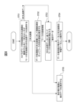
- FIG. 4 is a flowchart for explaining an example of processing in a second example of the learning data generation program according to this embodiment, showing a case in which the data acquisition unit 31 acquires a two-dimensional image and does not acquire a trained model.
- the camera 4 captures a two-dimensional image of the area in which the workpiece D (D1 to D9) is present.
- the process proceeds to step ST22, in which the data acquisition unit 31 acquires the two-dimensional image and outputs it to the data processing unit 32.
- the two-dimensional image received by the data acquisition unit 31 is a two-dimensional image of the area in which the workpiece is present, as described with reference to FIG. 2, captured by the camera 4.
- step ST23 the data processing unit 32 performs image processing on the two-dimensional image from the data acquisition unit 31 to estimate the shape area of the workpiece D.
- step ST24 the data processing unit 32 generates teaching data based on the estimated information on the shape area of the workpiece D.
- step ST25 the data storage unit 33 stores the teaching data and the two-dimensional image as learning data and ends the process (END).
- step ST26 corresponds to step ST16 in the first embodiment described above, and a description thereof will be omitted.
- the training data generation program of this second embodiment does not use the trained model in the first embodiment described above, making it possible to simplify processing.
- a trained model since a trained model is not used, there is a risk that the accuracy of the teaching data will be somewhat inferior to that of the first embodiment. For this reason, it is preferable to determine whether to implement this second embodiment based on the shape of the target workpiece, the content of the work, or the time it takes to actually start operating the robot system, etc.
- FIG. 5 is a flowchart for explaining an example of processing in a third example of the learning data generation program according to this embodiment, showing a case in which the data acquisition unit 31 acquires only a two-dimensional image and does not acquire a learned model, the reception unit 34 accepts area information (shape area) of the workpiece, and the data processing unit 32 performs image processing.
- the camera 4 captures a two-dimensional image of the area in which the workpiece D exists.
- the process proceeds to step ST32, where the data acquisition unit 31 acquires the two-dimensional image and outputs it to the data processing unit 32.
- step ST33 the data processing unit 32 performs image processing based on the two-dimensional image from the data acquisition unit 31 and the area information of the workpiece D, and estimates the shape area of all (multiple) works D1 to D9 (D0, D) on the image.
- the image processing performed by the data processing unit 32 is, for example, at least one of pattern matching, plane matching, curved surface matching, blob analysis, feature analysis, gradient analysis, edge analysis, contrast analysis, histogram analysis, and color information analysis.
- FIG. 6 is a flowchart for explaining an example of processing in the fourth example of the learning data generation program according to this embodiment, showing a case where the data acquisition unit 31 acquires a two-dimensional image and a trained model, and the user modifies the teaching data.
- the camera 4 captures a two-dimensional image of the area in which the work D exists.
- the process proceeds to step ST42, where the data acquisition unit 31 acquires the two-dimensional image and the trained model, and outputs them to the data processing unit 32.
- step ST43 the data processing unit 32 estimates the shape area of the workpiece D based on the two-dimensional image from the data acquisition unit 31 and the trained model, and the process proceeds to step ST44.
- step ST44 the data processing unit 32 generates teaching data based on the estimated information of the shape area of the workpiece D.
- FIG. 7 is a diagram for explaining an example of a user-initiated correction process for teaching data in the learning data generation method according to this embodiment.
- the upper part of FIG. 7(a), FIG. 7(b), and FIG. 7(c) show cases where the teaching data is correct and the user does not need to correct the teaching data
- the lower part of FIG. 7(d), FIG. 7(e), and FIG. 7(f) show cases where the teaching data is incorrect and the user needs to correct the teaching data.
- FIG. 7(a) and FIG. 7(d) are two-dimensional images of multiple workpieces
- FIG. 7(b) and FIG. 7(e) are images showing the results of contour extraction by image processing superimposed on the two-dimensional images
- FIG. 7(c) and FIG. 7(f) are images showing the final teaching results (final learning data).
- a camera 4 is used to capture an image of an area where multiple workpieces (e.g., multiple cardboard boxes) are lined up, and while changing the arrangement of the workpieces, multiple two-dimensional images are captured of the area where multiple workpieces are lined up in different arrangements (Figs. 7(a) and 7(d)).
- image processing is performed on each image, and the characteristics of the contour line of each workpiece in each image are extracted (Figs. 7(b) and 7(e)).
- the contour line can be extracted, for example, by binarizing the two-dimensional image to generate a black and white image, and then searching for and finding the boundary line between black and white on the image. Note that, for example, when the workpiece is a cardboard box, the color within the workpiece area is almost uniform, and the greater the color difference between the workpiece area and the background area, the more accurately the contour line of the workpiece can be found.
- the contour lines extracted by image processing are correct, for example, the case where image processing is performed on the captured image of workpieces a11 to a14 as shown in FIG. 7(a), and the characteristics of the contour lines of workpieces b11 to b14 as shown in FIG. 7(b) are extracted.
- the user looks at (refers to) the two-dimensional image of the workpiece and the image of the teaching data as shown in FIG. 7(b) displayed on the display unit 35.
- the user judges whether the learning data (two-dimensional image and teaching data) as shown in FIG.
- the left and lower contours of workpiece e13 cannot be recognized by image processing, and the contour between workpieces e12 and e14 cannot be recognized by image processing, and they are erroneously determined as one workpiece.
- the user will see the two-dimensional image of the workpiece displayed on the display unit 35 and the image of the teaching data as shown in FIG. 7(e). The user will then determine whether the learning data (two-dimensional image and teaching data) as shown in FIG. 7(e) displayed on the display unit 35 is correct.
- the missing contour line in e13 is added by clicking with a mouse or the like to correct it to the area where the workpiece exists, and correction is made. Furthermore, if the user judges that e12 and e14 in FIG. 7(e) are not one workpiece but two works, the missing boundary line between e12 and e14 is added by operating a mouse or the like to correct it to two works. Furthermore, if the user judges that the contour line of the label in the area e11 in FIG.
- the final learning data (instruction data f11 to f14) corrected by the user as shown in FIG. 7(f) is obtained, and this learning data is stored in the data storage unit 33.
- the correction of the instruction data by the user is preferably used, for example, as described with reference to FIG. 9, for determining areas of metal and plastic materials that can be immediately determined by the user (person) by referring to an image (e.g., a color image or a grayscale image).
- FIG. 8 is a flowchart for explaining an example of processing in the fifth embodiment of the learning data generation program according to this embodiment.
- the camera 4 captures a two-dimensional image of the area in which the workpiece D exists, and the three-dimensional sensor acquires three-dimensional point cloud data (three-dimensional data) of the area in which the workpiece D exists.
- the process proceeds to step ST52, where the data acquisition unit 31 performs image processing on the two-dimensional image to estimate the shape area.
- step ST53 where the area information of work D is corrected based on the three-dimensional point cloud data.
- correcting the area information of work D based on the three-dimensional point cloud data means, for example, comparing the three-dimensional point cloud data with the two-dimensional images for the calculation results of the shape area in each of the two-dimensional images of multiple workpieces. Furthermore, by utilizing the difference in three-dimensional position contained in the three-dimensional point cloud data, background areas, obstacle areas, areas of adjacent workpieces, etc. that are erroneously included in the calculation results are excluded, and the corrected teaching data for the work is obtained.
- step ST54 the data storage unit 33 stores the teaching data and the two-dimensional image as learning data, and the process ends (END).
- the process ends (END).
- step ST55 also corresponds to, for example, step ST47 in the fourth embodiment described with reference to FIG. 6, and as described above, the processes of steps ST45 and ST46 in the fourth embodiment can be additionally performed.
- the learning data generation program according to the present embodiment described above may be provided by recording it on a computer-readable non-transitory recording medium or a non-volatile semiconductor memory, or may be provided via a wired or wireless connection.
- Examples of computer-readable non-transitory recording media include optical discs such as CD-ROMs (Compact Disc Read Only Memory) and DVD-ROMs, or hard disk devices.
- Examples of non-volatile semiconductor memory include PROMs (Programmable Read Only Memory) and flash memories.
- distribution from a server device may be via a wired or wireless LAN (Local Area Network), or a WAN such as the Internet.
- the learning data generation device, robot system, learning data generation method, and learning data generation program according to this embodiment make it possible to perform annotation without incurring high labor costs and huge amounts of work time.
- a learning data generation device (3) for generating learning data for use in machine learning comprising: A data acquisition unit (31) that acquires images of areas where a plurality of workpieces (D0 to D9, D) are present; A data processing unit (32) that at least estimates area information reflecting a whole or part of an area range of at least one of the workpieces (D0, D) based on the acquired image, and generates teaching data including the estimated area information; a data storage unit (33) that stores the generated teaching data and the image as the learning data; A training data generating device comprising: [Appendix 2] The learning data generation device described in Appendix 1, wherein the area information of the workpiece (D0, D) includes at least one of outer shape area information reflecting the outer shape of the workpiece (D0, D), removal area information for adsorbing, suctioning or grasping the workpiece (D0, D), and local area information on the workpiece (D0, D
- [Appendix 3] The learning data generation device described in Appendix 2, wherein the local area information of the workpiece (D0, D) includes at least one of a flat surface, a curved surface, or a large area on the workpiece (D0, D), a non-slip area on the workpiece (D0, D), and a high-density area on the workpiece (D0, D).
- a reception unit (34) is provided, The reception unit (34) receives correction information based on area information of at least one of the works (D0, D),
- the learning data generating device according to any one of claims 1 to 3, wherein the data processing unit (32) modifies and outputs the teaching data based on the teaching information accepted by the accepting unit (34).
- the data acquisition unit (31) further acquires a trained model
- the data processing unit (32) estimates area information of the work (D0, D) based on the image and the trained model, and generates the teaching data.
- the data acquisition unit (31) acquires a two-dimensional image of an area where the plurality of workpieces (D0 to D9, D) are present,
- the learning data generation device according to any one of Supplementary Note 1 to Supplementary Note 5, wherein the data processing unit (32) estimates the region information based on the two-dimensional image and generates the teaching data.
- the data acquisition unit (31) acquires two-dimensional images and three-dimensional data of the areas in which the plurality of workpieces (D0 to D9, D) are present, The learning data generation device according to any one of Supplementary Note 1 to Supplementary Note 5, wherein the data processing unit (32) estimates the region information based on the two-dimensional image and the three-dimensional data, and generates the teaching data.
- the data processing unit (32) analyzes the three-dimensional data, estimates three-dimensional area information of the workpiece based on the analysis results, compares the three-dimensional data with the two-dimensional image to estimate area information of the workpiece in the two-dimensional image, and generates the teaching data.
- [Appendix 9] The learning data generation device described in Appendix 8, wherein the data processing unit (32) estimates three-dimensional region information of the work (D0, D) based on the processing results of at least one of plane analysis, curved surface analysis, blob analysis, coordinate system analysis, posture analysis, depth analysis, scale analysis, feature analysis, nearby point analysis, mesh analysis, and voxel analysis as an analysis of the three-dimensional data.
- [Appendix 10] The learning data generation device described in Appendix 8 or Appendix 9, wherein the data processing unit (32) modifies and outputs the teaching data based on area information of the work (D0, D) estimated based on the analysis results of the three-dimensional data.
- the data processing unit (32) performs image processing based on area information of at least one of the works (D0, D) received by the receiving unit (34) and the image to extract features, performs matching processing of the extracted features to estimate area information of multiple works (D0, D) on the image, and generates the teaching data.
- the data processing unit (32) performs image processing based on the image, and estimates area information of the work (D0, D) based on a result of the image processing and the image, thereby generating the teaching data.
- [Appendix 13] The learning data generation device according to claim 11 or 12, wherein the data processing unit (32) estimates area information of the work (D0, D) based on the results of processing performed as the image processing at least one of pattern matching, plane matching, curved surface matching, blob analysis, feature analysis, gradient analysis, edge analysis, contrast analysis, histogram analysis, and color information analysis.
- the data processing unit (32) corrects and outputs the teaching data based on area information of the work (D0, D) estimated based on the processing result of the image processing.
- a display unit (35) is provided, The learning data generation device according to any one of claims 1 to 14, wherein the display unit (35) displays the image and the teaching data.
- [Appendix 16] The learning data generation device described in Appendix 15, wherein the data processing unit (32) includes a process of correcting the teaching data by referring to the image and the teaching data displayed on the display unit (35).
- a robot (1) that performs a predetermined process on a plurality of the workpieces (D0 to D9, D);
- a camera (4) that captures an image of an area where the plurality of works (D0 to D9, D) are present and outputs the image;
- a learning data generation device (3) according to any one of Supplementary Note 1 to Supplementary Note 16, which receives the image from the camera (4) and outputs the learning data; a machine learning device that receives the learning data from the learning data generation device (3) and performs machine learning;
- a robot system (100) comprising: a robot control device (2) that receives output from the machine learning device and controls the robot (1).
- a learning data generation method for generating learning data for use in machine learning comprising: A data acquisition process for acquiring images of the areas where a plurality of workpieces (D0 to D9, D) are present; A data processing step of estimating at least area information reflecting the entire or partial area range of at least one of the workpieces (D0, D) based on the acquired image, and generating teaching data including the estimated area information; a data storage step of storing the generated teaching data and the image as the learning data; A learning data generation method comprising: [Appendix 19] The data acquisition step further includes acquiring a trained model that has been trained and generated in advance, The learning data generation method described in Appendix 18, wherein the data processing step estimates region information of the work (D0, D) based on the image and the trained model, and generates the teaching data.
- the method further includes a receiving step, in which area information of at least one of the works (D0, D) is received,
- the data processing step comprises performing image processing based on the received area information and the image for a plurality of the workpieces (D0 to D9, D) to extract features, performing a matching process for the extracted features, and estimating area information for the plurality of workpieces (D0 to D9, D) on the image to generate the teaching data.
- the data processing step performs image processing based on the image, and estimates area information of the work (D0 to D9, D) based on a processing result of the image processing and the image to generate the teaching data.
- the data acquisition step further acquires two-dimensional images and three-dimensional data of the areas where the plurality of workpieces (D0 to D9, D) are present, 22.
- the learning data generation method according to any one of claims 18 to 21, wherein the data processing step estimates the region information based on the two-dimensional image and the three-dimensional data, and generates the teaching data.
- the method further includes a receiving step, in which correction information based on area information of at least one of the works (D0, D) is received; 23.
- the learning data generating method according to any one of claims 18 to 22, wherein the data processing step corrects the teaching data based on the received correction information.
- a learning data generation program for generating learning data for use in machine learning A processing unit, A data acquisition process for acquiring images of the areas where a plurality of workpieces (D0 to D9, D) are present; A data processing step of estimating at least area information reflecting the entire or partial area range of at least one of the workpieces (D0, D) based on the acquired image, and generating teaching data including the estimated area information; and a data storage step of storing the generated teaching data and the image as the learning data.
Landscapes
- Engineering & Computer Science (AREA)
- Theoretical Computer Science (AREA)
- Physics & Mathematics (AREA)
- Software Systems (AREA)
- Computing Systems (AREA)
- Artificial Intelligence (AREA)
- Mathematical Physics (AREA)
- General Physics & Mathematics (AREA)
- Data Mining & Analysis (AREA)
- Evolutionary Computation (AREA)
- General Engineering & Computer Science (AREA)
- Biomedical Technology (AREA)
- Molecular Biology (AREA)
- General Health & Medical Sciences (AREA)
- Computational Linguistics (AREA)
- Biophysics (AREA)
- Life Sciences & Earth Sciences (AREA)
- Health & Medical Sciences (AREA)
- Computer Vision & Pattern Recognition (AREA)
- Medical Informatics (AREA)
- Image Analysis (AREA)
- Manipulator (AREA)
- Numerical Control (AREA)
Abstract
Priority Applications (5)
| Application Number | Priority Date | Filing Date | Title |
|---|---|---|---|
| PCT/JP2023/012217 WO2024201655A1 (fr) | 2023-03-27 | 2023-03-27 | Dispositif de génération de données d'apprentissage, système de robot, procédé de génération de données d'apprentissage et programme de génération de données d'apprentissage |
| JP2025509286A JPWO2024201655A1 (fr) | 2023-03-27 | 2023-03-27 | |
| CN202380091086.0A CN120530406A (zh) | 2023-03-27 | 2023-03-27 | 学习数据生成装置、机器人系统、学习数据生成方法以及学习数据生成程序 |
| DE112023005644.7T DE112023005644T5 (de) | 2023-03-27 | 2023-03-27 | Lerndaten-Erzeugungsvorrichtung, Robotersystem, Lerndaten-Erzeugungsverfahren und Lerndaten-Erzeugungsprogramm |
| TW113107018A TW202439201A (zh) | 2023-03-27 | 2024-02-27 | 學習資料生成裝置、機器人系統、學習資料生成方法及學習資料生成程式 |
Applications Claiming Priority (1)
| Application Number | Priority Date | Filing Date | Title |
|---|---|---|---|
| PCT/JP2023/012217 WO2024201655A1 (fr) | 2023-03-27 | 2023-03-27 | Dispositif de génération de données d'apprentissage, système de robot, procédé de génération de données d'apprentissage et programme de génération de données d'apprentissage |
Publications (1)
| Publication Number | Publication Date |
|---|---|
| WO2024201655A1 true WO2024201655A1 (fr) | 2024-10-03 |
Family
ID=92904048
Family Applications (1)
| Application Number | Title | Priority Date | Filing Date |
|---|---|---|---|
| PCT/JP2023/012217 Ceased WO2024201655A1 (fr) | 2023-03-27 | 2023-03-27 | Dispositif de génération de données d'apprentissage, système de robot, procédé de génération de données d'apprentissage et programme de génération de données d'apprentissage |
Country Status (5)
| Country | Link |
|---|---|
| JP (1) | JPWO2024201655A1 (fr) |
| CN (1) | CN120530406A (fr) |
| DE (1) | DE112023005644T5 (fr) |
| TW (1) | TW202439201A (fr) |
| WO (1) | WO2024201655A1 (fr) |
Citations (3)
| Publication number | Priority date | Publication date | Assignee | Title |
|---|---|---|---|---|
| JP2019056966A (ja) * | 2017-09-19 | 2019-04-11 | 株式会社東芝 | 情報処理装置、画像認識方法および画像認識プログラム |
| JP2019058960A (ja) * | 2017-09-25 | 2019-04-18 | ファナック株式会社 | ロボットシステム及びワーク取り出し方法 |
| WO2023286847A1 (fr) * | 2021-07-15 | 2023-01-19 | 京セラ株式会社 | Procédé de génération de modèle de reconnaissance et dispositif de génération de modèle de reconnaissance |
-
2023
- 2023-03-27 WO PCT/JP2023/012217 patent/WO2024201655A1/fr not_active Ceased
- 2023-03-27 CN CN202380091086.0A patent/CN120530406A/zh active Pending
- 2023-03-27 DE DE112023005644.7T patent/DE112023005644T5/de active Pending
- 2023-03-27 JP JP2025509286A patent/JPWO2024201655A1/ja active Pending
-
2024
- 2024-02-27 TW TW113107018A patent/TW202439201A/zh unknown
Patent Citations (3)
| Publication number | Priority date | Publication date | Assignee | Title |
|---|---|---|---|---|
| JP2019056966A (ja) * | 2017-09-19 | 2019-04-11 | 株式会社東芝 | 情報処理装置、画像認識方法および画像認識プログラム |
| JP2019058960A (ja) * | 2017-09-25 | 2019-04-18 | ファナック株式会社 | ロボットシステム及びワーク取り出し方法 |
| WO2023286847A1 (fr) * | 2021-07-15 | 2023-01-19 | 京セラ株式会社 | Procédé de génération de modèle de reconnaissance et dispositif de génération de modèle de reconnaissance |
Also Published As
| Publication number | Publication date |
|---|---|
| JPWO2024201655A1 (fr) | 2024-10-03 |
| TW202439201A (zh) | 2024-10-01 |
| DE112023005644T5 (de) | 2025-12-24 |
| CN120530406A (zh) | 2025-08-22 |
Similar Documents
| Publication | Publication Date | Title |
|---|---|---|
| NL2024682B1 (en) | Assembly monitoring method and device based on deep learning, and readable storage medium | |
| CN103577793B (zh) | 手势识别方法及装置 | |
| JP5521628B2 (ja) | モデルを定義するプログラム及びシステム | |
| CN111402336A (zh) | 基于语义slam的动态环境相机位姿估计及语义地图构建方法 | |
| Prankl et al. | RGB-D object modelling for object recognition and tracking | |
| Alvarez et al. | Providing guidance for maintenance operations using automatic markerless augmented reality system | |
| CN117769724A (zh) | 使用深度学习的对象检测和分类的合成数据集创建 | |
| CN118071968B (zh) | 一种基于ar技术的智能交互深展示方法及系统 | |
| CN107564004B (zh) | 一种基于计算机辅助跟踪的篡改视频标注方法 | |
| WO2021188104A1 (fr) | Estimation de pose d'objet et détection de défauts | |
| CN118196448A (zh) | 基于场景语义图的视觉重定位方法、装置和计算机设备 | |
| CN114299109B (zh) | 多目标对象轨迹生成方法、系统、电子设备和存储介质 | |
| Patten et al. | Object learning for 6D pose estimation and grasping from RGB-D videos of in-hand manipulation | |
| Naumann et al. | Scrape, cut, paste and learn: Automated dataset generation applied to parcel logistics | |
| WO2024201655A1 (fr) | Dispositif de génération de données d'apprentissage, système de robot, procédé de génération de données d'apprentissage et programme de génération de données d'apprentissage | |
| Wolnitza et al. | 6D pose estimation and 3D object reconstruction from 2D shape for robotic grasping of objects | |
| CN119379794B (zh) | 一种基于深度学习的机器人姿态估计方法 | |
| WO2024188414A1 (fr) | Système et procédé d'identification d'objet | |
| US20230215040A1 (en) | Method and system for tracking a cad model in real time based on particle filters | |
| CN112102502A (zh) | 用于飞机驾驶舱功能试验的增强现实辅助方法 | |
| KR102800405B1 (ko) | 컴퓨터 비전을 활용한 로봇팔 티칭 장치 및 방법 | |
| CN118859238B (zh) | 基于slam和ai的地下管廊设备三维数据采集方法 | |
| CN116962817B (zh) | 视频处理方法、装置、电子设备及存储介质 | |
| US20260105633A1 (en) | Recognition device, model generation device, and work system | |
| Blomqvist et al. | 3D Annotation Of Arbitrary Objects In The Wild |
Legal Events
| Date | Code | Title | Description |
|---|---|---|---|
| 121 | Ep: the epo has been informed by wipo that ep was designated in this application |
Ref document number: 23930295 Country of ref document: EP Kind code of ref document: A1 |
|
| WWE | Wipo information: entry into national phase |
Ref document number: 2025509286 Country of ref document: JP |
|
| WWE | Wipo information: entry into national phase |
Ref document number: 202380091086.0 Country of ref document: CN |
|
| WWP | Wipo information: published in national office |
Ref document number: 202380091086.0 Country of ref document: CN |
|
| WWE | Wipo information: entry into national phase |
Ref document number: 112023005644 Country of ref document: DE |
|
| WWP | Wipo information: published in national office |
Ref document number: 112023005644 Country of ref document: DE |
|
| 122 | Ep: pct application non-entry in european phase |
Ref document number: 23930295 Country of ref document: EP Kind code of ref document: A1 |