WO2024201737A1 - Dispositif de commande de robot, procédé de commande de robot et programme - Google Patents
Dispositif de commande de robot, procédé de commande de robot et programme Download PDFInfo
- Publication number
- WO2024201737A1 WO2024201737A1 PCT/JP2023/012613 JP2023012613W WO2024201737A1 WO 2024201737 A1 WO2024201737 A1 WO 2024201737A1 JP 2023012613 W JP2023012613 W JP 2023012613W WO 2024201737 A1 WO2024201737 A1 WO 2024201737A1
- Authority
- WO
- WIPO (PCT)
- Prior art keywords
- movable part
- robot
- image
- correspondence relationship
- detection target
- Prior art date
- Legal status (The legal status is an assumption and is not a legal conclusion. Google has not performed a legal analysis and makes no representation as to the accuracy of the status listed.)
- Ceased
Links
Images




Classifications
-
- B—PERFORMING OPERATIONS; TRANSPORTING
- B25—HAND TOOLS; PORTABLE POWER-DRIVEN TOOLS; MANIPULATORS
- B25J—MANIPULATORS; CHAMBERS PROVIDED WITH MANIPULATION DEVICES
- B25J19/00—Accessories fitted to manipulators, e.g. for monitoring, for viewing; Safety devices combined with or specially adapted for use in connection with manipulators
- B25J19/02—Sensing devices
- B25J19/021—Optical sensing devices
- B25J19/023—Optical sensing devices including video camera means
-
- B—PERFORMING OPERATIONS; TRANSPORTING
- B25—HAND TOOLS; PORTABLE POWER-DRIVEN TOOLS; MANIPULATORS
- B25J—MANIPULATORS; CHAMBERS PROVIDED WITH MANIPULATION DEVICES
- B25J9/00—Program-controlled manipulators
- B25J9/16—Program controls
- B25J9/1656—Program controls characterised by programming, planning systems for manipulators
-
- B—PERFORMING OPERATIONS; TRANSPORTING
- B25—HAND TOOLS; PORTABLE POWER-DRIVEN TOOLS; MANIPULATORS
- B25J—MANIPULATORS; CHAMBERS PROVIDED WITH MANIPULATION DEVICES
- B25J9/00—Program-controlled manipulators
- B25J9/16—Program controls
- B25J9/1694—Program controls characterised by use of sensors other than normal servo-feedback from position, speed or acceleration sensors, perception control, multi-sensor controlled systems, sensor fusion
- B25J9/1697—Vision controlled systems
Definitions
- This disclosure relates to a robot control device, a robot control method, and a program.
- a single visual sensor e.g., a two-dimensional camera
- the moving part of the robot e.g., a hand, end effector, etc.
- the appearance of the detection target on the workpiece being transported in the transport direction which is included in the image generated by the visual sensor, changes. If the appearance of the detection target included in the image changes, there is a risk that the moving part of the robot cannot be made to properly follow the workpiece being transported in the transport direction with conventional visual feedback that uses a single visual sensor.
- One aspect of the present disclosure is a robot control device that includes an image acquisition unit that acquires image data including a detection target on a workpiece moving in a conveying direction, generated by a visual sensor provided on a movable part of a robot; a storage unit that stores at least a first correspondence relationship that is a correspondence relationship between a first position of the movable part in an optical axis direction of the visual sensor, which is a direction intersecting the conveying direction, and a first detection target position that is a target position on the image where the detection target should be located when the movable part is located at the first position; and a second correspondence relationship that is a correspondence relationship between a second position of the movable part in the optical axis direction and a second detection target position that is a target position on the image where the detection target should be located when the movable part is located at the second position; and a target position setting unit that sets the target position on the image where the detection target should be located based on the first correspondence relationship, the second correspondence relationship, and the position
- FIG. 1 is a diagram illustrating an example of a robot system 100 to which a robot control device 2 of a first embodiment is applied.
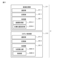
- FIG. 2 is a diagram illustrating an example of functional blocks of the robot system 100 shown in FIG. 1 .
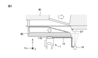
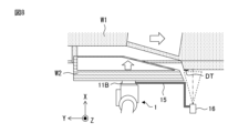
- FIG. 2 is a diagram showing a robot 1 and the like included in the robot system 100 shown in FIG. 1 as viewed from the top of FIG. 13 is a diagram for explaining an example of robot teaching executed at a movement start position X1 in the X direction of a movable part 11B (hand) of the robot 1.
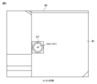
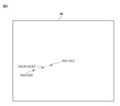
- FIG. 5 is a diagram showing an example of an image IM captured by a visual sensor 14 (two-dimensional camera) in the robot teaching shown in FIG. 4.
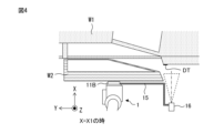
- FIG. 13 is a diagram for explaining an example of robot teaching executed at a movement end position X2 in the X direction of a movable part 11B (hand) of the robot 1.
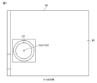
- FIG. 7 is a diagram showing an example of an image IM captured by a visual sensor 14 (two-dimensional camera) in the robot teaching shown in FIG. 6.
- 13 is a diagram for explaining an example of control (visual feedback) of the position of the movable part 11B (hand) of the robot 1 executed by the robot control unit 232.
- FIG. 9 is a diagram showing an example of the target position (Hz(X), Vt(X)) of the detection target DT on the image IM that is set by the target position setting unit 231B when the visual feedback shown in FIG. 8 is executed.
- FIG. 4 is a flowchart illustrating an example of a process executed by the robot control device 2 of the first embodiment.
- FIG. 13 is a diagram illustrating an example of a robot control device 2 according to a second embodiment.
- Fig. 1 is a diagram showing an example of a robot system 100 to which a robot control device 2 according to a first embodiment is applied.
- Fig. 2 is a diagram showing an example of functional blocks of the robot system 100 shown in Fig. 1.
- Fig. 3 is a diagram showing a robot 1 and the like included in the robot system 100 shown in Fig. 1 as viewed from the top of Fig. 1.
- a robot system 100 includes a robot 1 and a robot control device 2 .
- the robot system 100 does not include a teaching pendant, but in other examples, the robot system 100 may include a teaching pendant.
- the robot 1 is a six-axis vertical articulated robot.
- the robot 1 includes a plurality of links 11, a plurality of joints 12, a plurality of actuators 13, a visual sensor 14, and a connecting member 15.
- the multiple link parts 11 include a base part 11A, multiple movable parts 11C, and a movable part 11B.
- the multiple movable parts 11C include a part that functions as the torso of the robot 1 and a part that functions as the lower arm of the robot 1.
- the multiple movable parts 11C also include a part that functions as the upper arm of the robot 1 (more specifically, a part on the lower arm side of the upper arm of the robot 1 and a part on the wrist side of the upper arm of the robot 1).
- the multiple movable parts 11C also include a part that functions as the wrist of the robot 1 (more specifically, a part on the upper arm side of the wrist of the robot 1).
- the movable part 11B includes a part (hand) on the tip side of the wrist of the robot 1.
- the joints 12 include a joint 12 that connects the base 11A and the movable part 11C that functions as the torso of the robot 1.
- the joints 12 also include a joint 12 that connects the movable part 11C that functions as the torso of the robot 1 and the movable part 11C that functions as the lower arm of the robot 1.
- the joints 12 also include a joint 12 that connects the movable part 11C that functions as the lower arm of the robot 1 and the movable part 11C that functions as a part of the lower arm side of the upper arm of the robot 1.
- the joints 12 also include a joint 12 that connects the movable part 11C that functions as a part of the lower arm side of the upper arm of the robot 1 and the movable part 11C that functions as a part of the wrist side of the upper arm of the robot 1.
- the joints 12 also include a joint 12 that connects the movable part 11C that functions as a part of the wrist side of the upper arm of the robot 1 and the movable part 11C that functions as a part of the upper arm side of the wrist of the robot 1.
- the multiple joint parts 12 also include a joint part 12 that connects a movable part 11C that functions as the upper arm side part of the wrist of the robot 1 and a movable part 11B (hand) that functions as the tip side part of the wrist of the robot 1.
- the joint portion 12 may function as a linear joint.
- the actuators 13 include an actuator 13 that rotates (turns) the movable part 11C that functions as the body of the robot 1 with respect to the base part 11A.
- the actuators 13 also include an actuator 13 that rotates the movable part 11C that functions as the lower arm of the robot 1 with respect to the movable part 11C that functions as the body of the robot 1.
- the actuators 13 also include an actuator 13 that rotates the movable part 11C that functions as the lower arm side part of the upper arm of the robot 1 with respect to the movable part 11C that functions as the lower arm side part of the upper arm of the robot 1.
- the actuators 13 also include an actuator 13 that rotates the movable part 11C that functions as the wrist side part of the upper arm of the robot 1 with respect to the movable part 11C that functions as the lower arm side part of the upper arm of the robot 1 (i.e., twists the upper arm of the robot 1).
- the actuators 13 also include an actuator 13 that rotates the movable part 11C that functions as the upper arm side part of the wrist of the robot 1 with respect to the movable part 11C that functions as the wrist side part of the upper arm of the robot 1.
- the multiple actuators 13 also include an actuator 13 that rotates movable part 11B (hand) that functions as the tip side part of the wrist of robot 1 relative to movable part 11C that functions as the upper arm side part of the wrist of robot 1 (i.e., twists the wrist of robot 1).
- Each of the multiple actuators 13 is composed of a servo motor.
- the servo motor rotates a rotation shaft of the servo motor based on a control signal from the robot control device 2.
- Each of the multiple actuators 13 (servo motor) has an actuator sensor 13A.
- the actuator sensor 13A is composed of an encoder that detects the position and speed of the rotation shaft of the servo motor.
- the actuator sensor 13A (encoder) outputs actuator sensor data indicating the position and speed of the rotation shaft of the servo motor to the robot control device 2.
- an actuator other than a servo motor may be used as the actuator 13
- an actuator sensor other than an encoder may be used as the actuator sensor 13A.
- the visual sensor 14 is a two-dimensional camera.
- the two-dimensional camera captures an image IM (see FIG. 5, etc.) including a detection target DT on a workpiece W1 being transported in a transport direction (negative side of the Y direction, the front side in FIG. 1, the right side in FIG. 3) by a conveyor C.
- the visual sensor 14 generates data of the image IM including the detection target DT on the workpiece W1 moving in the transport direction and transmits it to the robot control device 2.
- the visual sensor 14 is connected to the movable part 11B (hand) that functions as the tip side part of the wrist of the robot 1 via a connection member 15.
- the visual sensor 14 moves integrally with the movable part 11B (hand).
- the visual sensor 14 is provided on the movable part 11B (hand) of the robot 1.
- the optical axis direction of the visual sensor 14 is set to the X direction. That is, the optical axis direction of the visual sensor 14 is a direction intersecting the conveying direction (Y direction) of the workpiece W1, for example, a direction approximately perpendicular to the conveying direction (Y direction) of the workpiece W1.
- the optical axis of the visual sensor 14 and the conveyor C conveying the workpiece W1 may cross each other, for example, at a three-dimensional intersection (that is, the optical axis of the visual sensor 14 and the conveyor C conveying the workpiece W1 may have a relationship of, for example, a "twist position").
- the optical axis direction of the visual sensor 14 and the conveying direction of the workpiece W1 are not limited to being approximately perpendicular, and may include a slight angular deviation.
- the visual sensor 14 is connected to the movable part 11B (hand) that functions as a part on the tip side of the wrist of the robot 1 via the connection member 15.
- the visual sensor 14 may be connected to a movable part 11C other than the movable part 11B (hand) of the robot 1 via the connection member 15.
- the visual sensor 14 may be connected to the movable part 11C that functions as a part on the upper arm side of the wrist of the robot 1 via the connection member 15.
- the robot control device 2 is configured by a computer having a communication unit 21, a storage unit 22, and a processing unit .
- the communication unit 21 is a communication interface and has an interface circuit for connecting the robot control device 2 to the actuator 13, visual sensor 14, etc. of the robot 1 via, for example, a signal line.
- the storage unit 22 is a memory such as a ROM (Read Only Memory) or a RAM (Random Access Memory), or a storage such as a HDD (Hard Disk Drive) or an SDD (Solid State Drive).
- the storage unit 22 stores programs and various data used in the processing executed by the processing unit 23.
- the processing unit 23 is a processor and has a function as an image processing unit 231 and a function as a robot control unit 232.
- the image processing unit 231 processes the image IM captured by the visual sensor 14 (two-dimensional camera), etc.
- the robot control unit 232 controls the robot 1 (visual feedback) based on the image IM captured by the visual sensor 14 (two-dimensional camera).
- the image processing unit 231 has a function as an image acquisition unit 231A and a function as a target position setting unit 231B.
- the image acquisition unit 231A acquires data of an image IM (see FIG. 5, etc.) including a detection target DT on a workpiece W1 moving in a conveying direction (right side in FIG. 3) generated by the visual sensor 14. That is, the image acquisition unit 231A acquires data of the image IM captured by the visual sensor 14 (two-dimensional camera).
- the target position setting unit 231B sets a target position (Hz(X), Vt(X)) (see FIG. 9) of the detection target DT on the image IM captured by the visual sensor 14 (two-dimensional camera), which is used in the visual feedback executed by the robot control unit 232.
- the target position setting unit 231B sets the target position (Hz(X), Vt(X)) of the detection target DT on the image IM when the position (actual coordinate value) in the X direction of the movable part 11B (hand) of the robot 1 calculated by the position calculation unit 232A described later is X.
- the robot control unit 232 has a function as a position calculation unit 232A and a function as a control unit 232B.
- the position calculation unit 232A calculates the position (more specifically, the position in the X-direction, Y-direction, and Z-direction (X, Y, Z)) of the movable part 11B (hand) of the robot 1 connected to the visual sensor 14 via the connecting member 15, based on the position of the rotation axis of each of the multiple actuators 13 (servo motors) detected by each of the multiple actuator sensors 13A (encoders).
- the control unit 232B executes control (visual feedback) of the position (X, Y, Z) of the movable part 11B (hand) of the robot 1 connected to the visual sensor 14 via the connecting member 15, based on the target position (Hz(X), Vt(X)) of the detection target DT on the image IM set by the target position setting unit 231B.
- control unit 232B executes control to move the movable part 11B (hand (more specifically, the hand holding the workpiece W2)) of the robot 1 closer to the workpiece W1 on the conveyor C in the X direction in visual feedback of the position (X, Y, Z) of the movable part 11B (hand) of the robot 1. Furthermore, the control unit 232B executes control to change the position of the movable part 11B (hand) of the robot 1 in the Y direction to follow the workpiece W1 transported by the conveyor C to the negative side in the Y direction (the right side in Figure 3).
- control unit 232B does not execute control to change the position of the movable part 11B (hand) of the robot 1 in the Z direction.
- control unit 232B may execute control to change the position in the Z direction of the movable part 11B (hand) of the robot 1 in visual feedback of the position (X, Y, Z) of the movable part 11B (hand) of the robot 1.
- control unit 232B executes control to bring the movable part 11B (hand) of the robot 1 closer to the workpiece W1 on the conveyor C in the X direction, and executes control to change the position in the Y direction of the movable part 11B (hand) of the robot 1 to follow the workpiece W1 transported by the conveyor C to the negative side in the Y direction (the right side in FIG. 3 ).
- an operator performs robot teaching to register the position and posture of the robot 1.
- robot teaching to register the position and posture of the robot 1 at the movement start position X1 and movement end position X2 in the X direction of the movable part 11B (hand) of the robot 1.
- Figure 4 is a diagram for explaining an example of robot teaching that is performed at the movement start position X1 in the X direction of the movable part 11B (hand) of the robot 1.
- Figure 5 is a diagram showing an example of an image IM captured by the visual sensor 14 (two-dimensional camera) during the robot teaching shown in Figure 4 (i.e., when the X direction position of the movable part 11B (hand) of the robot 1 is the movement start position X1).
- the operator when performing robot teaching at the X-direction movement start position X1 of the movable part 11B (hand) of the robot 1, the operator sets the X-direction position (actual coordinate value) of the movable part 11B (hand) of the robot 1 to X1. Furthermore, for example, the operator appropriately sets the Y-direction position (actual coordinate value) and the Z-direction position (actual coordinate value) of the movable part 11B (hand) of the robot 1 so that the detection target DT on the workpiece W1 is included in the image IM captured by the visual sensor 14 (two-dimensional camera) as shown in FIG. 5.
- the memory unit 22 stores information indicating the positions of the rotation axes of each of the multiple actuators 13 (servo motors) detected by the actuator sensor 13A when, for example, the operator sets the X-direction position (movement start position X1), Y-direction position, and Z-direction position of the movable part 11B (hand) of the robot 1.
- the visual sensor 14 captures an image IM including the detection target DT on the workpiece W1 shown in Fig. 5, the image acquisition unit 231A acquires data of the image IM, and the storage unit 22 stores the data of the image IM.
- the target position setting unit 231B calculates the position (coordinates) (Hz1, Vt1) of the detection target DT on the image IM shown in Fig. 5.
- the target position setting unit 231B further sets the position (Hz1, Vt1) as the target position of the detection target DT on the image IM captured by the visual sensor 14 when the robot control unit 232 executes visual feedback (more specifically, when the movable part 11B (hand) of the robot 1 starts moving in the X direction when the visual feedback is executed).
- an operator sets the X-direction position (actual coordinate value) of the movable part 11B (hand) of the robot 1 to the movement end position X2, and performs robot teaching at the X-direction movement end position X2 of the movable part 11B (hand) of the robot 1.
- Fig. 6 is a diagram for explaining an example of robot teaching executed at the movement end position X2 in the X direction of the movable part 11B (hand) of the robot 1.
- Fig. 7 is a diagram showing an example of an image IM captured by the visual sensor 14 (two-dimensional camera) in the robot teaching shown in Fig. 6 (i.e., when the position of the movable part 11B (hand) of the robot 1 in the X direction is the movement end position X2).
- an operator changes the X-direction position (actual coordinate value) of the movable part 11B (hand) of the robot 1 from X1 to X2 without changing the Y-direction position (actual coordinate value) and Z-direction position (actual coordinate value) of the movable part 11B (hand) of the robot 1 from the state shown in Fig. 4, and executes robot teaching at the X-direction movement end position X2 of the movable part 11B (hand) of the robot 1.
- the storage unit 22 stores information indicating the positions of the rotation axes of each of the multiple actuators 13 (servo motors) when, for example, the operator changes the X-direction position of the movable part 11B (hand) of the robot 1 from X1 to X2.
- the visual sensor 14 captures an image IM including the detection target DT on the workpiece W1 shown in FIG. 6, the image acquisition unit 231A acquires the data of the image IM, and the memory unit 22 stores the data of the image IM.
- the target position setting unit 231B calculates the position (coordinates) (Hz2, Vt2) of the detection target DT on the image IM shown in FIG. 7.
- the target position setting unit 231B further sets the position (Hz2, Vt2) as the target position of the detection target DT on the image IM captured by the visual sensor 14 when the robot control unit 232 executes visual feedback (more specifically, when the movement of the movable part 11B (hand) of the robot 1 in the X direction ends when executing visual feedback).
- one visual sensor 14 two-dimensional camera
- a connection member 15 is connected to the movable part 11B (hand) of the robot 1 via a connection member 15 and moves integrally with the movable part 11B (hand) of the robot 1. Therefore, when the movable part 11B (hand) of the robot 1 moves in the optical axis direction (X direction) of the visual sensor 14 as shown in Figs. 4 and 6, the appearance of the detection target DT on the workpiece W1 being transported in the transport direction (Y direction) included in the image IM generated (captured) by the visual sensor 14 (two-dimensional camera) changes as shown in Figs. 5 and 7.
- the Y-direction position and Z-direction position of the movable part 11B (hand) of the robot 1 in the state shown in Figures 4 and 5 are the same (unchanged) as the Y-direction position and Z-direction position of the movable part 11B (hand) of the robot 1 in the state shown in Figures 6 and 7.
- the position (coordinates) (Hz1, Vt1) of the detection target DT on the image IM captured by the visual sensor 14 (two-dimensional camera) in the state shown in Figures 4 and 5 differs from the position (coordinates) (Hz2, Vt2) of the detection target DT on the image IM captured by the visual sensor 14 (two-dimensional camera) in the state shown in Figures 6 and 7.
- the horizontal position (coordinate) Hz1 of the detection target DT on the image IM shown in Figure 5 is different from the horizontal position (coordinate) Hz2 of the detection target DT on the image IM shown in Figure 7, so there is a risk that the robot control device 2 will erroneously determine that the position of the workpiece W1 in the transport direction (Y direction) has changed.
- the memory unit 22 stores a first correspondence relationship, which is a correspondence relationship between the movement start position X1 in the X direction of the movable part 11B of the robot 1 and the target position (Hz1, Vt1) on the image IM where the detection target DT should be located when the movable part 11B of the robot 1 is located at the movement start position X1 (i.e., in the state shown in Figures 4 and 5).
- the memory unit 22 also stores a second correspondence relationship, which is a correspondence relationship between the movement end position X2 of the movable part 11B of the robot 1 in the X direction and the target position (Hz2, Vt2) on the image IM where the detection target DT should be located when the movable part 11B of the robot 1 is located at the movement end position X2 (i.e., in the state shown in Figures 6 and 7).
- a second correspondence relationship which is a correspondence relationship between the movement end position X2 of the movable part 11B of the robot 1 in the X direction and the target position (Hz2, Vt2) on the image IM where the detection target DT should be located when the movable part 11B of the robot 1 is located at the movement end position X2 (i.e., in the state shown in Figures 6 and 7).
- the target position setting unit 231B sets the target position (Hz(X), Vt(X)) on the image IM where the detection target DT should be located when the X-direction position of the movable part 11B (hand) of the robot 1 is neither the movement start position X1 nor the movement end position X2, based on the first correspondence relationship, the second correspondence relationship, and the X-direction position X of the movable part 11B of the robot 1.
- the target position (Hz(X), Vt(X)) on the image IM where the detection target DT should be located which is set by the target position setting unit 231B, is represented by a horizontal coordinate value Hz(X) and a vertical coordinate value Vt(X).
- the horizontal coordinate value Hz(X) changes in proportion to the change in the position of the movable part 11B (hand) of the robot 1 in the X direction.
- the vertical coordinate value Vt(X) also changes in proportion to the change in the position of the movable part 11B (hand) of the robot 1 in the X direction.
- the robot control unit 232 controls the position of the movable part 11B (hand) of the robot 1 (visual feedback) based on the position (Hz, Vt) of the detection target DT on the image IM captured by the visual sensor 14 (two-dimensional camera) and the target position (Hz(X), Vt(X)) on the image IM where the detection target DT should be located, set by the target position setting unit 231B.
- the robot control unit 232 controls the position (visual feedback) of the movable part 11B (hand) of the robot 1 so that the position (Hz, Vt) of the detection target DT on the image IM matches the target position (Hz(X), Vt(X)) of the detection target DT on the image IM.
- the robot control unit 232 controls the position of the movable part 11B (hand) of the robot 1 in the X direction based on information stored in the memory unit 22 indicating the movement start position X1 and the movement end position X2 of the movable part 11B (hand) of the robot 1.
- Fig. 8 is a diagram for explaining an example of control (visual feedback) of the position of the movable part 11B (hand) of the robot 1 executed by the robot control unit 232.
- Fig. 9 is a diagram showing an example of the target position (Hz(X), Vt(X)) of the detection target DT on the image IM set by the target position setting unit 231B when the visual feedback shown in Fig. 8 is executed. As shown in FIG.
- the trajectory of the target position (Hz(X), Vt(X)) of the detection target DT on the image IM set by the target position setting unit 231B is a straight line connecting the position (Hz1, Vt1) of the detection target DT on the image IM when the X-direction position of the movable part 11B (hand) of the robot 1 is the movement start position X1, and the position (Hz2, Vt2) of the detection target DT on the image IM when the X-direction position of the movable part 11B (hand) of the robot 1 is the movement end position X2.
- the robot control unit 232 executes control to move the movable part 11B (hand) of the robot 1 closer to the workpiece W1 on the conveyor C in the X direction, and also executes control to change the position of the movable part 11B (hand) of the robot 1 in the Y direction to the negative side in the Y direction (the right side in FIG. 8) by following the workpiece W1 transported by the conveyor C to the negative side in the Y direction (the right side in FIG. 8). Specifically, the workpiece W2 (door) grasped by the movable part 11B (hand) of the robot 1 is attached to the workpiece W1 (car body) transported by the conveyor C to the negative side in the Y direction (the right side in FIG. 8).
- the robot control unit 232 controls the position of the movable part 11B (hand) of the robot 1 only in the transport direction (Y direction) of the workpiece W1 based on the position (Hz, Vt) of the detection target DT on the image IM and the target position (Hz(X), Vt(X)) of the detection target DT on the image IM set by the target position setting unit 231B. That is, in the example shown in Figures 8 and 9, control of the Z-direction position of the movable part 11B (hand) of the robot 1 is different from control of the Y-direction position of the movable part 11B (visual feedback).
- robot teaching is performed at position X1 where the movable part 11B (hand) of the robot 1 starts moving in the X direction
- robot teaching is performed at position X2 where the movable part 11B (hand) of the robot 1 ends moving in the X direction.
- robot teaching may be performed at any two positions between the movement start position X1 and movement end position X2 of the movable part 11B (hand) of the robot 1 in the X direction.
- the storage unit 22 stores a first correspondence relationship between one of two positions (first position) between the movement start position X1 and the movement end position X2 in the X direction of the movable part 11B of the robot 1 and a target position on the image IM where the detection target DT should be located when the movable part 11B of the robot 1 is located at the first position.
- the storage unit 22 also stores a second correspondence relationship between the other of two positions (second position) between the movement start position X1 and the movement end position X2 in the X direction of the movable part 11B of the robot 1 and a target position on the image IM where the detection target DT should be located when the movable part 11B of the robot 1 is located at the second position.
- the target position setting unit 231B sets a target position (Hz(X), Vt(X)) on the image IM where the detection target DT should be located when the position of the movable part 11B (hand) of the robot 1 in the X direction is neither the first position nor the second position, based on the first correspondence relationship, the second correspondence relationship, and the position X in the X direction of the movable part 11B of the robot 1.
- the robot control unit 232 controls the position of the movable part 11B (hand) of the robot 1 (visual feedback) based on the position (Hz, Vt) of the detection target DT on the image IM captured by the visual sensor 14 (two-dimensional camera) and the target position (Hz(X), Vt(X)) on the image IM where the detection target DT should be located, which is set by the target position setting unit 231B.
- FIG. 10 is a flowchart for explaining an example of processing executed by the robot control device 2 of the first embodiment.
- robot teaching is executed to register the position and posture of the robot 1 at a movement start position X1 in the X direction of the movable part 11B (hand) of the robot 1.
- an operator sets the X-direction position (actual coordinate value) of the movable part 11B (hand) of the robot 1 to X1, and also sets the Y-direction position (actual coordinate value) and the Z-direction position (actual coordinate value) of the movable part 11B (hand) of the robot 1 so that the detection target DT on the workpiece W1 is included in the image IM captured by the visual sensor 14 (two-dimensional camera) as shown in FIG. 5.
- step S11A the storage unit 22 stores information indicating the positions of the rotation axes of the actuators 13 (servo motors) detected by the actuator sensors 13A. That is, the position and orientation of the robot 1 at the movement start position X1 in the X direction of the movable part 11B (hand) of the robot 1 are registered.
- step S11B the image acquisition unit 231A acquires data of an image IM (see FIG. 5) including the detection target DT on the workpiece W1 captured by the visual sensor 14, and the memory unit 22 stores the data of the image IM.
- step S11C the target position setting unit 231B calculates the position (coordinates) (Hz1, Vt1) (see FIG. 5) of the detection target DT on the image IM.
- step S11D the target position setting unit 231B sets the position (Hz1, Vt1) as the target position of the detection target DT on the image IM captured by the visual sensor 14 when the movable part 11B (hand) of the robot 1 starts moving in the X direction when the robot control unit 232 executes visual feedback.
- step S11E the memory unit 22 stores a first correspondence relationship between the movement start position X1 in the X-direction of the movable part 11B of the robot 1 and the target position (Hz1, Vt1) on the image IM where the detection target DT should be located when the movable part 11B of the robot 1 is located at the movement start position X1 (i.e., in the state shown in Figures 4 and 5). That is, in step S11, the target position (Hz1, Vt1) of the detection target DT on the image IM when the movable part 11B (hand) of the robot 1 is located at the movement start position X1 is taught.
- step S12 robot teaching is executed to register the position and posture of the robot 1 at the movement end position X2 of the movable part 11B (hand) of the robot 1 in the X direction.
- the position (actual coordinate value) in the X direction of the movable part 11B (hand) of the robot 1 is changed by an operator from X1 to X2.
- step S12A the storage unit 22 stores information indicating the positions of the rotation axes of the actuators 13 (servo motors) detected by the actuator sensors 13A. That is, the position and posture of the robot 1 at the movement end position X2 in the X direction of the movable part 11B (hand) of the robot 1 are registered.
- step S12B the image acquisition unit 231A acquires data of an image IM (see FIG. 7) including the detection target DT on the workpiece W1 captured by the visual sensor 14, and the memory unit 22 stores the data of the image IM.
- step S12C the target position setting unit 231B calculates the position (coordinates) (Hz2, Vt2) (see FIG. 7) of the detection target DT on the image IM.
- step S12D the target position setting unit 231B sets the position (Hz2, Vt2) as the target position of the detection target DT on the image IM captured by the visual sensor 14 at the end of the X-directional movement of the movable part 11B (hand) of the robot 1 when visual feedback is executed by the robot control unit 232.
- step S12E the memory unit 22 stores a second correspondence relationship between the end position X2 of the movement of the movable part 11B of the robot 1 in the X-direction and the target position (Hz2, Vt2) on the image IM where the detection target DT should be located when the movable part 11B of the robot 1 is located at the end position X2 (i.e., in the state shown in Figures 6 and 7). That is, in step S12, the target position (Hz2, Vt2) of the detection target DT on the image IM when the movable part 11B (hand) of the robot 1 is located at the movement end position X2 is taught.
- step S13 the robot control unit 232 executes control (visual feedback) of the position of the movable part 11B (hand) of the robot 1.
- control visual feedback
- an operator sets the position of the movable part 11B (hand) of the robot 1 in the X direction to a movement start position X1, and the control unit 232B starts control (visual feedback) of the Y direction position of the movable part 11B (hand) of the robot 1.
- the robot control unit 232 executes control (different from visual feedback) to change the position of the movable part 11B (hand) of the robot 1 in the X direction from the movement start position X1 to the movement end position X2.
- step S13A the position calculation unit 232A calculates the X-, Y-, and Z-directional positions (X, Y, Z) of the movable part 11B (hand) of the robot 1 connected to the visual sensor 14 via the connecting member 15, based on the positions of the rotation axes of each of the multiple actuators 13 (servo motors) detected by each of the multiple actuator sensors 13A (encoders).
- step S13B the image acquisition unit 231A acquires data of an image IM including the detection target DT on the workpiece W1 captured by the visual sensor 14.
- step S13C the target position setting unit 231B sets a target position (Hz(X), Vt(X)) on the image IM where the detection target DT should be located, based on the first correspondence relationship, the second correspondence relationship, and the position X in the X-direction of the movable part 11B of the robot 1.
- the target position setting unit 231B calculates the horizontal target position Hz(X) of the detection target DT on the image IM and the vertical target position Vt(X) of the detection target DT on the image IM based on the above-mentioned formula. In the example shown in FIG.
- a process of calculating the target position (Hz(X), Vt(X)) of the detection target DT on the image IM is performed during the execution of visual feedback.
- a process of calculating the target position (Hz(X), Vt(X)) of the detection target DT on the image IM may be performed in pre-processing.
- a map is created that shows the correspondence between the position X in the X-direction of the movable part 11B (hand) of the robot 1 and the target position (Hz(X), Vt(X)) of the detection target DT on the image IM.
- the target position (Hz(X), Vt(X)) of the detection target DT on the image IM that corresponds to the position X in the X-direction of the movable part 11B (hand) of the robot 1 is set.
- step S13D the robot control unit 232 controls the Y-direction position (visual feedback) of the movable part 11B (hand) of the robot 1 based on the position (Hz, Vt) of the detection target DT on the image IM indicated by the data acquired in step S13B and the target position (Hz(X), Vt(X)) on the image IM where the detection target DT should be located, which is set in step S13C.
- the robot control unit 232 executes control (visual feedback) of the Y-direction position of the movable part 11B (hand) of the robot 1 so that the position (Hz, Vt) of the detection target DT on the image IM indicated by the data acquired in step S13B coincides with the target position (Hz(X), Vt(X)) on the image IM where the detection target DT should be located, which was set in step S13C.
- the movable part 11B (hand) of the robot 1 can be made to follow the workpiece W1 being transported in the transport direction (Y direction) while moving the X-direction position of the movable part 11B (hand) of the robot 1.
- step S13 while the movable part 11B (hand) of the robot 1 is moved in the X direction, control (visual feedback) of the position of the movable part 11B (hand) of the robot 1 in the Y direction is executed. Furthermore, during execution of the visual feedback, the target position (Hz(X), Vt(X)) of the detection target DT on the image IM is changed according to the position of the movable part 11B (hand) of the robot 1 in the X direction.
- the robot control device 2 of the second embodiment is configured similarly to the robot control device 2 of the above-described first embodiment, except for the points that will be described later.
- FIG. 11 is a diagram showing an example of a robot control device 2 according to the second embodiment.
- the robot control device 2 includes an image processing section 2-1 and a robot control section 2-2.
- the image processing section 2-1 is configured by a computer having a communication section 21-1, a storage section 22-1, and a processing section 23-1.
- the communication unit 21-1 is a communication interface and has an interface circuit for connecting the image processing unit 2-1 to the visual sensor 14 of the robot 1, the robot control unit 2-2, etc., via, for example, a signal line.
- the storage unit 22-1 is a memory such as a ROM or RAM, or a storage such as a HDD or SDD.
- the storage unit 22-1 stores programs and various data used in the processing executed by the processing unit 23-1.
- the processing unit 23-1 is a processor and has a function as an image acquisition unit 231A-1 and a function as a target position setting unit 231B-1.
- the image acquisition unit 231A-1 has the same function as the image acquisition unit 231A shown in FIG. 2.
- the target position setting unit 231B-1 has the same function as the target position setting unit 231B shown in FIG. 2.
- the robot control unit 2-2 is composed of a computer having a communication unit 21-2, a storage unit 22-2, and a processing unit 23-2.
- the communication unit 21-2 is a communication interface, and has an interface circuit for connecting the robot control unit 2-2 to the actuator 13 of the robot 1, the image processing unit 2-1, etc., via, for example, a signal line.
- the storage unit 22-2 is a memory such as a ROM or RAM, or a storage such as a HDD or SDD.
- the storage unit 22-2 stores programs and various data used in the processing executed by the processing unit 23-2.
- the processing unit 23-2 is a processor, and has a function as a position calculation unit 232A-2 and a function as a control unit 232B-2.
- the position calculation unit 232A-2 has the same function as the position calculation unit 232A shown in FIG. 2.
- the control unit 232B-2 has the same function as the control unit 232B shown in FIG. 2.
- the robot system 100 to which the robot control device 2 of the third embodiment is applied is configured similarly to the robot system 100 to which the robot control device 2 of the first embodiment described above is applied, except for the points described below.
- the actuator 13 is configured by a servo motor, and has an encoder as the actuator sensor 13A.
- the actuator 13 is configured by a stepping motor and does not have an actuator sensor.
- the position and speed of the rotation axis of the stepping motor serving as the actuator 13 are estimated based on a control signal (information indicating a drive pulse) transmitted from the robot control device 2 to the stepping motor serving as the actuator 13.
- the position calculation unit 232A calculates the position (more specifically, the position in the X-direction, Y-direction, and Z-direction (X, Y, Z)) of the movable part 11B (hand) of the robot 1 connected to the visual sensor 14 via the connecting member 15, based on the positions of the rotation axes of each of the multiple actuators 13 (stepping motors) estimated based on the control signals (information indicating drive pulses) transmitted to the actuators 13 (stepping motors).
- the robot system 100 to which the robot control device 2 of the fourth embodiment is applied is configured similarly to the robot system 100 to which the robot control device 2 of the first embodiment described above is applied, except for the points described below.
- the robot 1 included in the robot system 100 to which the robot control device 2 of the first embodiment is applied is a six-axis vertical articulated robot.
- the robot 1 included in the robot system 100 to which the robot control device 2 of the fourth embodiment is applied is a robot other than a six-axis vertical articulated robot (e.g., a horizontal articulated robot, a Cartesian coordinate robot, a parallel link robot, etc.).
- the robot control device 2 of the first to fourth embodiments even if the appearance of the detection target DT on the workpiece W1 moving in the transport direction contained in the image IM generated by the visual sensor 14 changes as the visual sensor 14, which is connected to the movable part 11B (hand) of the robot 1 and moves integrally with the movable part 11B (hand) of the robot 1, moves in the optical axis direction of the visual sensor 14, the position of the movable part 11B (hand) of the robot 1 can be appropriately controlled to follow the workpiece W1 moving in the transport direction based on the image IM generated by the visual sensor 14.
- (Appendix 2) The robot control device (2) according to claim 1, wherein the optical axis direction is a direction substantially perpendicular to the conveying direction.
- (Appendix 3) The robot control device (2) according to appendix 1 or 2, further comprising a robot control unit (231; 2-2) that executes control of a position (X) of the movable part (11B) based on a position (Hz, Vt) of the detection target (DT) on the image (IM) and a target position (Hz(X), Vt(X)) on the image (IM) where the detection target (DT) should be located, which is set by the target position setting unit (231B; 231B-1).
- the robot control unit (2) described in Appendix 3 controls the position of the movable part (11B) only in the transport direction based on the position (Hz, Vt) of the detection target (DT) on the image (IM) and the target position (Hz(X), Vt(X)) on the image (IM) where the detection target (DT) should be located, which is set by the target position setting unit (231B; 231B-1), when the movable part (11B) is brought closer to the workpiece (W1) in the optical axis direction.
- the robot control unit (232; 2-2) controls the position (X) of the movable part (11B) in the optical axis direction based on information indicating the first position (X1) and information indicating the second position (X2) stored in the memory unit (22).
- the first position (X1) is a movement start position of the movable part (11B) in the optical axis direction
- the second position (X2) is a movement end position of the movable part (11B) in the optical axis direction
- the first correspondence relationship is a correspondence relationship between the movement start position (X1) and the first detection target position (Hz1, Vt1) which is a target position on the image (IM) where the detection target (DT) should be located when the movable part (11B) is located at the movement start position (X1)
- the second correspondence relationship is a correspondence relationship between the movement end position (X2) and the second detection target position (Hz2, Vt2) which is a target position on the image (IM) where the detection target (DT) should be located when the movable part (11B) is located at the movement end position (X2)
- the robot control device (2) according to any one of Appendices 1 to 5, wherein the target position setting unit (231B; 231B-1) sets a target position (Hz(X), Vt
- the target position (Hz(X), Vt(X)) on the image (IM) where the detection target (DT) is to be positioned which is set by the target position setting unit (231B; 231B-1), is represented by a horizontal coordinate value (Hz(X)) and a vertical coordinate value (Vt(X)); the horizontal coordinate value (Hz(X)) changes in proportion to a change in the position (X) of the movable part (11B) in the optical axis direction;
- the robot control device (2) according to any one of appendices 1 to 7, wherein the vertical coordinate value (Vt(X)) changes in proportion to a change in the position (X) of the movable part (11B) in the optical axis direction.
- Robot system 1 Robot 11 Link section 11A Base section 11B Movable section 12 Joint section 13 Actuator 13A Actuator sensor 14 Visual sensor 15 Connection member 2 Robot control device 21 Communication section 22 Memory section 23 Processing section 231 Image processing section 231A Image acquisition section 231B Target position setting section 232 Robot control section 232A Position calculation section 232B Control section C Conveyor W1 Work DT Detection target W2 Work IM Image
Landscapes
- Engineering & Computer Science (AREA)
- Robotics (AREA)
- Mechanical Engineering (AREA)
- Multimedia (AREA)
- Manipulator (AREA)
Abstract
La présente invention fournit un dispositif de commande de robot comprenant : une unité d'acquisition d'image qui acquiert des données qui sont générées par un capteur de vision connecté à une partie mobile d'un robot et se rapporte à une image contenant un objet de détection sur une pièce se déplaçant dans une direction de transport ; une unité de stockage qui stocke une première correspondance entre une première position de la partie mobile dans la direction d'axe optique du capteur de vision qui coupe la direction de transport et une première position cible d'objet de détection au niveau de laquelle l'objet de détection doit être situé dans l'image lorsque la partie mobile est dans la première position et une seconde correspondance entre une seconde position de la partie mobile dans la direction d'axe optique et une seconde position cible d'objet de détection au niveau de laquelle l'objet de détection doit être situé dans l'image lorsque la partie mobile est dans la seconde position ; et une unité de réglage de position cible qui définit une position cible à laquelle l'objet de détection doit être situé dans l'image sur la base de la première correspondance et de la seconde correspondance et de la position de la partie mobile dans la direction de l'axe optique.
Priority Applications (5)
| Application Number | Priority Date | Filing Date | Title |
|---|---|---|---|
| PCT/JP2023/012613 WO2024201737A1 (fr) | 2023-03-28 | 2023-03-28 | Dispositif de commande de robot, procédé de commande de robot et programme |
| JP2025509356A JPWO2024201737A1 (fr) | 2023-03-28 | 2023-03-28 | |
| DE112023005639.0T DE112023005639T5 (de) | 2023-03-28 | 2023-03-28 | Robotersteuervorrichtung, Robotersteuerverfahren und Programm |
| CN202380096097.8A CN120936465A (zh) | 2023-03-28 | 2023-03-28 | 机器人控制装置、机器人控制方法以及程序 |
| TW113107171A TW202502501A (zh) | 2023-03-28 | 2024-02-29 | 機器人控制裝置、機器人控制方法及程式 |
Applications Claiming Priority (1)
| Application Number | Priority Date | Filing Date | Title |
|---|---|---|---|
| PCT/JP2023/012613 WO2024201737A1 (fr) | 2023-03-28 | 2023-03-28 | Dispositif de commande de robot, procédé de commande de robot et programme |
Publications (1)
| Publication Number | Publication Date |
|---|---|
| WO2024201737A1 true WO2024201737A1 (fr) | 2024-10-03 |
Family
ID=92903522
Family Applications (1)
| Application Number | Title | Priority Date | Filing Date |
|---|---|---|---|
| PCT/JP2023/012613 Ceased WO2024201737A1 (fr) | 2023-03-28 | 2023-03-28 | Dispositif de commande de robot, procédé de commande de robot et programme |
Country Status (5)
| Country | Link |
|---|---|
| JP (1) | JPWO2024201737A1 (fr) |
| CN (1) | CN120936465A (fr) |
| DE (1) | DE112023005639T5 (fr) |
| TW (1) | TW202502501A (fr) |
| WO (1) | WO2024201737A1 (fr) |
Citations (3)
| Publication number | Priority date | Publication date | Assignee | Title |
|---|---|---|---|---|
| JP2014128855A (ja) * | 2012-12-28 | 2014-07-10 | Kawasaki Heavy Ind Ltd | 自動教示システム及び教示方法 |
| JP2016083705A (ja) * | 2014-10-23 | 2016-05-19 | 株式会社メカトロデザイン | ロボットティーチング装置 |
| WO2022039245A1 (fr) * | 2020-08-21 | 2022-02-24 | ファナック株式会社 | Dispositif de commande de robot |
-
2023
- 2023-03-28 CN CN202380096097.8A patent/CN120936465A/zh active Pending
- 2023-03-28 WO PCT/JP2023/012613 patent/WO2024201737A1/fr not_active Ceased
- 2023-03-28 JP JP2025509356A patent/JPWO2024201737A1/ja active Pending
- 2023-03-28 DE DE112023005639.0T patent/DE112023005639T5/de active Pending
-
2024
- 2024-02-29 TW TW113107171A patent/TW202502501A/zh unknown
Patent Citations (3)
| Publication number | Priority date | Publication date | Assignee | Title |
|---|---|---|---|---|
| JP2014128855A (ja) * | 2012-12-28 | 2014-07-10 | Kawasaki Heavy Ind Ltd | 自動教示システム及び教示方法 |
| JP2016083705A (ja) * | 2014-10-23 | 2016-05-19 | 株式会社メカトロデザイン | ロボットティーチング装置 |
| WO2022039245A1 (fr) * | 2020-08-21 | 2022-02-24 | ファナック株式会社 | Dispositif de commande de robot |
Also Published As
| Publication number | Publication date |
|---|---|
| CN120936465A (zh) | 2025-11-11 |
| TW202502501A (zh) | 2025-01-16 |
| DE112023005639T5 (de) | 2025-11-20 |
| JPWO2024201737A1 (fr) | 2024-10-03 |
Similar Documents
| Publication | Publication Date | Title |
|---|---|---|
| Baeten et al. | Hybrid vision/force control at corners in planar robotic-contour following | |
| JP4976883B2 (ja) | マニピュレータシステム | |
| WO2006022201A1 (fr) | Systeme d’evaluation de robot et procede d’evaluation | |
| CN104057456A (zh) | 机器人拾取系统及被加工物的制造方法 | |
| CN111093911B (zh) | 机器人系统及其运行方法 | |
| JP2010228028A (ja) | ロボットアーム、ロボットアームの接触検知方法、及び、ロボットアームを備えた装置 | |
| JP2003117861A (ja) | ロボットの位置補正システム | |
| CN106493711A (zh) | 控制装置、机器人以及机器人系统 | |
| CN110026986B (zh) | 多臂协同作业柔顺控制方法 | |
| JP6217322B2 (ja) | ロボット制御装置、ロボット及びロボット制御方法 | |
| JP6990120B2 (ja) | ロボット制御装置 | |
| WO2026016765A1 (fr) | Procédé et appareil de commande de sécurité collaborative de robot virtuel et de robot physique basés sur une réalité mixte et un jumeau numérique | |
| JP2020171989A (ja) | ロボット教示システム | |
| JP2000055664A (ja) | 姿勢を計測する機能を持つ多関節型ロボット・システム、ターン・テーブルを校正基準に用いてジャイロの計測精度を検証する方法及びシステム、及び、n軸で構成されるターン・テーブルのキャリブレーションを行う装置及び方法 | |
| JP4396553B2 (ja) | ロボット制御装置,コンピュータプログラム | |
| JPWO2018173178A1 (ja) | ロボットシステム | |
| CN120936465A (zh) | 机器人控制装置、机器人控制方法以及程序 | |
| JP2000039911A (ja) | ロボット制御装置 | |
| JPH0385608A (ja) | ロボットの制御方法 | |
| JP7846139B2 (ja) | 制御装置、教示装置、及び機械システム | |
| JPS5946758B2 (ja) | 自動作業機械の動作制御方法 | |
| JP7710901B2 (ja) | 制御方法、制御装置、情報処理方法、情報処理装置、ロボット装置、物品の製造方法、プログラムおよび記録媒体 | |
| JP7311971B2 (ja) | ロボット制御装置及びロボット制御方法 | |
| Hirzinger | Sensory feedback in the external loop | |
| CN117325173A (zh) | 一种基于视觉伺服的机器人动态抓取方法 |
Legal Events
| Date | Code | Title | Description |
|---|---|---|---|
| 121 | Ep: the epo has been informed by wipo that ep was designated in this application |
Ref document number: 23930377 Country of ref document: EP Kind code of ref document: A1 |
|
| WWE | Wipo information: entry into national phase |
Ref document number: 2025509356 Country of ref document: JP |
|
| WWE | Wipo information: entry into national phase |
Ref document number: 112023005639 Country of ref document: DE |
|
| 122 | Ep: pct application non-entry in european phase |
Ref document number: 23930377 Country of ref document: EP Kind code of ref document: A1 |