WO2024201775A1 - Véhicule électrique à selle - Google Patents
Véhicule électrique à selle Download PDFInfo
- Publication number
- WO2024201775A1 WO2024201775A1 PCT/JP2023/012793 JP2023012793W WO2024201775A1 WO 2024201775 A1 WO2024201775 A1 WO 2024201775A1 JP 2023012793 W JP2023012793 W JP 2023012793W WO 2024201775 A1 WO2024201775 A1 WO 2024201775A1
- Authority
- WO
- WIPO (PCT)
- Prior art keywords
- sound
- rotation speed
- sound data
- saddle
- electric motor
- Prior art date
- Legal status (The legal status is an assumption and is not a legal conclusion. Google has not performed a legal analysis and makes no representation as to the accuracy of the status listed.)
- Ceased
Links
Images


Classifications
-
- B—PERFORMING OPERATIONS; TRANSPORTING
- B62—LAND VEHICLES FOR TRAVELLING OTHERWISE THAN ON RAILS
- B62J—CYCLE SADDLES OR SEATS; AUXILIARY DEVICES OR ACCESSORIES SPECIALLY ADAPTED TO CYCLES AND NOT OTHERWISE PROVIDED FOR, e.g. ARTICLE CARRIERS OR CYCLE PROTECTORS
- B62J45/00—Electrical equipment arrangements specially adapted for use as accessories on cycles, not otherwise provided for
- B62J45/40—Sensor arrangements; Mounting thereof
- B62J45/41—Sensor arrangements; Mounting thereof characterised by the type of sensor
- B62J45/413—Rotation sensors
-
- B—PERFORMING OPERATIONS; TRANSPORTING
- B62—LAND VEHICLES FOR TRAVELLING OTHERWISE THAN ON RAILS
- B62J—CYCLE SADDLES OR SEATS; AUXILIARY DEVICES OR ACCESSORIES SPECIALLY ADAPTED TO CYCLES AND NOT OTHERWISE PROVIDED FOR, e.g. ARTICLE CARRIERS OR CYCLE PROTECTORS
- B62J3/00—Acoustic signal devices; Arrangement of such devices on cycles
- B62J3/10—Electrical devices
- B62J3/14—Electrical devices indicating functioning of other devices, e.g. acoustic warnings indicating that lights are switched on
-
- B—PERFORMING OPERATIONS; TRANSPORTING
- B62—LAND VEHICLES FOR TRAVELLING OTHERWISE THAN ON RAILS
- B62J—CYCLE SADDLES OR SEATS; AUXILIARY DEVICES OR ACCESSORIES SPECIALLY ADAPTED TO CYCLES AND NOT OTHERWISE PROVIDED FOR, e.g. ARTICLE CARRIERS OR CYCLE PROTECTORS
- B62J45/00—Electrical equipment arrangements specially adapted for use as accessories on cycles, not otherwise provided for
- B62J45/40—Sensor arrangements; Mounting thereof
- B62J45/41—Sensor arrangements; Mounting thereof characterised by the type of sensor
- B62J45/412—Speed sensors
-
- B—PERFORMING OPERATIONS; TRANSPORTING
- B62—LAND VEHICLES FOR TRAVELLING OTHERWISE THAN ON RAILS
- B62J—CYCLE SADDLES OR SEATS; AUXILIARY DEVICES OR ACCESSORIES SPECIALLY ADAPTED TO CYCLES AND NOT OTHERWISE PROVIDED FOR, e.g. ARTICLE CARRIERS OR CYCLE PROTECTORS
- B62J50/00—Arrangements specially adapted for use on cycles not provided for in main groups B62J1/00 - B62J45/00
- B62J50/20—Information-providing devices
- B62J50/21—Information-providing devices intended to provide information to rider or passenger
- B62J50/22—Information-providing devices intended to provide information to rider or passenger electronic, e.g. displays
-
- B—PERFORMING OPERATIONS; TRANSPORTING
- B62—LAND VEHICLES FOR TRAVELLING OTHERWISE THAN ON RAILS
- B62M—RIDER PROPULSION OF WHEELED VEHICLES OR SLEDGES; POWERED PROPULSION OF SLEDGES OR SINGLE-TRACK CYCLES; TRANSMISSIONS SPECIALLY ADAPTED FOR SUCH VEHICLES
- B62M7/00—Motorcycles characterised by position of motor or engine
- B62M7/02—Motorcycles characterised by position of motor or engine with engine between front and rear wheels
-
- B—PERFORMING OPERATIONS; TRANSPORTING
- B60—VEHICLES IN GENERAL
- B60L—PROPULSION OF ELECTRICALLY-PROPELLED VEHICLES; SUPPLYING ELECTRIC POWER FOR AUXILIARY EQUIPMENT OF ELECTRICALLY-PROPELLED VEHICLES; ELECTRODYNAMIC BRAKE SYSTEMS FOR VEHICLES IN GENERAL; MAGNETIC SUSPENSION OR LEVITATION FOR VEHICLES; MONITORING OPERATING VARIABLES OF ELECTRICALLY-PROPELLED VEHICLES; ELECTRIC SAFETY DEVICES FOR ELECTRICALLY-PROPELLED VEHICLES
- B60L2200/00—Type of vehicles
- B60L2200/12—Bikes
-
- B—PERFORMING OPERATIONS; TRANSPORTING
- B60—VEHICLES IN GENERAL
- B60Q—ARRANGEMENT OF SIGNALLING OR LIGHTING DEVICES, THE MOUNTING OR SUPPORTING THEREOF OR CIRCUITS THEREFOR, FOR VEHICLES IN GENERAL
- B60Q5/00—Arrangement or adaptation of acoustic signal devices
- B60Q5/005—Arrangement or adaptation of acoustic signal devices automatically actuated
-
- B—PERFORMING OPERATIONS; TRANSPORTING
- B60—VEHICLES IN GENERAL
- B60Q—ARRANGEMENT OF SIGNALLING OR LIGHTING DEVICES, THE MOUNTING OR SUPPORTING THEREOF OR CIRCUITS THEREFOR, FOR VEHICLES IN GENERAL
- B60Q9/00—Arrangement or adaptation of signal devices not provided for in one of main groups B60Q1/00 - B60Q7/00, e.g. haptic signalling
-
- B—PERFORMING OPERATIONS; TRANSPORTING
- B62—LAND VEHICLES FOR TRAVELLING OTHERWISE THAN ON RAILS
- B62K—CYCLES; CYCLE FRAMES; CYCLE STEERING DEVICES; RIDER-OPERATED TERMINAL CONTROLS SPECIALLY ADAPTED FOR CYCLES; CYCLE AXLE SUSPENSIONS; CYCLE SIDECARS, FORECARS, OR THE LIKE
- B62K2204/00—Adaptations for driving cycles by electric motor
Definitions
- the present invention relates to a saddle-type electric vehicle having drive wheels that are driven by an electric motor via a continuously variable transmission or a two-speed transmission, or without a transmission.
- Patent Document 1 proposes an electric motorcycle that provides the rider with sound information that is easily recognized by the rider.
- the electric motorcycle described in Patent Document 1 has a sound generating unit that generates sound, and a sound control unit that controls the sound generating unit to generate sound with a frequency that corresponds to the rotational speed of the electric motor.
- the sound control unit controls the sound generating unit so that the rate of change in sound frequency with respect to changes in the rotational speed of the electric motor in a low-speed range where the rotational speed of the electric motor is low is greater than the rate of change in sound frequency with respect to changes in the rotational speed of the electric motor in a medium-to-high speed range where the rotational speed of the electric motor is higher than in the low-speed range.
- Saddle-type vehicles such as motorcycles are generally lighter and more compact than automobiles (four-wheeled vehicles) and tend to have higher mobility than automobiles.
- riders of saddle-type vehicles such as motorcycles generally tend to grasp the state of the vehicle (e.g., vehicle speed) from changes in information such as vibrations and sounds obtained from the vehicle and changes in the scenery around the vehicle, in addition to checking the vehicle speed and the like on the meter. Therefore, in saddle-type vehicles such as motorcycles, the information obtained from the vehicle is required to be more easily recognized than in automobiles.
- the vibrations and sounds obtained from the vehicle are smaller than those obtained from a saddle-type vehicle driven by an engine, so information obtained from the vehicle tends to be less noticeable.
- Patent Literature 1 proposes a technology for increasing the rate of change in sound frequency with respect to changes in the rotation speed of an electric motor in the low-speed range for an electric motorcycle.
- the present invention aims to provide the rider with sound information that is easier to recognize in a saddle-type electric vehicle that has drive wheels that are driven by an electric motor via a continuously variable transmission or a two-speed transmission, or without a transmission.
- Patent Document 1 The present inventors have studied the technology of Patent Document 1.
- the rate of change in sound frequency with respect to the change in rotation speed of the electric motor in the low-speed range is large, but the rate of change in sound frequency with respect to the change in rotation speed of the electric motor in the medium-to-high speed range is smaller than that in the low-speed range. Therefore, in order to increase the rate of change in the frequency of the sound information over a wider range of rotational speeds, the inventors of the present application have considered changing the frequency of the sound information based on a rotational speed dependency different from that which has been conventionally used. As a result, the inventors discovered a new finding that even if sounds of the same frequency are generated at different vehicle speeds, the rider can recognize that the vehicle speeds are different.
- a saddle-type electric vehicle has the following configuration.
- a sound generating device configured to obtain information regarding the rotational speed of the electric motor or the drive wheel, and to generate a sound to be heard by the rider seated on the saddle-type seat; and a sound data output device configured to generate and output rotational speed sound data including data regarding a main frequency of the sound corresponding to the rotational speed of the electric motor or the drive wheel as sound data serving as a source of a sound signal to be sent to the sound generating device.
- the sound data output device is configured to obtain information regarding the rotational speed of the electric motor or the drive wheel, and to generate a sound to be heard by the rider seated on the saddle-type seat.
- the sound data output unit is configured to output the rotation speed sound data in which the first frequency is the main frequency of the sound at a second rotation speed higher than the first rotation speed, and to output the rotation speed sound data in which a frequency different from the first frequency is the main frequency of the sound at a third rotation speed higher than the first rotation speed and lower than the second rotation speed.
- the sound data output unit generates and outputs rotation speed sound data as sound data that is the source of a sound signal sent to a sound generating device that generates a sound to be heard by a rider.
- the rotation speed sound data includes data on a main frequency of a sound corresponding to the rotation speed of an electric motor or a drive wheel that is arranged lower in the vehicle vertical direction than at least a part of the saddle-type seat.
- the sound generating device generates a sound based on a sound signal based on the rotation speed sound data output from the sound data output unit.
- the sound generating device generates a sound of a main frequency corresponding to the rotation speed of an electric motor or a drive wheel that is arranged lower in the vehicle vertical direction than at least a part of the saddle-type seat.
- the sound data output unit outputs rotation speed sound data having the first frequency as the main frequency of the sound at a second rotation speed that is higher than the first rotation speed.
- the sound data output unit outputs rotation speed sound data having a frequency different from the first frequency as the main frequency of the sound at a third rotation speed that is higher than the first rotation speed and lower than the second rotation speed.
- the rate of change of the main frequency of the sound with respect to the change in the rotation speed of the electric motor or the drive wheels can be made larger in a wider range of the rotation speed of the electric motor or the drive wheels without expanding the range of the main frequency of the sound.
- the sound generated by the sound generating device is a sound with a main frequency corresponding to the rotation speed of the electric motor or the drive wheels that is disposed lower in the vehicle up-down direction than at least a portion of the saddle-type seat. Therefore, the rider can easily recognize the sound generated by the sound generating device according to the rotation speed sound data. As a result, in a saddle-type electric vehicle having drive wheels that are driven by an electric motor via a continuously variable transmission or a two-speed transmission, or without a transmission, it is possible to provide the rider with sound information that is easier to recognize.
- a saddle-type electric vehicle may have the following configuration.
- the sound data output unit is configured to output the rotation speed sound data having a second frequency higher than the first frequency as the main frequency of the sound at a fourth rotation speed that is higher than the first rotation speed and lower than the second rotation speed, and to output the rotation speed sound data having a third frequency lower than the first frequency as the main frequency of the sound at a fifth rotation speed that is higher than the fourth rotation speed and lower than the second rotation speed.
- This configuration makes it possible to provide the rider with sound information that is easier to recognize in a saddle-type electric vehicle that has drive wheels that are driven by an electric motor via a continuously variable transmission or a two-speed transmission, or without a transmission.
- a saddle-type electric vehicle may have the following configuration.
- the sound data output unit is configured to be able to change the change point.
- the rotational speed (change point) at which the rate of change of the main frequency of the sound in the rotational speed sound data changes from positive to negative in response to a change in the rotational speed of the electric motor or drive wheel can be changed.
- the change point (rotational speed) can be changed depending on differences in the environment, such as the route on which the saddle-type electric vehicle travels, differences in the rider riding the saddle-type electric vehicle, or differences in the saddle-type electric vehicle.
- the sound generated from the sound generating device at the change point is particularly easy to perceive. Therefore, by changing the change point (rotational speed), it is possible to provide the rider with more easily perceivable sound information in a manner that makes it easier to utilize it.
- a saddle-type electric vehicle may have the following configuration.
- the sound data output unit is configured to generate and output, as the sound data that is the source of the sound signal sent to the sound generating device, notification sound data that is different from the rotation speed sound data and that includes data regarding a main frequency of the sound corresponding to the rotation speed of the electric motor or the drive wheels.
- the sound generating device when the sound data output unit outputs the alarm sound data, the sound generating device generates a sound based on a sound signal based on the alarm sound data. That is, the sound generating device generates a sound according to the alarm sound data.
- the alarm sound data is different from the rotation speed sound data. Therefore, the sound generated by the sound generating device according to the alarm sound data is different from the sound generated by the sound generating device according to the rotation speed sound data. Therefore, even if the sound generating device generates both a sound according to the alarm sound data and a sound according to the rotation speed sound data, the rider can easily recognize these two sounds.
- the sound generated by the sound generating device according to the alarm sound data can notify the rider of various information depending on the timing of the sound generation and the type of sound. Therefore, in a saddle-type electric vehicle having drive wheels driven by an electric motor via a continuously variable transmission or a two-speed transmission or without a transmission, sound information that is easier to recognize and can notify the rider of more information can be provided to the rider.
- a saddle-type electric vehicle may have the following configuration.
- the vehicle further includes a position information acquisition device that acquires position information of the saddle riding type electric vehicle, and the sound data output unit is configured to generate and output the alarm sound data corresponding to the position information of the saddle riding type electric vehicle acquired by the position information acquisition device.
- the sound data output unit outputs notification sound data according to the position information of the saddle-riding type electric vehicle. Therefore, the sound generated by the sound generating device according to this notification sound data can inform the rider of information related to the position information of the saddle-riding type electric vehicle depending on the timing and type of sound generated. For example, notification sound data may be output to inform the rider that the saddle-riding type electric vehicle has reached a predetermined position. In this way, in a saddle-riding type electric vehicle having drive wheels driven by an electric motor via a continuously variable transmission or a two-speed transmission, or without a transmission, it is possible to provide the rider with sound information that is more easily recognized and can inform the rider of information related to the position information of the saddle-riding type electric vehicle.
- a saddle-type electric vehicle may have the following configuration.
- the sound data output unit is configured to generate and output the notification sound data in accordance with the position information of the saddle-type electric vehicle acquired by the position information acquisition device and the rotation speed of the electric motor or the drive wheels.
- the sound data output unit outputs notification sound data according to the position information of the saddle-riding electric vehicle and the rotation speed of the electric motor or the drive wheels. Therefore, the sound generated by the sound generating device according to this notification sound data can notify the rider of information related to both the position information of the saddle-riding electric vehicle and the rotation speed of the electric motor or the drive wheels, depending on the timing of sound generation and the type of sound. For example, notification sound data may be output to notify the rider that the rotation speed of the electric motor or the drive wheels when the saddle-riding electric vehicle reaches a predetermined position is lower or higher than a predetermined speed.
- a saddle-type electric vehicle may have the following configuration.
- the sound data output unit is configured to generate and output the notification sound data corresponding to a rotation speed of the electric motor or the drive wheels.
- the sound data output unit outputs notification sound data according to the rotation speed of the electric motor or the drive wheels. Therefore, the sound generated by the sound generating device according to this notification sound data can notify the rider of information related to the rotation speed of the electric motor or the drive wheels depending on the timing and type of sound generated. For example, notification sound data may be output to notify the rider that the rotation speed of the electric motor or the drive wheels has reached a predetermined speed. In this way, in a saddle-type electric vehicle having drive wheels driven by an electric motor via a continuously variable transmission or a two-speed transmission, or without a transmission, sound information that is more easily recognized and can notify the rider of information related to the rotation speed of the electric motor or the drive wheels can be provided to the rider.
- a saddle-type electric vehicle is a saddle-type vehicle having drive wheels driven by an electric motor.
- a saddle-type electric vehicle is a vehicle on which a rider (driver) rides in a saddled state.
- Examples of saddle-type electric vehicles include motorcycles, motor tricycles, four-wheeled buggies (ATV: All Terrain Vehicle), snowmobiles, etc.
- the drive wheels driven by the electric motor may be the rear wheels or the front wheels. In a saddle-type electric vehicle, both the front and rear wheels may be driven by an electric motor.
- a saddle-type electric vehicle may have a driven wheel that is not driven by an electric motor.
- a saddle-type electric vehicle has a battery that supplies power to the electric motor.
- a saddle-type electric vehicle may or may not have an engine.
- the saddle-type electric vehicle is configured to drive the drive wheels by the electric motor when the engine is not running, and the sound data output unit is configured to generate and output rotation speed sound data according to the rotation speed of the electric motor or the drive wheels when the engine is not running.
- the driving force of the engine may be transmitted to the rear wheels or the front wheels via a multi-speed transmission.
- a drive wheel driven by an electric motor via a continuously variable transmission or a two-speed transmission, or without a transmission means a drive wheel driven by the driving force of an electric motor transmitted from an electric motor via a continuously variable transmission or a two-speed transmission, or driven by the driving force of an electric motor transmitted from an electric motor without a transmission.
- the drive wheels may be driven by the electric motor via a continuously variable transmission or a two-speed transmission or without a transmission so that the rotation speed of the electric motor and the rotation speed of the drive wheels correspond one-to-one in a wide range of rotation speeds of the drive wheels.
- the wide range of rotation speeds of the drive wheels may be, for example, half or a wider range of the rotation speeds of the drive wheels when the drive wheels are driven by the electric motor via a continuously variable transmission or a two-speed transmission or without a transmission.
- the driving wheels being driven by the electric motor without a transmission means that the driving wheels are driven by the electric motor without a continuously variable transmission or a multi-speed transmission having two or more speeds.
- the transmission does not include a reduction gear.
- a saddle-type seat refers to the part on which the rider sits, and does not include the part on which the rider leans with his/her hips or back.
- the rider sitting in a saddled state means that the rider sits astride the saddle.
- a saddle-type seat at least a portion of which is positioned above the electric motor or the drive wheels in the vertical direction of the vehicle does not exclude a saddle-type seat at least a portion of which is positioned above both the electric motor and the drive wheels in the vertical direction of the vehicle.
- at least a portion of the saddle-type seat is positioned above at least one of the electric motor and the drive wheels in the vertical direction of the vehicle.
- the sound generating device is configured to generate a sound based on a received sound signal.
- the sound generating device is configured to convert the received sound signal into sound.
- the configuration and arrangement of the sound generating device are not particularly limited as long as the configuration and arrangement are such that the rider seated on the saddle-type seat can hear the sound.
- the sound generating device may be installed in the saddle-type electric vehicle or may be worn by the rider.
- the sound generating device worn by the rider may be, for example, headphones or earphones worn by the rider.
- the headphones or earphones may be of the air conduction type or the bone conduction type.
- the sound generating device worn by the rider may be, for example, an air conduction or bone conduction speaker installed in a helmet worn by the rider.
- the sound generating device installed in the saddle-type electric vehicle is an air conduction speaker.
- the sound generating device installed in the saddle-type electric vehicle may be, for example, forward of the saddle-type seat in the fore-and-aft direction of the vehicle, rearward of the saddle-type seat in the fore-and-aft direction of the vehicle, directly below the saddle-type seat in the vertical direction of the vehicle, or inside the saddle-type seat.
- the sound generating device installed in a saddle-type electric vehicle may be installed, for example, in the front or upper part of a battery box that houses a battery and is at least partially disposed forward of the saddle-type seat in the vehicle front-rear direction.
- the sound generating device installed in a saddle-type electric vehicle may also be installed in a battery box disposed in a position other than the above.
- the sound signal sent to the sound generating device is generated based on sound data.
- the sound data is data related to the sound generated by the sound generating device.
- the sound signal may be generated by the sound data output unit, or may be generated by a device different from the sound data output unit.
- the device different from the sound data output unit that generates the sound signal may or may not be installed in the saddle-type electric vehicle.
- the sound signal may be transmitted to the sound generating device by the sound data output unit, or may be generated by a device different from the sound data output unit.
- the device different from the sound data output unit that transmits the sound signal may or may not be installed in the saddle-type electric vehicle.
- the sound data output unit has a processor and a storage device.
- the processor includes a microcontroller, a CPU (Central Processing Unit), a microprocessor, a multiprocessor, an application specific integrated circuit (ASIC), a programmable logic circuit (PLC), a field programmable gate array (FPGA), and any other circuit capable of executing a process of generating and outputting sound data.
- the storage device is a device for saving or storing data and programs.
- the storage device includes semiconductor memories such as registers and cache memories, main memories (primary storage devices/RAMs), storages (external storage devices/auxiliary storage devices), and the like.
- the sound data output unit generating sound data includes reading out sound data previously stored in the storage device.
- the sound data output unit may be a control device that controls the rotation speed of an electric motor, and the like.
- the information on the rotational speed of the electric motor or the drive wheels acquired by the sound data output unit is not limited to the value of the rotational speed of the electric motor or the drive wheels itself.
- the information on the rotational speed of the electric motor or the drive wheels includes, for example, a signal that controls the rotational speed of the electric motor, an output signal of a sensor that detects the rotational speed of the electric motor, an output signal of a sensor that detects the rotational speed of the drive wheels or the driven wheels, etc.
- the information on the rotational speed of the drive wheels may be the vehicle speed calculated from the rotational speed of the drive wheels or the driven wheels.
- the information on the rotational speed of the drive wheels may be a combination of information on the rotational speed of the electric motor and information on the gear ratio of the continuously variable transmission or the two-speed transmission.
- the rotational speed of the driven wheels changes according to the rotational speed of the drive wheels and also changes according to the rotational speed of the electric motor.
- the vehicle speed changes according to the rotational speed of the drive wheels and also changes according to the rotational speed of the electric motor.
- the rotation speed sound data includes data on the main frequency of the sound according to the rotation speed of the electric motor or the drive wheels.
- the data on the main frequency of the sound according to the rotation speed of the electric motor or the drive wheels is not limited to data in which the main frequency of the sound is set based on the rotation speed of the electric motor or the drive wheels.
- the data on the main frequency of the sound according to the rotation speed of the electric motor or the drive wheels is data on the main frequency of the sound based on the information on the rotation speed of the electric motor or the drive wheels acquired by the sound data output unit.
- the definition of the information on the rotation speed of the electric motor or the drive wheels acquired by the sound data output unit is as described above.
- the sound data output unit may change the main frequency of the sound in the rotation speed sound data based on the vehicle speed or the rotation speed of the driven wheels.
- the main frequency of the sound according to the rotation speed of the electric motor or the drive wheels is the frequency with the largest amplitude of the sound among the multiple frequencies when the "sound according to the rotation speed of the electric motor or the drive wheels" includes sounds of multiple frequencies.
- the "sound according to the rotation speed of the electric motor or the drive wheels” may be a sound of one frequency.
- the data on the main frequency of the sound included in the rotation speed sound data is not limited to the data on the frequency value itself.
- the data on the main frequency may be, for example, data on a magnification factor with respect to a reference frequency.
- the rotation speed sound data may or may not include data on sound pressure.
- the data on sound pressure may be data on sound pressure according to the rotation speed of the electric motor or the driving wheels.
- the data on sound pressure may be data on sound amplitude.
- the sound data output unit is configured to generate and output rotation speed sound data corresponding to the current rotation speed of the electric motor or the drive wheels.
- the sound generated by the sound generating device based on the sound signal based on the rotation speed sound data may be a sound similar to a sound generated in a saddle-type vehicle driven by an engine.
- the rotation speed sound data according to the first rotation speed of the electric motor or the drive wheels is rotation speed sound data including data of a main frequency of a sound according to the first rotation speed of the electric motor or the drive wheels.
- the first rotation speed is the rotation speed of the electric motor or the drive wheels.
- the second rotation speed and the third rotation speed are also the rotation speed of the electric motor.
- the first rotation speed is the rotation speed of the drive wheels
- the second rotation speed and the third rotation speed are also the rotation speed of the drive wheels.
- the first rotational speed, the second rotational speed and the third rotational speed may be rotational speeds of the electric motor or the drive wheels within a region in which the rotational speed of the electric motor and the rotational speed of the drive wheels correspond one-to-one.
- the sound data output unit may be configured to output rotation speed sound data having a second frequency higher than the first frequency as the main frequency of the sound at a fourth rotation speed higher than the first rotation speed and lower than the second rotation speed, and to output rotation speed sound data having a third frequency lower than the first frequency as the main frequency of the sound at a fifth rotation speed higher than the fourth rotation speed and lower than the second rotation speed.
- Both the fourth rotation speed and the fifth rotation speed correspond to the third rotation speed in the present invention.
- the rate of change of the main frequency of the sound in the rotation speed sound data with respect to the change in the rotation speed of the electric motor or the drive wheels changes from positive to negative.
- the rate of change of the main frequency of the sound in the rotation speed sound data with respect to the change in the rotation speed of the electric motor or the drive wheels may be a positive value.
- the rate of change of the main frequency of the sound in the rotation speed sound data with respect to the change in the rotation speed of the electric motor or the drive wheels means the rate of change of the amount of change of the main frequency of the sound in the rotation speed sound data with respect to the unit change in the rotation speed of the electric motor or the drive wheels.
- a state in which the rate of change of the main frequency of the sound in the rotation speed sound data with respect to the change in the rotation speed of the electric motor or the drive wheels is positive means a state in which the main frequency increases when the rotation speed increases, or a state in which the main frequency decreases when the rotation speed decreases.
- a state in which the rate of change of the main frequency of the sound in the rotation speed sound data with respect to the change in the rotation speed of the electric motor or the drive wheels is negative means a state in which the main frequency decreases when the rotation speed increases, or a state in which the main frequency increases when the rotation speed decreases.
- the rotation speed at which the rate of change of the main frequency of the sound with respect to the change in the rotation speed of the electric motor or the drive wheels changes from positive to negative is defined as the change point.
- the change point may be the rotation speed at which the rate of change of the main frequency of the sound with respect to the increase in the rotation speed of the electric motor or the drive wheels changes from positive to negative, or may be the rotation speed at which the rate of change of the main frequency of the sound with respect to the decrease in the rotation speed of the electric motor or the drive wheels changes from positive to negative.
- the change point may be the rotation speed at which the value obtained by differentiating the main frequency of the sound in the rotation speed sound data with respect to the rotation speed of the electric motor or the drive wheels changes from positive to negative.
- the sound data output unit when the sound data output unit is configured to output rotation speed sound data having a second frequency higher than the first frequency as the main frequency of the sound at a fourth rotation speed higher than the first rotation speed and lower than the second rotation speed, and to output rotation speed sound data having a third frequency lower than the first frequency as the main frequency of the sound at a fifth rotation speed higher than the fourth rotation speed and lower than the second rotation speed, the sound data output unit may be configured to make the change point unchangeable or may be configured to make the change point changeable.
- the change point (rotation speed) between the first rotation speed and the second rotation speed is changed, the change point after the change may be between the first rotation speed and the second rotation speed, may be lower than the first rotation speed, and may be higher than the second rotation speed.
- the sound data output unit may be configured to make the main frequency at the change point changeable.
- the main frequency at the change point may be changed.
- the main frequency at the change point may be changed without changing the change point.
- the sound data output unit may be configured, for example, as in the following three examples.
- the sound data output unit may automatically change at least one of the change point and the main frequency at the change point in response to at least one of the state of the saddle riding electric vehicle and the state around the saddle riding electric vehicle.
- the sound data output unit may change at least one of the change point and the main frequency at the change point by a user (including a rider) operating an input unit of the saddle riding electric vehicle before traveling or while traveling. Also, for example, the sound data output unit may change at least one of the change point and the main frequency at the change point by receiving a change instruction from a device that wirelessly communicates with the saddle riding electric vehicle. Note that the configuration of the sound data output unit configured to be able to change at least one of the change point and the main frequency at the change point is not limited to these examples.
- the sound data output unit may be configured to generate and output alarm sound data different from the rotation speed sound data as sound data that is the source of the sound signal sent to the sound generating device.
- the alarm sound data is data for generating a type of sound different from the rotation speed sound data.
- the alarm sound data may be data for generating a sound of a frequency different from the main frequency of the sound in the rotation speed sound data.
- the alarm sound data may be data for generating a sound of a frequency higher than the main frequency of the sound in the rotation speed sound data.
- the alarm sound data may or may not include data regarding the frequency of the sound.
- the alarm sound data may be data that only instructs the generation of a sound.
- the alarm sound data may be data for generating a sound to notify the rider of at least one of the state of the saddle riding type electric vehicle and the state around the saddle riding type electric vehicle.
- the sound data output unit may automatically generate and output alarm sound data in accordance with at least one of the state of the saddle riding type electric vehicle and the state around the saddle riding type electric vehicle.
- the sound data output unit may generate and output the notification sound data by a user (including a rider) operating an input unit of the saddle-type electric vehicle before or while the saddle-type electric vehicle is traveling.
- the sound data output unit may generate and output the notification sound data by receiving a change instruction from a device that wirelessly communicates with the saddle-type electric vehicle. In this case, the sound data output unit may output the notification sound data immediately upon receiving the change instruction.
- the sound data output unit may output the notification sound data when a predetermined condition based on a change instruction obtained in advance is satisfied.
- the sound data output unit may be configured to generate and output alarm sound data corresponding to position information of the saddle-type electric vehicle acquired by a position information acquisition device equipped in the saddle-type electric vehicle.
- the position information acquisition device may be, for example, a GNSS (Global Navigation Satellite System) receiver.
- the GNSS receiver is a device that receives radio waves from GNSS satellites.
- the position information acquisition device may be, for example, a device that acquires position information generated using a GNSS receiver not installed in the saddle-type electric vehicle from outside the saddle-type electric vehicle by wireless communication.
- the sound data output unit may be configured to generate and output alarm sound data corresponding to the position information of the saddle-type electric vehicle acquired by the position information acquisition device and the rotation speed of the electric motor or the drive wheels.
- the sound data output unit may be configured to generate and output alarm sound data corresponding to the rotation speed of the electric motor or the drive wheels.
- the sound data output unit may be configured to generate and output alarm sound data corresponding to position information of the saddle-type electric vehicle, alarm sound data corresponding to position information of the saddle-type electric vehicle and the rotation speed of the electric motor or the drive wheels, and alarm sound data corresponding to the rotation speed of the electric motor or the drive wheels.
- A when A is disposed above B in the vertical direction of the vehicle, this refers to the following state: A is disposed above a plane that passes through the uppermost end of B and is perpendicular to the vertical direction of the vehicle.
- A when A is disposed below B in the vertical direction of the vehicle, this refers to the following state: A is disposed below a plane that passes through the lowermost end of B and is perpendicular to the vertical direction of the vehicle.
- a and B may or may not be aligned along the vertical direction of the vehicle.
- a is disposed further forward in the vehicle fore-and-aft direction than B refers to the following state: A is disposed further forward than a plane that passes through the foremost end of B and is perpendicular to the vehicle fore-and-aft direction.
- a is disposed further rearward in the vehicle fore-and-aft direction than B refers to the following state: A is disposed rearward of a plane that passes through the rearmost end of B and is perpendicular to the vehicle fore-and-aft direction. In this case, A and B may or may not be aligned along the vehicle fore-and-aft direction.
- the vehicle up-and-down direction refers to the up-and-down direction when the saddle-riding type electric vehicle is stood upright on a horizontal road surface and is a direction perpendicular to the horizontal plane.
- the vehicle up-and-down direction refers to the fore-and-aft direction as viewed by a rider when the saddle-riding type electric vehicle is stood upright on a horizontal road surface and is a direction perpendicular to the vehicle up-and-aft direction.
- At least one (one side) of multiple options includes all possible combinations of the multiple options. At least one (one side) of multiple options may be any one of the multiple options, or may be all of the multiple options. For example, at least one of A, B, and C may be only A, only B, only C, A and B, A and C, B and C, or A, B, and C.
- the invention may have a plurality of the element. Also, the invention may have only one of the element.
- the term “preferable” is non-exclusive.
- Preferable means “preferable, but not limited to.”
- a configuration described as “preferable” exhibits at least the above-mentioned effects obtained by the present invention.
- the term “may (may)” is non-exclusive.
- may (may)” means “may (may) but is not limited to this.”
- “may (may)” implicitly includes the case where "does not (is not).”
- a configuration described as “may (may)” at least achieves the above-mentioned effect obtained by the present invention.
- the present invention makes it possible to provide the rider with sound information that is more easily noticeable in a saddle-type electric vehicle having drive wheels that are driven by an electric motor via a continuously variable transmission or a two-speed transmission, or without a transmission.
- FIG. 1 is a diagram illustrating the configuration of a saddle-type electric vehicle according to a first embodiment of the present invention.
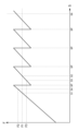
- FIG. 2 is a graph showing an example of positive rotation speed sound data output by a sound data output unit of a saddle-type electric vehicle according to a second embodiment of the present invention.
- FIG. 3 is a graph showing another example of the positive rotation speed sound data output by the sound data output unit of the saddle type electric vehicle according to the second embodiment of the present invention.
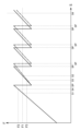
- FIG. 4 is a graph showing an example of positive rotation speed sound data output by a sound data output unit of a saddle-type electric vehicle according to a third embodiment of the present invention.
- FIG. 1 is a diagram illustrating the configuration of a saddle-type electric vehicle according to a first embodiment of the present invention.
- FIG. 2 is a graph showing an example of positive rotation speed sound data output by a sound data output unit of a saddle-type electric vehicle according to a second embodiment of the present invention.
- FIG. 3 is a graph showing another example of the positive
- FIG. 5 is a graph showing an example of positive rotation speed sound data output by a sound data output unit of a saddle-type electric vehicle according to a third embodiment of the present invention.
- FIG. 6 is a schematic diagram of a saddle-type electric vehicle according to a fourth embodiment of the present invention.
- the saddle-type electric vehicle 1 includes an electric motor 2, a driving wheel 3, a saddle-type seat 4 on which a rider R sits in a saddled state, and a sound data output unit 5.
- the driving wheel 3 is driven by the electric motor 2 via a continuously variable transmission (not shown) or a two-speed transmission (not shown), or without a transmission.
- the driving wheel 3 is a rear wheel in FIG. 1, the driving wheel 3 may be a front wheel.
- At least a portion of the saddle-type seat 4 is disposed above the electric motor 2 or the driving wheel 3 in the vehicle up-down direction.
- the positional relationship between the saddle-type seat 4, the electric motor 2, and the driving wheel 3 is not limited to the positional relationship shown in FIG. 1.
- U indicates the vehicle up-down direction
- D indicates the vehicle down-down direction.
- the sound data output unit 5 is configured to acquire information on the rotation speed S, which is the rotation speed of the electric motor 2 or the rotation speed of the drive wheels 3.
- the sound data output unit 5 is configured to generate and output rotation speed sound data DA including data on the main frequency F of the sound corresponding to the rotation speed S of the electric motor 2 or the drive wheels 3, as sound data that is the source of the sound signal sent to the sound generating device 100 configured to generate sound to be heard by the rider R seated on the saddle-type seat 4.
- FIG. 1 an example of the sound generating device 100 installed on the saddle-type electric vehicle 1 is shown by a dashed line, and an example of the sound generating device 100 not installed on the saddle-type electric vehicle 1 is shown by a two-dot chain line.
- FIG. 1 includes a graph showing an example of the relationship between the main frequency F of the sound in the rotation speed sound data DA and the rotation speed S of the electric motor 2 or the drive wheels 3.
- the region of the rotation speed S which is the horizontal axis of the graph in FIG. 1, may be the entire region of the rotation speed S of the electric motor 2 or the drive wheels 3 when the drive wheels 3 are driven by the electric motor 2 via a continuously variable transmission or two-speed transmission, or without a transmission, or may be a part of the entire region.
- the main frequency F of the sound in the rotational speed sound data DA corresponding to the first rotational speed S1 of the electric motor 2 or the drive wheels 3 arranged below at least a portion of the saddle-type seat 4 in the vehicle vertical direction is defined as the first frequency F1.
- the sound data output unit 5 is configured to output rotational speed sound data DA in which the first frequency F1 is the main frequency F of the sound at a second rotational speed S2 that is higher than the first rotational speed S1, and to output rotational speed sound data DA in which the main frequency F of the sound is a frequency different from the first frequency F1 at a third rotational speed S3 that is higher than the first rotational speed S1 and lower than the second rotational speed S2.
- the sound data output unit 5 outputs the rotation speed sound data DA having the first frequency F1 as the main frequency F of the sound
- the sound data output unit 5 outputs the rotation speed sound data DA having a frequency different from the first frequency F1 as the main frequency F of the sound.
- the graph in FIG. 1 shows the third rotation speed S3a and the third rotation speed S3b as two examples of the third rotation speed S3, the third rotation speed S3 in the rotation speed sound data DA in FIG. 1 is not limited to these.
- a saddle-type electric vehicle 1 having a drive wheel 3 driven by an electric motor 2 via a continuously variable transmission or a two-speed transmission or without a transmission it is possible to provide the rider R with sound information that is more easily recognized.
- the rate of change of the main frequency F of the sound with respect to the change in the rotation speed S of the electric motor 2 or the drive wheel 3 can be made larger.
- the rider R compared to a case where the main frequency F of the sound is always increased with an increase in the rotation speed S of the electric motor 2 or the drive wheel 3, it is easier for the rider R to create a running rhythm for the saddle-type electric vehicle 1.
- the rider R grasp the state of the saddle-type electric vehicle 1, such as the vehicle speed, from the sound generated by the sound generating device 100 according to the rotation speed sound data DA.
- FIG. 2 is a graph showing an example of the relationship between the main frequency F of the sound in the rotation speed sound data DA and the rotation speed S of the electric motor 2 or the drive wheels 3 in the second embodiment.
- Fig. 3 is a graph showing another example of the relationship between the main frequency F of the sound in the rotation speed sound data DA and the rotation speed S of the electric motor 2 or the drive wheels 3 in the second embodiment.
- the region of the rotation speed S which is the horizontal axis of the graphs in Figs.
- the sound data output unit 5 of the second embodiment is configured to output rotation speed sound data DA having a second frequency F2 higher than the first frequency F1 as the main frequency F of the sound at a fourth rotation speed S4 that is higher than the first rotation speed S1 and lower than the second rotation speed S2, and to output rotation speed sound data DA having a third frequency F3 lower than the first frequency F1 as the main frequency F of the sound at a fifth rotation speed S5 that is higher than the fourth rotation speed S4 and lower than the second rotation speed S2.
- Both the fourth rotation speed S4 and the fifth rotation speed S5 correspond to the third rotation speed S3 in the first embodiment.
- the rotation speed S at which the rate of change of the main frequency F of the sound in the rotation speed sound data DA with respect to the change in the rotation speed S of the electric motor 2 or the drive wheel 3 changes from positive to negative is defined as the change point SP.
- the sound data output unit 5 of the second embodiment may be configured to generate and output rotational speed sound data DA such that the rotational speed S of the electric motor 2 or the drive wheels 3 passes through multiple change points SP as it increases from the first rotational speed S1 to a sixth rotational speed S6 that is higher than the second rotational speed S2.
- the rotational speed of the electric motor 2 and the rotational speed of the drive wheels 3 may correspond one-to-one. Note that, although there are four change points SP between the first rotational speed S1 and the sixth rotational speed S6 in FIG. 3, the number of change points SP is not limited to this.
- the change in the main frequency F of the sound in the rotational speed sound data DA in response to a change in the rotational speed S of the electric motor 2 or the drive wheels 3 is not limited to that shown in Figures 2 and 3.
- the rotational speed at which the rate of change of the main frequency F of the sound in the rotational speed sound data DA in response to an increase in the rotational speed S of the electric motor 2 or the drive wheels 3 changes from positive to negative is the same as the rotational speed at which the rate of change of the main frequency F of the sound in the rotational speed sound data DA in response to a decrease in the rotational speed S of the electric motor 2 or the drive wheels 3 changes from positive to negative, but may be different.
- the change in frequency of the sound generated in response to changes in vehicle speed is similar to the change in frequency of the sound obtained from a saddle-type vehicle having an engine and a multi-speed transmission in response to changes in vehicle speed.
- the main frequency F of the sound in the rotational speed sound data DA is changed in this way, it is easier for the rider R to create a driving rhythm for the saddle-type electric vehicle 1.
- the rider R grasps the state of the saddle-type electric vehicle 1, such as the vehicle speed, from the sound generated by the sound generating device 100 in response to the rotational speed sound data DA.
- FIG. 4 is a graph showing an example of the relationship between the main frequency F of the sound in the rotation speed sound data DA and the rotation speed S of the electric motor 2 or the drive wheels 3 in the third embodiment.
- Fig. 5 is a graph showing another example of the relationship between the main frequency F of the sound in the rotation speed sound data DA and the rotation speed S of the electric motor 2 or the drive wheels 3 in the third embodiment. The region of the rotation speed S on the horizontal axis of the graphs in Figs.
- 4 and 5 may be the entire region of the rotation speed S of the electric motor 2 or the drive wheels 3 when the drive wheels 3 are driven by the electric motor 2 via a continuously variable transmission or a two-speed transmission or without a transmission, or may be a part of the entire region.
- the sound data output unit 5 of the third embodiment is configured to be able to change the change point SP.
- the definition of the change point SP is as described in the second embodiment.
- the relationship between the main frequency F and the rotation speed S in the rotation speed sound data DA before the change point SP is changed is shown by a solid line
- the relationship between the main frequency F and the rotation speed S in the rotation speed sound data DA when the change point SP is increased is shown by a two-dot chain line.
- the change amount of the change point SP is small, but the change amount of the change point SP may be large.
- all of the multiple change points SP are changed, but only some of the multiple change points SP may be changed.
- the change amount of the multiple change points SP is almost the same, but the change amount of the multiple change points SP may be different.
- the change in the main frequency F of the sound in the rotation speed sound data DA with respect to the change in the rotation speed S of the electric motor 2 or the drive wheels 3 is not limited to that shown in FIG. 4 and FIG. 5.
- the rotation speed at which the rate of change of the main frequency F of the sound in the rotation speed sound data DA changes from positive to negative in response to an increase in the rotation speed S of the electric motor 2 or the drive wheels 3 is the same as the rotation speed at which the rate of change of the main frequency F of the sound in the rotation speed sound data DA changes from positive to negative in response to a decrease in the rotation speed S of the electric motor 2 or the drive wheels 3, but may be different.
- the change point SP may be changed, for example, in response to differences in the environment, such as the route on which the saddle riding type electric vehicle 1 travels. More specifically, for example, the change point SP may be changed in response to the shape of the route. Also, the change point SP may be changed, for example, in response to differences in the rider R riding the saddle riding type electric vehicle 1. More specifically, for example, the change point SP may be changed in response to the driving technique of the rider R. Also, the change point SP may be changed in response to differences in the saddle riding type electric vehicle 1. The change point SP may be changed by combining these examples. Also, for example, in a race to compete for the longest driving time, the change point SP may be adjusted to shorten the driving time. If the change point SP is slightly increased, it may be possible to slightly slow down the vehicle speed that the rider R feels from the sound generated by the sound generating device 100. As a result, it may be possible to shorten the driving time.
- the fourth embodiment has the configuration of the first embodiment.
- the fourth embodiment may have the configuration of the second or third embodiment.
- the sound data output unit 5 according to the fourth embodiment is configured to generate and output notification sound data DB different from the rotation speed sound data DA including data on the main frequency F of the sound according to the rotation speed S of the electric motor 2 or the driving wheel 3 as sound data that is the source of the sound signal sent to the sound generating device 100.
- the sound generated by the sound generating device 100 according to the notification sound data DB can notify the rider R of various information depending on the timing and type of the sound. Therefore, according to the saddle-type electric vehicle 1 according to the present embodiment, sound information that is more easily recognized and can notify the rider R of more information can be provided to the rider R.
- the sound data output unit 5 may be configured to output the alarm sound data DB when outputting the rotation speed sound data DA.
- the sound generating device 100 may generate sound based on both a sound signal C based on the rotation speed sound data DA and a sound signal C based on the alarm sound data DB. As shown in FIG. 6(b), the sound generating device 100 may generate sound based on a sound signal C based on both the rotation speed sound data DA and the alarm sound data DB.
- the sound data output unit 5 may be configured to output the alarm sound data DB when the rotation speed sound data DA is not being output.
- the sound data output unit 5 may be configured to output the alarm sound data DB both when the rotation speed sound data DA is not being output and when the rotation speed sound data DA is not being output.
- the notification sound data DB may be data for generating a sound to notify the rider R of at least one of the state of the saddle riding type electric vehicle 1 and the state around the saddle riding type electric vehicle 1. Specific examples of the notification sound data DB are described below. However, the notification sound data DB of this embodiment is not limited to these.
- the saddle-type electric vehicle 1 may be equipped with a position information acquisition device (not shown) that acquires position information of the saddle-type electric vehicle 1.
- the sound data output unit 5 may generate and output notification sound data DB according to the position information of the saddle-type electric vehicle 1 acquired by the position information acquisition device.
- the notification sound data DB may be output to notify the rider R that the saddle-type electric vehicle 1 has reached a predetermined position. More specifically, for example, the notification sound data DB may be output when the distance to a corner ahead in the path has reached a predetermined distance. This makes it possible to inform the rider R of the timing to start decelerating, for example.
- the sound data output unit 5 may generate and output the notification sound data DB according to the position information of the saddle-type electric vehicle 1 acquired by the position information acquisition device and the rotation speed S of the electric motor 2 or the drive wheels 3.
- the notification sound data DB may be output to notify the rider R that the rotation speed S of the electric motor 2 or the drive wheels 3 when the saddle-type electric vehicle 1 reaches a predetermined position is lower or higher than a predetermined speed. More specifically, for example, the notification sound data DB may be output when the vehicle speed when the distance to a corner ahead in the path reaches a predetermined distance is higher than the predetermined speed.
- the notification sound data DB may be output when the vehicle speed when the predetermined position is reached is lower than the predetermined speed. This makes it possible to urge the rider R to accelerate at a timing appropriate for acceleration, for example.
- the sound data output unit 5 may generate and output the alarm sound data DB according to the rotation speed S of the electric motor 2 or the drive wheels 3.
- the alarm sound data DB may be output to notify the rider R that the rotation speed S of the electric motor 2 or the drive wheels 3 has reached a predetermined speed. More specifically, for example, the alarm sound data DB may be output when the vehicle speed is higher than a predetermined speed. This can, for example, prompt the rider R to decelerate. Also, for example, the alarm sound data DB may be output when the vehicle speed is lower than a predetermined speed. This can, for example, prompt the rider R to accelerate.
- 1 saddle-type electric vehicle
- 2 electric motor
- 3 drive wheel
- 4 saddle-type seat
- 5 sound data output unit
- 100 sound generating device
- DA rotational speed sound data
- DB notification sound data
- F main frequency
- F1 first frequency
- F2 second frequency
- F3 third frequency
- R rider
- S rotational speed of electric motor or drive wheel
- S1 first rotational speed
- S2 second rotational speed
- S3, S3a, S3b third rotational speed
- S4 fourth rotational speed
- S5 fifth rotational speed
- SP change point
Landscapes
- Engineering & Computer Science (AREA)
- Mechanical Engineering (AREA)
- Chemical & Material Sciences (AREA)
- Combustion & Propulsion (AREA)
- Transportation (AREA)
- Physics & Mathematics (AREA)
- Acoustics & Sound (AREA)
- Electric Propulsion And Braking For Vehicles (AREA)
Abstract
L'invention concerne un véhicule électrique à selle (1) comprenant une unité de sortie de données sonores (5) qui génère et délivre, en tant que données sonores formant la source d'un signal sonore à envoyer à un dispositif de génération de son (100), des données sonores de vitesse de rotation (DA) contenant des données relatives à la fréquence principale (F) de son correspondant à la vitesse de rotation (S) d'un moteur électrique (2) ou d'une roue motrice (3). Si la fréquence principale du son dans les données sonores de vitesse de rotation correspondant à une première vitesse de rotation (S1) du moteur électrique ou de la roue motrice, agencé vers le bas le long de la direction haut/bas du véhicule d'au moins une partie d'un siège de style selle (4) sur lequel un conducteur (R) s'assoit, est définie comme une première fréquence (F1), alors l'unité de sortie de données sonores délivre des données sonores de vitesse de rotation avec la première fréquence qui est la fréquence principale du son à une deuxième vitesse de rotation (S2), supérieure à la première vitesse de rotation, et délivre des données sonores de vitesse de rotation avec une fréquence différente de la première fréquence qui est la fréquence principale du son à une troisième vitesse de rotation (S3) supérieure à la première vitesse de rotation et inférieure à la deuxième vitesse de rotation.
Priority Applications (5)
| Application Number | Priority Date | Filing Date | Title |
|---|---|---|---|
| PCT/JP2023/012793 WO2024201775A1 (fr) | 2023-03-29 | 2023-03-29 | Véhicule électrique à selle |
| TW113105767A TWI886799B (zh) | 2023-03-29 | 2024-02-19 | 跨坐型電動車輛 |
| DE102024202660.3A DE102024202660A1 (de) | 2023-03-29 | 2024-03-20 | Spreizsitz-elektrofahrzeug |
| FR2402885A FR3147239A1 (fr) | 2023-03-29 | 2024-03-22 | Véhicule électrique à selle |
| JP2024056782A JP7678182B2 (ja) | 2023-03-29 | 2024-03-29 | 鞍乗型電動車両 |
Applications Claiming Priority (1)
| Application Number | Priority Date | Filing Date | Title |
|---|---|---|---|
| PCT/JP2023/012793 WO2024201775A1 (fr) | 2023-03-29 | 2023-03-29 | Véhicule électrique à selle |
Publications (1)
| Publication Number | Publication Date |
|---|---|
| WO2024201775A1 true WO2024201775A1 (fr) | 2024-10-03 |
Family
ID=92712890
Family Applications (1)
| Application Number | Title | Priority Date | Filing Date |
|---|---|---|---|
| PCT/JP2023/012793 Ceased WO2024201775A1 (fr) | 2023-03-29 | 2023-03-29 | Véhicule électrique à selle |
Country Status (5)
| Country | Link |
|---|---|
| JP (1) | JP7678182B2 (fr) |
| DE (1) | DE102024202660A1 (fr) |
| FR (1) | FR3147239A1 (fr) |
| TW (1) | TWI886799B (fr) |
| WO (1) | WO2024201775A1 (fr) |
Citations (4)
| Publication number | Priority date | Publication date | Assignee | Title |
|---|---|---|---|---|
| JP2000001142A (ja) * | 1998-06-17 | 2000-01-07 | Yamaha Motor Co Ltd | 車両用エンジン模擬音発生装置 |
| JP2017062320A (ja) * | 2015-09-24 | 2017-03-30 | ヤマハ発動機株式会社 | 電動車両 |
| WO2017056541A1 (fr) * | 2015-09-28 | 2017-04-06 | ヤマハ発動機株式会社 | Véhicule électrique |
| WO2021246009A1 (fr) * | 2020-06-02 | 2021-12-09 | 本田技研工業株式会社 | Véhicule électrique |
Family Cites Families (8)
| Publication number | Priority date | Publication date | Assignee | Title |
|---|---|---|---|---|
| JP4726586B2 (ja) * | 2005-09-20 | 2011-07-20 | 鈴木 旭 | 自動車用ドライブレコーダ |
| WO2011148470A1 (fr) * | 2010-05-26 | 2011-12-01 | 三菱電機株式会社 | Dispositif de commande de son simulé et corps mobile à traction électrique équipé de celui-ci |
| JP2011246121A (ja) | 2010-05-26 | 2011-12-08 | Mitsubishi Electric Corp | 擬似音制御装置、擬似音発生装置、およびそれを備えた電動移動体 |
| JP5785739B2 (ja) | 2011-02-28 | 2015-09-30 | 本田技研工業株式会社 | 鞍乗り型電動車両の車両接近告知装置 |
| JP2018023223A (ja) * | 2016-08-03 | 2018-02-08 | ヤマハ発動機株式会社 | 電動車両 |
| WO2021014600A1 (fr) * | 2019-07-24 | 2021-01-28 | ヤマハ発動機株式会社 | Véhicule à enfourcher |
| JP7454119B2 (ja) | 2019-08-21 | 2024-03-22 | マツダ株式会社 | 車両用音生成装置 |
| KR20230012107A (ko) * | 2021-07-14 | 2023-01-26 | 현대자동차주식회사 | 전기자동차의 가상 사운드 제공 장치 및 방법 |
-
2023
- 2023-03-29 WO PCT/JP2023/012793 patent/WO2024201775A1/fr not_active Ceased
-
2024
- 2024-02-19 TW TW113105767A patent/TWI886799B/zh active
- 2024-03-20 DE DE102024202660.3A patent/DE102024202660A1/de active Pending
- 2024-03-22 FR FR2402885A patent/FR3147239A1/fr active Pending
- 2024-03-29 JP JP2024056782A patent/JP7678182B2/ja active Active
Patent Citations (4)
| Publication number | Priority date | Publication date | Assignee | Title |
|---|---|---|---|---|
| JP2000001142A (ja) * | 1998-06-17 | 2000-01-07 | Yamaha Motor Co Ltd | 車両用エンジン模擬音発生装置 |
| JP2017062320A (ja) * | 2015-09-24 | 2017-03-30 | ヤマハ発動機株式会社 | 電動車両 |
| WO2017056541A1 (fr) * | 2015-09-28 | 2017-04-06 | ヤマハ発動機株式会社 | Véhicule électrique |
| WO2021246009A1 (fr) * | 2020-06-02 | 2021-12-09 | 本田技研工業株式会社 | Véhicule électrique |
Also Published As
| Publication number | Publication date |
|---|---|
| JP2025023876A (ja) | 2025-02-18 |
| FR3147239A1 (fr) | 2024-10-04 |
| DE102024202660A1 (de) | 2024-10-02 |
| TW202438344A (zh) | 2024-10-01 |
| TWI886799B (zh) | 2025-06-11 |
| JP7678182B2 (ja) | 2025-05-15 |
Similar Documents
| Publication | Publication Date | Title |
|---|---|---|
| US11124266B2 (en) | Human-powered vehicle control device | |
| TWI666143B (zh) | 電動輔助系統及電動輔助車輛 | |
| CN103260951B (zh) | 行驶联动声产生装置 | |
| JP7254851B2 (ja) | 人力駆動車両の制御装置 | |
| JP6604148B2 (ja) | 前後輪駆動車両の駆動制御システムおよびその駆動制御方法 | |
| JP7736422B2 (ja) | 人力駆動車用の報知装置、人力駆動車用の報知システム、および、人力駆動車用の制御装置 | |
| JP2018196166A (ja) | 電動車両 | |
| JP6994435B2 (ja) | 制御装置および検出システム | |
| JP2024085013A (ja) | 車両制御装置及び車両制御方法 | |
| JP2020104743A (ja) | 制御装置および変速システム | |
| JP7678182B2 (ja) | 鞍乗型電動車両 | |
| US12291303B2 (en) | Suspension control device | |
| US11358678B2 (en) | Control system for human-powered vehicle | |
| US20250256804A1 (en) | Detection system, detection method, and computer-readable storage medium | |
| JP7643989B2 (ja) | 制御システム、および、人力駆動車用制御装置 | |
| JP7621525B2 (ja) | 鞍乗り型車両及び触覚刺激システム | |
| JP7566623B2 (ja) | 人力駆動車の制御装置 | |
| JP7498572B2 (ja) | 制御装置及び制御方法 | |
| US11479253B1 (en) | Motorized vehicle incorporating exercise apparatus | |
| JP7683049B2 (ja) | 鞍乗り型車両及び触覚刺激システム | |
| JP2020080591A (ja) | 電動車両 | |
| JP7848049B2 (ja) | 制御装置 | |
| JP7847475B2 (ja) | 制御装置 | |
| JP7484702B2 (ja) | モータ制御装置 | |
| JP2025075749A (ja) | 人力駆動車用の制御装置 |
Legal Events
| Date | Code | Title | Description |
|---|---|---|---|
| 121 | Ep: the epo has been informed by wipo that ep was designated in this application |
Ref document number: 23930415 Country of ref document: EP Kind code of ref document: A1 |
|
| NENP | Non-entry into the national phase |
Ref country code: DE |
|
| 122 | Ep: pct application non-entry in european phase |
Ref document number: 23930415 Country of ref document: EP Kind code of ref document: A1 |