WO2024201963A1 - Turbocompresseur à déplacement variable et procédé d'assemblage pour turbocompresseur à déplacement variable - Google Patents
Turbocompresseur à déplacement variable et procédé d'assemblage pour turbocompresseur à déplacement variable Download PDFInfo
- Publication number
- WO2024201963A1 WO2024201963A1 PCT/JP2023/013418 JP2023013418W WO2024201963A1 WO 2024201963 A1 WO2024201963 A1 WO 2024201963A1 JP 2023013418 W JP2023013418 W JP 2023013418W WO 2024201963 A1 WO2024201963 A1 WO 2024201963A1
- Authority
- WO
- WIPO (PCT)
- Prior art keywords
- housing
- driving force
- control arm
- nozzle device
- variable
- Prior art date
- Legal status (The legal status is an assumption and is not a legal conclusion. Google has not performed a legal analysis and makes no representation as to the accuracy of the status listed.)
- Ceased
Links
Images


Classifications
-
- F—MECHANICAL ENGINEERING; LIGHTING; HEATING; WEAPONS; BLASTING
- F01—MACHINES OR ENGINES IN GENERAL; ENGINE PLANTS IN GENERAL; STEAM ENGINES
- F01D—NON-POSITIVE DISPLACEMENT MACHINES OR ENGINES, e.g. STEAM TURBINES
- F01D17/00—Regulating or controlling by varying flow
- F01D17/10—Final actuators
- F01D17/12—Final actuators arranged in stator parts
- F01D17/14—Final actuators arranged in stator parts varying effective cross-sectional area of nozzles or guide conduits
- F01D17/16—Final actuators arranged in stator parts varying effective cross-sectional area of nozzles or guide conduits by means of nozzle vanes
- F01D17/165—Final actuators arranged in stator parts varying effective cross-sectional area of nozzles or guide conduits by means of nozzle vanes for radial flow, i.e. the vanes turning around axes which are essentially parallel to the rotor centre line
-
- F—MECHANICAL ENGINEERING; LIGHTING; HEATING; WEAPONS; BLASTING
- F05—INDEXING SCHEMES RELATING TO ENGINES OR PUMPS IN VARIOUS SUBCLASSES OF CLASSES F01-F04
- F05D—INDEXING SCHEME FOR ASPECTS RELATING TO NON-POSITIVE-DISPLACEMENT MACHINES OR ENGINES, GAS-TURBINES OR JET-PROPULSION PLANTS
- F05D2220/00—Application
- F05D2220/40—Application in turbochargers
-
- F—MECHANICAL ENGINEERING; LIGHTING; HEATING; WEAPONS; BLASTING
- F05—INDEXING SCHEMES RELATING TO ENGINES OR PUMPS IN VARIOUS SUBCLASSES OF CLASSES F01-F04
- F05D—INDEXING SCHEME FOR ASPECTS RELATING TO NON-POSITIVE-DISPLACEMENT MACHINES OR ENGINES, GAS-TURBINES OR JET-PROPULSION PLANTS
- F05D2260/00—Function
- F05D2260/50—Kinematic linkage, i.e. transmission of position
- F05D2260/56—Kinematic linkage, i.e. transmission of position using cams or eccentrics
-
- Y—GENERAL TAGGING OF NEW TECHNOLOGICAL DEVELOPMENTS; GENERAL TAGGING OF CROSS-SECTIONAL TECHNOLOGIES SPANNING OVER SEVERAL SECTIONS OF THE IPC; TECHNICAL SUBJECTS COVERED BY FORMER USPC CROSS-REFERENCE ART COLLECTIONS [XRACs] AND DIGESTS
- Y02—TECHNOLOGIES OR APPLICATIONS FOR MITIGATION OR ADAPTATION AGAINST CLIMATE CHANGE
- Y02T—CLIMATE CHANGE MITIGATION TECHNOLOGIES RELATED TO TRANSPORTATION
- Y02T10/00—Road transport of goods or passengers
- Y02T10/10—Internal combustion engine [ICE] based vehicles
- Y02T10/12—Improving ICE efficiencies
Definitions
- This disclosure relates to a variable geometry turbocharger and a method for assembling a variable geometry turbocharger.
- a known turbocharger that uses the energy of exhaust gas from an internal combustion engine to supercharge the intake air of the internal combustion engine is equipped with a variable capacity turbine including a variable nozzle device that changes the blade angle of the nozzle vanes (see, for example, Patent Document 1).
- a variable capacity turbine has multiple nozzle vanes arranged in a line around the circumferential direction of the turbine wheel in an exhaust gas flow path that sends exhaust gas from the scroll flow path of the turbine to the turbine wheel, and the blade angle of these nozzle vanes can be changed from the outside by an actuator to adjust the flow path cross-sectional area of the exhaust gas flow path (the flow path between adjacent nozzle vanes).
- a variable capacity turbine adjusts the flow path cross-sectional area of the exhaust gas flow path to change the flow speed and pressure of the exhaust gas led to the turbine wheel, thereby enhancing the supercharging effect.
- the rotating shaft that penetrates the inside and outside of the housing and the engagement plate that transmits driving force to the variable nozzle device inside the housing may be fixed by welding.
- At least one embodiment of the present disclosure aims to provide a variable geometry turbocharger and a method for assembling a variable geometry turbocharger that can suppress a reduction in the operating range of the variable nozzle device.
- a variable geometry turbocharger includes: A turbine wheel; a first housing having a scroll flow passage; a variable nozzle device configured to form a gas flow passage from the scroll flow passage toward the turbine wheel and to adjust the flow of gas through the gas flow passage; a second housing connected to the first housing and defining an accommodation space between the first housing and the second housing for accommodating the turbine wheel and the variable nozzle device, the second housing having a through hole communicating the accommodation space with an outside of the second housing; a driving force transmission device configured to transmit a driving force from an actuator disposed outside the second housing to the variable nozzle device,
- the driving force transmission device includes: a control arm having an engagement portion that engages with a driving force input portion of the variable nozzle device in the accommodation space and a rotation shaft portion that passes through the through hole and partially protrudes outside the second housing; a control lever disposed outside the second housing and having a fixed portion that is fixed to the rotation shaft portion of the control arm by joining.
- a method for assembling a variable geometry turbocharger includes: A turbine wheel; a first housing having a scroll flow passage; a variable nozzle device configured to form a gas flow passage from the scroll flow passage toward the turbine wheel and to adjust the flow of gas through the gas flow passage; a second housing connected to the first housing and defining an accommodation space between the first housing and the second housing for accommodating the turbine wheel and the variable nozzle device, the second housing having a through hole communicating the accommodation space with an outside of the second housing; a driving force transmission device configured to transmit a driving force from an actuator disposed outside the second housing to the variable nozzle device,
- the driving force transmission device includes: a control arm having an engagement portion that engages with a driving force input portion of the variable nozzle device in the accommodation space and a rotation shaft portion that passes through the through hole and partially protrudes outside the second housing; a control lever that is disposed outside the second housing and has a fixed portion that is fixed to the rotation shaft portion of the control arm by joining, The method for assembling the driving force transmission device
- At least one embodiment of the present disclosure provides a variable geometry turbocharger and a method for assembling a variable geometry turbocharger that can suppress a reduction in the operating range of a variable nozzle device.
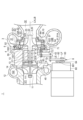
- FIG. 1 is a schematic cross-sectional view taken along an axis of a variable geometry turbocharger according to an embodiment of the present disclosure.
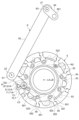
- FIG. 1 is a schematic diagram of a variable nozzle device and a driving force transmission device of a variable geometry turbocharger according to an embodiment of the present disclosure, viewed from one axial side.
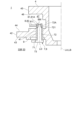
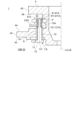
- FIG. 1 is a schematic cross-sectional view taken along an axis in the vicinity of a driving force transmission device of a variable geometry turbocharger according to an embodiment of the present disclosure.
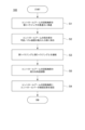
- FIG. FIG. 2 is a flow diagram illustrating an example of a method for assembling a variable geometry turbocharger according to an embodiment of the present disclosure.
- FIG. 11 is a schematic cross-sectional view taken along an axis near a driving force transmission device of a variable geometry turbocharger according to a comparative example.
- 1 is a schematic cross-sectional view taken along an axis in the vicinity of a driving force transmission device of a variable geometry turbocharger according to an embodiment of the present disclosure.
- FIG. 1 is a schematic cross-sectional view taken along an axis in the vicinity of a driving force transmission device of a variable geometry turbocharger according to an embodiment of the present disclosure.
- Fig. 1 is a schematic cross-sectional view along an axis line LA of a variable geometry turbocharger 1 according to an embodiment of the present disclosure.
- the variable geometry turbocharger 1 according to the present disclosure is applicable to, for example, turbochargers (superchargers) for automobiles, marine use, or industrial use (for example, land-based power generation).
- the turbocharger 1 according to some embodiments includes at least a turbine rotor 20, a first housing (turbine housing) 3, a second housing (bearing housing) 4, a variable nozzle device 5, and a driving force transmission device 6.
- the turbocharger 1 further includes a centrifugal impeller 11, a third housing (compressor housing) 12, and a bearing 13.
- the turbine rotor 20 includes a turbine shaft 21 extending along an axis LA of the turbine rotor 20, and a turbine wheel 2 provided on one side (the right side in the figure) of the turbine shaft 21.
- the impeller 11 is attached to the other side (the left side in the figure) of the turbine shaft 21.
- the bearing 13 is accommodated in the second housing 4 between the impeller 11 and the turbine wheel 2 and configured to rotatably support the turbine shaft 21.
- the second housing 4 has a bearing support portion 14 that supports the bearing 13 from the outside in the radial direction.
- the second housing 4 of the turbocharger 1 with the turbine rotor 20, the impeller 11, and the bearing 13 attached thereto is defined as a cartridge.
- the direction in which the axis LA of the turbine rotor 20 extends is referred to as the axial direction of the turbine rotor 20, the direction perpendicular to the axis LA is referred to as the radial direction of the turbine rotor 20, and the circumferential direction around the axis LA is referred to as the circumferential direction of the turbine rotor 20.
- the axial direction, radial direction, and circumferential direction of the turbine rotor 20 may be simply referred to as the axial direction, radial direction, and circumferential direction, respectively.
- the side where the turbine wheel 2 is located relative to the impeller 11 the right side in FIG.
- the turbine wheel 2 includes a hub 22 having a substantially truncated cone shape and a plurality of turbine blades 23 provided on the outer circumferential surface of the hub 22.
- the plurality of turbine blades 23 are arranged at intervals from one another in the circumferential direction about the axis line LA.
- the turbine wheel 2 is provided so as to be rotatable integrally with a turbine shaft 21 about the axis line LA.
- the turbine wheel 2 is configured to guide exhaust gas introduced from the outside in the radial direction of the turbine wheel 2 to the above-mentioned front side along the axial direction of the turbine wheel 2.
- the turbine wheel 2 is an open-type impeller that does not include an annular member surrounding the outer periphery of the plurality of turbine blades 23.
- the impeller 11 includes a hub 111 having a substantially truncated cone shape and a plurality of compressor vanes 112 provided on the outer circumferential surface of the hub 111.
- the plurality of compressor vanes 112 are arranged at intervals from each other in the circumferential direction around the axis line LA.
- the impeller 11 is attached to the turbine shaft 21 so as to be rotatable integrally with the turbine shaft 21 about the axis line LA.
- the impeller 11 is configured to guide a combustion gas (e.g., air), which is a gas used as an oxidizer for combustion in an internal combustion engine (engine) (not shown) and is introduced from the rear side along the axial direction of the impeller 11, to the outside in the radial direction of the impeller 11.
- a combustion gas e.g., air
- the impeller 11 is an open-type impeller that does not include an annular member surrounding the outer periphery of the plurality of compressor vanes 112.
- the first housing 3 is connected to the second housing 4 and configured to rotatably house the turbine wheel 2 between the first housing 3 and the second housing 4.
- the third housing 12 is connected to the second housing 4 and configured to rotatably house the impeller 11 between the second housing 4.
- the second housing 4 is disposed between the first housing 3 and the third housing 12 and is connected to each of the first housing 3 and the third housing 12 via fastening members (not shown) such as bolts.
- the first housing 3 is formed with a scroll passage 31 for guiding exhaust gas discharged from the internal combustion engine to the turbine wheel 2, and an exhaust gas exhaust passage 32 for discharging exhaust gas that has passed through the turbine wheel 2 to the outside of the first housing 3 (turbocharger 1).
- the first housing 3 has the scroll passage 31 and the exhaust gas exhaust passage 32.
- the scroll passage 31 is provided on the radial outside of the turbine wheel 2 so as to surround the periphery of the turbine wheel 2, and is composed of a spiral passage extending along the circumferential direction.
- the exhaust gas exhaust passage 32 extends toward the front side along the axial direction.
- the variable nozzle device 5 is configured to form a gas flow passage 33A from the scroll flow passage 31 toward the turbine wheel 2, and to adjust the flow of gas flowing through the gas flow passage 33A.
- the gas flow passage 33A is provided between the scroll flow passage 31 and the turbine wheel 2 in the radial direction of the turbine wheel 2 so as to surround the radial outside of the turbine wheel 2.
- the gas flow passage 33A is part of the accommodation space 33, and is formed on the outer periphery side of the accommodation portion that accommodates the turbine wheel 2 in the accommodation space 33. Exhaust gas is guided from the scroll flow passage 31 to the turbine wheel 2 via the gas flow passage 33A.
- the exhaust gas generated by combustion in the internal combustion engine and discharged from the internal combustion engine is guided to the turbine wheel 2 via the scroll passage 31 and the gas passage 33A.
- the turbocharger 1 is configured to rotate the turbine wheel 2 using the energy of the exhaust gas guided to the turbine wheel 2.
- the impeller 11 is coaxially connected to the turbine wheel 2 via the turbine shaft 21, and is therefore driven to rotate about the axis LA in conjunction with the rotation of the turbine wheel 2.
- the exhaust gas that has driven the turbine wheel 2 to rotate is discharged to the outside of the first housing 3 via the exhaust gas discharge passage 32.
- the turbocharger 1 is configured to rotate the impeller 11 around the axis LA, thereby drawing in air (combustion gas) into the third housing 12, compressing the air, and sending the compressed air to the internal combustion engine.
- the third housing 12 is formed with a gas introduction passage 121 and a scroll passage 122.
- the gas introduction passage 121 is a passage for taking in air (combustion gas) from outside the third housing 12 and guiding the taken-in air to the impeller 11.
- the gas introduction passage 121 extends along the axial direction of the impeller 11 and is provided on one side (rear side) of the impeller 11 in the axial direction. By driving the impeller 11 to rotate, air is taken in from outside the third housing 12 into the gas introduction passage 121, and the taken-in air flows through the gas introduction passage 121 toward the impeller 11 and is guided to the impeller 11.
- the scroll passage 122 is provided radially outside the impeller 11 so as to surround the periphery of the impeller 11, and is a spiral passage extending along the circumferential direction of the impeller 11. Air that passes through the impeller 11 and is compressed by the impeller 11 is guided to the scroll passage 122. The compressed air that has passed through the scroll passage 122 is guided to the internal combustion engine.
- variable nozzle device 2 is a schematic diagram of the variable nozzle device 5 and the driving force transmission device 6 of the turbocharger 1 according to one embodiment of the present disclosure, viewed from one side (rear side) in the axial direction.
- the variable nozzle device 5 includes a driving force input portion 51, a nozzle mount 52, a plurality of nozzle vanes 53, a drive ring 54, and a plurality of lever plates 55, as shown in FIGS.
- the nozzle mount 52 forms a gas flow path 33A between itself and the other member 10.
- the nozzle mount 52 is located rearward of the gas flow path 33A, and the other member 10 is located forward of the gas flow path 33A.
- the direction in which the axis LB of the nozzle mount 52 (variable nozzle device 5) extends is referred to as the axial direction of the variable nozzle device 5
- the direction perpendicular to the axis LB is referred to as the radial direction of the variable nozzle device 5
- the circumferential direction around the axis LB is referred to as the circumferential direction of the variable nozzle device 5.
- the extension direction of the axis LB is the direction along the extension direction of the axis LA.
- the nozzle mount 52 is disposed on the outer periphery of the turbine wheel 2 and includes an annular plate extending along the circumferential direction of the variable nozzle device 5.
- the nozzle mount 52 has an annular mount-side flow passage surface 521 that faces the gas flow passage 33A on one side in the thickness direction of the nozzle mount 52, i.e., the front side.
- the nozzle mount 52 has an annular mount-side back surface 522 on the other side in the thickness direction of the nozzle mount 52 (the opposite side to the mount-side flow passage surface 521), i.e., the rear side.
- the variable nozzle device 5 further includes a nozzle plate 56, which is the other member 10 described above, as shown in FIG. 1.
- the nozzle plate 56 includes an annular plate extending along the circumferential direction of the variable nozzle device 5.
- the nozzle plate 56 has an annular plate-side flow path surface 561 facing the gas flow path 33A on one side in the thickness direction of the nozzle plate 56, i.e., the rear side.
- the plate-side flow path surface 561 is disposed opposite the mount-side flow path surface 521 with a gap therebetween, and forms the gas flow path 33A between the plate-side flow path surface 561 and the mount-side flow path surface 521.
- the variable nozzle device 5 may not include the nozzle plate 56, and the first housing 3, which is the other member 10, may have a flow path surface that forms the gas flow path 33A between the mount-side flow path surface 521.
- variable nozzle device 5 further includes a plurality of nozzle supports 57 that support the nozzle mount 52 and the nozzle plate 56 in a state spaced apart from each other.
- Each of the plurality of nozzle supports 57 is disposed outwardly of the plurality of nozzle vanes 53 in the radial direction of the variable nozzle device 5.
- the mount-side rear surface 522 of the nozzle mount 52 forms a rear space 33B between the first housing 3 and the second housing 4.
- the rear space 33B is part of the accommodation space 33, and is formed on the opposite side of the nozzle mount 52 from the gas flow path 33A.
- Each of the plurality of nozzle vanes 53 is disposed in the gas flow passage 33A, and is supported by the nozzle mount 52 so as to be rotatable about its own center of rotation RC.
- the plurality of nozzle vanes 53 are disposed at intervals in the circumferential direction of the variable nozzle device 5.
- the drive ring 54 is disposed in the rear space 33B, and has the driving force input unit 51 attached thereto.
- the drive ring 54 is provided so as to be rotatable about the axis LB relative to the nozzle mount 52 by the driving force transmitted via the driving force input unit 51.
- the drive ring 54 includes an annular body extending along the circumferential direction of the variable nozzle device 5.
- the drive ring 54 has fitted portions 541 at multiple locations along the circumferential direction of the variable nozzle device 5.
- the variable nozzle device 5 includes lever plates 55 in the same number as the nozzle vanes 53.
- Each of the lever plates 55 includes a vane fixing portion 551 fixed to one of the nozzle vanes 53, and a fitting portion 552 fitting to one of the fitted portions 541 of the drive ring 54.
- Each of the lever plates 55 is disposed in the rear space 33B, and the vane fixing portion 551 provided on one side of the lever plate 55 is fixed to the corresponding nozzle vane 53, and the fitting portion 552 provided on the other side of the lever plate 55 is fitted to the corresponding fitted portion 541.
- Each of the lever plates 55 is configured to change the blade angle of the nozzle vane 53 fixed to the vane fixing portion 551 in conjunction with the rotation of the drive ring 54 about the axis LB.
- each of the multiple mating portions 541 includes a groove portion formed on the outer peripheral edge portion of the drive ring 54, and each of the multiple mating portions 552 is accommodated inside the corresponding groove portion and is adapted to be loosely mated with the groove portion.
- the nozzle mount 52 has a plurality of through holes 523 penetrating the mount side flow passage surface 521 and the mount side back surface 522.
- the plurality of through holes 523 are arranged at intervals in the circumferential direction of the variable nozzle device 5.
- the nozzle mount 52 has the same number of through holes 523 as the nozzle vanes 53.
- Each of the plurality of lever plates 55 is inserted through a corresponding through hole 523.
- the variable nozzle device 5 transmits the driving force from the actuator 60 to the multiple nozzle vanes 53 via the drive ring 54 and multiple lever plates 55, causing the multiple nozzle vanes 53 to rotate around their respective rotation centers RC, changing the blade angle of each, thereby adjusting the flow path cross-sectional area of the gas flow path 33A.
- the turbocharger 1 can change the flow speed and pressure (inlet pressure) of the exhaust gas guided to the turbine wheel 2, and the flow speed and pressure (outlet pressure) of the exhaust gas that has passed through the turbine wheel 2, thereby controlling the boost pressure of the turbocharger 1.
- (Drive force transmission device) 3 is a schematic cross-sectional view taken along the axis LA near the driving force transmission device 6 of the turbocharger 1 according to one embodiment of the present disclosure. As shown in FIG. 1, the driving force transmission device 6 is configured to transmit driving force from an actuator 60 disposed outside the second housing 4 to the variable nozzle device 5.
- the driving force transmission device 6 includes at least a control arm 7 and a control lever 8.
- FIG. 1 it includes a second housing side connecting part 42 that extends from the front end of the second housing 4 toward the outside in the radial direction along the radial direction and is connected to the first housing 3, and a third housing side connecting part 45 that extends from the rear end of the second housing 4 toward the outside in the radial direction along the radial direction and is connected to the third housing 12.
- the second housing side connecting portion 42 has a surface 43 facing the rear space 33B on one side in the thickness direction of the second housing side connecting portion 42, i.e., the front side, and has a second surface 44 facing the outer space 47 of the second housing 4 on the other side in the thickness direction of the second housing side connecting portion 42, i.e., the rear side.
- the third housing side connecting portion 45 has a surface 46 facing the outer space 47 of the second housing 4 on one side in the thickness direction of the third housing side connecting portion 45, i.e., the front side.
- the first surface 46 faces the second surface 44 across the outer space 47.
- the through hole 41 extends along a direction parallel to the axial direction and penetrates the first surface 43 and the second surface 44 of the second housing side connecting portion 42.
- the rear space 33B communicates with the outer space 47 via the through hole 41.
- the rotating shaft portion 72 is formed in a rod shape extending along the axis LD of the rotating shaft portion 72, and an engagement plate 73 having an engagement portion 71 formed thereon is fixed to one side in the extending direction.
- the engagement plate 73 extends in a direction intersecting the axis LD (orthogonal in the illustrated example), and the engagement portion 71 is formed on the side opposite to the side to which the rotating shaft portion 72 is fixed.
- the rotating shaft portion 72 and the engagement plate 73 are formed integrally.
- the other side in the extending direction of the rotating shaft portion 72 includes a protrusion 72A that protrudes into the outer space 47.
- the control lever 8 is disposed outside the second housing 4.
- the control lever 8 has a fixed portion 81 that is fixed to the protruding portion 72A of the rotating shaft portion 72 by joining.
- the control lever 8 has a long plate 82 extending along the longitudinal direction, and the fixed portion 81 is fixed to one longitudinal side of the long plate 82.
- the fixed portion 81 and the long plate 82 are integrally formed. With the fixed portion 81 fixed to the protruding portion 72A by joining, the control lever 8 becomes rotatable around the axis LD together with the control arm 7.
- the driving force transmission device 6 has a link mechanism that transmits driving force from the driving section 601 of the actuator 60 to the control lever 8.
- the other side of the long plate 82 is connected to one side of the first link member 62 rotatably about the axis LE via a pivot mechanism 61 consisting of a connecting pin or the like.
- the other side of the first link member 62 is connected to the other side of the second link member 64, one side of which is fixed to the driving section 601 of the actuator 60, rotatably about the axis LF via a pivot mechanism 63 consisting of a connecting pin or the like.
- (Method of assembling a turbocharger) 4 is a flow diagram showing an example of a method 100 for assembling the variable geometry turbocharger 1 according to an embodiment of the present disclosure.
- the method 100 for assembling the variable geometry turbocharger 1 according to some embodiments is a method for assembling the turbocharger 1 described above.
- the method 100 for assembling the turbocharger 1 includes at least a control arm insertion step S1, a control arm engagement step S2, a housing connection step S3, and a control lever fixing step S4.
- control arm insertion step S1 the rotating shaft portion 72 of the control arm 7 is inserted into the through hole 41 so that a portion of it protrudes outside the second housing 4.
- the control arm insertion step S1 is performed on the cartridge of the turbocharger 1.
- control arm engagement step S2 After the control arm insertion step S1, the engagement portion 71 of the control arm 7 is engaged with the driving force input portion 51 of the variable nozzle device 5.
- the variable nozzle device 5 is attached to the cartridge of the turbocharger 1.
- the housing connection step S3 after the control arm engagement step S2, the first housing 3 and the second housing 4 are connected.
- the control lever fixing step S4 after the housing connection step S3, the fixed portion 81 of the control lever 8 is fixed to the rotating shaft portion 72 of the control arm 7 by joining.
- Fig. 5 is a schematic cross-sectional view along the axis LA near the driving force transmission device 06 of the variable geometry turbocharger 01 according to the comparative example.
- the driving force transmission device 06 includes an engagement plate 07 and a crank member 08.
- the engagement plate 07 is formed with an engagement portion 071 that engages with the driving force input portion 51 of the variable nozzle device 5 and a through hole 072.
- the crank member 08 is integrally formed with a rotating shaft portion 081 that passes through the through hole 41 and a long plate 082 that is fixed to a portion of the rotating shaft portion 081 that protrudes outside the second housing 4.
- the rotating shaft portion 081 is fixed to the engagement plate 07 by inserting one side of the rotating shaft portion 081 into the through hole 072 and welding the rotating shaft portion 081 and the engagement plate 07 at a welded portion W3.
- turbocharger 01 In the turbocharger 01 according to the comparative example, it is not possible to weld the rotating shaft portion 081 and the engagement plate 07 to the cartridge of the turbocharger 1 after the variable nozzle device 5 and the first housing 3 are attached to the cartridge of the turbocharger 1. For this reason, in the turbocharger 01, the variable nozzle device 5 and the first housing 3 are attached to the cartridge of the turbocharger 1 after the rotating shaft portion 081 and the engagement plate 07 are welded to each other.
- the control arm 7 and the control lever 8 can be fixed by joining.
- errors in the components constituting the variable nozzle device 5 and the driving force transmission device 6 and assembly errors that occur when assembling the components can be absorbed when the control arm 7 and the control lever 8 are fixed by joining.
- the turbocharger 01 according to the comparative example errors in the components and assembly errors cannot be absorbed, so the variable nozzle device 5 and the driving force transmission device 06 of the turbocharger 01 must be designed taking into account the occurrence of these errors in advance, which reduces the degree of freedom in their design and may narrow the designed operating range of the variable nozzle device 5.
- the control arm 7 and the control lever 8 can be fixed by joining.
- the error of each component constituting the variable nozzle device 5 and the driving force transmission device 6 and the assembly error occurring when assembling each component can be absorbed when the control arm 7 and the control lever 8 are fixed by joining.
- the degree of freedom in the design of the variable nozzle device 5 and the driving force transmission device 6 can be improved compared to the turbocharger 01 according to the comparative example, so that the wear resistance margin of the variable nozzle device 5 and the driving force transmission device 6 can be improved and they can be operated by an actuator 60 with a relatively small output.
- the reliability of the turbocharger 1 can be improved compared to the case where the joint is provided inside the housing of the turbocharger 1 (rear space 33B) where the temperature is relatively high.
- Assembling method 100 of turbocharger 1 further includes a control arm adjustment step S5 of adjusting the circumferential angle of rotating shaft portion 72 of control arm 7 as shown in FIG. 4.
- Control arm adjustment step S5 is performed after housing connection step S3 and before control lever fixing step S4.
- the circumferential angle of rotating shaft portion 72 is adjusted so that the pressure of exhaust gas discharged from first housing 3 (outlet pressure) is a specified value or within a specified range when the pressure of exhaust gas introduced into first housing 3 (inlet pressure) is set to a specified pressure.
- Adjustment of the circumferential angle of rotating shaft portion 72 in control arm adjustment step S5 is performed by rotating protrusion 72A outside second housing 4.
- the actuator 60 is configured to change the operating angle of the control lever 8 to an operating angle corresponding to an instruction value input from the outside in response to the instruction value.
- a specified instruction value is input to the actuator 60, and the operating angle of the control lever 8 is set to a specified operating angle.
- the inlet pressure is set to a specified pressure, and the control arm 7, whose outlet pressure is at a specified value or within a specified range, is joined to the control lever 8, whose operating angle is set to the specified angle.
- errors in the components constituting the variable nozzle device 5 and the driving force transmission device 6 and assembly errors that occur when assembling the components can be effectively absorbed when the control arm 7 and the control lever 8 are fixed by joining.
- FIGS. 3 and 6 are schematic cross-sectional views along the axis near the driving force transmission device 6 of a variable geometry turbocharger 1 according to one embodiment of the present disclosure.
- the fixed portion 81 described above is joined to the rotating shaft portion 72 by welding or brazing.
- the fixed portion 81 is joined to the rotating shaft portion 72 by welding.
- the driving force transmission device 6 includes a welded portion W1 that fixes the end face of the fixed portion 81 away from the through hole 41 to the outer circumferential surface of the protrusion 72A by welding, and a welded portion W2 that fixes the end face of the fixed portion 81 closer to the through hole 41 to the outer circumferential surface of the protrusion 72A by welding.
- the driving force transmission device 6 may include only one of the welded portion W1 or the welded portion W2.
- the fixed portion 81 is joined to the rotating shaft portion 72 by brazing.
- the driving force transmission device 6 includes a brazing portion BM that fixes the inner surface of the fixed portion 81 and the outer peripheral surface of the protruding portion 72A by brazing with a brazing material.
- the fixed part 81 and the rotating shaft part 72 are joined by welding or brazing, so there is no need for a separate fastening member or the like to fasten the fixed part 81 and the rotating shaft part 72, which makes it possible to suppress an increase in the number of parts in the variable nozzle device 5 and the driving force transmission device 6.
- the fixed portion 81 described above is joined to the rotating shaft portion 72 by crimping.
- the fixed portion 81 surrounding the rotating shaft portion 72 has a crimped region 812 that deforms when subjected to an external force F and is joined to the rotating shaft portion 72 by crimping.
- the fixed part 81 and the rotating shaft part 72 are joined by crimping, so there is no need for a separate fastening member or the like to fasten the fixed part 81 and the rotating shaft part 72, which makes it possible to suppress an increase in the number of parts in the variable nozzle device 5 and the driving force transmission device 6.
- the fixed portion 81 includes a cylindrical portion 81A having a circumferential inner surface 811 that surrounds the circumferential outer surface 721 of the rotating shaft portion 72 that protrudes outside the second housing 4.
- the circumferential outer surface 721 and the circumferential inner surface 811 are formed to have a circular contour shape.
- the fixed portion 81 is the cylindrical portion 81A, so that the rotating shaft portion 72 can be adjusted to any circumferential angle without being restricted by the cylindrical portion 81A, making it easy to assemble the cylindrical portion 81A and the rotating shaft portion 72 and adjust the circumferential angle.
- a threaded groove 811A into which the rotating shaft portion 72 of the control arm 7 is threaded is formed on the circumferential inner surface 811 of the above-mentioned cylindrical portion 81A.
- a threaded groove 721A that threads into the threaded groove 811A is formed on the circumferential outer surface 721 of the protruding portion 72A of the rotating shaft portion 72.
- threaded groove 811A on the inner circumferential surface 811 of the cylindrical portion 81A into which the rotating shaft portion 72 is threaded, it becomes easier to adjust the circumferential angle between the cylindrical portion 81A and the rotating shaft portion 72.
- threaded grooves 811A and 721A may also be formed in the cylindrical portion 81A and the rotating shaft portion 72 shown in Figures 3 and 6.
- the turbocharger 1 further includes a sleeve 9 disposed between the through hole 41 and the rotating shaft portion 72, as shown in Figs. 3, 6 and 7.
- the sleeve 9 is press-fitted into the through hole 41 before the control arm insertion step S1.
- the surface roughness (e.g., arithmetic mean roughness, maximum height, ten-point mean roughness) of the inner surface of the sleeve 9 is smaller than the surface roughness of the inner surface of the through hole 41.
- variable nozzle device 5 includes the nozzle mount 52, the multiple nozzle vanes 53, the drive ring 54 to which the driving force input unit 51 is attached, and the multiple lever plates 55.
- the driving force is transmitted from the driving force transmission device 6 to the driving force input unit 51 attached to the drive ring 54, and the blade angle of the multiple nozzle vanes 53 can be changed via the drive ring 54 and the multiple lever plates 55.
- the driving force input portion 51 described above is made up of an engagement pin 51A attached to the drive ring 54
- the engagement portion 71 described above is made up of an insertion hole or insertion groove 71A into which the engagement pin 51A is inserted.
- the driving force from the actuator 60 can rotate the control arm 7 around the axis LD of the rotating shaft portion 72, and the engagement pin 51A can be moved around the axis LB of the variable nozzle device 5 through the insertion hole or insertion groove 71A.
- expressions expressing relative or absolute configuration do not only strictly represent such a configuration, but also represent a state in which there is a relative displacement with a tolerance or an angle or distance to the extent that the same function is obtained.
- expressions indicating that things are in an equal state such as “identical,””equal,” and “homogeneous,” not only indicate a state of strict equality, but also indicate a state in which there is a tolerance or a difference to the extent that the same function is obtained.
- expressions describing shapes such as a rectangular shape or a cylindrical shape do not only refer to shapes such as a rectangular shape or a cylindrical shape in the strict geometric sense, but also refer to shapes that include uneven portions, chamfered portions, etc., to the extent that the same effect can be obtained.
- the expressions "comprise,””include,” or “have” a certain element are not exclusive expressions that exclude the presence of other elements.
- a variable geometry turbocharger (1) according to at least one embodiment of the present disclosure, A turbine wheel (2); A first housing (3) having a scroll flow passage (31); a variable nozzle device (5) configured to form a gas flow passage (33A) from the scroll flow passage (31) toward the turbine wheel (2) and to adjust the flow of gas flowing through the gas flow passage (33A); a second housing (4) connected to the first housing (3) and forming an accommodation space (33) between the first housing (3) and the second housing (4) for accommodating the turbine wheel (2) and the variable nozzle device (5), the second housing (4) having a through hole (41) that communicates the accommodation space (33) with an outside of the second housing (4); a driving force transmission device (6) configured to transmit a driving force from an actuator (60) arranged outside the second housing (4) to the variable nozzle device (5),
- the driving force transmission device (6) is a control arm (7) having an engagement portion (71) that engages with a driving force input portion (51) of the variable nozzle device (5) in the accommodation space (33) and a rotation shaft portion (7
- the control arm (7) and the control lever (8) can be fixed by joining.
- errors in the components that make up the variable nozzle device (5) and the driving force transmission device (6) and assembly errors that occur when assembling the components can be absorbed when the control arm (7) and the control lever (8) are fixed by joining.
- the degree of freedom in designing the variable nozzle device (5) and the driving force transmission device (6) can be improved compared to the turbocharger (01) of the comparative example.
- variable geometry turbocharger (1) described in 1) above is joined to the rotating shaft portion (72) by welding or brazing.
- the fixed part (81) and the rotating shaft part (72) are joined by welding or brazing, so that no additional fastening members or the like are required to fasten the fixed part (81) and the rotating shaft part (72), thereby preventing an increase in the number of parts in the variable nozzle device (5) and the driving force transmission device (6).
- variable geometry turbocharger (1) described in 1) above The fixed portion (81) is joined to the rotating shaft portion (72) by crimping.
- the fixed portion (81) and the rotating shaft portion (72) are joined by crimping, so that no additional fastening members or the like are required to fasten the fixed portion (81) and the rotating shaft portion (72), thereby preventing an increase in the number of parts in the variable nozzle device (5) and the driving force transmission device (6).
- variable geometry turbocharger (1) according to any one of 1) to 3) above,
- the fixed portion (81) includes a cylindrical portion (81A) having a circumferential inner surface (811) surrounding a circumferential outer surface (721) of the rotating shaft portion (72) protruding outside the second housing (4).
- the rotating shaft portion (72) is not restricted when adjusting the circumferential angle of the rotating shaft portion (72) to any desired angle, so that the assembly of the cylindrical portion (81A) and the rotating shaft portion (72) and the adjustment of the circumferential angle are facilitated.
- variable geometry turbocharger (1) described in 4) above, A threading groove (811A) into which the rotation shaft portion (72) of the control arm (7) is threadedly engaged is formed on the circumferential inner surface (811) of the cylindrical portion (81A).
- variable geometry turbocharger (1) according to any one of 1) to 5) above,
- the rotation shaft portion (72) is further provided with a sleeve (9) disposed between the through hole (41) and the rotation shaft portion (72).
- variable geometry turbocharger (1) according to any one of 1) to 6) above,
- the variable nozzle device (5) a nozzle mount (52) that forms the gas flow path (33A) between the nozzle mount (52) and another member (10);
- a plurality of nozzle vanes (53) rotatably supported on the nozzle mount (52);
- a drive ring (54) provided rotatably about an axis of the nozzle mount (52) and having fitted portions (541) at a plurality of locations along a circumferential direction, the drive ring (54) having the driving force input portion (51) attached thereto; and a plurality of lever plates (55), each including a vane fixing portion (551) fixed to one of the plurality of nozzle vanes (53), and an engagement portion (552) that engages with one of the plurality of engaged portions (541) of the drive ring (54).
- the driving force is transmitted from the driving force transmission device (6) to the driving force input section (51) attached to the drive ring (54), and the blade angle of the multiple nozzle vanes (53) can be changed via the drive ring (54) and multiple lever plates (55).
- control arm (7) is rotated around the axis (LD) of the rotating shaft portion (72) by the driving force from the actuator (60), and the engagement pin (51A) can be moved around the axis (LB) of the variable nozzle device (5) through the insertion hole or insertion groove (71A).
- the control arm (7) and the control lever (8) can be fixed by joining.
- errors in the components constituting the variable nozzle device (5) and the driving force transmission device (6) and assembly errors that occur when assembling the components can be absorbed when the control arm (7) and the control lever (8) are fixed by joining.
- the turbocharger (1) assembled by the method of 9) above can improve the degree of freedom in designing the variable nozzle device (5) and the driving force transmission device (6) compared to the turbocharger (01) according to the comparative example.
Landscapes
- Engineering & Computer Science (AREA)
- Mechanical Engineering (AREA)
- General Engineering & Computer Science (AREA)
- Supercharger (AREA)
Abstract
Priority Applications (4)
| Application Number | Priority Date | Filing Date | Title |
|---|---|---|---|
| PCT/JP2023/013418 WO2024201963A1 (fr) | 2023-03-30 | 2023-03-30 | Turbocompresseur à déplacement variable et procédé d'assemblage pour turbocompresseur à déplacement variable |
| CN202380095869.6A CN120835951A (zh) | 2023-03-30 | 2023-03-30 | 可变容量型涡轮增压器及可变容量型涡轮增压器的组装方法 |
| DE112023005579.3T DE112023005579T5 (de) | 2023-03-30 | 2023-03-30 | Turbolader mit variabler Geometrie und Montageverfahren für Turbolader mit variabler Geometrie |
| JP2025509557A JPWO2024201963A1 (fr) | 2023-03-30 | 2023-03-30 |
Applications Claiming Priority (1)
| Application Number | Priority Date | Filing Date | Title |
|---|---|---|---|
| PCT/JP2023/013418 WO2024201963A1 (fr) | 2023-03-30 | 2023-03-30 | Turbocompresseur à déplacement variable et procédé d'assemblage pour turbocompresseur à déplacement variable |
Publications (1)
| Publication Number | Publication Date |
|---|---|
| WO2024201963A1 true WO2024201963A1 (fr) | 2024-10-03 |
Family
ID=92904444
Family Applications (1)
| Application Number | Title | Priority Date | Filing Date |
|---|---|---|---|
| PCT/JP2023/013418 Ceased WO2024201963A1 (fr) | 2023-03-30 | 2023-03-30 | Turbocompresseur à déplacement variable et procédé d'assemblage pour turbocompresseur à déplacement variable |
Country Status (4)
| Country | Link |
|---|---|
| JP (1) | JPWO2024201963A1 (fr) |
| CN (1) | CN120835951A (fr) |
| DE (1) | DE112023005579T5 (fr) |
| WO (1) | WO2024201963A1 (fr) |
Citations (6)
| Publication number | Priority date | Publication date | Assignee | Title |
|---|---|---|---|---|
| JPS611806A (ja) * | 1984-04-20 | 1986-01-07 | ザ ギヤレツト コ−ポレ−シヨン | タ−ボチヤ−ジヤ |
| JPH10121905A (ja) * | 1996-10-16 | 1998-05-12 | Mitsubishi Heavy Ind Ltd | 回転軸の支持軸受装置 |
| JP2009241096A (ja) * | 2008-03-31 | 2009-10-22 | Ihi Corp | 溶接方法 |
| JP2013217305A (ja) * | 2012-04-10 | 2013-10-24 | Ihi Corp | 結合構造、可変ノズルユニット、及び可変容量型過給機 |
| JP2013545035A (ja) * | 2010-12-08 | 2013-12-19 | ボーグワーナー インコーポレーテッド | 排気ガスターボチャージャ |
| JP2014111904A (ja) * | 2012-12-05 | 2014-06-19 | Toyota Industries Corp | ターボチャージャ |
-
2023
- 2023-03-30 WO PCT/JP2023/013418 patent/WO2024201963A1/fr not_active Ceased
- 2023-03-30 JP JP2025509557A patent/JPWO2024201963A1/ja active Pending
- 2023-03-30 DE DE112023005579.3T patent/DE112023005579T5/de active Pending
- 2023-03-30 CN CN202380095869.6A patent/CN120835951A/zh active Pending
Patent Citations (6)
| Publication number | Priority date | Publication date | Assignee | Title |
|---|---|---|---|---|
| JPS611806A (ja) * | 1984-04-20 | 1986-01-07 | ザ ギヤレツト コ−ポレ−シヨン | タ−ボチヤ−ジヤ |
| JPH10121905A (ja) * | 1996-10-16 | 1998-05-12 | Mitsubishi Heavy Ind Ltd | 回転軸の支持軸受装置 |
| JP2009241096A (ja) * | 2008-03-31 | 2009-10-22 | Ihi Corp | 溶接方法 |
| JP2013545035A (ja) * | 2010-12-08 | 2013-12-19 | ボーグワーナー インコーポレーテッド | 排気ガスターボチャージャ |
| JP2013217305A (ja) * | 2012-04-10 | 2013-10-24 | Ihi Corp | 結合構造、可変ノズルユニット、及び可変容量型過給機 |
| JP2014111904A (ja) * | 2012-12-05 | 2014-06-19 | Toyota Industries Corp | ターボチャージャ |
Also Published As
| Publication number | Publication date |
|---|---|
| DE112023005579T5 (de) | 2025-11-27 |
| JPWO2024201963A1 (fr) | 2024-10-03 |
| CN120835951A (zh) | 2025-10-24 |
Similar Documents
| Publication | Publication Date | Title |
|---|---|---|
| KR100382090B1 (ko) | 가변용량 터빈의 가변 노즐기구 | |
| EP1965039A2 (fr) | Structure de montage pour mécanisme à buse variable dans un turbocompresseur à gaz d'échappement à gorge variable | |
| EP3026225B1 (fr) | Turbocompresseur à géométrie variable et procédé de fabrication | |
| US9790949B2 (en) | Variable displacement turbocharger and assembly method of variable nozzle mechanism | |
| US20150192133A1 (en) | Centrifugal compressor | |
| CN101896692A (zh) | 用于涡轮增压器的具有由径向构件定位的喷嘴环的可变喷嘴 | |
| JP2007231934A (ja) | 可変ノズル付きターボチャージャ | |
| JP6844619B2 (ja) | 過給機 | |
| US9903379B2 (en) | Variable nozzle unit and variable geometry system turbocharger | |
| US10233828B2 (en) | Variable nozzle unit and variable geometry system turbocharger | |
| JP5365411B2 (ja) | ノズルベーン及びターボチャージャ | |
| WO2024201963A1 (fr) | Turbocompresseur à déplacement variable et procédé d'assemblage pour turbocompresseur à déplacement variable | |
| EP3650708B1 (fr) | Méchanisme de réglage pour entrée de compresseur | |
| WO2020188847A1 (fr) | Compresseur de suralimentation à capacité variable | |
| JP7749131B2 (ja) | タービン及びターボチャージャ | |
| JP7725734B2 (ja) | タービン及びターボチャージャ | |
| JP7688780B2 (ja) | 可変ノズルユニット、タービン及びターボチャージャ | |
| WO2024201959A1 (fr) | Dispositif à buse variable, turbine et turbocompresseur | |
| JP7302738B2 (ja) | 可変容量型過給機 | |
| JP2025181401A (ja) | タービン及びターボチャージャ | |
| WO2026033607A1 (fr) | Dispositif d'entraînement de buse variable et turbine à capacité variable |
Legal Events
| Date | Code | Title | Description |
|---|---|---|---|
| 121 | Ep: the epo has been informed by wipo that ep was designated in this application |
Ref document number: 23930599 Country of ref document: EP Kind code of ref document: A1 |
|
| ENP | Entry into the national phase |
Ref document number: 2025509557 Country of ref document: JP Kind code of ref document: A |
|
| WWE | Wipo information: entry into national phase |
Ref document number: 2025509557 Country of ref document: JP |
|
| WWE | Wipo information: entry into national phase |
Ref document number: 112023005579 Country of ref document: DE |
|
| WWE | Wipo information: entry into national phase |
Ref document number: 202380095869.6 Country of ref document: CN |
|
| WWP | Wipo information: published in national office |
Ref document number: 202380095869.6 Country of ref document: CN |
|
| WWP | Wipo information: published in national office |
Ref document number: 112023005579 Country of ref document: DE |
|
| 122 | Ep: pct application non-entry in european phase |
Ref document number: 23930599 Country of ref document: EP Kind code of ref document: A1 |