WO2024202012A1 - 制御装置、及びコンピュータ読み取り可能な記録媒体 - Google Patents
制御装置、及びコンピュータ読み取り可能な記録媒体 Download PDFInfo
- Publication number
- WO2024202012A1 WO2024202012A1 PCT/JP2023/013579 JP2023013579W WO2024202012A1 WO 2024202012 A1 WO2024202012 A1 WO 2024202012A1 JP 2023013579 W JP2023013579 W JP 2023013579W WO 2024202012 A1 WO2024202012 A1 WO 2024202012A1
- Authority
- WO
- WIPO (PCT)
- Prior art keywords
- drive shaft
- position feedback
- feedback integrated
- integrated value
- unit
- Prior art date
- Legal status (The legal status is an assumption and is not a legal conclusion. Google has not performed a legal analysis and makes no representation as to the accuracy of the status listed.)
- Ceased
Links
Images


Classifications
-
- B—PERFORMING OPERATIONS; TRANSPORTING
- B23—MACHINE TOOLS; METAL-WORKING NOT OTHERWISE PROVIDED FOR
- B23Q—DETAILS, COMPONENTS, OR ACCESSORIES FOR MACHINE TOOLS, e.g. ARRANGEMENTS FOR COPYING OR CONTROLLING; MACHINE TOOLS IN GENERAL CHARACTERISED BY THE CONSTRUCTION OF PARTICULAR DETAILS OR COMPONENTS; COMBINATIONS OR ASSOCIATIONS OF METAL-WORKING MACHINES, NOT DIRECTED TO A PARTICULAR RESULT
- B23Q15/00—Automatic control or regulation of feed movement, cutting velocity or position of tool or work
-
- G—PHYSICS
- G05—CONTROLLING; REGULATING
- G05B—CONTROL OR REGULATING SYSTEMS IN GENERAL; FUNCTIONAL ELEMENTS OF SUCH SYSTEMS; MONITORING OR TESTING ARRANGEMENTS FOR SUCH SYSTEMS OR ELEMENTS
- G05B19/00—Program-control systems
- G05B19/02—Program-control systems electric
- G05B19/04—Program control other than numerical control, i.e. in sequence controllers or logic controllers
- G05B19/05—Programmable logic controllers, e.g. simulating logic interconnections of signals according to ladder diagrams or function charts
-
- G—PHYSICS
- G05—CONTROLLING; REGULATING
- G05B—CONTROL OR REGULATING SYSTEMS IN GENERAL; FUNCTIONAL ELEMENTS OF SUCH SYSTEMS; MONITORING OR TESTING ARRANGEMENTS FOR SUCH SYSTEMS OR ELEMENTS
- G05B19/00—Program-control systems
- G05B19/02—Program-control systems electric
- G05B19/18—Numerical control [NC], i.e. automatically operating machines, in particular machine tools, e.g. in a manufacturing environment, so as to execute positioning, movement or co-ordinated operations by means of program data in numerical form
- G05B19/19—Numerical control [NC], i.e. automatically operating machines, in particular machine tools, e.g. in a manufacturing environment, so as to execute positioning, movement or co-ordinated operations by means of program data in numerical form characterised by positioning or contouring control systems, e.g. to control position from one programmed point to another or to control movement along a programmed continuous path
-
- G—PHYSICS
- G05—CONTROLLING; REGULATING
- G05D—SYSTEMS FOR CONTROLLING OR REGULATING NON-ELECTRIC VARIABLES
- G05D3/00—Control of position or direction
- G05D3/12—Control of position or direction using feedback
Definitions
- This disclosure relates to a control device and a computer-readable recording medium.
- the control device may collect time-series data on the change in the actual position (hereinafter referred to as the actual position) of the drive shaft (servo motor) depending on the user's analysis objectives. At this time, the control device calculates a value (hereinafter referred to as the position feedback integrated value) obtained by integrating the amount of movement (amount of pulses) fed back from the position detector of the drive shaft motor via the servo amplifier. The control device uses a value of a specified machine coordinate as a reference position and calculates the actual position of the drive shaft based on this and the position feedback integrated value (for example, Patent Document 1, etc.).
- the control device for industrial machinery automatically determines the timing when the drive shaft stops operating within the control unit, and sets the machine coordinate value of the position command when the drive shaft stops as the reference position.
- the position feedback integrated value is constantly calculated. Then, in response to a request from the user, the actual position of the drive shaft is output, which is calculated by adding the position feedback integrated value from the time of stopping to the set reference position, thereby solving the above problem.
- the control device includes a position feedback integrated value collection unit that holds a calculated value, a data output control unit that issues a command to start calculating and outputting the actual position of a specified drive shaft, and an actual position output unit that receives a command from the data output control unit to start calculating and outputting the actual position of the specified drive shaft, calculates the actual position of the drive shaft based on the reference position, the position feedback integrated value at the most recent time when the drive shaft stopped that is held by the position feedback integrated value collection unit, and the position feedback integrated value collected by the position feedback integrated value collection unit, and outputs the calculated actual position of the drive shaft.
- FIG. 2 is a schematic hardware configuration diagram of a control device according to the first embodiment.
- FIG. 2 is a block diagram showing schematic functions of a control device according to the first embodiment.
- 4 is a graph illustrating an example of the relationship between a machine coordinate value based on a position command and an actual position of a drive axis.
- 11 is a table illustrating a transition of a position feedback integrated value.
- 11 is a table showing an example of a displacement amount of a position feedback integrated value from the most recent drive axis stop time t1 .
- 4 is a table illustrating a transition of the actual position of the drive shaft.
- FIG. 11 is a block diagram showing schematic functions of a control device according to a second embodiment.
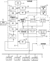
- FIG. 1 is a schematic hardware configuration diagram showing the main parts of a control device according to an embodiment of the present invention.
- the control device 1 of the present invention can be implemented as a control device that controls industrial machines such as machine tools and robots that have moving objects that move when driven by a motor.
- the control device 1 that controls a machine tool that processes a workpiece by controlling the relative positions of a tool and a workpiece will be described as an example.
- the non-volatile memory 14 is composed of, for example, a memory backed up by a battery (not shown) or an SSD (Solid State Drive), and retains its memory state even when the power to the control device 1 is turned off.
- the non-volatile memory 14 stores control programs and data read from the external device 72 via the interface 15, data and control programs input via the input device 71, and various data acquired from the industrial machine 3.
- the control programs and data stored in the non-volatile memory 14 may be expanded in the RAM 13 when executed/used.
- various system programs such as well-known analysis programs are written in advance in the ROM 12.
- the interface 15 is an interface for connecting the CPU 11 of the control device 1 to an external device 72 such as a USB memory, a compact flash (registered trademark), or an SD card.
- an external device 72 such as a USB memory, a compact flash (registered trademark), or an SD card.
- control programs and various data used to control the industrial machine 3 can be read from the external device 72.
- control programs and various data edited in the control device 1 can be stored in the external device 72.
- the PLC (Programmable Logic Controller) 16 outputs signals to the industrial machine 3 and its peripheral devices (for example, tool changers, actuators such as robots, sensors attached to the industrial machine 3, etc.) via the I/O unit 17 and controls them using a sequence program built into the control device 1.
- the PLC 16 also receives signals from various switches on an operation panel installed on the main body of the industrial machine 3 and from peripheral devices, etc., and passes them to the CPU 11 after performing the necessary signal processing.
- Display device 70 displays various data loaded into memory, data obtained as a result of executing control programs and system programs, etc., output via interface 18.
- input device 71 which is composed of a keyboard, pointing device, etc., passes commands and data based on operations by the operator to CPU 11 via interface 19.
- the interface 20 is an interface for connecting the CPU 11 of the control device 1 to a wired or wireless network 5.
- the network 5 may communicate using technologies such as serial communication such as RS-485, Ethernet (registered trademark), optical communication, wireless LAN, Wi-Fi (registered trademark), Bluetooth (registered trademark), etc.
- At least one computer 4, fog computer 6, cloud server 7, etc. are connected to the network 5, and data is exchanged between the network 5 and the control device 1.
- the spindle control circuit 60 receives a spindle rotation command and outputs a spindle speed signal to the spindle amplifier 61.
- the spindle amplifier 61 receives this spindle speed signal and rotates the spindle motor 62 of the industrial machine 3 at the commanded rotation speed to drive the spindle.
- a position coder 63 is connected to the spindle motor 62.
- the position coder 63 outputs a feedback pulse in synchronization with the rotation of the spindle, and the feedback pulse is read by the CPU 11.
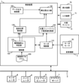
- FIG. 2 is a schematic block diagram showing the functions of the control device 1 according to the first embodiment of the present disclosure.
- Each function of the control device 1 according to this embodiment is realized by the CPU 11 of the control device 1 shown in FIG. 1 executing a system program and controlling the operation of each part of the control device 1.
- the control device 1 of this embodiment includes a control unit 100, a servo control unit 110, a drive shaft stop determination unit 120, a reference position holding unit 130, a position feedback integrated value collection unit 140, a data output control unit 150, and an actual position output unit 160.
- the RAM 13 to the non-volatile memory 14 of the control device 1 store a control program 200 for controlling the industrial machine 3.
- the control unit 100 has general functions required to control the industrial machine 3.
- the control unit 100 outputs a command to control the industrial machine 3 based on a given command.
- the control unit 100 analyzes the given command and outputs a position command to the servo control unit 110 for each control period to move each part of the industrial machine 3 along a specified axis based on the analysis result.
- the control unit 100 also analyzes the given spindle rotation command and outputs a rotation command for the spindle of the industrial machine 3 based on the analysis result.
- the control unit 100 updates the machine coordinate values of each axis it manages based on the output position command.
- the command to control the industrial machine 3 may be, for example, a command read from the control program 200.
- the command to control the industrial machine 3 may be a command input via the input device 71.
- the control unit 100 may refer to a specified control parameter that is set in advance in the RAM 13 or non-volatile memory 14.
- the control unit 100 may acquire predetermined feedback values related to the servo motor 50 and spindle motor 62 attached to the industrial machine 3 and use them for control.
- the drive shaft stop determination unit 120 automatically determines whether or not the operation of a specific drive shaft (servo motor 50) has stopped. If it determines that the operation of a drive shaft has stopped, it determines that the drive shaft has stopped and notifies the reference position holding unit 130 and the position feedback integrated value collection unit 140 to that effect. The determination of whether a drive shaft has stopped is made for each drive shaft.
- the drive shaft stop determination unit 120 may determine that the operation of the drive shaft has stopped under the conditions that the control program 200 is not running, that there is no axis movement command in manual mode, and that there are no other position commands such as axis control by the PLC 16 or external pulse input. Even when the control program 200 is running, for example, the drive shaft may be determined to have stopped when, after a command based on the control program 200 is output to the servo motor 50, the position deviation of the servo motor 50 is eliminated for a predetermined time Pst . Furthermore, the drive shaft may be determined to have stopped when, after a predetermined command such as reference return is executed, the position deviation of the servo motor 50 is eliminated for a predetermined time Pst .
- the reference position holding unit 130 receives a notification of the stop of a specific drive axis from the drive axis stop determination unit 120, and acquires the machine coordinate value B t1 at the stop time t1 of the drive axis from the control unit 100. Then, the acquired machine coordinate value B t1 is held as a reference position.
- the control unit 100 manages the machine coordinate values of each axis when the output of a position command is completed.
- the reference position holding unit 130 may acquire the machine coordinate values managed in this manner.
- the position feedback integrated value collection unit 140 constantly collects the position feedback integrated value for each drive axis input from the servo control unit 110. In addition, upon receiving a notification of drive axis stop from the drive axis stop determination unit 120, it holds the position feedback integrated value A t1 at the stop time t1 . The position feedback integrated value collection unit 140 collects the position feedback integrated value for each drive axis every control period of the servo control unit 110.
- the data output control unit 150 commands the actual position output unit 160 to output data relating to the actual position of the specified drive axis at a predetermined cycle from the time when a data output request relating to a specified drive axis is received from the computer 4, fog computer 6, cloud server 7, etc. In addition, after the time when the data output request is completed, the data output control unit 150 commands the actual position output unit 160 to stop outputting data relating to the actual position of the drive axis for which the request has been completed.
- the actual position output unit 160 outputs the actual position of the servo motor 50 at the time of output based on the reference position (machine coordinate value B t1 at the stop time t 1 ) held by the reference position holding unit 130, the position feedback integrated value A t1 at the stop time t 1 held by the position feedback integrated value collecting unit 140, and the position feedback integrated value at the time of output in response to a command from the data output control unit 150.
- the actual position output unit 160 outputs the actual positions of the drive axes to be output to the computer 4, fog computer 6, cloud server 7, etc. that has requested data output. At this time, the actual position output unit 160 may display and output the actual positions of the drive axes on the display device 70.
- the actual position P tn of a given drive axis at the output time t n can be calculated by the following formula 1.
- t1 is the most recent stop time
- Bt1 is the reference position (the mechanical coordinate value of the drive axis at the stop time t1 )
- At1 is the position feedback integrated value of the drive axis at the stop time t1
- tn is the output time
- Atn is the position feedback integrated value of the drive axis at the output time tn .
- the actual position output unit 160 may, for example, calculate and output the actual position of the drive shaft for each control period of the servo control unit 110. Also, the actual position of the drive shaft may be calculated and output for each period specified in the data output request.
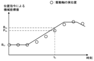
- FIGS. 3 is a graph illustrating the relationship between the machine coordinate value based on the position command and the actual position of the drive axis.
- the machine coordinate value managed by the control unit 100 is updated every time a position command is output to the servo control unit 110.
- the servo control unit 110 controls the position of the drive axis according to the input position command.
- the control device 1 In order to calculate the actual position of the drive axis at any timing regardless of this delay, the control device 1 according to this embodiment first automatically holds the machine coordinate value Bt1 at a timing when a position command for each drive axis is not being executed, i.e., at the stop time t1 of the drive axis, and also automatically holds the position feedback integrated value At1 at that time.
- the position feedback integrated value for a specific drive axis can be acquired for each control period of the servo control unit 110.
- the position feedback integrated value collector 140 collects the position feedback integrated values A t1 , A t2 , ..., A tn , A tn+1 , ... in association with times t 1 , t 2 , ..., t n , t n+1 , ... in each control period.
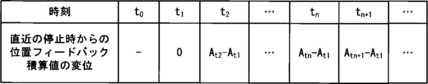
- FIG. 5 is a table showing an example of the amount of displacement of the position feedback integrated value from the most recent drive axis stop time t1 .
- the amount of displacement of the position feedback integrated value at times t1 , t2 , ..., tn , tn +1 , ... in each control period can be calculated as 0, (A t2 - A t1 ), ..., (A tn - A t1 ), (A tn+1 - A t1 ), ...
- the actual positions at times t1 , t2 , ..., tn , tn +1 , ... in each control period can be calculated as Bt1 , ( At2 - At1 )+ Bt1 , ..., ( Atn - At1 )+ Bt1 , (Atn +1 - At1 )+ Bt1 , ....
- the actual position output unit 160 calculates and outputs the actual position of the drive axis based on the machine coordinate value Bt1 at the most recent drive axis stop time t1 that is held, the position feedback integrated value At1 , and the current position feedback integrated value.
- the control device 1 which has the above configuration, automatically sets the reference position of each drive shaft when the drive shaft stops.
- the position feedback integrated value at the time when the drive shaft stops is automatically retained. Therefore, when collecting the actual positions of the drive shafts, the user can start acquiring the actual positions of the drive shafts at any timing without having to manually stop the drive shafts in advance.
- FIG. 7 is a schematic block diagram showing functions of the control device 1 according to the second embodiment of the present disclosure.
- Each function of the control device 1 according to this embodiment is realized by the CPU 11 of the control device 1 shown in FIG. 1 executing a system program and controlling the operation of each part of the control device 1, similar to the control device 1 according to the first embodiment.
- the control device 1 of this embodiment differs from the control device 1 of the first embodiment in the timing of collection of position feedback integrated values by the position feedback integrated value collection unit 140.
- the position feedback integrated value collection unit 140 included in the control device 1 of the first embodiment constantly collects the position feedback integrated values of each drive axis from the servo control unit 110.
- the position feedback integrated value collection unit 140 of this embodiment starts constant collection of position feedback integrated values for the drive axis to be outputted data at the timing when the data output control unit 150 receives a data output request from an external computer or the like and issues a command to output data.
- the position feedback integrated value A t1 at the time when each drive axis is stopped is acquired at the timing when the drive axis stop determination unit 120 determines that each drive axis is stopped.
- the data output control unit 150 When the data output control unit 150 according to this embodiment receives a data output request related to a specific drive axis from an external computer or the like, it instructs the position feedback integrated value collection unit 140 to start continuous collection of the position feedback integrated value related to that drive axis. It also instructs the actual position output unit 160 to output data at a predetermined interval from the time when the data output request related to that drive axis was received.
- the data output control unit 150 instructs the position feedback integrated value collection unit 140 to end the continuous collection of the position feedback integrated value related to the drive axis for which the request has been completed. It also instructs the actual position output unit 160 to stop outputting data related to the actual position of that drive axis.
- the control device 1 according to this embodiment which has the above configuration, can avoid constantly collecting unnecessary position feedback integrated values when there is no request to output data related to the actual position of the drive shaft. This makes it possible to conserve the calculation resources of the control device 1.
- a control device (1) includes a drive shaft stop determination unit (120) that automatically determines whether or not each drive shaft of an industrial machine (3) to be controlled is in a stopped state, a reference position holding unit (130) that acquires a machine coordinate value based on a position command for each drive shaft when the drive shaft stop determination unit (120) determines that the drive shaft is in a stopped state and holds the acquired machine coordinate value as a reference position, and a position feedback integrated value of the drive shaft that is constantly collected and, when the drive shaft stop determination unit (120) determines that the drive shaft is in a stopped state, a position feedback integrated value of each drive shaft when the drive shaft stop determination unit (120) determines that the drive shaft is in a stopped state, a reference position holding unit (130) that constantly collects a position feedback integrated value of the drive shaft and holds a position feedback of each drive shaft when the drive shaft stop determination unit (120) determines that the drive shaft is
- a position feedback integrated value collecting unit that holds an integrated position feedback value of the reference position of the drive shaft; a data output control unit (150) that commands the start of calculation and output processing of an actual position of a specified drive shaft; and an actual position output unit (160) that receives a command from the data output control unit (150) to start calculation and output of the actual position of a specified drive shaft, calculates the actual position of the drive shaft based on the reference position, the position feedback integrated value at the most recent time when the drive shaft was stopped that is held by the position feedback integrated value collecting unit (140), and the position feedback integrated value collected by the position feedback integrated value collecting unit (140), and outputs the calculated actual position of the drive shaft.
- the position feedback integrated value collection unit (140) starts a process of continuously collecting the position feedback integrated values of each drive shaft upon receiving an instruction from the data output control unit (150).
- a computer-readable recording medium includes a drive shaft stop determination unit (120) that automatically determines whether or not each drive shaft of an industrial machine (3) to be controlled is in a stopped state, a reference position holding unit (130) that, when the drive shaft stop determination unit (120) determines that the drive shaft is in a stopped state, acquires a machine coordinate value based on a position command for each drive shaft and holds the acquired machine coordinate value as a reference position, and a position feedback integrated value of the drive shaft is constantly collected, and, when the drive shaft stop determination unit (120) determines that the drive shaft is in a stopped state, a position feedback integrated value of each drive shaft at the time of stopping is stored.
- a data output control unit (150) that commands the start of calculation and output processing of an actual position of a specified drive shaft
- an actual position output unit (160) that receives a command from the data output control unit (150) to start calculation and output of the actual position of a specified drive shaft, calculates the actual position of the drive shaft based on the reference position, the position feedback integrated value at the most recent time when the drive shaft was stopped held by the position feedback integrated value collection unit (140), and the position feedback integrated value collected by the position feedback integrated value collection unit (140), and outputs the calculated actual position of the drive shaft.
- Reference Signs List 1 Control device 3 Industrial machine 4 Computer 5 Network 6 Fog computer 7 Cloud server 11 CPU 12 ROM 13 RAM 14 Non-volatile memory 15, 18, 19, 20 Interface 16 PLC 17 I/O unit 22 Bus 30 Axis control circuit 40 Servo amplifier 50 Servo motor 60 Spindle control circuit 61 Spindle amplifier 62 Spindle motor 63 Position coder 70 Display device 71 Input device 72 External device 100 Control unit 110 Servo control unit 120 Drive axis stop determination unit 130 Reference position holding unit 140 Position feedback integrated value collection unit 150 Data output control unit 160 Actual position output unit 200 Control program
Landscapes
- Engineering & Computer Science (AREA)
- Physics & Mathematics (AREA)
- General Physics & Mathematics (AREA)
- Automation & Control Theory (AREA)
- Human Computer Interaction (AREA)
- Manufacturing & Machinery (AREA)
- Mechanical Engineering (AREA)
- Numerical Control (AREA)
Abstract
本開示による制御装置は、制御対象となる産業機械のそれぞれの駆動軸が停止している状態であるか否かを自動的に判定する駆動軸停止判定部と、駆動軸が停止している状態であると判定された場合に、駆動軸毎の位置指令に基づく機械座標値を取得し、取得した機械座標値を基準位置として保持する基準位置保持部と、駆動軸の位置フィードバック積算値を常時収集すると共に、駆動軸が停止している状態であると判定された場合に、それぞれの駆動軸の停止時の位置フィードバック積算値を保持する位置フィードバック積算値収集部と、所定の駆動軸の実位置の算出及び出力処理の実行開始を指令するデータ出力制御部と、データ出力制御部からの指令を受けて、基準位置と、直近の駆動軸の停止時における位置フィードバック積算値、及び収集した位置フィードバック積算値に基づいて、駆動軸の実位置を算出して出力する実位置出力部と、を備える。
Description
本開示は、制御装置、及びコンピュータ読み取り可能な記録媒体に関する。
制御装置では、ユーザの解析目的に応じて、駆動軸(サーボモータ)の実際の位置(以下では、実位置とする)の推移を時系列データとして収集することがある。この時、制御装置は、サーボアンプ経由で駆動軸のモータの位置検出器からフィードバックされてきた移動量(パルス量)を積算した値(以下では、位置フィードバック積算値とする)を算出する。制御装置は、所定の機械座標の値を基準位置として、これと位置フィードバック積算値とに基づいて駆動軸の実位置を算出する(例えば、特許文献1など)。
この基準位置は、例えば駆動軸の動作が停止している状態において手動でワンショット指令などを実行することで取得した機械座標値を用いることができる。基準位置の設定は、駆動軸の動作が停止している状態で行う。駆動軸が動作している最中は、指令位置に対する実位置の遅れがあるため、位置指令により指令される機械座標値を取得したとしても、その時点での実位置の機械座標値とずれが生じるからである。
産業機械が配置される生産ラインは、なるべく生産動作を停止しないことが求められる。一方で、産業機械を制御する制御装置には複数ユーザが接続して異なるタイミングでデータの収集を依頼する場合がある。しかしながら、駆動軸の実位置に係る時系列データを取得するために、都度産業機械の動作を停止させて基準位置を設定していると、生産のサイクルタイムが延びてしまうという課題がある。
生産現場では、産業機械を停止させずに各駆動軸の実位置に係るデータを取得したいという要望がある。
生産現場では、産業機械を停止させずに各駆動軸の実位置に係るデータを取得したいという要望がある。
本開示による産業機械の制御装置は、駆動軸の動作が停止しているタイミングを制御部内で自動的に判断し、駆動軸停止時の位置指令の機械座標値を基準位置として設定する。また、位置フィードバック積算値については常時算出しておく。そして、ユーザからの要求に応じて、設定した基準位置に対して停止時からの位置フィードバック積算値を加算した駆動軸の実位置を出力することで、上記課題を解決する。
そして本開示の一態様は、制御対象となる産業機械のそれぞれの駆動軸が停止している状態であるか否かを自動的に判定する駆動軸停止判定部と、前記駆動軸停止判定部により前記駆動軸が停止している状態であると判定された場合に、駆動軸毎の位置指令に基づく機械座標値を取得し、取得した機械座標値を基準位置として保持する基準位置保持部と、前記駆動軸の位置フィードバック積算値を常時収集すると共に、前記駆動軸停止判定部により前記駆動軸が停止している状態であると判定された場合に、それぞれの前記駆動軸の停止時の位置フィードバック積算値を保持する位置フィードバック積算値収集部と、所定の駆動軸の実位置の算出及び出力処理の実行開始を指令するデータ出力制御部と、前記データ出力制御部から所定の駆動軸の実位置の算出及び出力開始の指令を受けて、前記基準位置と、前記位置フィードバック積算値収集部が保持する直近の前記駆動軸の停止時における位置フィードバック積算値、及び前記位置フィードバック積算値収集部が収集する位置フィードバック積算値に基づいて、前記駆動軸の実位置を算出し、算出した前記駆動軸の実位置を出力する実位置出力部と、を備える制御装置である。
以下、本発明の実施形態を図面と共に説明する。
[第1実施形態]
図1は本発明の一実施形態による制御装置の要部を示す概略的なハードウェア構成図である。本発明の制御装置1は、モータが駆動することで移動する移動対象を備えた工作機械やロボットなどの産業機械を制御する制御装置として実装することができる。以下では、工具とワークとの相対位置を制御することでワークを加工する工作機械を制御する制御装置1を例として説明する。
[第1実施形態]
図1は本発明の一実施形態による制御装置の要部を示す概略的なハードウェア構成図である。本発明の制御装置1は、モータが駆動することで移動する移動対象を備えた工作機械やロボットなどの産業機械を制御する制御装置として実装することができる。以下では、工具とワークとの相対位置を制御することでワークを加工する工作機械を制御する制御装置1を例として説明する。
本発明の制御装置1が備えるCPU11は、制御装置1を全体的に制御するプロセッサである。CPU11は、バス22を介してROM12に格納されたシステム・プログラムを読み出し、該システム・プログラムに従って制御装置1全体を制御する。RAM13には一時的な計算データや表示データ、及び外部から入力された各種データ等が一時的に格納される。
不揮発性メモリ14は、例えば図示しないバッテリでバックアップされたメモリやSSD(Solid State Drive)等で構成され、制御装置1の電源がオフされても記憶状態が保持される。不揮発性メモリ14には、インタフェース15を介して外部デバイス72から読み込まれた制御用プログラムやデータ、入力装置71を介して入力されたデータや制御用プログラム、産業機械3から取得される各データ等が記憶される。不揮発性メモリ14に記憶された制御用プログラムやデータは、実行時/利用時にはRAM13に展開されても良い。また、ROM12には、公知の解析プログラムなどの各種システム・プログラムが予め書き込まれている。
インタフェース15は、制御装置1のCPU11とUSBメモリ、コンパクトフラッシュ(登録商標)、SDカード等の外部デバイス72と接続するためのインタフェースである。外部デバイス72側からは、例えば産業機械3の制御に用いられる制御用プログラムや各種データ等を読み込むことができる。また、制御装置1内で編集した制御用プログラムや各種データ等は、外部デバイス72に対して記憶させることができる。PLC(プログラマブル・ロジック・コントローラ)16は、制御装置1に内蔵されたシーケンス・プログラムによって、産業機械3及び該産業機械3の周辺装置(例えば、工具交換装置や、ロボット等のアクチュエータ、産業機械3に取付けられているセンサ等)にI/Oユニット17を介して信号を出力し制御する。また、PLC16は、産業機械3の本体に配備された操作盤の各種スイッチや周辺装置等からの信号を受け、必要な信号処理をした後、CPU11に渡す。
表示装置70には、メモリ上に読み込まれた各データ、制御用プログラムやシステム・プログラム等が実行された結果として得られたデータ等が、インタフェース18を介して出力されて表示される。また、キーボードやポインティングデバイス等から構成される入力装置71は、インタフェース19を介して作業者による操作に基づく指令,データ等をCPU11に渡す。
インタフェース20は、制御装置1のCPU11と有線乃至無線のネットワーク5とを接続するためのインタフェースである。ネットワーク5は、例えばRS-485等のシリアル通信、Ethernet(登録商標)通信、光通信、無線LAN、Wi-Fi(登録商標)、Bluetooth(登録商標)等の技術を用いて通信をするものであってよい。ネットワーク5には、少なくとも1つのコンピュータ4、フォグコンピュータ6、クラウドサーバ7等が接続され、制御装置1との間で相互にデータのやり取りを行っている。
産業機械3が備える駆動軸を制御するための軸制御回路30は、CPU11からの駆動軸の位置指令を受けて、該駆動軸に対する指令をサーボアンプ40に出力する。サーボアンプ40はこの指令を受けて駆動軸であるサーボモータ50を駆動し、産業機械3が備える各部をそれぞれの軸に沿って移動させる。それぞれのサーボモータ50は位置検出器を内蔵し、この位置検出器からの位置フィードバック信号を軸制御回路30にフィードバックする。軸制御回路30は、位置このフィードバック信号に基づいてサーボモータ50のフィードバック制御を行う。なお、図1のハードウェア構成図では、軸制御回路30、サーボアンプ40、サーボモータ50は1つずつしか示されていないが、実際には制御対象となる産業機械3に備えられた軸の数だけ用意される。例えば、一般的な直線3軸を備えた工作機械を制御する場合には、工具が取り付けられた主軸とワークとを直線3軸(X軸,Y軸,Z軸)方向に相対的に移動させる3組の軸制御回路30、サーボアンプ40、サーボモータ50が用意される。
スピンドル制御回路60は、主軸回転指令を受け、スピンドルアンプ61にスピンドル速度信号を出力する。スピンドルアンプ61はこのスピンドル速度信号を受けて、産業機械3のスピンドルモータ62を指令された回転速度で回転させ、主軸を駆動する。スピンドルモータ62にはポジションコーダ63が結合されている。ポジションコーダ63が主軸の回転に同期して帰還パルスを出力し、その帰還パルスはCPU11によって読み取られる。
図2は、本開示の第1実施形態による制御装置1が備える機能を概略的なブロック図として示したものである。本実施形態による制御装置1が備える各機能は、図1に示した制御装置1が備えるCPU11がシステム・プログラムを実行し、制御装置1の各部の動作を制御することにより実現される。
本実施形態の制御装置1は、制御部100、サーボ制御部110、駆動軸停止判定部120、基準位置保持部130、位置フィードバック積算値収集部140、データ出力制御部150、実位置出力部160を備える。また、制御装置1のRAM13乃至不揮発性メモリ14には、産業機械3を制御するための制御用プログラム200が記憶される。
制御部100は、産業機械3を制御するために必要とされる一般的な機能を備えている。そして、与えられた指令に基づいて産業機械3を制御する指令を出力する。例えば、制御部100は、与えられた指令を解析し、その解析結果に基づいて産業機械3が備える各部を所定の軸に沿って移動させる位置指令を制御周期毎にサーボ制御部110へと出力する。また、与えられた主軸回転指令を解析し、その解析結果に基づいて産業機械3が備える主軸の回転指令を出力する。制御部100は、サーボ制御部110に対して制御周期毎に位置指令を出力すると、管理しているそれぞれの軸の機械座標値を出力した位置指令に基づいて更新する。産業機械3を制御する指令は、例えば制御用プログラム200から読み出される指令であってよい。また、産業機械3を制御する指令は、入力装置71を介して入力された指令であってよい。制御部100は、産業機械3の制御を行うに際して、予めRAM13乃至不揮発性メモリ14に設定されている所定の制御用パラメータを参照してよい。制御部100は、産業機械3に取り付けられたサーボモータ50やスピンドルモータ62に係る所定のフィードバック値を取得して制御に用いるようにしてもよい。
サーボ制御部110は、制御部100から入力された指令に基づいて、所定の軸に係るサーボモータ50を駆動することで、産業機械3の各部を所定の軸に沿って移動させる。また、サーボ制御部110は、サーボモータ50の動作中に、サーボアンプ40を経由してサーボモータ50の位置検出器からフィードバックされる位置の変化に係る移動量を取得する。移動量はサーボモータ50の移動方向に応じて正負の値を取り得る。サーボ制御部110は、取得した移動量を駆動軸毎に積算した位置フィードバック積算値を算出する。算出した位置フィードバック積算値は、サーボモータ50の制御に用いられると共に、位置フィードバック積算値収集部140へと出力される。
駆動軸停止判定部120は、所定の駆動軸(サーボモータ50)の動作が停止している状態であるか否かを自動的に判定する。そして、駆動軸の動作が停止している状態であると判定した場合、当該駆動軸が停止しているとして、その旨を基準位置保持部130および位置フィードバック積算値収集部140へと通知する。駆動軸の停止の判定は、それぞれの駆動軸毎に行われる。
駆動軸停止判定部120は、例えば制御用プログラム200の運転中でないこと、手動モードでの軸移動指令がないこと、およびPLC16による軸制御や外部パルス入力など他の位置指令がないことなどを条件として、駆動軸の動作が停止していると判定するようにしてよい。また、制御用プログラム200の運転中などであっても、例えば該制御用プログラム200に基づく指令がサーボモータ50に出力された後であって、該サーボモータ50の位置偏差が解消された状態が予め定めた所定時間Pstの間継続した場合に、駆動軸の動作が停止していると判定するようにしてよい。更に、例えばリファレンス復帰などのような所定の指令の実行後に、該サーボモータ50の位置偏差が解消された状態が予め定めた所定時間Pstの間継続した場合に、駆動軸の動作が停止していると判定するようにしてよい。
基準位置保持部130は、駆動軸停止判定部120から所定の駆動軸に係る停止の通知を受けて、当該駆動軸の停止時刻t1における機械座標値Bt1を制御部100から取得する。そして、取得した機械座標値Bt1を基準位置として保持する。制御部100は、位置指令の出力が完了した時のそれぞれの軸の機械座標値を管理している。基準位置保持部130は、そのようにして管理された機械座標値を取得するようにすればよい。
位置フィードバック積算値収集部140は、サーボ制御部110から入力された駆動軸毎の位置フィードバック積算値を常時収集する。また、駆動軸停止判定部120からの駆動軸停止の通知を受けて、停止時刻t1の位置フィードバック積算値At1を保持する。位置フィードバック積算値収集部140による駆動軸毎の位置フィードバック積算値の収集は、サーボ制御部110の制御周期毎に行われる。
データ出力制御部150は、コンピュータ4、フォグコンピュータ6、クラウドサーバ7などから所定の駆動軸に係るデータ出力依頼があった時刻から、所定周期毎に指定された駆動軸の実位置に係るデータを出力するように実位置出力部160へと指令する。また、データ出力依頼が終了した時刻以降は、依頼が終了した駆動軸の実位置に係るデータの出力を停止するように実位置出力部160へと指令する。
実位置出力部160は、データ出力制御部150からの指令に応じて、基準位置保持部130が保持する基準位置(停止時刻t1の機械座標値Bt1)と、位置フィードバック積算値収集部140が保持する停止時刻t1の位置フィードバック積算値At1、および出力時における位置フィードバック積算値とに基づいて、出力時におけるサーボモータ50の実位置を出力する。実位置出力部160は、データ出力依頼があったコンピュータ4、フォグコンピュータ6、クラウドサーバ7などに対して出力対象とされる駆動軸の実位置を出力する。この時、実位置出力部160は、表示装置70に対して各駆動軸の実位置を表示出力するようにしてよい。出力時刻tnにおける所定の駆動軸の実位置Ptnは、以下の数1式で算出することができる。なお、数1式において、t1は直近の停止時刻、Bt1は基準位置(停止時刻t1における駆動軸の機械座標値)、At1は停止時刻t1における駆動軸の位置フィードバック積算値、tnは出力時刻、Atnは出力時刻tnにおける駆動軸の位置フィードバック積算値である。
実位置出力部160は、例えばサーボ制御部110の制御周期毎に駆動軸の実位置を算出して出力するようにしてもよい。また、データ出力依頼で指定された周期毎に駆動軸の実位置を算出して出力するようにしてもよい。
以下では、図3~図6を用いて、本実施形態による制御装置1の動作の概略的な流れを説明する。
図3は、位置指令に基づく機械座標値と駆動軸の実位置との関係を例示するグラフである。制御部100が管理する機械座標値は、サーボ制御部110に対して位置指令が出力されるたびに更新される。そして、サーボ制御部110は入力された位置指令に従って駆動軸の位置を制御する。制御部100から位置指令が出力されるタイミングと、指令された位置への駆動軸の移動が終了するタイミングとの間には、常にサーボ遅れなどの遅れが存在する。そのため、位置指令が実行されている所定の時刻tnに着目すると、制御部100で管理される位置指令に基づく機械座標値Btnに対して、移動中の駆動軸の実位置Ptnは、常に遅れることになる。
図3は、位置指令に基づく機械座標値と駆動軸の実位置との関係を例示するグラフである。制御部100が管理する機械座標値は、サーボ制御部110に対して位置指令が出力されるたびに更新される。そして、サーボ制御部110は入力された位置指令に従って駆動軸の位置を制御する。制御部100から位置指令が出力されるタイミングと、指令された位置への駆動軸の移動が終了するタイミングとの間には、常にサーボ遅れなどの遅れが存在する。そのため、位置指令が実行されている所定の時刻tnに着目すると、制御部100で管理される位置指令に基づく機械座標値Btnに対して、移動中の駆動軸の実位置Ptnは、常に遅れることになる。
本実施形態による制御装置1は、この遅れによらず任意のタイミングで駆動軸の実位置を算出するために、まず、それぞれの駆動軸に対する位置指令が実行されていないタイミング、即ち駆動軸の停止時刻t1における機械座標値Bt1を自動的に保持すると共に、その時の位置フィードバック積算値At1を自動的に保持する。
図4は、位置フィードバック積算値の推移を例示するテーブルである。所定の駆動軸に係る位置フィードバック積算値はサーボ制御部110の制御周期毎に取得できる。位置フィードバック積算値収集部140は、それぞれの制御周期における時刻t1、t2、…、tn、tn+1、…と関連付けて、位置フィードバック積算値At1、At2、…、Atn、Atn+1、…を収集する。
図5は、直近の駆動軸の停止時刻t1からの位置フィードバック積算値の変位量を例示するテーブルである。それぞれの制御周期における時刻t1、t2、…、tn、tn+1、…における位置フィードバック積算値の変位量は、それぞれ0、(At2-At1)、…、(Atn-At1)、(Atn+1-At1)、…として算出することができる。
図6は、駆動軸の実位置の推移を例示するテーブルである。それぞれの制御周期における時刻t1、t2、…、tn、tn+1、…における実位置は、それぞれBt1、(At2-At1)+Bt1、…、(Atn-At1)+Bt1、(Atn+1-At1)+Bt1、…として算出することができる。実位置出力部160は、保持された直近の駆動軸の停止時刻t1における機械座標値Bt1と、位置フィードバック積算値At1、及び現時点での位置フィードバック積算値とに基づいて、駆動軸の実位置を算出し出力する。
上記構成を備えた本実施形態による制御装置1は、それぞれの駆動軸が停止しているタイミングでそれぞれの駆動軸の基準位置の設定が自動的に行われる。また、それぞれの駆動軸が停止しているタイミングでそれぞれの駆動軸の停止時の位置フィードバック積算値が自動的に保持される。そのため、駆動軸の実位置を収集する際に、ユーザは事前に手動で駆動軸を停止させることなく、任意のタイミングで駆動軸の実位置の取得を開始することができる。
[第2実施形態]
図7は、本開示の第2実施形態による制御装置1が備える機能を概略的なブロック図として示したものである。本実施形態による制御装置1が備える各機能は、第1実施形態による制御装置1と同様に、図1に示した制御装置1が備えるCPU11がシステム・プログラムを実行し、制御装置1の各部の動作を制御することにより実現される。
図7は、本開示の第2実施形態による制御装置1が備える機能を概略的なブロック図として示したものである。本実施形態による制御装置1が備える各機能は、第1実施形態による制御装置1と同様に、図1に示した制御装置1が備えるCPU11がシステム・プログラムを実行し、制御装置1の各部の動作を制御することにより実現される。
本実施形態の制御装置1は、位置フィードバック積算値収集部140による位置フィードバック積算値の収集のタイミングが第1実施形態による制御装置1と異なる。第1実施形態による制御装置1が備える位置フィードバック積算値収集部140は、常にそれぞれの駆動軸の位置フィードバック積算値をサーボ制御部110から収集していた。これに対して、本実施形態による位置フィードバック積算値収集部140は、外部のコンピュータ等からのデータ出力依頼を受けてデータ出力制御部150がデータの出力を行う旨を指令したタイミングで、データ出力の対象となる駆動軸について、位置フィードバック積算値の常時収集を開始する。また、駆動軸停止判定部120によりそれぞれの駆動軸が停止している旨が判定されたタイミングで各駆動軸の停止時の位置フィードバック積算値At1を取得する。
本実施形態によるデータ出力制御部150は、外部のコンピュータ等から所定の駆動軸に係るデータ出力依頼を受けた場合、該駆動軸に係る位置フィードバック積算値の常時収集を開始するように位置フィードバック積算値収集部140へと指令する。また、該駆動軸に係るデータ出力依頼があった時刻から、所定周期毎にデータの出力を行うように実位置出力部160へ指令する。
一方、データ出力制御部150は、データ出力依頼が終了した時刻以降は、依頼が終了した駆動軸に係る位置フィードバック積算値の常時収集を終了するように位置フィードバック積算値収集部140へと指令する。また、該駆動軸の実位置に係るデータの出力を停止するように実位置出力部160へと指令する。
上記構成を備えた本実施形態による制御装置1は、駆動軸の実位置に係るデータ出力依頼が無い場合に、無駄な位置フィードバック積算値の常時収集を行わないようにすることができる。そのため、制御装置1の計算リソースを節約することができる。
以上、本開示の実施形態について詳述したが、本開示は上述した個々の実施形態に限定されるものではない。これらの実施形態は、発明の要旨を逸脱しない範囲で、または、請求の範囲に記載された内容とその均等物から導き出される本開示の思想および趣旨を逸脱しない範囲で、種々の追加、置き換え、変更、部分的削除等が可能である。例えば、上述した実施形態において、各動作の順序や各処理の順序は、一例として示したものであり、これらに限定されるものではない。また、上述した実施形態の説明に数値又は数式が用いられている場合も同様である。
以下に、本開示の実施形態に係る付記を示す。
(付記1)
本開示の一態様による制御装置(1)は、制御対象となる産業機械(3)のそれぞれの駆動軸が停止している状態であるか否かを自動的に判定する駆動軸停止判定部(120)と、前記駆動軸停止判定部(120)により前記駆動軸が停止している状態であると判定された場合に、駆動軸毎の位置指令に基づく機械座標値を取得し、取得した機械座標値を基準位置として保持する基準位置保持部(130)と、前記駆動軸の位置フィードバック積算値を常時収集すると共に、前記駆動軸停止判定部(120)により前記駆動軸が停止している状態であると判定された場合に、それぞれの前記駆動軸の停止時の位置フィードバック積算値を保持する位置フィードバック積算値収集部(140)と、所定の駆動軸の実位置の算出及び出力処理の実行開始を指令するデータ出力制御部(150)と、前記データ出力制御部(150)から所定の駆動軸の実位置の算出及び出力開始の指令を受けて、前記基準位置と、前記位置フィードバック積算値収集部(140)が保持する直近の前記駆動軸の停止時における位置フィードバック積算値、及び前記位置フィードバック積算値収集部(140)が収集する位置フィードバック積算値に基づいて、前記駆動軸の実位置を算出し、算出した前記駆動軸の実位置を出力する実位置出力部(160)と、を備える。
(付記2)
本開示の他の態様による制御装置(1)は、前記位置フィードバック積算値収集部(140)は、それぞれの駆動軸の位置フィードバック積算値の常時収集処理を、前記データ出力制御部(150)から指令を受けて開始する。
本開示の他の態様による制御装置(1)は、前記位置フィードバック積算値収集部(140)は、それぞれの駆動軸の位置フィードバック積算値の常時収集処理を、前記データ出力制御部(150)から指令を受けて開始する。
(付記3)
本開示の一態様によるコンピュータ読み取り可能な記録媒体は、制御対象となる産業機械(3)のそれぞれの駆動軸が停止している状態であるか否かを自動的に判定する駆動軸停止判定部(120)、前記駆動軸停止判定部(120)により前記駆動軸が停止している状態であると判定された場合に、駆動軸毎の位置指令に基づく機械座標値を取得し、取得した機械座標値を基準位置として保持する基準位置保持部(130)、前記駆動軸の位置フィードバック積算値を常時収集すると共に、前記駆動軸停止判定部(120)により前記駆動軸が停止している状態であると判定された場合に、それぞれの前記駆動軸の停止時の位置フィードバック積算値を保持する位置フィードバック積算値収集部(140)、所定の駆動軸の実位置の算出及び出力処理の実行開始を指令するデータ出力制御部(150)、前記データ出力制御部(150)から所定の駆動軸の実位置の算出及び出力開始の指令を受けて、前記基準位置と、前記位置フィードバック積算値収集部(140)が保持する直近の前記駆動軸の停止時における位置フィードバック積算値、及び前記位置フィードバック積算値収集部(140)が収集する位置フィードバック積算値に基づいて、前記駆動軸の実位置を算出し、算出した前記駆動軸の実位置を出力する実位置出力部(160)、としてコンピュータを機能させるプログラムを記録する。
本開示の一態様によるコンピュータ読み取り可能な記録媒体は、制御対象となる産業機械(3)のそれぞれの駆動軸が停止している状態であるか否かを自動的に判定する駆動軸停止判定部(120)、前記駆動軸停止判定部(120)により前記駆動軸が停止している状態であると判定された場合に、駆動軸毎の位置指令に基づく機械座標値を取得し、取得した機械座標値を基準位置として保持する基準位置保持部(130)、前記駆動軸の位置フィードバック積算値を常時収集すると共に、前記駆動軸停止判定部(120)により前記駆動軸が停止している状態であると判定された場合に、それぞれの前記駆動軸の停止時の位置フィードバック積算値を保持する位置フィードバック積算値収集部(140)、所定の駆動軸の実位置の算出及び出力処理の実行開始を指令するデータ出力制御部(150)、前記データ出力制御部(150)から所定の駆動軸の実位置の算出及び出力開始の指令を受けて、前記基準位置と、前記位置フィードバック積算値収集部(140)が保持する直近の前記駆動軸の停止時における位置フィードバック積算値、及び前記位置フィードバック積算値収集部(140)が収集する位置フィードバック積算値に基づいて、前記駆動軸の実位置を算出し、算出した前記駆動軸の実位置を出力する実位置出力部(160)、としてコンピュータを機能させるプログラムを記録する。
1 制御装置
3 産業機械
4 コンピュータ
5 ネットワーク
6 フォグコンピュータ
7 クラウドサーバ
11 CPU
12 ROM
13 RAM
14 不揮発性メモリ
15,18,19,20 インタフェース
16 PLC
17 I/Oユニット
22 バス
30 軸制御回路
40 サーボアンプ
50 サーボモータ
60 スピンドル制御回路
61 スピンドルアンプ
62 スピンドルモータ
63 ポジションコーダ
70 表示装置
71 入力装置
72 外部デバイス
100 制御部
110 サーボ制御部
120 駆動軸停止判定部
130 基準位置保持部
140 位置フィードバック積算値収集部
150 データ出力制御部
160 実位置出力部
200 制御用プログラム
Claims (3)
- 制御対象となる産業機械のそれぞれの駆動軸が停止している状態であるか否かを自動的に判定する駆動軸停止判定部と、
前記駆動軸停止判定部により前記駆動軸が停止している状態であると判定された場合に、駆動軸毎の位置指令に基づく機械座標値を取得し、取得した機械座標値を基準位置として保持する基準位置保持部と、
前記駆動軸の位置フィードバック積算値を常時収集すると共に、前記駆動軸停止判定部により前記駆動軸が停止している状態であると判定された場合に、それぞれの前記駆動軸の停止時の位置フィードバック積算値を保持する位置フィードバック積算値収集部と、
所定の駆動軸の実位置の算出及び出力処理の実行開始を指令するデータ出力制御部と、
前記データ出力制御部から所定の駆動軸の実位置の算出及び出力開始の指令を受けて、前記基準位置と、前記位置フィードバック積算値収集部が保持する直近の前記駆動軸の停止時における位置フィードバック積算値、及び前記位置フィードバック積算値収集部が収集する位置フィードバック積算値に基づいて、前記駆動軸の実位置を算出し、算出した前記駆動軸の実位置を出力する実位置出力部と、
を備える制御装置。 - 前記位置フィードバック積算値収集部は、それぞれの駆動軸の位置フィードバック積算値の常時収集処理を、前記データ出力制御部から指令を受けて開始する、
請求項1記載の制御装置。 - 制御対象となる産業機械のそれぞれの駆動軸が停止している状態であるか否かを自動的に判定する駆動軸停止判定部、
前記駆動軸停止判定部により前記駆動軸が停止している状態であると判定された場合に、駆動軸毎の位置指令に基づく機械座標値を取得し、取得した機械座標値を基準位置として保持する基準位置保持部、
前記駆動軸の位置フィードバック積算値を常時収集すると共に、前記駆動軸停止判定部により前記駆動軸が停止している状態であると判定された場合に、それぞれの前記駆動軸の停止時の位置フィードバック積算値を保持する位置フィードバック積算値収集部、
所定の駆動軸の実位置の算出及び出力処理の実行開始を指令するデータ出力制御部、
前記データ出力制御部から所定の駆動軸の実位置の算出及び出力開始の指令を受けて、前記基準位置と、前記位置フィードバック積算値収集部が保持する直近の前記駆動軸の停止時における位置フィードバック積算値、及び前記位置フィードバック積算値収集部が収集する位置フィードバック積算値に基づいて、前記駆動軸の実位置を算出し、算出した前記駆動軸の実位置を出力する実位置出力部、
としてコンピュータを機能させるプログラムを記録したコンピュータ読み取り可能な記録媒体。
Priority Applications (2)
| Application Number | Priority Date | Filing Date | Title |
|---|---|---|---|
| JP2025509597A JPWO2024202012A1 (ja) | 2023-03-31 | 2023-03-31 | |
| PCT/JP2023/013579 WO2024202012A1 (ja) | 2023-03-31 | 2023-03-31 | 制御装置、及びコンピュータ読み取り可能な記録媒体 |
Applications Claiming Priority (1)
| Application Number | Priority Date | Filing Date | Title |
|---|---|---|---|
| PCT/JP2023/013579 WO2024202012A1 (ja) | 2023-03-31 | 2023-03-31 | 制御装置、及びコンピュータ読み取り可能な記録媒体 |
Publications (1)
| Publication Number | Publication Date |
|---|---|
| WO2024202012A1 true WO2024202012A1 (ja) | 2024-10-03 |
Family
ID=92904538
Family Applications (1)
| Application Number | Title | Priority Date | Filing Date |
|---|---|---|---|
| PCT/JP2023/013579 Ceased WO2024202012A1 (ja) | 2023-03-31 | 2023-03-31 | 制御装置、及びコンピュータ読み取り可能な記録媒体 |
Country Status (2)
| Country | Link |
|---|---|
| JP (1) | JPWO2024202012A1 (ja) |
| WO (1) | WO2024202012A1 (ja) |
Citations (7)
| Publication number | Priority date | Publication date | Assignee | Title |
|---|---|---|---|---|
| JPH07281750A (ja) * | 1994-04-07 | 1995-10-27 | Nissan Motor Co Ltd | Agvの走行制御装置 |
| JPH08129409A (ja) * | 1994-10-28 | 1996-05-21 | Yaskawa Electric Corp | ロボットの制御装置 |
| JPH0944252A (ja) * | 1995-07-26 | 1997-02-14 | Koyo Electron Ind Co Ltd | 位置決め装置 |
| JPH10254524A (ja) * | 1997-03-10 | 1998-09-25 | Fanuc Ltd | 機械の制御装置におけるユニット間通信方法 |
| JP2010049361A (ja) * | 2008-08-19 | 2010-03-04 | Fanuc Ltd | 理論機械位置算出手段を有する数値制御装置 |
| JP2013250636A (ja) * | 2012-05-30 | 2013-12-12 | Fanuc Ltd | 加工処理の評価を行うための情報を表示する表示部を備えた数値制御装置 |
| JP2013257809A (ja) * | 2012-06-14 | 2013-12-26 | Fanuc Ltd | 工作機械の工具ベクトルを表示する工具軌跡表示装置 |
-
2023
- 2023-03-31 JP JP2025509597A patent/JPWO2024202012A1/ja active Pending
- 2023-03-31 WO PCT/JP2023/013579 patent/WO2024202012A1/ja not_active Ceased
Patent Citations (7)
| Publication number | Priority date | Publication date | Assignee | Title |
|---|---|---|---|---|
| JPH07281750A (ja) * | 1994-04-07 | 1995-10-27 | Nissan Motor Co Ltd | Agvの走行制御装置 |
| JPH08129409A (ja) * | 1994-10-28 | 1996-05-21 | Yaskawa Electric Corp | ロボットの制御装置 |
| JPH0944252A (ja) * | 1995-07-26 | 1997-02-14 | Koyo Electron Ind Co Ltd | 位置決め装置 |
| JPH10254524A (ja) * | 1997-03-10 | 1998-09-25 | Fanuc Ltd | 機械の制御装置におけるユニット間通信方法 |
| JP2010049361A (ja) * | 2008-08-19 | 2010-03-04 | Fanuc Ltd | 理論機械位置算出手段を有する数値制御装置 |
| JP2013250636A (ja) * | 2012-05-30 | 2013-12-12 | Fanuc Ltd | 加工処理の評価を行うための情報を表示する表示部を備えた数値制御装置 |
| JP2013257809A (ja) * | 2012-06-14 | 2013-12-26 | Fanuc Ltd | 工作機械の工具ベクトルを表示する工具軌跡表示装置 |
Also Published As
| Publication number | Publication date |
|---|---|
| JPWO2024202012A1 (ja) | 2024-10-03 |
Similar Documents
| Publication | Publication Date | Title |
|---|---|---|
| CN102385343B (zh) | 使加工高精度化的伺服控制系统 | |
| CN110405532B (zh) | 工具选定装置以及机器学习装置 | |
| JP6740199B2 (ja) | 数値制御装置、cnc工作機械、数値制御方法及び数値制御用プログラム | |
| JP2020071734A (ja) | 数値制御装置 | |
| JP2003303005A (ja) | 数値制御装置 | |
| US9471058B2 (en) | Data acquisition device for acquiring cause of stoppage of drive axis and information relating thereto | |
| CN112099435B (zh) | 诊断装置以及诊断方法 | |
| JP4802170B2 (ja) | 加工時間算出装置およびそのプログラム | |
| JP2013152698A (ja) | 補正データを考慮した軌跡表示装置 | |
| US9631632B2 (en) | Impeller having blade having blade surface made up of line elements and method of machining the impeller | |
| JP2006227886A (ja) | サーボ制御装置及びサーボ系の調整方法 | |
| WO2024232063A1 (ja) | 制御装置及びコンピュータ読み取り可能な記録媒体 | |
| US12259703B2 (en) | Control device | |
| JPWO2012164740A1 (ja) | 多軸モータ駆動システム及び多軸モータ駆動装置 | |
| CN111190391A (zh) | 数值控制装置 | |
| JP4796936B2 (ja) | 加工制御装置 | |
| JP2019185467A (ja) | 設定装置及び設定プログラム | |
| JPH03196310A (ja) | 数値制御装置の表示方式 | |
| WO2024202012A1 (ja) | 制御装置、及びコンピュータ読み取り可能な記録媒体 | |
| EP1403747A2 (en) | Numerical controller | |
| EP1267236A1 (en) | Method and apparatus for setting moving data in a machine tool | |
| JP6316919B2 (ja) | 工作機械の数値制御装置 | |
| US10802464B2 (en) | Numerical controller | |
| JP4282632B2 (ja) | テーブル形式データで運転を行う数値制御装置 | |
| JP7175340B2 (ja) | 工作機械、情報処理装置および情報処理プログラム |
Legal Events
| Date | Code | Title | Description |
|---|---|---|---|
| 121 | Ep: the epo has been informed by wipo that ep was designated in this application |
Ref document number: 23930647 Country of ref document: EP Kind code of ref document: A1 |
|
| WWE | Wipo information: entry into national phase |
Ref document number: 2025509597 Country of ref document: JP |
|
| NENP | Non-entry into the national phase |
Ref country code: DE |
|
| 122 | Ep: pct application non-entry in european phase |
Ref document number: 23930647 Country of ref document: EP Kind code of ref document: A1 |