WO2024202479A1 - 車両用駆動装置 - Google Patents
車両用駆動装置 Download PDFInfo
- Publication number
- WO2024202479A1 WO2024202479A1 PCT/JP2024/002370 JP2024002370W WO2024202479A1 WO 2024202479 A1 WO2024202479 A1 WO 2024202479A1 JP 2024002370 W JP2024002370 W JP 2024002370W WO 2024202479 A1 WO2024202479 A1 WO 2024202479A1
- Authority
- WO
- WIPO (PCT)
- Prior art keywords
- oil
- pump
- rotor
- vehicle
- control device
- Prior art date
- Legal status (The legal status is an assumption and is not a legal conclusion. Google has not performed a legal analysis and makes no representation as to the accuracy of the status listed.)
- Ceased
Links
Images





Classifications
-
- H—ELECTRICITY
- H02—GENERATION; CONVERSION OR DISTRIBUTION OF ELECTRIC POWER
- H02K—DYNAMO-ELECTRIC MACHINES
- H02K9/00—Arrangements for cooling or ventilating
- H02K9/19—Arrangements for cooling or ventilating for machines with closed casing and closed-circuit cooling using a liquid cooling medium, e.g. oil
-
- B—PERFORMING OPERATIONS; TRANSPORTING
- B60—VEHICLES IN GENERAL
- B60L—PROPULSION OF ELECTRICALLY-PROPELLED VEHICLES; SUPPLYING ELECTRIC POWER FOR AUXILIARY EQUIPMENT OF ELECTRICALLY-PROPELLED VEHICLES; ELECTRODYNAMIC BRAKE SYSTEMS FOR VEHICLES IN GENERAL; MAGNETIC SUSPENSION OR LEVITATION FOR VEHICLES; MONITORING OPERATING VARIABLES OF ELECTRICALLY-PROPELLED VEHICLES; ELECTRIC SAFETY DEVICES FOR ELECTRICALLY-PROPELLED VEHICLES
- B60L1/00—Supplying electric power to auxiliary equipment of vehicles
- B60L1/003—Supplying electric power to auxiliary equipment of vehicles to auxiliary motors, e.g. for pumps, compressors
-
- F—MECHANICAL ENGINEERING; LIGHTING; HEATING; WEAPONS; BLASTING
- F16—ENGINEERING ELEMENTS AND UNITS; GENERAL MEASURES FOR PRODUCING AND MAINTAINING EFFECTIVE FUNCTIONING OF MACHINES OR INSTALLATIONS; THERMAL INSULATION IN GENERAL
- F16H—GEARING
- F16H57/00—General details of gearing
- F16H57/04—Features relating to lubrication or cooling or heating
- F16H57/042—Guidance of lubricant
- F16H57/0421—Guidance of lubricant on or within the casing, e.g. shields or baffles for collecting lubricant, tubes, pipes, grooves, channels or the like
- F16H57/0424—Lubricant guiding means in the wall of or integrated with the casing, e.g. grooves, channels, holes
-
- F—MECHANICAL ENGINEERING; LIGHTING; HEATING; WEAPONS; BLASTING
- F16—ENGINEERING ELEMENTS AND UNITS; GENERAL MEASURES FOR PRODUCING AND MAINTAINING EFFECTIVE FUNCTIONING OF MACHINES OR INSTALLATIONS; THERMAL INSULATION IN GENERAL
- F16H—GEARING
- F16H57/00—General details of gearing
- F16H57/04—Features relating to lubrication or cooling or heating
- F16H57/0457—Splash lubrication
-
- F—MECHANICAL ENGINEERING; LIGHTING; HEATING; WEAPONS; BLASTING
- F16—ENGINEERING ELEMENTS AND UNITS; GENERAL MEASURES FOR PRODUCING AND MAINTAINING EFFECTIVE FUNCTIONING OF MACHINES OR INSTALLATIONS; THERMAL INSULATION IN GENERAL
- F16H—GEARING
- F16H57/00—General details of gearing
- F16H57/04—Features relating to lubrication or cooling or heating
- F16H57/0467—Elements of gearings to be lubricated, cooled or heated
- F16H57/0469—Bearings or seals
- F16H57/0471—Bearing
-
- F—MECHANICAL ENGINEERING; LIGHTING; HEATING; WEAPONS; BLASTING
- F16—ENGINEERING ELEMENTS AND UNITS; GENERAL MEASURES FOR PRODUCING AND MAINTAINING EFFECTIVE FUNCTIONING OF MACHINES OR INSTALLATIONS; THERMAL INSULATION IN GENERAL
- F16H—GEARING
- F16H57/00—General details of gearing
- F16H57/04—Features relating to lubrication or cooling or heating
- F16H57/0467—Elements of gearings to be lubricated, cooled or heated
- F16H57/0476—Electric machines and gearing, i.e. joint lubrication or cooling or heating thereof
-
- F—MECHANICAL ENGINEERING; LIGHTING; HEATING; WEAPONS; BLASTING
- F16—ENGINEERING ELEMENTS AND UNITS; GENERAL MEASURES FOR PRODUCING AND MAINTAINING EFFECTIVE FUNCTIONING OF MACHINES OR INSTALLATIONS; THERMAL INSULATION IN GENERAL
- F16H—GEARING
- F16H61/00—Control functions within control units of change-speed- or reversing-gearings for conveying rotary motion ; Control of exclusively fluid gearing, friction gearing, gearings with endless flexible members or other particular types of gearing
- F16H61/0021—Generation or control of line pressure
- F16H61/0025—Supply of control fluid; Pumps therefor
-
- H—ELECTRICITY
- H02—GENERATION; CONVERSION OR DISTRIBUTION OF ELECTRIC POWER
- H02K—DYNAMO-ELECTRIC MACHINES
- H02K1/00—Details of the magnetic circuit
- H02K1/06—Details of the magnetic circuit characterised by the shape, form or construction
- H02K1/22—Rotating parts of the magnetic circuit
- H02K1/32—Rotating parts of the magnetic circuit with channels or ducts for flow of cooling medium
-
- H—ELECTRICITY
- H02—GENERATION; CONVERSION OR DISTRIBUTION OF ELECTRIC POWER
- H02K—DYNAMO-ELECTRIC MACHINES
- H02K3/00—Details of windings
- H02K3/46—Fastening of windings on the stator or rotor structure
- H02K3/52—Fastening salient pole windings or connections thereto
-
- B—PERFORMING OPERATIONS; TRANSPORTING
- B60—VEHICLES IN GENERAL
- B60L—PROPULSION OF ELECTRICALLY-PROPELLED VEHICLES; SUPPLYING ELECTRIC POWER FOR AUXILIARY EQUIPMENT OF ELECTRICALLY-PROPELLED VEHICLES; ELECTRODYNAMIC BRAKE SYSTEMS FOR VEHICLES IN GENERAL; MAGNETIC SUSPENSION OR LEVITATION FOR VEHICLES; MONITORING OPERATING VARIABLES OF ELECTRICALLY-PROPELLED VEHICLES; ELECTRIC SAFETY DEVICES FOR ELECTRICALLY-PROPELLED VEHICLES
- B60L2240/00—Control parameters of input or output; Target parameters
- B60L2240/10—Vehicle control parameters
- B60L2240/12—Speed
-
- B—PERFORMING OPERATIONS; TRANSPORTING
- B60—VEHICLES IN GENERAL
- B60L—PROPULSION OF ELECTRICALLY-PROPELLED VEHICLES; SUPPLYING ELECTRIC POWER FOR AUXILIARY EQUIPMENT OF ELECTRICALLY-PROPELLED VEHICLES; ELECTRODYNAMIC BRAKE SYSTEMS FOR VEHICLES IN GENERAL; MAGNETIC SUSPENSION OR LEVITATION FOR VEHICLES; MONITORING OPERATING VARIABLES OF ELECTRICALLY-PROPELLED VEHICLES; ELECTRIC SAFETY DEVICES FOR ELECTRICALLY-PROPELLED VEHICLES
- B60L2240/00—Control parameters of input or output; Target parameters
- B60L2240/40—Drive Train control parameters
- B60L2240/42—Drive Train control parameters related to electric machines
- B60L2240/425—Temperature
-
- B—PERFORMING OPERATIONS; TRANSPORTING
- B60—VEHICLES IN GENERAL
- B60L—PROPULSION OF ELECTRICALLY-PROPELLED VEHICLES; SUPPLYING ELECTRIC POWER FOR AUXILIARY EQUIPMENT OF ELECTRICALLY-PROPELLED VEHICLES; ELECTRODYNAMIC BRAKE SYSTEMS FOR VEHICLES IN GENERAL; MAGNETIC SUSPENSION OR LEVITATION FOR VEHICLES; MONITORING OPERATING VARIABLES OF ELECTRICALLY-PROPELLED VEHICLES; ELECTRIC SAFETY DEVICES FOR ELECTRICALLY-PROPELLED VEHICLES
- B60L2240/00—Control parameters of input or output; Target parameters
- B60L2240/80—Time limits
-
- F—MECHANICAL ENGINEERING; LIGHTING; HEATING; WEAPONS; BLASTING
- F16—ENGINEERING ELEMENTS AND UNITS; GENERAL MEASURES FOR PRODUCING AND MAINTAINING EFFECTIVE FUNCTIONING OF MACHINES OR INSTALLATIONS; THERMAL INSULATION IN GENERAL
- F16H—GEARING
- F16H61/00—Control functions within control units of change-speed- or reversing-gearings for conveying rotary motion ; Control of exclusively fluid gearing, friction gearing, gearings with endless flexible members or other particular types of gearing
- F16H61/0021—Generation or control of line pressure
- F16H2061/0037—Generation or control of line pressure characterised by controlled fluid supply to lubrication circuits of the gearing
-
- F—MECHANICAL ENGINEERING; LIGHTING; HEATING; WEAPONS; BLASTING
- F16—ENGINEERING ELEMENTS AND UNITS; GENERAL MEASURES FOR PRODUCING AND MAINTAINING EFFECTIVE FUNCTIONING OF MACHINES OR INSTALLATIONS; THERMAL INSULATION IN GENERAL
- F16H—GEARING
- F16H57/00—General details of gearing
- F16H57/04—Features relating to lubrication or cooling or heating
-
- F—MECHANICAL ENGINEERING; LIGHTING; HEATING; WEAPONS; BLASTING
- F16—ENGINEERING ELEMENTS AND UNITS; GENERAL MEASURES FOR PRODUCING AND MAINTAINING EFFECTIVE FUNCTIONING OF MACHINES OR INSTALLATIONS; THERMAL INSULATION IN GENERAL
- F16H—GEARING
- F16H57/00—General details of gearing
- F16H57/04—Features relating to lubrication or cooling or heating
- F16H57/042—Guidance of lubricant
- F16H57/0421—Guidance of lubricant on or within the casing, e.g. shields or baffles for collecting lubricant, tubes, pipes, grooves, channels or the like
- F16H57/0426—Means for guiding lubricant into an axial channel of a shaft
-
- F—MECHANICAL ENGINEERING; LIGHTING; HEATING; WEAPONS; BLASTING
- F16—ENGINEERING ELEMENTS AND UNITS; GENERAL MEASURES FOR PRODUCING AND MAINTAINING EFFECTIVE FUNCTIONING OF MACHINES OR INSTALLATIONS; THERMAL INSULATION IN GENERAL
- F16H—GEARING
- F16H57/00—General details of gearing
- F16H57/04—Features relating to lubrication or cooling or heating
- F16H57/045—Lubricant storage reservoirs, e.g. reservoirs in addition to a gear sump for collecting lubricant in the upper part of a gear case
-
- F—MECHANICAL ENGINEERING; LIGHTING; HEATING; WEAPONS; BLASTING
- F16—ENGINEERING ELEMENTS AND UNITS; GENERAL MEASURES FOR PRODUCING AND MAINTAINING EFFECTIVE FUNCTIONING OF MACHINES OR INSTALLATIONS; THERMAL INSULATION IN GENERAL
- F16H—GEARING
- F16H57/00—General details of gearing
- F16H57/04—Features relating to lubrication or cooling or heating
- F16H57/048—Type of gearings to be lubricated, cooled or heated
- F16H57/0482—Gearings with gears having orbital motion
- F16H57/0483—Axle or inter-axle differentials
-
- Y—GENERAL TAGGING OF NEW TECHNOLOGICAL DEVELOPMENTS; GENERAL TAGGING OF CROSS-SECTIONAL TECHNOLOGIES SPANNING OVER SEVERAL SECTIONS OF THE IPC; TECHNICAL SUBJECTS COVERED BY FORMER USPC CROSS-REFERENCE ART COLLECTIONS [XRACs] AND DIGESTS
- Y02—TECHNOLOGIES OR APPLICATIONS FOR MITIGATION OR ADAPTATION AGAINST CLIMATE CHANGE
- Y02T—CLIMATE CHANGE MITIGATION TECHNOLOGIES RELATED TO TRANSPORTATION
- Y02T10/00—Road transport of goods or passengers
- Y02T10/60—Other road transportation technologies with climate change mitigation effect
- Y02T10/72—Electric energy management in electromobility
Definitions
- the present invention relates to a vehicle drive device mounted on an electric vehicle.
- Patent Document 1 An example of such a vehicle drive device is disclosed in JP 2022-154736 A (Patent Document 1).
- the electric oil pump is operated at maximum output when the power is turned on. This supplies oil to the bearings installed inside the drive system, and aims to prevent the bearings from becoming insufficiently lubricated when the power is turned on.
- the electric oil pump is operated at maximum output each time the power source is started. This tends to increase the power consumption required to operate the electric oil pump, and the energy efficiency of the drive system as a whole tends to decrease.
- the electric oil pump is operated at maximum output when the power source is started, the load on the electric oil pump tends to increase, and the product lifespan tends to be shortened.
- the cost of the electric oil pump tends to be high.
- a control device for controlling the pump; Equipped with the control device includes a power supply state acquisition unit that acquires information indicating an on/off state of a main power supply of the electric vehicle, and a vehicle speed acquisition unit that acquires information indicating a vehicle speed of the electric vehicle; The control device executes a first discharge control that operates the pump for a predetermined first discharge time, on the condition that the main power supply has been turned from off to on and the vehicle speed has become equal to or greater than a predetermined vehicle speed threshold.
- the conditions for operating the pump by the first discharge control include not only the main power supply being switched from off to on, but also the vehicle speed being equal to or higher than the vehicle speed threshold.
- the pump does not necessarily operate when the power supply is turned on, but will not operate unless the vehicle speed is relatively high. Therefore, the operation time of the pump can be kept short. This reduces energy consumption caused by operating the pump, making it easier to improve the energy efficiency of the vehicle drive device.
- the load on the pump can be kept low, reducing the need to use a highly durable pump and making it easier to keep the cost of the pump low while ensuring the required product life.
- FIG. 1 is a partial axial cross-sectional view of a vehicle drive device;
- Control Block Diagram Flow chart of first discharge control
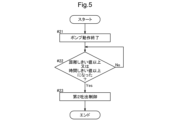
- Flow chart of second discharge control A time chart showing the relationship between the vehicle speed of an electric vehicle and the on/off state of a pump.
- a diagram showing the relationship between oil temperature and the time it takes for the pump to discharge oil.
- the vehicle drive device is mounted on an electric vehicle.
- an embodiment of the vehicle drive device will be described using as an example a three-axis vehicle drive device in which each component is arranged along three virtual parallel axes.
- the direction parallel to each of the above axes is referred to as the "axial direction L". Furthermore, one side in the axial direction L is referred to as the “first axial side L1”, and the other side is referred to as the “second axial side L2". Furthermore, the "radial direction R”, “inner side of the radial direction R”, and “outer side of the radial direction R” may be defined based on each of the above axes.
- driving connection refers to a state in which two rotating elements are connected so as to be able to transmit a driving force, and includes a state in which the two rotating elements are connected so as to rotate integrally, or a state in which the two rotating elements are connected so as to be able to transmit a driving force via one or more transmission members.
- Such transmission members include various members that transmit rotation at the same speed or at a variable speed, such as shafts, gear mechanisms, belts, chains, etc.
- transmission members may also include engagement devices that selectively transmit rotation and driving force, such as friction engagement devices and meshing engagement devices.
- the vehicle drive device 100 includes a rotating electric machine 1 as a driving force source for the wheels W, a power transmission mechanism TM, and a case C that houses the rotating electric machine 1 and the power transmission mechanism TM.
- the rotating electric machine 1 is disposed on the first axis A1.
- the rotating electric machine 1 includes a stator 11 and a rotor 12.
- the stator 11 is fixed to the case C.
- the rotor 12 is disposed radially inward of the stator 11 in the radial direction R.
- the rotor 12 includes a rotor core 120, a rotor shaft 121 disposed radially inward of the rotor core 120 and extending in the axial direction L, and a rotor bearing 122 that supports the rotor shaft 121 rotatably relative to the case C.
- the rotor bearing 122 is configured to support a portion of the rotor shaft 121 on the first axial side L1 relative to the rotor core 120. A portion of the rotor shaft 121 on the second axial side L2 relative to the rotor core 120 is connected to the power transmission mechanism TM.
- the rotor shaft 121 is drivingly connected to the output member 8 so as to rotate constantly in conjunction with the output member 8, which is drivingly connected to the wheel W.
- the rotor shaft 121 is the rotating member that rotates the fastest among the rotating members that make up the power transmission path from the rotating electric machine 1 to the wheels W while the electric vehicle is running.
- the rotor shaft 121 is drivingly connected to the input member 9.
- the input member 9 is provided with an input gear 90.
- the input member 9 and the input gear 90 rotate with the rotation of the rotor shaft 121.
- the input member 9 is disposed on the second axial side L2 relative to the rotating electric machine 1. In other words, the driving force generated by the rotating electric machine 1 is transmitted to the second axial side L2 relative to the rotating electric machine 1.
- the power transmission mechanism TM includes multiple gears that mesh with each other, and is configured to transmit the driving force generated by the rotating electric machine 1 to the wheels W.
- the vehicle drive device 100 includes an output member 8 that is drivingly connected to the wheels W, and the power transmission mechanism TM transmits the driving force between the rotating electric machine 1 and the output member 8.
- the power transmission mechanism TM is configured to transmit the driving force generated by the rotating electric machine 1 on the second axial side L2 of the rotating electric machine 1.
- the power transmission mechanism TM includes a counter gear mechanism 2 and a differential gear mechanism 3.
- the counter gear mechanism 2 and the differential gear mechanism 3 are disposed on the second axial side L2 of the rotating electric machine 1.
- the power transmission mechanism TM may include an engagement element such as a clutch or a brake.
- the counter gear mechanism 2 is arranged on the second axis A2.
- the counter gear mechanism 2 includes a first counter gear 21 and a second counter gear 22.
- the first counter gear 21 and the second counter gear 22 are connected to the same shaft member and are arranged at different positions in the axial direction L on the shaft member.
- the first counter gear 21 is arranged on the first axial side L1 of the second counter gear 22.
- the first counter gear 21 is configured to have a larger diameter than the second counter gear 22.
- the first counter gear 21 meshes with the input gear 90.
- the second counter gear 22 meshes with the differential input gear 30, which will be described later.
- the differential gear mechanism 3 is drivingly connected to the wheels W via an output member 8.
- the differential gear mechanism 3 is drivingly connected to a pair of wheels W, and is configured to distribute the driving force generated by the rotating electric machine 1 to the pair of wheels W.
- the output member 8 is drivingly connected to the wheels W, for example, via a drive shaft (not shown).
- the output member 8 is, for example, the same member as the gears that constitute the differential gear mechanism 3, or is a member that constitutes a connecting shaft that connects the differential gear mechanism and the drive shaft.
- the differential gear mechanism 3 includes a differential input gear 30 and a number of bevel gears that mesh with each other.
- the differential input gear 30 meshes with the second counter gear 22 of the counter gear mechanism 2.
- the driving force input via the differential input gear 30 is distributed and transmitted to the pair of wheels W via each of the pair of output members 8.
- At least some of the multiple gears provided in the power transmission mechanism TM are configured to scoop up the oil in the case C.
- the differential input gear 30 scoops up the oil in the case C.
- the scooped up oil passes through the second supply oil passage N, which will be described later, and is supplied to the rotor bearing 122.
- a power transmission mechanism TM including a plurality of gears meshing with each other and configured to transmit a driving force generated by the rotating electric machine 1 to wheels W;
- the rotor 12 includes a rotor core 120 and a rotor shaft 121.
- the direction in which the rotor shaft 121 extends is defined as an axial direction L, one side in the axial direction L is defined as an axial first side L1, and the other side in the axial direction L is defined as an axial second side L2.
- Rotor bearing 122 is configured to support a portion of rotor shaft 121 on first axial side L ⁇ b>1 with respect to rotor core 120 .
- the portion of the rotor shaft 121 that connects to the power transmission mechanism TM and the portion where the rotor bearing 122 is located are located on opposite sides of each other in the axial direction L. This makes it possible to properly support the rotor shaft 121 with the rotor bearing 122, while properly outputting the driving force of the rotating electric machine 1 that is generated as the rotor shaft 121 rotates to the power transmission mechanism TM.
- the vehicle drive device 100 includes a pump 4 that draws in and discharges oil from a case C, and an oil supply passage P that supplies the oil discharged by the pump 4 to at least the rotor bearing 122.
- the pump 4 is driven by a drive source 4m that is different from the rotating electric machine 1 described above.
- the pump 4 is an electric pump that is driven by an electric motor that serves as the drive source 4m.
- the supply oil passage P is a path through which oil flows from the pump 4 to the rotor bearing 122.
- the supply oil passage P is the first supply oil passage P.
- the first supply oil passage P includes a first oil passage P1, a second oil passage P2, a third oil passage P3, and a fourth oil passage P4.
- the oil discharged from the pump 4 flows in the order of the first oil passage P1, the second oil passage P2, the third oil passage P3, and the fourth oil passage P4, and reaches the rotor bearing 122.
- the oil that reaches the rotor bearing 122 is used to lubricate at least the rotor bearing 122.
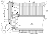
- the case C has a wall portion Cw (here, the end wall portion of the axial first side L1) that covers the rotating electric machine 1 from the axial first side L1 and extends in the radial direction R.
- the first oil passage P1 is provided in the wall portion Cw of the case C.
- the second oil passage P2 is connected to the first oil passage P1.
- the second oil passage P2 includes an opening that opens to the surface of the wall portion Cw on the second axial side L2 and the internal space of the rotor shaft 121 (intra-shaft space Si).
- the third oil passage P3 is connected to the second oil passage P2.
- the third oil passage P3 penetrates a part of the rotor shaft 121 in the radial direction R.
- the fourth oil passage P4 is connected to the third oil passage P3 and is connected to the rotor bearing 122.
- the fourth oil passage P4 includes the external space of the rotor shaft 121 (off-shaft space So) and a path formed along the wall portion Cw from the off-shaft space So to the rotor bearing 122.
- the oil discharged from the pump 4 reaches the rotor bearing 122 in the following order (1) to (5).
- the oil discharged from the pump 4 flows through the first oil passage P1.
- Oil flows from the first oil passage P1 to the second oil passage P2.
- the oil in the second oil passage P2 is at least temporarily stored in the shaft space Si.
- the oil stored in the in-shaft space Si is injected into the fourth oil passage P4 (the off-shaft space So) via the third oil passage P3 by the action of centrifugal force accompanying the rotation of the rotor shaft 121.
- the oil injected into the off-axis space So travels along the wall portion Cw of the case C and reaches the rotor bearing 122.
- the oil discharged from the pump 4 may reach the rotor bearing 122 regardless of the above order (1) to (5).
- the oil stored in the shaft space Si may reach the rotor bearing 122 directly.
- some oil flows directly through the first oil passage P1 toward the outside in the radial direction R.
- This type of oil is supplied to the rotating electric machine 1 from the outside in the radial direction R, and is used to cool the rotating electric machine 1.
- the oil may reach the fourth oil passage P4, flow through the fourth oil passage P4, and reach the rotor bearing 122.
- the pump 4 according to this embodiment can be used not only for cooling the rotating electric machine 1, but also for lubricating the rotor bearing 122 supporting the rotor shaft 121 of the rotating electric machine 1.
- the rotor bearing 122 is configured to support the end of the rotor shaft 121 on the first axial side L1. Therefore, the oil discharged from the pump 4 is mainly supplied to the portion of the rotating electric machine 1 on the first axial side L1.
- the supply of oil to the portion of the rotating electric machine 1 on the second axial side L2, i.e., the power transmission mechanism TM, is performed by scooping up the oil in the case C by the rotating members constituting the power transmission mechanism TM (for example, gears such as the differential input gear 30).
- the places to which the oil is supplied by scooping up the oil include bearings other than the rotor bearing 122 (hereinafter referred to as "target bearings").
- the target bearing includes, for example, a bearing that rotatably supports a portion of the rotor shaft 121 that is located on the second axial side L2 relative to the rotor core 120.
- the target bearing includes a bearing that rotatably supports the output member 8 on the first axial side L1.
- the vehicle drive device 100 includes a second oil supply passage N that supplies oil scooped up by a gear (e.g., differential input gear 30) included in the power transmission mechanism TM to the rotor bearing 122.
- a gear e.g., differential input gear 30
- the oil scooped up by the gear of the power transmission mechanism TM on the second axial side L2 from the rotating electric machine 1 passes outside in the radial direction R from the rotating electric machine 1 (see FIG. 1), reaches the first axial side L1 from the rotating electric machine 1, and reaches the rotor bearing 122 along the inner wall of the case C that faces the rotating electric machine 1 on the first axial side L1 (see FIG. 2).
- the second oil supply passage N is formed along this flow of oil.
- the second oil supply passage N includes at least one of an opening penetrating the case C, a closed or open path formed in the wall of the case C, and a path formed by a pipe that is a separate member from the case C. It is also preferable that the second oil supply passage N includes a catch tank that temporarily stores oil scooped up by the gears of the power transmission mechanism TM.
- the supply oil passage P is a first supply oil passage P, At least some of the gears are configured to scoop up oil in the case C; A second oil supply passage N is provided to supply the oil scooped up by the gear to the rotor bearing 122.
- the vehicle drive device 100 is equipped with a control device 5 that controls the pump 4.
- the control device 5 is equipped with an arithmetic processing device such as a CPU (Central Processing Unit), as well as a storage device that can be referenced by the arithmetic processing device, such as a RAM (Random Access Memory) or a ROM (Read Only Memory).
- arithmetic processing device such as a CPU (Central Processing Unit)
- a storage device that can be referenced by the arithmetic processing device, such as a RAM (Random Access Memory) or a ROM (Read Only Memory).
- Each function of the control device 5 (the functions of each functional unit described below) is realized by software (programs) stored in the storage device or hardware such as a separately provided arithmetic circuit, or both.
- the arithmetic processing device equipped in the control device 5 operates as a computer that executes each program.
- An electric vehicle is equipped with various sensors, and the control device 5 is configured to be able to acquire detection information from the various sensors.
- Functional units (see FIG. 3) provided in the control device 5 for acquiring various information acquire necessary information based on the detection information from the sensors.
- the multiple functional units (51-55) of the control device 5 are at least conceptually distinct as shown in FIG. 3, and do not necessarily need to be physically distinct.
- the multiple functional units of the control device 5 do not need to be realized by common hardware, and may be realized by being divided into multiple pieces of hardware that can communicate with each other.
- the control device 5 controls the operation of the pump 4 by controlling the driving of the drive source 4m.
- the control device 5 includes a power supply state acquisition unit 51 that acquires information indicating the on/off state of the main power supply (e.g., a main switch or an ignition switch) of the electric vehicle, and a vehicle speed acquisition unit 52 that acquires information indicating the vehicle speed of the electric vehicle.
- the vehicle speed acquisition unit 52 may be configured to acquire information regarding the vehicle speed itself, or may be configured to acquire information regarding an index that changes depending on the vehicle speed (e.g., the rotational speed of the output member 8 or a member that rotates integrally with the output member 8).
- the control device 5 further includes a mileage acquisition unit 53 that acquires information indicating the mileage of the electric vehicle, and an elapsed time acquisition unit 54 that acquires information indicating the elapsed time.
- the elapsed time acquisition unit 54 is a functional unit that acquires information regarding the time that has elapsed since the occurrence or end of an event, and in this example, as described below, is configured to acquire information regarding the elapsed time since the pump 4 has stopped operating.
- the control device 5 further includes an oil temperature acquisition unit 55 that acquires information indicating the temperature of the oil in the case C.
- the control device 5 is configured to be able to execute the first discharge control and the second discharge control.
- the first discharge control is executed on the condition that the first discharge condition is satisfied.
- the second discharge control is executed on the condition that the second discharge condition is satisfied.
- "executing as a condition” includes both a configuration in which the control is executed when the condition is satisfied, and a configuration in which the control is executed when other conditions are satisfied in addition to the condition.
- the first discharge condition for performing the first discharge control is that the main power supply has been switched from off to on, and that the vehicle speed has reached or exceeded a predetermined vehicle speed threshold value Vx.
- control device 5 determines whether the main power supply has changed from off to on (step #11). This determination is made based on the information acquired by the power supply status acquisition unit 51.
- the control device 5 determines whether the vehicle speed of the electric vehicle has reached the vehicle speed threshold value Vx (step #12). This determination is made based on the information acquired by the vehicle speed acquisition unit 52.
- the vehicle speed threshold value Vx is set based on the vehicle speed corresponding to the rotation speed of the rotor bearing 122.
- the vehicle speed threshold value Vx is a value that is set in advance by experiments, etc. For example, the vehicle speed threshold value Vx may be set to a value (speed) at which it can be determined that the electric vehicle has accelerated from a stopped state or a creeping state due to an artificial accelerator operation, etc.
- the vehicle speed threshold value Vx is set in the range of 10 kilometers per hour to 20 kilometers per hour. Preferably, the vehicle speed threshold value Vx is set to 15 kilometers per hour. However, the vehicle speed threshold value Vx may change depending on the performance of each component of the vehicle drive device 100, the performance of the oil, or the environment in which the electric vehicle is used.
- control device 5 determines that the vehicle speed of the electric vehicle has reached the vehicle speed threshold value Vx (step #12: Yes), it executes the first discharge control (step #13).
- the control device 5 operates the pump 4 for a predetermined first discharge time T1 (see also FIG. 6).
- T1 a predetermined first discharge time
- FIG. 4 assumes that the first discharge control is executed when the first discharge condition is satisfied, but in this embodiment, as described below, operation of the pump 4 is prohibited when the oil temperature is below the oil temperature threshold Ox. Therefore, in this embodiment, the first discharge control is executed when, in addition to satisfying the first discharge condition, the condition that the oil temperature is equal to or higher than the oil temperature threshold Ox is satisfied.
- the second discharge condition for performing the second discharge control is at least one of the following: the travel distance after the end of the previous operation of the pump 4 is equal to or greater than a predetermined distance threshold, and the elapsed time is equal to or greater than a predetermined time threshold Tx. In other words, the second discharge control is executed when at least one of these conditions is satisfied. Note that the "previous operation of the pump 4" does not include the operation of the pump 4 before the main power was turned on. In this example, the second discharge condition is that the elapsed time (the time elapsed since the end of the operation of the pump 4) is equal to or greater than the predetermined time threshold Tx.
- the control device 5 judges whether the travel distance since the end of the operation of the pump 4 is equal to or greater than a predetermined distance threshold, or whether the elapsed time since the end of the operation of the pump 4 is equal to or greater than a time threshold Tx (step #22). In this example, the control device 5 judges whether the elapsed time since the end of the operation of the pump 4 is equal to or greater than the time threshold Tx. This judgment is made based on the information acquired by the elapsed time acquisition unit 54.
- the time threshold Tx is a value that is set in advance by experiments, etc.
- the time threshold Tx is set to a value (time) that will not cause any problems for the rotor bearing 122 to be lubricated even if oil is not supplied from the pump 4.
- the time threshold Tx is set in the range of 8 hours to 12 hours.
- the time threshold Tx is set to 10 hours.
- the time threshold Tx may change depending on the performance of each component of the vehicle drive device 100, the performance of the oil, or the environment in which the electric vehicle is used.
- control device 5 determines that the time elapsed since the pump 4 stopped operating is equal to or greater than the time threshold value Tx (step #22: Yes), it executes the second discharge control (step #23).
- the control device 5 operates the pump 4 for a predetermined second discharge time T2 (see also FIG. 6).
- T2 a predetermined second discharge time
- FIG. 5 assumes that the second discharge control is executed when the second discharge condition is satisfied, but in this embodiment, as described below, the operation of the pump 4 is prohibited when the oil temperature is below the oil temperature threshold Ox. Therefore, in this embodiment, the second discharge control is executed when, in addition to satisfying the second discharge condition, the condition that the oil temperature is equal to or higher than the oil temperature threshold Ox is satisfied.
- the second discharge control is repeatedly executed by satisfying the second discharge condition while the main power supply is switched from on to off.
- the first discharge of oil after the main power supply is switched on is performed by the first discharge control
- the second and subsequent discharges of oil are performed by the second discharge control.
- the vehicle drive device 100 has A rotating electric machine 1 including a rotor 12 as a driving force source for a wheel W; a case C that accommodates the rotating electric machine 1 and oil; a pump 4 driven by a drive source 4m different from the rotary electric machine 1 and configured to suck and discharge oil from within a case C; an oil supply passage P for supplying the oil discharged by the pump 4 to at least a rotor bearing 122 that rotatably supports the rotor 12; A control device 5 for controlling the pump 4; Equipped with The control device 5 includes a power supply state acquisition unit 51 that acquires information indicating an on/off state of a main power supply (not shown) of the electric vehicle, and a vehicle speed acquisition unit 52 that acquires information indicating a vehicle speed of the electric vehicle. The control device 5 executes a first discharge control to operate the pump 4 for a predetermined first discharge time T1, on the condition that the main power supply has been turned from off to on and the vehicle speed has become equal to or greater than a predetermined
- the conditions for operating the pump 4 by the first discharge control include not only the main power supply being switched from off to on, but also the vehicle speed being equal to or higher than the vehicle speed threshold Vx.
- the pump 4 does not necessarily operate when the power supply is turned on, but does not operate unless the vehicle speed is relatively high. Therefore, the operating time of the pump 4 can be kept short. This reduces the energy consumption caused by operating the pump 4, making it easier to improve the energy efficiency of the vehicle drive device 100.
- the load on the pump 4 can be kept low, reducing the need to use a highly durable pump, and making it easier to keep the cost of the pump 4 low while ensuring the required product life.
- the control device 5 further includes a travel distance acquisition unit 53 that acquires information indicating a travel distance of the electric vehicle, and an elapsed time acquisition unit 54 that acquires information indicating an elapsed time,
- the control device 5 executes a second discharge control to operate the pump 4 for a predetermined second discharge time T2 under at least one of the conditions that the traveled distance after the end of the previous operation of the pump 4 is equal to or greater than a predetermined distance threshold value and that the elapsed time is equal to or greater than a predetermined time threshold value Tx.
- the pump 4 is not operated all the time, but is operated only for a predetermined time when certain conditions are met, so that the operating time of the pump 4 can be kept short.
- Figure 6 is a time chart showing the relationship between the vehicle speed of the electric vehicle and the on/off state of the pump.
- the control device 5 executes the first discharge control and operates the pump 4 for the first discharge time T1.
- the control device 5 stops the pump 4.
- the control device 5 executes the second discharge control, operates the pump 4 again, and continues this operation for the second discharge time T2.
- the first discharge time T1 is set based on the time it takes for the oil discharged from the pump 4 to reach the rotor bearing 122 via the first oil supply passage P. In this example, the first discharge time T1 is set longer than the second discharge time T2.
- the first discharge control in which oil is discharged from the pump 4 only after the main power supply of the electric vehicle is turned on, the oil temperature is often lower than when the electric vehicle is running, and the viscosity of oil increases when the temperature is low.
- the first discharge time T1 i.e., the operating time of the pump 4 in the first discharge control
- the second discharge time T2 it is easier to ensure that the oil reaches the rotor bearing 122 appropriately even when the viscosity of the oil is relatively high.
- the second discharge time T2 is set shorter than the first discharge time T1. This makes it possible to reduce the operating time of the pump 4. Therefore, it is possible to reduce the energy consumption caused by operating the pump 4, thereby increasing the energy efficiency of the vehicle drive device 100, and to reduce the load on the pump 4, thereby ensuring a long product life.
- the vehicle speed threshold value Vx is set based on a vehicle speed corresponding to the rotation speed of the rotor bearing 122
- the first discharge time T1 is set based on the time it takes for the oil discharged from the pump 4 to reach the rotor bearing 122 via the oil supply passage P.
- This configuration allows oil to be appropriately supplied to the rotor bearing 122 under the required conditions. Therefore, insufficient lubrication of the rotor bearing 122 can be avoided.
- Figure 7 shows the relationship between oil temperature and the time it takes for the pump to discharge oil.
- the lower the temperature of the oil the higher its viscosity becomes, and the longer it takes for the oil to reach the rotor bearing 122 from the pump 4. Furthermore, if the temperature of the oil is too low, the oil becomes extremely viscous. In this case, the load on the pump 4 becomes excessive, which shortens the life of the pump 4.
- the control device 5 further includes an oil temperature acquisition unit 55 that acquires information indicating the temperature of the oil in the case C (see FIG. 3 ).
- the control device 5 is When the oil temperature is equal to or higher than a predetermined oil temperature threshold value Ox, the first discharge time T1 is set longer as the oil temperature decreases, When the oil temperature is below the oil temperature threshold value Ox, the operation of the pump 4 is inhibited.
- the oil temperature threshold Ox is determined based on the viscosity of the oil. That is, the oil temperature threshold Ox is set to a temperature at which the viscosity of the oil reaches a value that may lead to failure of the pump 4. Although it depends on the performance of the oil, in the case of general oils used in vehicle drive systems (e.g., ATF: Automatic transmission fluid), the oil temperature threshold Ox is set in the range of minus 20 degrees to minus 30 degrees. For example, the oil temperature threshold Ox may be set to minus 25 degrees.
- the first discharge time T1 is set longer as the oil temperature decreases, so that even oil with a low temperature and high viscosity can be properly allowed to reach the rotor bearing 122.
- oil that is extremely viscous due to being too low in temperature places an excessive load on the pump 4 that discharges it, and is likely to be a factor in shortening the life of the pump 4.
- FIG. 7 illustrates a case in which the first discharge time T1 is set continuously longer as the oil temperature decreases, but the first discharge time T1 may be set to be longer in stages as the oil temperature decreases.
- the second discharge time T2 was set shorter than the first discharge time T1.
- the second discharge time T2 may be set longer than the first discharge time T1, or may be set the same as the first discharge time T1.
- the second discharge time T2 may be set longer as the oil temperature decreases.
- the control device 5 executes the first discharge control on condition that the first discharge condition is satisfied, and executes the second discharge control on condition that the second discharge condition is satisfied, in order to lubricate the rotor bearing 122.
- the control device 5 may also operate the pump 4 when other conditions different from the above conditions are satisfied.
- the control device 5 may operate the pump 4 when a rotating electric machine cooling condition, which is a condition for cooling the rotating electric machine 1, is satisfied.
- the vehicle drive device 100 may be provided with a sensor that detects the temperature of the rotating electric machine 1. For example, when the temperature of the rotating electric machine 1 becomes equal to or higher than a predetermined temperature threshold, it is determined that the rotating electric machine cooling condition is satisfied.
- the control device 5 executes the third discharge control, which operates the pump 4 for a predetermined third discharge time, on condition that the rotating electric machine cooling condition is satisfied.
- the second discharge condition is that the elapsed time (the time elapsed since the operation of the pump 4 ended) is equal to or greater than a predetermined time threshold value Tx.
- the second discharge condition may be that the traveled distance after the previous operation of the pump 4 ended is equal to or greater than a predetermined distance threshold value.
- the second discharge condition may be that both the elapsed time is equal to or greater than the time threshold value Tx and the traveled distance is equal to or greater than the distance threshold value are satisfied.
- a three-axis vehicle drive device 100 is illustrated.
- the invention is not limited to this example, and the vehicle drive device 100 may have a single-axis configuration in which each component is arranged coaxially.
- the power transmission mechanism TM may include a planetary gear reduction mechanism.
- the conditions for operating the pump (4) by the first discharge control include not only the main power supply being switched from off to on, but also the vehicle speed being equal to or higher than the vehicle speed threshold (Vx).
- the pump (4) does not necessarily operate when the power supply is started, but does not operate unless the vehicle speed is relatively high. Therefore, the operating time of the pump (4) can be reduced. This reduces the energy consumption caused by operating the pump (4), making it easier to improve the energy efficiency of the vehicle drive device (100).
- the load on the pump (4) can be reduced, reducing the need to use a highly durable pump, and making it easier to keep the cost of the pump (4) low while ensuring the required product life.
- the control device (5) further includes a mileage acquisition unit (53) that acquires information indicating a mileage of the electric vehicle, and an elapsed time acquisition unit (54) that acquires information indicating an elapsed time, It is preferable that the control device (5) executes a second discharge control to operate the pump (4) for a predetermined second discharge time (T2) under at least one of the conditions that the traveling distance after the end of the previous operation of the pump (4) is equal to or greater than a predetermined distance threshold and that the elapsed time is equal to or greater than a predetermined time threshold (Tx).
- T2 predetermined second discharge time
- the pump (4) is not operated all the time, but is operated only for a predetermined time when certain conditions are met, so that the operating time of the pump (4) can be kept short.
- the control device (5) further includes an oil temperature acquisition unit (55) that acquires information indicating the temperature of the oil in the case (C), The control device (5)
- an oil temperature acquisition unit (55) that acquires information indicating the temperature of the oil in the case (C)
- the control device (5) When the oil temperature is equal to or higher than a predetermined oil temperature threshold value (Ox), the first discharge time (T1) is set to be longer as the oil temperature decreases.
- Ox oil temperature threshold
- the first discharge time (T1) is set longer as the oil temperature decreases, so that even oil with a low temperature and high viscosity can be made to reach the rotor bearing (122) appropriately.
- oil that is extremely viscous because its temperature is too low can place an excessive load on the pump (4) that discharges it, which can easily shorten the life of the pump (4).
- the oil temperature is below the oil temperature threshold (Ox)
- the operation of the pump (4) is prohibited, so such adverse effects can be avoided.
- the vehicle speed threshold (Vx) is set based on a vehicle speed corresponding to the rotation speed of the rotor bearing (122); It is preferable that the first discharge time (T1) is set based on the time it takes for the oil discharged from the pump (4) to reach the rotor bearing (122) via the oil supply passage (P).
- the rotor (12) includes a rotor core (120) and a rotor shaft (121).
- the direction in which the rotor shaft (121) extends is defined as the axial direction (L), one side in the axial direction (L) is defined as the axial first side (L1), and the other side in the axial direction (L) is defined as the axial second side (L2), A portion of the rotor shaft (121) on a second axial side (L2) with respect to the rotor core (120) is connected to a power transmission mechanism (TM), It is preferable that the rotor bearing (122) is configured to support a portion of the rotor shaft (121) on a first axial side (L1) with respect to the rotor core (120).
- the connecting portion of the rotor shaft (121) with the power transmission mechanism (TM) and the portion where the rotor bearing (122) is arranged are arranged on opposite sides of each other in the axial direction (L). This makes it possible to properly support the rotor shaft (121) with the rotor bearing (122) while properly outputting the driving force of the rotating electric machine (1) generated as the rotor shaft (121) rotates to the power transmission mechanism (TM).
- the supply oil passage (P) is a first supply oil passage (P), At least some of the gears are configured to scoop up oil in the case (C); It is preferable to provide a second oil supply passage (N) for supplying the oil scooped up by the gear to the rotor bearing (122).
- the technology disclosed herein can be used in vehicle drive devices mounted on electric vehicles.
Landscapes
- Engineering & Computer Science (AREA)
- General Engineering & Computer Science (AREA)
- Mechanical Engineering (AREA)
- Power Engineering (AREA)
- Transportation (AREA)
- Electric Propulsion And Braking For Vehicles (AREA)
- General Details Of Gearings (AREA)
Abstract
Description
車輪の駆動力源としてのロータを備えた回転電機と、
前記回転電機及び油を収容するケースと、
前記回転電機とは異なる駆動源により駆動され、前記ケース内の油を吸引して吐出するポンプと、
前記ポンプが吐出した油を少なくとも前記ロータを回転自在に支持するロータ軸受に供給する供給油路と、
前記ポンプを制御する制御装置と、
を備え、
前記制御装置は、前記電動車両の主電源のオンオフ状態を示す情報を取得する電源状態取得部と、前記電動車両の車速を示す情報を取得する車速取得部と、を備え、
前記制御装置は、前記主電源がオフからオンになったこと、及び、前記車速が予め定められた車速しきい値以上となったことを条件として、前記ポンプを予め定められた第1吐出時間動作させる第1吐出制御を実行する。
互いに噛み合う複数のギヤを備え、回転電機1が発生した駆動力を車輪Wに伝達する動力伝達機構TMが設けられ、
ロータ12は、ロータコア120とロータ軸121とを備え、
ロータ軸121が延びる方向を軸方向Lとし、軸方向Lにおける一方側を軸方向第1側L1とし、軸方向Lにおける他方側を軸方向第2側L2として、
ロータ軸121におけるロータコア120に対して軸方向第2側L2の部分が、動力伝達機構TMに連結され、
ロータ軸受122は、ロータ軸121におけるロータコア120に対して軸方向第1側L1の部分を支持するように構成されている。
(1)ポンプ4から吐出された油は、第1油路P1を流れる。
(2)油は、第1油路P1から第2油路P2へ流れる。
(3)第2油路P2の油は、軸内空間Siに少なくとも一時的に貯留される。
(4)軸内空間Siに貯留された油は、ロータ軸121の回転に伴う遠心力の作用によって、第3油路P3を介して第4油路P4(軸外空間Sо)に噴射される。
(5)軸外空間Sоに噴射された油は、ケースCの壁部Cwを伝ってロータ軸受122に到達する。
供給油路Pが、第1供給油路Pであり、
複数のギヤの少なくとも一部が、ケースC内の油を掻き上げるように構成され、
ギヤが掻き上げた油をロータ軸受122に供給する第2供給油路Nを備える。
車輪Wの駆動力源としてのロータ12を備えた回転電機1と、
回転電機1及び油を収容するケースCと、
回転電機1とは異なる駆動源4mにより駆動され、ケースC内の油を吸引して吐出するポンプ4と、
ポンプ4が吐出した油を少なくともロータ12を回転自在に支持するロータ軸受122に供給する供給油路Pと、
ポンプ4を制御する制御装置5と、
を備え、
制御装置5は、電動車両の主電源(不図示)のオンオフ状態を示す情報を取得する電源状態取得部51と、電動車両の車速を示す情報を取得する車速取得部52と、を備え、
制御装置5は、前記主電源がオフからオンになったこと、及び、前記車速が予め定められた車速しきい値Vx以上となったことを条件として、前記ポンプ4を予め定められた第1吐出時間T1動作させる第1吐出制御を実行する。
制御装置5は、電動車両の走行距離を示す情報を取得する走行距離取得部53と、経過時間を示す情報を取得する経過時間取得部54と、を更に備え、
制御装置5は、前回のポンプ4の動作の終了後、走行距離が予め定められた距離しきい値以上となったこと、及び、経過時間が予め定められた時間しきい値Tx以上となったこと、の少なくとも一方を条件として、ポンプ4を予め定められた第2吐出時間T2動作させる第2吐出制御を実行する。
車速しきい値Vxは、ロータ軸受122の回転速度に対応する車速に基づいて設定され、
第1吐出時間T1は、ポンプ4から吐出した油が供給油路Pを介してロータ軸受122に到達するまでの時間に基づいて設定されている。
制御装置5は、ケースC内の油の温度を示す情報を取得する油温取得部55を更に備え(図3参照)、
制御装置5は、
油の温度が予め定められた油温しきい値Оx以上である場合には、油の温度が低くなるに従って第1吐出時間T1を長く設定し、
油の温度が油温しきい値Оx未満である場合には、ポンプ4の動作を禁止する。
次に、その他の実施形態について説明する。
上記において説明した車両用駆動装置に係る実施形態のまとめを以下に記載する。
車輪(W)の駆動力源としてのロータ(12)を備えた回転電機(1)と、
回転電機(1)及び油を収容するケース(C)と、
回転電機(1)とは異なる駆動源(4m)により駆動され、ケース(C)内の油を吸引して吐出するポンプ(4)と、
ポンプ(4)が吐出した油を少なくともロータ(12)を回転自在に支持するロータ軸受(122)に供給する供給油路(P)と、
ポンプ(4)を制御する制御装置(5)と、
を備え、
制御装置(5)は、電動車両の主電源のオンオフ状態を示す情報を取得する電源状態取得部(51)と、電動車両の車速を示す情報を取得する車速取得部(52)と、を備え、
制御装置(5)は、前記主電源がオフからオンになったこと、及び、前記車速が予め定められた車速しきい値(Vx)以上となったことを条件として、前記ポンプ(4)を予め定められた第1吐出時間(T1)動作させる第1吐出制御を実行する。
制御装置(5)は、前回のポンプ(4)の動作の終了後、走行距離が予め定められた距離しきい値以上となったこと、及び、経過時間が予め定められた時間しきい値(Tx)以上となったこと、の少なくとも一方を条件として、ポンプ(4)を予め定められた第2吐出時間(T2)動作させる第2吐出制御を実行する、と好適である。
制御装置(5)は、
油の温度が予め定められた油温しきい値(Оx)以上である場合には、油の温度が低くなるに従って第1吐出時間(T1)を長く設定し、
油の温度が油温しきい値(Оx)未満である場合には、ポンプ(4)の動作を禁止する、と好適である。
第1吐出時間(T1)は、ポンプ(4)から吐出した油が供給油路(P)を介してロータ軸受(122)に到達するまでの時間に基づいて設定されている、と好適である。
ロータ(12)は、ロータコア(120)とロータ軸(121)とを備え、
ロータ軸(121)が延びる方向を軸方向(L)とし、軸方向(L)における一方側を軸方向第1側(L1)とし、軸方向(L)における他方側を軸方向第2側(L2)として、
ロータ軸(121)におけるロータコア(120)に対して軸方向第2側(L2)の部分が、動力伝達機構(TM)に連結され、
ロータ軸受(122)は、ロータ軸(121)におけるロータコア(120)に対して軸方向第1側(L1)の部分を支持するように構成されている、と好適である。
複数のギヤの少なくとも一部が、ケース(C)内の油を掻き上げるように構成され、
ギヤが掻き上げた油をロータ軸受(122)に供給する第2供給油路(N)を備える、と好適である。
Claims (6)
- 電動車両に搭載される車両用駆動装置であって、
車輪の駆動力源としてのロータを備えた回転電機と、
前記回転電機及び油を収容するケースと、
前記回転電機とは異なる駆動源により駆動され、前記ケース内の油を吸引して吐出するポンプと、
前記ポンプが吐出した油を少なくとも前記ロータを回転自在に支持するロータ軸受に供給する供給油路と、
前記ポンプを制御する制御装置と、
を備え、
前記制御装置は、前記電動車両の主電源のオンオフ状態を示す情報を取得する電源状態取得部と、前記電動車両の車速を示す情報を取得する車速取得部と、を備え、
前記制御装置は、前記主電源がオフからオンになったこと、及び、前記車速が予め定められた車速しきい値以上となったことを条件として、前記ポンプを予め定められた第1吐出時間動作させる第1吐出制御を実行する、車両用駆動装置。 - 前記制御装置は、前記電動車両の走行距離を示す情報を取得する走行距離取得部と、経過時間を示す情報を取得する経過時間取得部と、を更に備え、
前記制御装置は、前回の前記ポンプの動作の終了後、前記走行距離が予め定められた距離しきい値以上となったこと、及び、前記経過時間が予め定められた時間しきい値以上となったこと、の少なくとも一方を条件として、前記ポンプを予め定められた第2吐出時間動作させる第2吐出制御を実行する、請求項1に記載の車両用駆動装置。 - 前記制御装置は、前記ケース内の油の温度を示す情報を取得する油温取得部を更に備え、
前記制御装置は、
油の温度が予め定められた油温しきい値以上である場合には、油の温度が低くなるに従って前記第1吐出時間を長く設定し、
油の温度が前記油温しきい値未満である場合には、前記ポンプの動作を禁止する、請求項1に記載の車両用駆動装置。 - 前記車速しきい値は、前記ロータ軸受の回転速度に対応する前記車速に基づいて設定され、
前記第1吐出時間は、前記ポンプから吐出した油が前記供給油路を介して前記ロータ軸受に到達するまでの時間に基づいて設定されている、請求項1に記載の車両用駆動装置。 - 互いに噛み合う複数のギヤを備え、前記回転電機が発生した駆動力を前記車輪に伝達する動力伝達機構が設けられ、
前記ロータは、ロータコアとロータ軸とを備え、
前記ロータ軸が延びる方向を軸方向とし、前記軸方向における一方側を軸方向第1側とし、前記軸方向における他方側を軸方向第2側として、
前記ロータ軸における前記ロータコアに対して前記軸方向第2側の部分が、前記動力伝達機構に連結され、
前記ロータ軸受は、前記ロータ軸における前記ロータコアに対して前記軸方向第1側の部分を支持するように構成されている、請求項1から4のいずれか一項に記載の車両用駆動装置。 - 前記供給油路が、第1供給油路であり、
複数の前記ギヤの少なくとも一部が、前記ケース内の油を掻き上げるように構成され、
前記ギヤが掻き上げた油を前記ロータ軸受に供給する第2供給油路を備える、請求項5に記載の車両用駆動装置。
Priority Applications (3)
| Application Number | Priority Date | Filing Date | Title |
|---|---|---|---|
| CN202480007192.0A CN120530273A (zh) | 2023-03-30 | 2024-01-26 | 车辆用驱动装置 |
| EP24778625.4A EP4624782A4 (en) | 2023-03-30 | 2024-01-26 | VEHICLE TRAINING DEVICE |
| JP2025509811A JP7800769B2 (ja) | 2023-03-30 | 2024-01-26 | 車両用駆動装置 |
Applications Claiming Priority (2)
| Application Number | Priority Date | Filing Date | Title |
|---|---|---|---|
| JP2023055351 | 2023-03-30 | ||
| JP2023-055351 | 2023-03-30 |
Publications (1)
| Publication Number | Publication Date |
|---|---|
| WO2024202479A1 true WO2024202479A1 (ja) | 2024-10-03 |
Family
ID=92903959
Family Applications (1)
| Application Number | Title | Priority Date | Filing Date |
|---|---|---|---|
| PCT/JP2024/002370 Ceased WO2024202479A1 (ja) | 2023-03-30 | 2024-01-26 | 車両用駆動装置 |
Country Status (4)
| Country | Link |
|---|---|
| EP (1) | EP4624782A4 (ja) |
| JP (1) | JP7800769B2 (ja) |
| CN (1) | CN120530273A (ja) |
| WO (1) | WO2024202479A1 (ja) |
Citations (6)
| Publication number | Priority date | Publication date | Assignee | Title |
|---|---|---|---|---|
| JPH04185262A (ja) * | 1990-11-20 | 1992-07-02 | Aisin Aw Co Ltd | ホイールモータの潤滑装置 |
| JP2011259590A (ja) * | 2010-06-08 | 2011-12-22 | Aisin Aw Co Ltd | 車両用駆動装置 |
| JP2016208722A (ja) * | 2015-04-24 | 2016-12-08 | 日産自動車株式会社 | 駆動ユニット |
| JP2018057183A (ja) * | 2016-09-29 | 2018-04-05 | トヨタ自動車株式会社 | 回転電機システム |
| WO2020067259A1 (ja) * | 2018-09-28 | 2020-04-02 | 日本電産株式会社 | 駆動装置 |
| JP2022154736A (ja) | 2021-03-30 | 2022-10-13 | 日本電産株式会社 | 駆動装置、駆動装置の制御方法 |
Family Cites Families (1)
| Publication number | Priority date | Publication date | Assignee | Title |
|---|---|---|---|---|
| JP6194911B2 (ja) * | 2015-03-13 | 2017-09-13 | トヨタ自動車株式会社 | ハイブリッド車両の潤滑構造 |
-
2024
- 2024-01-26 CN CN202480007192.0A patent/CN120530273A/zh active Pending
- 2024-01-26 WO PCT/JP2024/002370 patent/WO2024202479A1/ja not_active Ceased
- 2024-01-26 JP JP2025509811A patent/JP7800769B2/ja active Active
- 2024-01-26 EP EP24778625.4A patent/EP4624782A4/en active Pending
Patent Citations (6)
| Publication number | Priority date | Publication date | Assignee | Title |
|---|---|---|---|---|
| JPH04185262A (ja) * | 1990-11-20 | 1992-07-02 | Aisin Aw Co Ltd | ホイールモータの潤滑装置 |
| JP2011259590A (ja) * | 2010-06-08 | 2011-12-22 | Aisin Aw Co Ltd | 車両用駆動装置 |
| JP2016208722A (ja) * | 2015-04-24 | 2016-12-08 | 日産自動車株式会社 | 駆動ユニット |
| JP2018057183A (ja) * | 2016-09-29 | 2018-04-05 | トヨタ自動車株式会社 | 回転電機システム |
| WO2020067259A1 (ja) * | 2018-09-28 | 2020-04-02 | 日本電産株式会社 | 駆動装置 |
| JP2022154736A (ja) | 2021-03-30 | 2022-10-13 | 日本電産株式会社 | 駆動装置、駆動装置の制御方法 |
Non-Patent Citations (1)
| Title |
|---|
| See also references of EP4624782A1 |
Also Published As
| Publication number | Publication date |
|---|---|
| JP7800769B2 (ja) | 2026-01-16 |
| JPWO2024202479A1 (ja) | 2024-10-03 |
| CN120530273A (zh) | 2025-08-22 |
| EP4624782A4 (en) | 2026-03-25 |
| EP4624782A1 (en) | 2025-10-01 |
Similar Documents
| Publication | Publication Date | Title |
|---|---|---|
| US10337603B2 (en) | Lubricating structure for hybrid vehicle | |
| JP6664506B2 (ja) | 車両用駆動装置 | |
| EP2698565B1 (en) | Lubrication control device for in-wheel motor unit for vehicle | |
| US11353103B2 (en) | Control device for vehicle oil supply device | |
| US11318834B2 (en) | Vehicle driving apparatus | |
| JP4218129B2 (ja) | 油圧発生装置及びそれを用いたハイブリッド車輌 | |
| CN103890460B (zh) | 用于将油从储备容器输送至机动车的传动系统的输送装置 | |
| US9718461B2 (en) | Control system for hybrid vehicle | |
| US20030127262A1 (en) | Motor vehicle drive arrangement | |
| US20110297258A1 (en) | Hydraulic control circuit of vehicular power transmission apparatus | |
| US8739931B2 (en) | Lubricating structure of differential gear unit | |
| EP2627529A2 (en) | Electric vehicle drive system | |
| JP7452536B2 (ja) | 駆動装置、および車両駆動システム | |
| JP6933775B2 (ja) | 車両用パワーユニット | |
| CN112344003B (zh) | 动力传递装置 | |
| KR20160088240A (ko) | 하이브리드 차의 구동 제어 시스템 | |
| JP2016065617A (ja) | インホイールモータ駆動装置の潤滑装置 | |
| WO2020213507A1 (ja) | 駆動装置 | |
| JP5370178B2 (ja) | 車輪独立駆動ユニット | |
| JP7800769B2 (ja) | 車両用駆動装置 | |
| US20180266487A1 (en) | Structure with bearing and bearing | |
| JP2012241820A (ja) | 電気自動車用減速差動装置 | |
| JP6725464B2 (ja) | 車両駆動装置 | |
| JP2007055528A (ja) | オイル供給装置 | |
| CN213575465U (zh) | 变速箱 |
Legal Events
| Date | Code | Title | Description |
|---|---|---|---|
| 121 | Ep: the epo has been informed by wipo that ep was designated in this application |
Ref document number: 24778625 Country of ref document: EP Kind code of ref document: A1 |
|
| WWE | Wipo information: entry into national phase |
Ref document number: 2025509811 Country of ref document: JP |
|
| WWE | Wipo information: entry into national phase |
Ref document number: 2024778625 Country of ref document: EP |
|
| ENP | Entry into the national phase |
Ref document number: 2024778625 Country of ref document: EP Effective date: 20250627 |
|
| WWE | Wipo information: entry into national phase |
Ref document number: 202480007192.0 Country of ref document: CN |
|
| WWP | Wipo information: published in national office |
Ref document number: 202480007192.0 Country of ref document: CN |
|
| WWP | Wipo information: published in national office |
Ref document number: 2024778625 Country of ref document: EP |
|
| NENP | Non-entry into the national phase |
Ref country code: DE |