WO2024203031A1 - 集電体およびその製造方法、電極、ならびに電池 - Google Patents
集電体およびその製造方法、電極、ならびに電池 Download PDFInfo
- Publication number
- WO2024203031A1 WO2024203031A1 PCT/JP2024/008291 JP2024008291W WO2024203031A1 WO 2024203031 A1 WO2024203031 A1 WO 2024203031A1 JP 2024008291 W JP2024008291 W JP 2024008291W WO 2024203031 A1 WO2024203031 A1 WO 2024203031A1
- Authority
- WO
- WIPO (PCT)
- Prior art keywords
- vinylidene fluoride
- current collector
- coating layer
- mass
- unit derived
- Prior art date
- Legal status (The legal status is an assumption and is not a legal conclusion. Google has not performed a legal analysis and makes no representation as to the accuracy of the status listed.)
- Ceased
Links
Classifications
-
- H—ELECTRICITY
- H01—ELECTRIC ELEMENTS
- H01M—PROCESSES OR MEANS, e.g. BATTERIES, FOR THE DIRECT CONVERSION OF CHEMICAL ENERGY INTO ELECTRICAL ENERGY
- H01M4/00—Electrodes
- H01M4/02—Electrodes composed of, or comprising, active material
- H01M4/64—Carriers or collectors
- H01M4/66—Selection of materials
- H01M4/665—Composites
- H01M4/667—Composites in the form of layers, e.g. coatings
-
- H—ELECTRICITY
- H01—ELECTRIC ELEMENTS
- H01M—PROCESSES OR MEANS, e.g. BATTERIES, FOR THE DIRECT CONVERSION OF CHEMICAL ENERGY INTO ELECTRICAL ENERGY
- H01M10/00—Secondary cells; Manufacture thereof
- H01M10/05—Accumulators with non-aqueous electrolyte
- H01M10/052—Li-accumulators
-
- H—ELECTRICITY
- H01—ELECTRIC ELEMENTS
- H01M—PROCESSES OR MEANS, e.g. BATTERIES, FOR THE DIRECT CONVERSION OF CHEMICAL ENERGY INTO ELECTRICAL ENERGY
- H01M10/00—Secondary cells; Manufacture thereof
- H01M10/05—Accumulators with non-aqueous electrolyte
- H01M10/052—Li-accumulators
- H01M10/0525—Rocking-chair batteries, i.e. batteries with lithium insertion or intercalation in both electrodes; Lithium-ion batteries
-
- H—ELECTRICITY
- H01—ELECTRIC ELEMENTS
- H01M—PROCESSES OR MEANS, e.g. BATTERIES, FOR THE DIRECT CONVERSION OF CHEMICAL ENERGY INTO ELECTRICAL ENERGY
- H01M10/00—Secondary cells; Manufacture thereof
- H01M10/42—Methods or arrangements for servicing or maintenance of secondary cells or secondary half-cells
- H01M10/4235—Safety or regulating additives or arrangements in electrodes, separators or electrolyte
-
- H—ELECTRICITY
- H01—ELECTRIC ELEMENTS
- H01M—PROCESSES OR MEANS, e.g. BATTERIES, FOR THE DIRECT CONVERSION OF CHEMICAL ENERGY INTO ELECTRICAL ENERGY
- H01M4/00—Electrodes
- H01M4/02—Electrodes composed of, or comprising, active material
- H01M4/04—Processes of manufacture in general
- H01M4/0402—Methods of deposition of the material
- H01M4/0404—Methods of deposition of the material by coating on electrode collectors
-
- H—ELECTRICITY
- H01—ELECTRIC ELEMENTS
- H01M—PROCESSES OR MEANS, e.g. BATTERIES, FOR THE DIRECT CONVERSION OF CHEMICAL ENERGY INTO ELECTRICAL ENERGY
- H01M4/00—Electrodes
- H01M4/02—Electrodes composed of, or comprising, active material
- H01M4/13—Electrodes for accumulators with non-aqueous electrolyte, e.g. for lithium-accumulators; Processes of manufacture thereof
-
- H—ELECTRICITY
- H01—ELECTRIC ELEMENTS
- H01M—PROCESSES OR MEANS, e.g. BATTERIES, FOR THE DIRECT CONVERSION OF CHEMICAL ENERGY INTO ELECTRICAL ENERGY
- H01M4/00—Electrodes
- H01M4/02—Electrodes composed of, or comprising, active material
- H01M4/62—Selection of inactive substances as ingredients for active masses, e.g. binders, fillers
-
- H—ELECTRICITY
- H01—ELECTRIC ELEMENTS
- H01M—PROCESSES OR MEANS, e.g. BATTERIES, FOR THE DIRECT CONVERSION OF CHEMICAL ENERGY INTO ELECTRICAL ENERGY
- H01M4/00—Electrodes
- H01M4/02—Electrodes composed of, or comprising, active material
- H01M4/62—Selection of inactive substances as ingredients for active masses, e.g. binders, fillers
- H01M4/621—Binders
- H01M4/622—Binders being polymers
- H01M4/623—Binders being polymers fluorinated polymers
-
- H—ELECTRICITY
- H01—ELECTRIC ELEMENTS
- H01M—PROCESSES OR MEANS, e.g. BATTERIES, FOR THE DIRECT CONVERSION OF CHEMICAL ENERGY INTO ELECTRICAL ENERGY
- H01M4/00—Electrodes
- H01M4/02—Electrodes composed of, or comprising, active material
- H01M4/64—Carriers or collectors
- H01M4/66—Selection of materials
-
- H—ELECTRICITY
- H01—ELECTRIC ELEMENTS
- H01M—PROCESSES OR MEANS, e.g. BATTERIES, FOR THE DIRECT CONVERSION OF CHEMICAL ENERGY INTO ELECTRICAL ENERGY
- H01M4/00—Electrodes
- H01M4/02—Electrodes composed of, or comprising, active material
- H01M4/64—Carriers or collectors
- H01M4/66—Selection of materials
- H01M4/661—Metal or alloys, e.g. alloy coatings
-
- H—ELECTRICITY
- H01—ELECTRIC ELEMENTS
- H01M—PROCESSES OR MEANS, e.g. BATTERIES, FOR THE DIRECT CONVERSION OF CHEMICAL ENERGY INTO ELECTRICAL ENERGY
- H01M4/00—Electrodes
- H01M4/02—Electrodes composed of, or comprising, active material
- H01M4/64—Carriers or collectors
- H01M4/66—Selection of materials
- H01M4/668—Composites of electroconductive material and synthetic resins
-
- Y—GENERAL TAGGING OF NEW TECHNOLOGICAL DEVELOPMENTS; GENERAL TAGGING OF CROSS-SECTIONAL TECHNOLOGIES SPANNING OVER SEVERAL SECTIONS OF THE IPC; TECHNICAL SUBJECTS COVERED BY FORMER USPC CROSS-REFERENCE ART COLLECTIONS [XRACs] AND DIGESTS
- Y02—TECHNOLOGIES OR APPLICATIONS FOR MITIGATION OR ADAPTATION AGAINST CLIMATE CHANGE
- Y02E—REDUCTION OF GREENHOUSE GAS [GHG] EMISSIONS, RELATED TO ENERGY GENERATION, TRANSMISSION OR DISTRIBUTION
- Y02E60/00—Enabling technologies; Technologies with a potential or indirect contribution to GHG emissions mitigation
- Y02E60/10—Energy storage using batteries
Definitions
- the present invention relates to a current collector and its manufacturing method, an electrode, and a battery.
- Lithium-ion secondary batteries are widely used in various electronic devices, electric vehicles, etc.
- the electrodes of lithium-ion secondary batteries generally have a current collector and a composite layer containing an active material and a binder disposed on the current collector.
- Patent Document 1 describes a current collector made of a laminate of aluminum foil and a coat layer containing acrylic acid-modified polyvinylidene fluoride and a conductor.
- the present invention aims to provide a current collector in which cracks are unlikely to occur in the composite layer during electrode production, a method for producing the same, and an electrode and battery using the same.
- the present invention provides a current collector having a substrate containing a metal and a coating layer disposed on at least one surface of the substrate, the coating layer containing a conductive assistant, a vinylidene fluoride copolymer, and a dispersant, the vinylidene fluoride copolymer containing a constituent unit derived from vinylidene fluoride and a constituent unit derived from a compound having a carboxy group, and an amount of the conductive assistant is 45 mass % or more and 80 mass % or less with respect to the total mass of the coating layer.
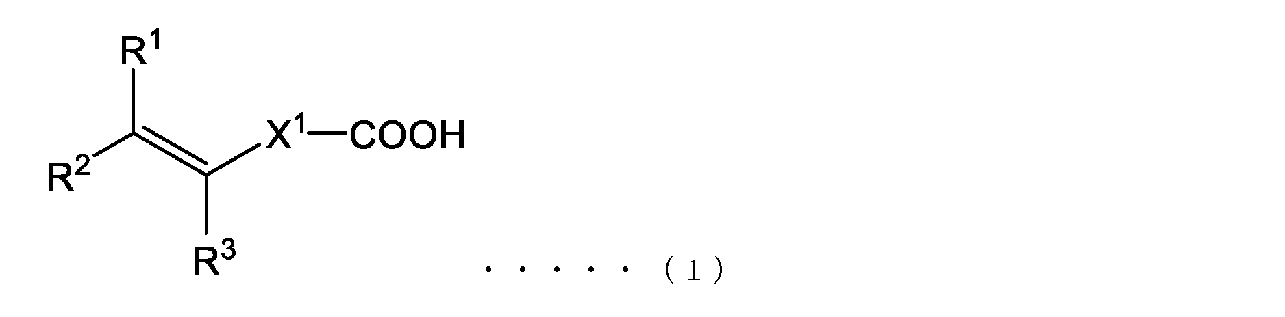
- the present invention provides the current collector according to [1], wherein the compound having a carboxy group is a compound represented by the following general formula (1):
- R 2 and R 3 each independently represent a hydrogen atom or an alkyl group having 1 to 5 carbon atoms
- X 1 represents a single bond or a divalent atomic group having 1 to 20 atoms in the main chain and a molecular weight of 500 or less.
- the present invention provides the current collector according to [1] or [2], wherein the vinylidene fluoride copolymer of the coating layer contains a constituent unit derived from vinylidene fluoride, and a constituent unit derived from acrylic acid and/or a constituent unit derived from monomethyl maleate.
- the present invention provides the current collector according to any one of [1] to [3], wherein the dispersant is at least one compound selected from the group consisting of polyvinylpyrrolidone, polyvinyl alcohol, methyl cellulose, hydroxypropyl methyl cellulose, and N-methylethanolamine.
- the present invention provides the current collector according to any one of [1] to [4], wherein an amount of the dispersant is 0.2 mass % or more with respect to a total mass of the coating layer.
- the present invention provides an electrode having a current collector according to any one of [1] to [5] and a composite layer disposed on a coating layer of the current collector, the composite layer including an active material and a binder.
- the present invention provides the electrode according to [6], wherein the binder contains a constituent unit derived from vinylidene fluoride.
- the present invention provides a battery comprising the electrode according to the above [6].
- the present invention also provides an electrode comprising the current collector described above and a mixture layer disposed on a coating layer of the current collector, the mixture layer containing an active material and a binder.
- the present invention provides a method for producing a current collector, comprising: applying a coating liquid containing a conductive assistant, a vinylidene fluoride copolymer, a dispersant, and a solvent to at least one surface of a substrate containing a metal, the vinylidene fluoride copolymer containing a constituent unit derived from vinylidene fluoride and a constituent unit derived from a compound having a carboxy group, and an amount of the conductive assistant is 45 mass % or more and 80 mass % or less with respect to a total amount of solids in the coating liquid.
- the present invention provides the method for producing a current collector according to [9], wherein the compound having a carboxy group is a compound represented by the following general formula (1):
- R2 and R3 each independently represent a hydrogen atom or an alkyl group having 1 to 5 carbon atoms;
- X1 represents a single bond or a divalent atomic group having a main chain with 1 to 20 atoms and a molecular weight of 500 or less.
- the current collector of the present invention is less likely to crack even when a composite layer is formed on it. Therefore, the current collector and electrodes using it are suitable as components for various lithium-ion secondary batteries.
- the current collector of the present invention is a current collector for use in lithium ion secondary batteries and the like, and has a base material containing a metal and a coating layer of a predetermined composition disposed on at least one surface of the base material.
- a composite layer is formed on the coating layer of the current collector before use.
- Patent Document 1 that is, a current collector having a substrate and a coating layer disposed on the substrate that contains acrylic acid-modified polyvinylidene fluoride (vinylidene fluoride copolymer obtained by copolymerizing acrylic acid and vinylidene fluoride) and a small amount of conductor, when a composite layer is formed on the coating layer, cracks tend to occur on the surface of the composite layer.
- acrylic acid-modified polyvinylidene fluoride vinylene fluoride copolymer obtained by copolymerizing acrylic acid and vinylidene fluoride
- the vinylidene fluoride copolymer used in the above coating layer which is a copolymer of acrylic acid and vinylidene fluoride, is very prone to agglomeration when mixed with a conductor, making it difficult to form a uniform coating layer.
- This agglomeration is thought to be due to the fact that the constituent units derived from vinylidene fluoride and the carboxyl groups derived from acrylic acid are located in close proximity to each other.
- the composite layer placed on the coating layer usually contains a vinylidene fluoride polymer. Therefore, the composite slurry for forming the composite layer often contains a good solvent that has a high affinity with the vinylidene fluoride copolymer in the coating layer.
- the vinylidene fluoride copolymer in the coating layer dissolves into the good solvent in the composite slurry. Then, when the dissolved vinylidene fluoride copolymer hardens again, the coating layer shrinks due to crystallization of the vinylidene fluoride copolymer. As a result, distortion is likely to occur within the composite layer placed on the coating layer, and it is thought that cracks will occur on the surface of the composite layer.
- the coating layer of the present invention contains a vinylidene fluoride copolymer containing a constituent unit derived from vinylidene fluoride and a constituent unit derived from a compound having a carboxyl group (for example, a compound represented by the general formula (1) described later), but the amount of the conductive assistant relative to the total mass of the coating layer is 45% by mass or more and 80% by mass or less. Therefore, even if the vinylidene fluoride copolymer is dissolved in a good solvent in the composite slurry when the composite slurry is applied onto the coating layer, the conductive assistant physically suppresses the movement of the vinylidene fluoride copolymer, and distortion is unlikely to occur in the composite layer.
- the addition of a dispersant can suppress the aggregation of the conductive assistant and the vinylidene fluoride copolymer. Therefore, it is considered that uneven parts are unlikely to occur in the coating layer formed on the substrate, and distortion of the coating layer itself is also suppressed. As a result, distortion and cracks are unlikely to occur in the composite layer formed on the coating layer of the current collector.
- the configuration of the current collector of the present invention will be described in detail below.
- the substrate is a base for the current collector, and the substrate may have sufficient conductivity and contain a metal.
- the substrate may contain only metal, or may contain a material other than metal (e.g., resin, ceramics, etc.). It is more preferable that the substrate is composed of only metal.
- the type of metal contained in the substrate is appropriately selected according to the type and shape of the current collector (and thus the battery).
- the substrate may contain only one type of metal, or may contain two or more types of metal. Examples of metals contained in the substrate include aluminum, copper, iron, stainless steel, steel, nickel, titanium, etc.
- the shape of the substrate is appropriately selected according to the type and size of the current collector (and thus the battery).
- the substrate may be, for example, a foil or metal mesh of the above-mentioned metals.
- the substrate may also be a material other than metal with the above-mentioned metal foil or metal mesh laminated on the surface.
- the coating layer needs to contain at least a predetermined amount of a conductive assistant, a vinylidene fluoride copolymer having a predetermined structure, and a dispersant, and may contain other components as necessary.
- the conductive assistant serves to electrically connect the substrate and the active material in the composite layer.
- Known conductive assistants can be used as the conductive assistant.
- Specific examples of the conductive assistant include acetylene black, ketjen black, carbon black, graphite powder, graphene, carbon nanofiber, carbon nanotube, carbon fiber, and metal powder.
- the coating layer may contain only one type of conductive assistant, or may contain two or more types.
- the amount of conductive additive in the coating layer may be 45.0% by mass or more and 80.0% by mass or less, preferably 47.0% by mass or more and 75.0% by mass or less, and more preferably 49.5% by mass or more and 65.0% by mass or less, relative to the total mass of the coating layer.
- the amount of conductive additive in the coating layer is 45% by mass or more, cracks and the like are less likely to occur in the composite layer formed on the current collector (coating layer).
- the amount of conductive additive in the coating layer is 80% by mass or less, the adhesive strength between the current collector and the composite layer is likely to be increased.
- Vinylidene fluoride copolymer contains a constituent unit derived from vinylidene fluoride and a constituent unit derived from a compound having a carboxy group.
- the coating layer may contain only one type of vinylidene fluoride copolymer, or may contain two or more types.
- the amount of the constituent units derived from vinylidene fluoride in the vinylidene fluoride copolymer is preferably 90.0 mol% or more and 99.99 mol% or less, more preferably 93.0 mol% or more and 99.98 mol% or less, and particularly preferably 96.0 mol% or more and 99.97 mol% or less, based on the amount (mol) of all the constituent units constituting the vinylidene fluoride copolymer.
- the amount of the constituent units derived from vinylidene fluoride is 90.0 mol% or more, the properties derived from vinylidene fluoride, such as electrochemical stability, are easily obtained in the coating layer.
- the amount of the constituent units derived from vinylidene fluoride in the vinylidene fluoride copolymer can be specified by 19 F-NMR.
- the compound having a carboxy group is not particularly limited, and examples thereof include a compound represented by the following general formula (1).
- the compound represented by the general formula (1) will be described as an example, but the structure of the compound having a carboxy group is not limited thereto.
- the vinylidene fluoride polymer may contain only one type of structural unit derived from the compound represented by the following general formula (1), or may contain two or more types.
- R2 and R3 each independently represent a hydrogen atom or an alkyl group having 1 to 5 carbon atoms. From the viewpoint of polymerization reactivity, a substituent with little steric hindrance is preferable, hydrogen or an alkyl group having 1 to 3 carbon atoms is preferable, and hydrogen or a methyl group is preferable.
- X1 represents a single bond or a divalent atomic group having 1 to 20 atoms in the main chain and a molecular weight of 500 or less.
- the number of atoms in the main chain of X1 is the number of atoms constituting the shortest chain connecting the terminal carboxy group and the carbon-carbon double bond in the above general formula (1).
- the number of atoms in the main chain is more preferably 15 or less.
- the atomic group represented by X1 is not particularly limited in structure as long as it has a molecular weight of 500 or less and satisfies the above-mentioned number of atoms in the main chain, and may be linear, branched, or contain a ring structure.
- compounds represented by the above general formula (1) include monomethyl maleate (MMM), acrylic acid (AA), methacrylic acid, carboxymethyl acrylate, carboxymethyl methacrylate, 2-carboxyethyl acrylate, 2-carboxyethyl methacrylate, acryloyloxyethyl succinic acid, methacryloyloxyethyl succinic acid, acryloyloxyethyl phthalic acid, methacryloyloxyethyl phthalic acid, acryloyloxypropyl succinic acid, methacryloyloxypropyl succinic acid, etc.
- acrylic acid or monomethyl maleate is preferred.
- the amount of the constituent units derived from the compound having a carboxy group (e.g., the compound represented by the general formula (1)) in the vinylidene fluoride copolymer is preferably 0.01 mol% or more and 10.0 mol% or less, more preferably 0.02 mol% or more and 7.0 mol% or less, and particularly preferably 0.03 mol% or more and 4.0 mol% or less, relative to the amount (mol) of all the constituent units constituting the vinylidene fluoride copolymer.
- the amount of the constituent units derived from the compound having a carboxy group e.g., the compound represented by the general formula (1)
- the adhesion between the coating layer and the composite layer or the substrate is likely to be further improved.
- these amounts are 10.0 mol% or less, the amount of the constituent units derived from vinylidene fluoride becomes relatively large, and the electrochemical stability of the vinylidene fluoride copolymer and therefore the electrochemical stability of the coating layer are likely to be good.
- the amount of constitutional units derived from a compound having a carboxy group can be analyzed by 19 F-NMR, 1 H-NMR or the like.
- the vinylidene fluoride copolymer may contain structural units derived from compounds other than vinylidene fluoride and compounds having a carboxyl group (for example, compounds represented by general formula (1)) (hereinafter also referred to as "other compounds"), within a range that does not impair the object and effect of the present invention.
- the amount (total amount) of structural units derived from other compounds relative to the total structural units (number of moles) of the vinylidene fluoride copolymer is preferably 10.0 mol% or less, more preferably 4.0 mol% or less.
- the amount of structural units derived from other compounds in the vinylidene fluoride copolymer is 10.0 mol% or less, the electrochemical stability of the coating layer is improved, and the adhesive strength between the coating layer and the substrate is likely to be increased.
- the amount of structural units derived from other compounds can be analyzed by 19 F-NMR, 1 H-NMR, or the like.
- Examples of other compounds include fluorine-based compounds other than vinylidene fluoride, such as vinyl fluoride, trifluoroethylene, tetrafluoroethylene, chlorotrifluoroethylene, hexafluoropropylene, hexafluoroethylene, fluoroalkyl vinyl ethers, and perfluoromethyl vinyl ether.
- fluorine-based compounds other than vinylidene fluoride such as vinyl fluoride, trifluoroethylene, tetrafluoroethylene, chlorotrifluoroethylene, hexafluoropropylene, hexafluoroethylene, fluoroalkyl vinyl ethers, and perfluoromethyl vinyl ether.
- the inherent viscosity of the vinylidene fluoride copolymer is preferably 1.0 or more, more preferably 1.3 dL/g or more, and more preferably 2.0 dL/g or more.
- the inherent viscosity can be measured by the following method. First, 80 mg of the vinylidene fluoride copolymer is dissolved in 20 mL of N,N-dimethylformamide, and the viscosity is measured using an Ubbelohde viscometer in a thermostatic bath at 30°C.
- the inherent viscosity ( ⁇ i ) of the vinylidene fluoride copolymer is calculated from the obtained value based on the following formula.
- ⁇ i (1/C) ⁇ ln( ⁇ / ⁇ 0 )
- ⁇ is the viscosity of the solution
- ⁇ 0 is the viscosity of the solvent
- N,N-dimethylformamide alone is the concentration of the vinylidene fluoride copolymer, that is, 0.4 g/dL.
- the method for preparing the vinylidene fluoride copolymer is not particularly limited, and vinylidene fluoride and a structural unit derived from a compound having a carboxy group (e.g., a compound represented by general formula (1)), and other compounds as necessary, may be polymerized by a known method.
- Examples of polymerization methods include suspension polymerization, emulsion polymerization, solution polymerization, etc.
- the amount of vinylidene fluoride copolymer in the coating layer is preferably 10.0% by mass or more and 54.8% by mass or less, more preferably 15.0% by mass or more and 52.8% by mass or less, and even more preferably 25.0% by mass or more and 50.3% by mass or less, based on the total mass of the coating layer.
- the amount of vinylidene fluoride copolymer is within this range, the electrochemical stability of the coating layer is likely to be improved, and further, the adhesion between the coating layer and the substrate and the adhesion between the current collector and the composite layer are likely to be improved.
- the amount of vinylidene fluoride copolymer is preferably 25 parts by mass or more and 122 parts by mass or less, more preferably 53.8 parts by mass or more and 102 parts by mass or less, based on 100 parts by mass of the conductive assistant described above.
- the ratio of the amount of the conductive assistant to the amount of the vinylidene fluoride copolymer is within this range, the composite layer formed on the current collector layer is less likely to crack.
- the ratio of the amount of conductive assistant to the amount of vinylidene fluoride copolymer is within the above range, the adhesion between the current collector and the composite layer tends to be even better.
- the dispersant in this specification may be any compound capable of suppressing the aggregation of the vinylidene fluoride copolymer and the conductive assistant, and examples thereof include vinyl copolymers, cellulose compounds, and alcohol amines.
- the coating layer contains a dispersant, so that the composite layer formed on the current collector (coating layer) is less likely to crack, and the adhesion between the coating layer and the composite layer is also improved.
- the coating layer may contain only one type of dispersant, or may contain two or more types of dispersants.
- the vinyl copolymer examples include polyvinylpyrrolidone, polyvinyl alcohol, etc.
- examples of the cellulose compound include methyl cellulose, hydroxypropyl methyl cellulose, etc.
- the alcohol amine may be any compound in which one or more alkyl alcohols are bonded to the nitrogen atom of an amine, and examples thereof include N-methylethanolamine.
- preferred examples of the dispersant include polyvinylpyrrolidone, polyvinyl alcohol, methyl cellulose, hydroxypropyl methyl cellulose, and N-methylethanolamine.
- the dispersant may be liquid or solid at room temperature, but it is preferable that it has good compatibility with N-methyl-2-pyrrolidone.
- the amount of dispersant is preferably 0.2% by mass or more and 10.0% by mass or less, and more preferably 0.4% by mass or more and 10.0% by mass or less, relative to the total mass of the coating layer. When the amount of dispersant is within this range, cracks are even less likely to occur in the composite layer formed on the current collector layer (coating layer).
- the coating layer may contain other components within the scope of the present invention, examples of which include nitrogen compounds such as phosphorus compounds, sulfur compounds, organic acids, amine compounds, and ammonium compounds; organic esters, silane-based, titanium-based, and aluminum-based coupling agents; resins such as polytetrafluoroethylene (PTFE), styrene-butadiene rubber (SBR), and polyacrylonitrile (PAN).
- nitrogen compounds such as phosphorus compounds, sulfur compounds, organic acids, amine compounds, and ammonium compounds
- organic esters silane-based, titanium-based, and aluminum-based coupling agents
- resins such as polytetrafluoroethylene (PTFE), styrene-butadiene rubber (SBR), and polyacrylonitrile (PAN).
- PTFE polytetrafluoroethylene
- SBR styrene-butadiene rubber
- PAN polyacrylonitrile
- the amount of the other components is preferably 10% by mass or less, and
- the coating layer may be disposed on one side of the above-mentioned substrate, or may be formed on both sides.
- the coating layer may be disposed in a pattern on one side of the substrate, but is preferably disposed so as to entirely cover one side or both sides of the substrate, from the viewpoint of easily suppressing cracks in the composite layer and reducing electrical resistance between the composite layer and the substrate.
- the thickness of the coating layer on at least one surface of the substrate is preferably 0.5 ⁇ m to 10 ⁇ m, and more preferably 0.8 ⁇ m to 5 ⁇ m. If the coating layer is 0.5 ⁇ m or more thick, the adhesive strength between the coating layer and the composite layer tends to be good. On the other hand, if the coating layer is 10 ⁇ m or less thick, the energy density of the battery using the current collector can be increased.
- the manufacturing method of the current collector of the present invention is not particularly limited as long as it is a method capable of forming a coating layer on the above-mentioned base material, but a method including a step of applying a coating liquid to at least one surface of the above-mentioned base material (hereinafter also referred to as a "coating step") and a step of drying the coating liquid (hereinafter also referred to as a “drying step”).
- a coating step a coating liquid to at least one surface of the above-mentioned base material
- drying step a step of drying the coating liquid
- the coating liquid applied in the coating step needs to contain at least the conductive assistant, the vinylidene fluoride copolymer, the dispersant, and the organic solvent, and may contain other components as necessary.
- the conductive assistant, the vinylidene fluoride copolymer, the dispersant, and the other components are as described above.
- the organic solvent contained in the coating liquid may be any organic solvent capable of uniformly dispersing or dissolving the conductive assistant, the vinylidene fluoride copolymer, and the dispersant.
- the organic solvent include amide compounds such as dimethylformamide, N,N-dimethylacetamide, and N-methylpyrrolidone; alcohols such as methanol, ethanol, isopropyl alcohol, 2-ethyl-1-hexanol, 1-nonanol, lauryl alcohol, and tripropylene glycol; amine compounds such as o-toluidine, m-toluidine, and p-toluidine; 1-ethyl-3-methylimidazolium bis(trifluoromethylsulfonyl)imide; lactones such as ⁇ -butyrolactone and ⁇ -butyrolactone; sulfoxide and sulfone compounds such as dimethyl sulfoxide and sulfolane.
- the amount of the organic solvent is appropriately selected depending on the type of organic solvent, the desired viscosity of the coating liquid, etc., but is usually preferably 1,000 parts by mass or more and 10,000 parts by mass or less, and more preferably 3,000 parts by mass or more and 7,000 parts by mass or less, per 100 parts by mass of the total amount of the conductive assistant and the vinylidene fluoride copolymer.
- the method for applying the coating liquid to the substrate there are no particular limitations on the method for applying the coating liquid to the substrate, and methods that can be used include the doctor blade method, reverse roll method, comma bar method, gravure method, air knife method, die coating method, and dip coating method.
- Drying process After the coating liquid is applied, the coating liquid is heated at an arbitrary temperature to volatilize the organic solvent to obtain a coating layer.
- the heating temperature is not particularly limited, and in one example, it is preferably 60°C or higher, and more preferably 80°C or higher. The upper limit is appropriately selected depending on the type of coating liquid. Heating may be performed multiple times at different temperatures.
- the drying process may be performed under any environment, such as atmospheric pressure, pressurized pressure, or reduced pressure.
- Electrode The electrode of the present invention has the above-mentioned current collector and a composite layer containing an active material and a binder disposed on the current collector.
- the composite layer may contain an active material and a binder, and the type of the binder is not particularly limited, but it is preferable that the binder contains a vinylidene fluoride homopolymer or a vinylidene fluoride-based polymer containing a constituent unit derived from vinylidene fluoride and a constituent unit derived from hexafluoropropylene and/or a constituent unit derived from a compound represented by the general formula (2) described below.
- Each component of the electrode will be described below.
- the active material contained in the mixture layer may be a positive electrode active material or a negative electrode active material, and is appropriately selected depending on the application.
- the negative electrode active material examples include carbon materials such as artificial graphite, natural graphite, non-graphitizable carbon, graphitizable carbon, activated carbon, or phenolic resin and pitch, etc., which are fired and carbonized; metal and alloy materials such as Cu, Li, Mg, B, Al, Ga, In, Si, Ge, Sn, Pb, Sb, Bi, Cd, Ag, Zn, Hf, Zr, and Y; and metal oxides such as SiO, SiO 2 , GeO, GeO 2 , SnO, SnO 2 , PbO, PbO 2 , and Li 4 Ti 5 O 12 (LTO).
- the negative electrode active material may be one whose surface is coated, and may contain one type alone or two or more types.
- the negative electrode active material may be a commercially available product.
- examples of the positive electrode active material include lithium-based positive electrode active materials, such as lithium metal oxides represented by the following general formula (a) and those having a coating applied to the surface thereof.
- M represents at least one metal element including Ni, and the metal element other than Ni is preferably selected from the group consisting of Co, Al, Fe, Mn, Cr and V. In addition to Ni, it is more preferable to further contain one or more metals selected from the group consisting of Co, Mn and Al.
- the lithium metal oxide represented by the above formula (a) when the total of the metal elements constituting M is 100 mol%, it is preferable to contain 55 mol% or more of Ni, and more preferably to contain 70 mol% or more of Ni. In the above general formula (a), 0.5 ⁇ x ⁇ 1.5, and more preferably 0.7 ⁇ x ⁇ 1.3.
- Examples of the composition of the lithium -based positive electrode active material represented by the above general formula ( a ) and other lithium - based positive electrode active materials include Li1.0Ni0.8Co0.2O2 , Li1.0Ni0.5Mn0.5O2 , Li1.00Ni0.35Co0.34Mn0.34O2 ( NCM111 ) , Li1.00Ni0.52Co0.20Mn0.30O2 ( NCM523 ) , Li1.00Ni0.50Co0.30Mn0.20O2 ( NCM532 ) , Li1.00Ni0.6Co0.2Mn0.2O2 (NCM622), Li 1.00 Ni 0.83 Co 0.12 Mn 0.05 O 2 (NCM811), Li 1.00 Ni 0.85 Co 0.15 Al 0.05 O 2 (NCA811), LiCoO 2 (LCO), LiMn 2 O 4 (LMO), LiFePO 4 (LFP), and LiMnPO 4 (LMP), LiMn 1-x Fe x PO 4 (LFMP).
- the positive electrode active material may be
- the amount of active material contained in the composite layer is appropriately selected depending on the type, the function of the electrode, the type of battery, etc., and is not particularly limited, but in one example, it is preferably 50.0 mass% or more and 99.9 mass% or less with respect to the total amount of the composite layer. If the amount of active material is within this range, for example, sufficient charge/discharge capacity is obtained, and the battery performance is likely to be good.
- Binder The binder contained in the composite layer is not particularly limited as long as it can bind the active material, but as described above, it is preferable to contain a vinylidene fluoride homopolymer or a vinylidene fluoride copolymer containing a constituent unit derived from vinylidene fluoride and a constituent unit derived from hexafluoropropylene and/or a constituent unit derived from a compound represented by the general formula (2) described below (hereinafter also referred to as "vinylidene fluoride polymer A").
- the binder may contain only vinylidene fluoride homopolymer, may contain only vinylidene fluoride polymer A, or may contain both. When the binder contains vinylidene fluoride polymer A, the binder may contain only one type of vinylidene fluoride polymer A, or may contain two or more types.
- the vinylidene fluoride homopolymer that can be used as a binder is similar to known vinylidene fluoride homopolymers. There are no particular limitations on the method for preparing the vinylidene fluoride homopolymer, and vinylidene fluoride may be polymerized by a known method. Examples of polymerization methods include suspension polymerization, emulsion polymerization, solution polymerization, etc.
- the vinylidene fluoride polymer A may be a polymer containing a constituent unit derived from vinylidene fluoride, a constituent unit derived from hexafluoropropylene, and/or a constituent unit derived from a compound represented by general formula (2).
- the vinylidene fluoride polymer A may be, for example, a copolymer of vinylidene fluoride and hexafluoropropylene, a copolymer of vinylidene fluoride and a compound represented by general formula (2), or a copolymer of vinylidene fluoride, hexafluoropropylene, and a compound represented by general formula (2).
- the vinylidene fluoride polymer A may also contain other copolymerization components within a range that does not impair the object and effect of the present invention.
- the amount of the constituent units derived from vinylidene fluoride in the vinylidene fluoride polymer A is preferably 50 mol% or more, more preferably 60 mol% or more, and particularly preferably 80 mol% or more, based on the amount (mol) of all constituent units constituting the vinylidene fluoride polymer A.
- the amount of the constituent units derived from vinylidene fluoride in the vinylidene fluoride polymer A can be determined by 19F -NMR.
- the amount of the hexafluoropropylene-derived structural units in the vinylidene fluoride polymer A is more preferably 10 mol % or less relative to the amount (mol) of all structural units constituting the vinylidene fluoride polymer A.
- the amount of the hexafluoropropylene-derived structural units is within the above range, the melting point of the vinylidene fluoride polymer A tends to fall within a desired range, and the adhesive strength between the vinylidene fluoride polymer A and the above-mentioned active material and the like is increased.
- the amount of the hexafluoropropylene-derived structural units in the vinylidene fluoride polymer A can be determined by 19 F-NMR.
- the vinylidene fluoride polymer A may contain only one type of structural unit derived from the compound represented by the following general formula (2), or may contain two or more types.
- R5 and R6 each independently represent a hydrogen atom or an alkyl group having 1 to 5 carbon atoms. From the viewpoint of polymerization reactivity, a substituent with little steric hindrance is preferable, hydrogen or an alkyl group having 1 to 3 carbon atoms is preferable, and hydrogen or a methyl group is preferable.
- X2 in the above general formula (2) represents a single bond or a divalent atomic group having 1 to 20 atoms in the main chain and a molecular weight of 500 or less.
- the number of atoms in the main chain of X2 is the number of atoms constituting the shortest chain connecting the terminal carboxy group and the carbon-carbon double bond in the above general formula (2).
- the number of atoms in the main chain is more preferably 15 or less.
- the atomic group represented by X2 is not particularly limited in structure as long as it has a molecular weight of 500 or less and satisfies the above-mentioned number of atoms in the main chain, and may be linear, branched, or contain a ring structure.
- compounds represented by the above general formula (2) include monomethyl maleate (MMM), acrylic acid (AA), methacrylic acid, carboxymethyl acrylate, carboxymethyl methacrylate, 2-carboxyethyl acrylate, 2-carboxyethyl methacrylate, acryloyloxyethyl succinic acid, methacryloyloxyethyl succinic acid, acryloyloxyethyl phthalic acid, methacryloyloxyethyl phthalic acid, acryloyloxypropyl succinic acid, methacryloyloxypropyl succinic acid, etc.
- the amount of the structural unit derived from the compound represented by the general formula (2) is preferably 0.01 mol% or more and 10 mol% or less, more preferably 0.02 mol% or more and 7 mol% or less, and particularly preferably 0.03 mol% or more and 4 mol% or less, based on the amount (mol) of all structural units constituting the vinylidene fluoride polymer A.
- the amount of the structural unit derived from the compound represented by the general formula (2) is 0.01 mol% or more, the adhesive strength between the binder and the active material and the adhesive strength between the composite layer and the coat layer are increased.
- the amount of the structural unit derived from the compound represented by the general formula (2) is 10 mol% or less, the amount of the structural unit derived from vinylidene fluoride is relatively large, and the electrochemical stability of the composite layer is likely to be good.
- the amount of the structural unit derived from the compound represented by the general formula (2) in the vinylidene fluoride polymer A can be analyzed by 19 F-NMR, 1 H-NMR, or the like.
- the vinylidene fluoride polymer A may partially contain structural units derived from compounds other than vinylidene fluoride, hexafluoropropylene, and the compound represented by the general formula (2) (hereinafter also referred to as "other compounds") within a range that does not impair the purpose and effects of the present invention.
- other compounds include the other compounds listed in the description of the vinylidene fluoride copolymer of the coating layer above.
- the amount of structural units derived from other compounds is preferably 10 mol% or less with respect to the amount (mol) of all structural units constituting the vinylidene fluoride polymer A.
- the amount of structural units derived from other compounds in the vinylidene fluoride polymer A is 10 mol% or less, the electrochemical stability of the composite layer is likely to be increased, and the adhesive strength between the composite layer and the coating layer is likely to be increased.
- the amount of structural units derived from other compounds can be analyzed by 19 F-NMR, 1 H-NMR, or the like.
- the method for preparing the vinylidene fluoride polymer A is not particularly limited, and vinylidene fluoride, hexafluoropropylene and/or the compound represented by the general formula (2) above, and other compounds as necessary may be polymerized by a known method.
- Examples of the polymerization method include suspension polymerization, emulsion polymerization, solution polymerization, etc.
- the amount of binder in the composite layer is appropriately selected depending on the binder composition, the function of the electrode, the type of battery, etc., and is not particularly limited, but in one example, it is preferably 0.1 mass % or more and 50 mass % or less with respect to the total amount of the composite layer. When the amount of binder is within this range, the adhesive strength between the composite layer and the coating layer is good. In addition, since the amount of active material is relatively sufficient, sufficient charge/discharge capacity is obtained, and the battery performance is likely to be good.
- the composite layer may contain known dispersants, adhesive assistants, thickeners, etc., within the scope that does not impair the purpose and effect of the present invention.
- it may further contain nitrogen compounds such as phosphorus compounds, sulfur compounds, organic acids, amine compounds, and ammonium compounds; organic esters, various silane-based, titanium-based, and aluminum-based coupling agents; resins such as polytetrafluoroethylene (PTFE), styrene-butadiene rubber (SBR), and polyacrylonitrile (PAN).
- PTFE polytetrafluoroethylene
- SBR styrene-butadiene rubber
- PAN polyacrylonitrile
- the composite layer can be formed by applying a composite slurry containing the above-mentioned active material, binder, and optionally other components and an organic solvent onto the coating layer of the current collector by a known method, and drying the mixture slurry by a known method.
- the organic solvent contained in the composite slurry is the same as that used in the coating liquid.
- Batteries The current collectors and electrodes described above can be used in various lithium ion secondary batteries and the like, but may also be used for other purposes.
- VDF/AA1 Vinylidene fluoride/acrylic acid copolymer (prepared in Preparation Example 1 below)
- VDF/AA2 Vinylidene fluoride/acrylic acid copolymer (prepared in Preparation Example 2 below)
- VDF/MMM vinylidene fluoride/monomethyl maleate copolymer (prepared in Preparation Example 3 below)
- VDF/AES vinylidene fluoride/acryloyloxyethyl succinate (prepared in Preparation Example 4 below)
- PVDF Vinylidene fluoride homopolymer (prepared in Preparation Example 5 below)
- the mass ratio of the conductive assistant (Super-P) and the vinylidene fluoride copolymer (VDF/AA1) in the coating solution was 50:50.
- the amount of the dispersant (PVP) was 1% by mass with respect to the total amount of the vinylidene fluoride copolymer and the conductive assistant.
- the obtained coating solution was applied onto a 15 ⁇ m-thick aluminum foil (substrate) serving as a current collector using a TH-C type coater manufactured by Thank Metal Co., Ltd., and dried to form a coating layer with a basis weight of approximately 0.7 g/ m2 .
- PVDF vinylidene fluoride homopolymer
- NMP conductive additive CNT
- MWCNT Multi-Walled CNT
- the positive electrode active material LFP lithium iron phosphate: primary particle diameter: D50: 2 ⁇ m, specific surface area: 19.9 m 2 /g
- LFP positive electrode active material
- CNT conductive assistant
- vinylidene fluoride homopolymer in the composite slurry was 100:2:2, in this order.
- the obtained composite slurry was applied onto the coating layer using a TH-C type coater manufactured by Sank Metals, and dried to form a composite layer with a basis weight of approximately 150 g/m 2.
- the basis weight of the composite layer was approximately 150 g/m 2 .
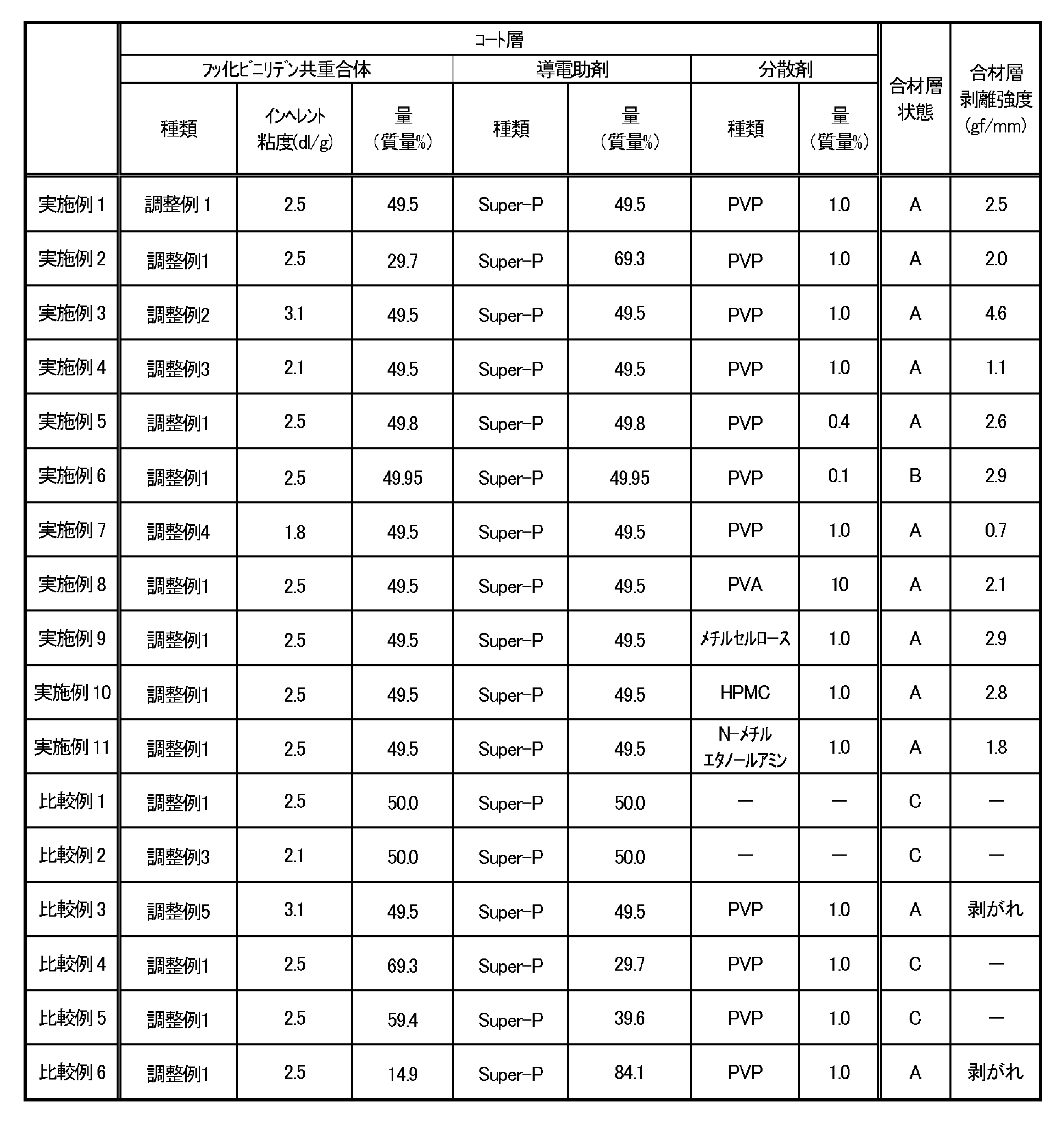
- Example 2 to 11 and Comparative Examples 1 to 6 An electrode was prepared in the same manner as in Example 1, except that the type and amount of vinylidene fluoride (co)polymer and the type and amount of dispersant in the coating solution used to form the coating layer were changed as shown in Table 1.
- the inherent viscosity of the above-mentioned vinylidene fluoride (co)polymer was measured as follows. First, 80 mg of vinylidene fluoride (co)polymer was dissolved in 20 mL of N,N-dimethylformamide, and the viscosity was measured using an Ubbelohde viscometer in a thermostatic bath at 30°C. Then, the inherent viscosity ( ⁇ i ) of the vinylidene fluoride (co)polymer was calculated from the obtained value based on the following formula.
- ⁇ i (1/C) ⁇ ln( ⁇ / ⁇ 0 )
- ⁇ is the viscosity of the solution
- ⁇ 0 is the viscosity of the solvent
- N,N-dimethylformamide alone is the concentration of the vinylidene fluoride polymer, that is, 0.4 g/dL.
- Electrode condition After the formation of the composite layer, the composite layer was visually observed, and those with cracks were rated C, those with minor cracks were rated B, and those without cracks were rated A.
- the electrode was pressed with a roll press and the electrode density was adjusted to 2.3 g/ cm3 , the cracks in the composite layer rated B were repaired and no longer observed.
- the cracks in the composite layer rated C were not repaired even when the electrode was similarly roll pressed.
- Peel strength measurement After roll pressing, electrodes in which no cracks were observed (those rated A and B) were subjected to a peel strength measurement between the composite layer and the coating layer. A sample was cut to a length of 50 mm and a width of 20 mm, and a 90-degree peel test was performed at a head speed of 10 mm/min using a tensile tester ("STB-1225S" manufactured by A&D Co., Ltd.) in accordance with JIS K6854-1 to measure the peel strength (gf/mm). The current collector peeled off from the composite layer before the measurement was expressed as "peeling".
- the coating layer contained a conductive assistant, a vinylidene fluoride copolymer having a structural unit derived from the above-mentioned compound having a carboxy group (compound represented by general formula (1)), and a dispersant
- the amount of the conductive assistant was 45 mass% or more and 80 mass% or less relative to the total mass of the coating layer (Examples 1 to 11)
- the composite layer was less likely to crack, and the adhesion between the composite layer and the coating layer (current collector) was good.
- a conductive assistant in a specified range and further containing a dispersant, it was possible to suppress the aggregation of the above-mentioned vinylidene fluoride copolymer.
- the current collector of the present invention is less likely to cause cracks on the surface of the electrode, and high-quality electrodes and batteries can be produced. Therefore, the current collector is very useful for producing lithium-ion secondary batteries and the like.
Landscapes
- Chemical & Material Sciences (AREA)
- Chemical Kinetics & Catalysis (AREA)
- Electrochemistry (AREA)
- General Chemical & Material Sciences (AREA)
- Engineering & Computer Science (AREA)
- Materials Engineering (AREA)
- Manufacturing & Machinery (AREA)
- Composite Materials (AREA)
- Battery Electrode And Active Subsutance (AREA)
- Addition Polymer Or Copolymer, Post-Treatments, Or Chemical Modifications (AREA)
Abstract
Description
[2]本発明は、前記カルボキシ基を有する化合物が、下記一般式(1)で表される化合物である、[1]に記載の集電体を提供する。
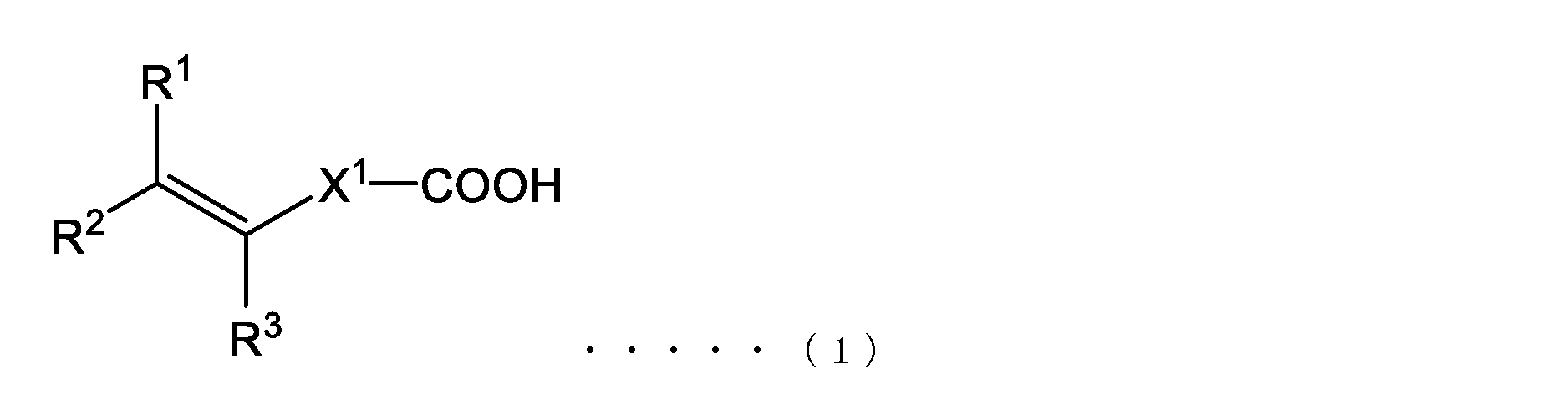
[3]本発明は、前記コート層のフッ化ビニリデン共重合体が、フッ化ビニリデン由来の構成単位と、アクリル酸由来の構成単位および/またはマレイン酸モノメチル由来の構成単位と、を含む、[1]または[2]に記載の集電体を提供する。
[4]本発明は、前記分散剤が、ポリビニルピロリドン、ポリビニルアルコール、メチルセルロース、ヒドロキシプロピルメチルセルロース、およびN-メチルエタノールアミンからなる群から選ばれる少なくとも一種の化合物である、[1]~[3]のいずれかに記載の集電体を提供する。
[5]本発明は、前記分散剤の量が、前記コート層の全質量に対して、0.2質量%以上である、[1]~[4]のいずれかに記載の集電体を提供する。
[8]本発明は、上記[6]に記載の電極を備える、電池を提供する。
また、本発明は、前述の集電体と、前記集電体のコート層上に配置された合材層と、を有し、前記合材層は、活物質およびバインダーを含む、電極を提供する。
[10]本発明は、前記カルボキシ基を有する化合物が、下記一般式(1)で表される化合物である、[9]に記載の集電体の製造方法を提供する。

R1は、水素原子、炭素数1以上5以下のアルキル基、または-C(=O)-OCnH2n+1(nは1以上5以下)を表し、
R2およびR3は、それぞれ独立に、水素原子、または炭素数1以上5以下のアルキル基を表し、
X1は、単結合、または主鎖の原子数が1以上20以下であり、かつ分子量500以下の二価の原子団を表す)
本発明の集電体は、リチウムイオン二次電池等に使用するための集電体であり、金属を含む基材と、当該基材の少なくとも一方の面に配置された、所定の組成のコート層と、を有する。通常、当該集電体のコート層上に合材層を形成して使用される。
以下、本発明の集電体の構成について、詳しく説明する。
基材は、集電体のベースとなる構成であり、当該基材は、十分な導電性を有し、かつ金属を含んでいればよい。基材は、金属のみを含んでいてもよく、金属以外の材料(例えば樹脂やセラミックス等)を含んでいてもよい。基材は、金属のみで構成されることがより好ましい。ここで、基材が含む金属の種類は、集電体(ひいては電池)の種類や形状等に合わせて適宜選択される。基材は、金属を1種のみ含んでいてもよく、2種以上含んでいてもよい。基材が含む金属の例には、アルミニウム、銅、鉄、ステンレス鋼、鋼、ニッケル、チタン等が含まれる。
コート層は、所定の量の導電助剤、所定の構造のフッ化ビニリデン共重合体、および分散剤を少なくとも含んでいればよく、必要に応じて他の成分を含んでいてもよい。
当該導電助剤は、上記基材と合材層中の活物質とを電気的に導通させる役割を果たす。当該導電助剤としては、公知の導電助剤を使用可能である。導電助剤の具体例には、アセチレンブラック、ケッチェンブラック、カーボンブラック、黒鉛粉末、グラフェン、カーボンナノファイバー、カーボンナノチューブ、カーボンファイバー、および金属粉末等が含まれる。コート層は、当該導電助剤を1種のみ含んでいてもよく、2種以上含んでいてもよい。
フッ化ビニリデン共重合体は、フッ化ビニリデン由来の構成単位と、カルボキシ基を有する化合物由来の構成単位と、を含む。コート層は、フッ化ビニリデン共重合体を一種のみ含んでいてもよく、二種以上含んでいてもよい。
ηi=(1/C)・ln(η/η0)
なお、上記式におけるηは溶液の粘度、η0は溶媒であるN,N-ジメチルホルムアミド単独の粘度、Cはフッ化ビニリデン共重合体の濃度、すなわち0.4g/dLである。
本明細書における分散剤は、上記フッ化ビニリデン共重合体および導電助剤の凝集を抑制可能な化合物であればよく、その例には、ビニル系共重合体、セルロース系化合物、およびアルコールアミンが含まれる。上述のように、コート層が分散剤を含むことで、集電体(コート層)上に形成する合材層にひび割れが生じ難くなり、かつコート層と合材層との密着性も良好になる。コート層は、分散剤を一種のみ含んでいてもよく、二種以上含んでいてもよい。
コート層は、上述の導電助剤、フッ化ビニリデン共重合体、および分散剤の他に、本発明の目的および効果を損なわない範囲で、他の成分を含んでいてもよく、その例には、リン化合物、硫黄化合物、有機酸、アミン化合物、およびアンモニウム化合物等の窒素化合物;有機エステル、シラン系、チタン系およびアルミニウム系のカップリング剤;ポリテトラフルオロエチレン(PTFE)、スチレン・ブタジエンゴム(SBR)、およびポリアクリロニトリル(PAN)等の樹脂;が含まれる。ただし、当該他の成分の量は、コート層の総質量に対して、10質量%以下が好ましく、5質量%以下がさらに好ましい。
また、上記コート層は、上述の基材の一方の面に配置されていればよく、両面に形成されていてもよい。また、コート層は、基材の一方の面にパターン状に配置されていてもよいが、基材の一方の面、もしくは両方の面を全て覆うように配置されていることが、合材層のひび割れを抑制したり、合材層と基材との間の電気的抵抗を低減したりしやすいとの観点で好ましい。
本発明の集電体の製造方法は、上述の基材上にコート層を形成可能な方法であれば特に制限されないが、上述の基材の少なくとも一方の面に、コート液を塗布する工程(以下、「塗布工程」とも称する)と、当該コート液を乾燥させる工程(以下、「乾燥工程」とも称する)と、を含む方法が好ましい。以下、各工程について説明する。
塗布工程で塗布するコート液は、上述の導電助剤と、フッ化ビニリデン共重合体と、分散剤と、有機溶媒と、を少なくとも含んでいればよく、必要に応じて他の成分を含んでいてもよい。導電助剤や、フッ化ビニリデン共重合体、分散剤、および他の成分については、上述の通りである。
上記コート液の塗布後、任意の温度で加熱し、有機溶媒を揮発させてコート層を得る。加熱温度は特に制限されず、一例において、60℃以上が好ましく、80℃以上がより好ましい。上限値は、コート液の種類に応じて適宜選択される。加熱は、異なる温度で複数回行ってもよい。また、乾燥工程は、大気圧下、加圧下、減圧下のいずれの環境で行ってもよい。
本発明の電極は、上述の集電体と、当該集電体上に配置された、活物質およびバインダーを含む合材層と、を有する。合材層は、活物質およびバインダーを含んでいればよく、その種類は特に制限されないが、バインダーが、フッ化ビニリデン単独重合体、もしくはフッ化ビニリデン由来の構成単位と、ヘキサフルオロプロピレン由来の構成単位および/または後述の一般式(2)で表される化合物由来の構成単位とを含むフッ化ビニリデン系重合体を含むことが好ましい。以下、当該電極の各構成について説明する。
合材層が含む活物質は、正極活物質であってもよく、負極活物質であってもよく、その用途に応じて適宜選択される。
LiMxO2・・・(a)
一般式(a)において、MはNiを含む少なくとも一種の金属元素を表し、Ni以外の金属元素としては、Co、Al、Fe、Mn、CrおよびVからなる群から選択されることが好ましい。Niに加えて、さらにCo、MnおよびAlからなる群から選択される1種または2種以上の金属を含有することがより好ましい。また、上記式(a)で表されるリチウム金属酸化物において、Mを構成する金属元素の合計を100モル%としたとき、55モル%以上のNiを含むことが好ましく、70%以上のNiを含むことがより好ましい。
上記一般式(a)において、0.5≦x≦1.5であり、さらに好ましくは0.7≦x≦1.3である。
合材層が含むバインダーは、上記活物質を結着可能であれば特に制限されないが、上述のように、フッ化ビニリデン単独重合体、もしくはフッ化ビニリデン由来の構成単位と、ヘキサフルオロプロピレン由来の構成単位および/または後述の一般式(2)で表される化合物由来の構成単位とを含むフッ化ビニリデン共重合体(以下、「フッ化ビニリデン系重合体A」とも称する)を含むことが好ましい。バインダーは、フッ化ビニリデン単独重合体のみを含んでいてもよく、フッ化ビニリデン系重合体Aのみを含んでいてもよく、これら両方を含んでいてもよい。バインダーがフッ化ビニリデン系重合体Aを含む場合、バインダーは、フッ化ビニリデン系重合体Aを一種のみ含んでいてもよく、二種以上含んでいてもよい。

合材層は、本発明の目的及び効果を損なわない範囲で、公知の分散剤、接着補助剤、増粘剤等を含んでいてもよい。さらに、リン化合物、硫黄化合物、有機酸、アミン化合物、およびアンモニウム化合物等の窒素化合物;有機エステル、各種シラン系、チタン系およびアルミニウム系のカップリング剤;ポリテトラフルオロエチレン(PTFE)、スチレン・ブタジエンゴム(SBR)、およびポリアクリロニトリル(PAN)等の樹脂;をさらに含んでいてもよい。ただし、これらの総量は、合材層の総量に対して、15質量%以下が好ましい。
合材層は、上述の活物質、バインダー、また必要に応じてその他の成分、および有機溶媒を含む合材スラリーを、上述の集電体のコート層上に公知の方法で塗布し、公知の方法で乾燥させることで形成できる。合材スラリーが含む有機溶媒は、上述のコート液に使用する有機溶媒と同様である。
上述の集電体や、電極は、各種リチウムイオン二次電池等に使用可能であるが、他の用途に使用してもよい。
以下の導電助剤、フッ化ビニリデン共重合体、および分散剤をそれぞれ準備した。
・Timcal Japan(株)製 Super-P
・VDF/AA1:フッ化ビニリデン・アクリル酸共重合体(下記調製例1で調製)
・VDF/AA2:フッ化ビニリデン・アクリル酸共重合体(下記調製例2で調製)
・VDF/MMM:フッ化ビニリデン・マレイン酸モノメチル共重合体(下記調製例3で調製)
・VDF/AES:フッ化ビニリデン・アクリロイロキシエチルコハク酸(下記調製例4で調製)
・PVDF:フッ化ビニリデン単独重合体(下記調製例5で調製)
内容量2リットルのオートクレーブに、イオン交換水900g、ヒドロキシプロピルメチルセルロース0.4g、t-ブチルペルオキシピバレート3.1g、フッ化ビニリデン396g、およびアクリル酸の初期添加量0.2gの各量を仕込み、50℃に加熱した。重合中に圧力を一定に保つ条件で、アクリル酸を含む0.7重量%アクリル酸水溶液を反応容器に連続的に供給した。得られた重合体スラリーを脱水、乾燥してフッ化ビニリデン共重合体(VDF/AA1)を得た。アクリル酸は、初期に添加した量を含め、全量3.52gを添加した。後述の方法で測定されるインヘレント粘度は、2.5dl/gであった。
内容量2リットルのオートクレーブに、イオン交換水900g、ヒドロキシプロピルメチルセルロース0.4g、t-ブチルペルオキシピバレート2.0g、フッ化ビニリデン396g、およびアクリル酸の初期添加量0.2gの各量を仕込み、50℃に加熱した。重合中に圧力を一定に保つ条件で、アクリル酸を含む0.7重量%アクリル酸水溶液を反応容器に連続的に供給した。得られた重合体スラリーを脱水、乾燥してフッ化ビニリデン共重合体(VDF/AA2)を得た。アクリル酸は、初期に添加した量を含め、全量3.08gを添加した。後述の方法で測定されるインヘレント粘度は、3.1dl/gであった。
内容量2リットルのオートクレーブに、イオン交換水1084g、メトローズSM-100(信越化学工業(株)製)0.63g、50wt%ジイソプロピルペルオキシジカーボネート-HFE-347pc-f溶液3.81g、フッ化ビニリデン(VDF)414g、およびマレイン酸モノメチル(MMM)4.2gの各量を仕込み、29℃まで1時間で昇温した。その後、29℃を維持して重合を行った。得られた重合体スラリーを脱水、乾燥してフッ化ビニリデン共重合体(VDF/MMM)を得た。後述の方法で測定されるインヘレント粘度は、2.1dl/gであった。
内容量2リットルのオートクレーブに、イオン交換水1092g、メトローズ90SH-100(信越化学工業(株)製)0.2g、50質量%ジイソプロピルペルオキシジカーボネート-HFE-347pc-f溶液3.6g、酢酸エチル5.3g、フッ化ビニリデン423g、およびアクリロイロキシエチルコハク酸(AES)の初期添加量0.2gの各量を仕込み、26℃まで1時間で昇温した。その後、26℃を維持し、5質量%アクリロイロキシエチルコハク酸水溶液を0.6g/minの速度で徐々に添加した。得られた重合体スラリーを脱水、乾燥してフッ化ビニリデン共重合体(VDF/AES)を得た。アクリロイロキシエチルコハク酸は、初期に添加した量を含め、全量4.2gを添加した。後述の方法で測定されるインヘレント粘度は、1.8dl/gであった。
内容量2リットルのオートクレーブに、イオン交換水1085g、メトローズSM-100(信越化学工業(株)製)0.2g、50wt%ジイソプロピルペルオキシジカーボネート-HFE-347pc-f溶液1.3g、酢酸エチル2.1g、フッ化ビニリデン(VDF)424gの各量を仕込み、26℃まで1時間で昇温した。その後、26℃を維持して重合を行った。得られた重合体スラリーを脱水、乾燥してフッ化ビニリデン単独重合体(PVDF)を得た。後述の方法で測定されるインヘレント粘度は、3.1dl/gであった。
・PVP:ポリビニルピロリドン
・PVA:ポリビニルアルコール
・メチルセルロース
・HPMC:ヒドロキシプロピルメチルセルロース
・N-メチルエタノールアミン
(実施例1)
・コート層の作製
調整例1で作製したフッ化ビニリデン共重合体(VDF/AA1)をN-メチル-2ピロリドン(以下、「NMP」とも示す)に溶解させ、6質量%のフッ化ビニリデン共重合体(VDF/AA1)を含む、重合体溶液を調製した。その後、当該重合体溶液に、導電助剤(Timcal Japan(株)製 Super-P)、分散剤(PVP)、およびNMP、を添加し、固形分濃度4%のコート液を調整した。コート液における導電助剤(Super-P)およびフッ化ビニリデン共重合体(VDF/AA1)の質量比は、50:50とした。また、分散剤(PVP)の量は、フッ化ビニリデン共重合体および導電助剤の合計量に対して1質量%とした。得られたコート液を、集電体である厚み15μmのアルミニウム箔(基材)上に、(株)サンクメタル製TH-C型コーターを用いて塗布し、乾燥させ、目付量がおよそ0.7g/m2のコート層を形成した。
調製例5で作製したフッ化ビニリデン単独重合体(PVDF)をNMPに溶解させ、6質量%のフッ化ビニリデン単独重合体を含む、重合体溶液を調製した。その後、当該重合体溶液に、導電助剤CNT(カーボンチューブ)の分散液(管径7nmかつ比表面積300m2/gのMWCNT(Multi-Walled CNT)を4.3質量%含むNMP溶液)およびNMPを添加し、混練を行った。次いで、正極活物質LFP(リン酸鉄リチウム:一次粒子径:D50:2μm、比表面積:19.9m2/g)を添加して、固形分濃度を55質量%とした。そして、これを混練し、合材スラリーを調製した。合材スラリーにおける正極活物質(LFP)、導電助剤(CNT)、およびフッ化ビニリデン単独重合体の質量比は、この順で、100:2:2とした。得られた合材スラリーを、上記コート層上に、サンクメタル社製TH-C型コーターを用いて塗布し、乾燥させ、目付量がおよそ150g/m2の合材層を形成した。当該合材層の目付量はおよそ150g/m2であった。
コート層の形成に使用するコート液中のフッ化ビニリデン(共)重合体の種類や量、および分散剤の種類や量を表1に示すように変更した以外は、実施例1と同様に電極を作製した。
各種物性の測定や評価は、以下のように行った。
上述のフッ化ビニリデン(共)重合体のインヘレント粘度は、以下のように測定した。まず、フッ化ビニリデン(共)重合体80mgを20mLのN,N-ジメチルホルムアミドに溶解させて、30℃の恒温槽内でウベローデ粘度計を用いて粘度を測定した。そして、得られた値から、次式に基づいて、フッ化ビニリデン(共)重合体のインヘレント粘度(ηi)を算出した。
ηi=(1/C)・ln(η/η0)
なお、上記式において、ηは溶液の粘度、η0は溶媒であるN,N-ジメチルホルムアミド単独の粘度であり、Cはフッ化ビニリデン重合体の濃度、すなわち0.4g/dLである。
合材層の形成後、合材層を目視にて観察し、ひび割れがあったものをC、軽微なひび割れがあったものをB、ひび割れが無かったものをAと評価した。電極をロールプレスにてプレスし、電極密度を2.3g/cm3に調整すると、評価Bの合材層のひび割れは修復され、観察されなくなった。一方、評価がCの合材層は、同様にロールプレスを行ってもひび割れは修復されなかった。
ロールプレス後、ひび割れが観察されなかった電極(評価がAおよびBのもの)について合材層とコート層との剥離強度測定を実施した。長さ50mm、幅20mmに切り出し、JIS K6854-1に準じて、引張試験機(A&D社製「STB-1225S」)を使用し、ヘッド速度10mm/分で90度剥離試験を行い、剥離強度(gf/mm)を測定した。なお、測定前に集電体が合材層から剥がれたものについては「剥がれ」と表現した。
Claims (10)
- 金属を含む基材と、
前記基材の少なくとも一方の面に配置されたコート層と、
を有する集電体であり、
前記コート層は、導電助剤と、フッ化ビニリデン共重合体と、分散剤と、を含み、
前記フッ化ビニリデン共重合体は、フッ化ビニリデン由来の構成単位と、カルボキシ基を有する化合物由来の構成単位と、を含み、
前記導電助剤の量が、前記コート層の全質量に対して、45質量%以上80質量%以下である、
集電体。 - 前記カルボキシ基を有する化合物が、下記一般式(1)で表される化合物である、
請求項1に記載の集電体。

R1は、水素原子、炭素数1以上5以下のアルキル基、または-C(=O)-OCnH2n+1(nは1以上5以下)を表し、
R2およびR3は、それぞれ独立に、水素原子、または炭素数1以上5以下のアルキル基を表し、
X1は、単結合、または主鎖の原子数が1以上20以下であり、かつ分子量500以下の二価の原子団を表す) - 前記コート層のフッ化ビニリデン共重合体は、フッ化ビニリデン由来の構成単位と、アクリル酸由来の構成単位および/またはマレイン酸モノメチル由来の構成単位と、を含む、
請求項1に記載の集電体。 - 前記分散剤は、ポリビニルピロリドン、ポリビニルアルコール、メチルセルロース、ヒドロキシプロピルメチルセルロース、およびN-メチルエタノールアミンからなる群から選ばれる少なくとも一種の化合物である、
請求項1~3のいずれか一項に記載の集電体。 - 前記分散剤の量が、前記コート層の全質量に対して、0.2質量%以上である、
請求項1~3のいずれか一項に記載の集電体。 - 請求項1~3のいずれか一項に記載の集電体と、
前記集電体のコート層上に配置された合材層と、
を有し、
前記合材層は、活物質およびバインダーを含む、
電極。 - 前記バインダーが、フッ化ビニリデン由来の構成単位を含む、
請求項6に記載の電極。 - 請求項6に記載の電極を備える、
電池。 - 金属を含む基材の少なくとも一方の面に、導電助剤と、フッ化ビニリデン共重合体と、分散剤と、溶媒と、を含むコート液を塗布する工程を含み、
前記フッ化ビニリデン共重合体は、フッ化ビニリデン由来の構成単位と、カルボキシ基を有する化合物由来の構成単位と、を含み、
前記導電助剤の量が、前記コート液の固形分の総量に対して、45質量%以上80質量%以下である、
集電体の製造方法。 - 前記カルボキシ基を有する化合物が、下記一般式(1)で表される化合物である、
請求項9に記載の集電体の製造方法。

R1は、水素原子、炭素数1以上5以下のアルキル基、または-C(=O)-OCnH2n+1(nは1以上5以下)を表し、
R2およびR3は、それぞれ独立に、水素原子、または炭素数1以上5以下のアルキル基を表し、
X1は、単結合、または主鎖の原子数が1以上20以下であり、かつ分子量500以下の二価の原子団を表す)
Priority Applications (4)
| Application Number | Priority Date | Filing Date | Title |
|---|---|---|---|
| EP24779169.2A EP4693520A1 (en) | 2023-03-30 | 2024-03-05 | Current collector, production method for same, electrode, and battery |
| CN202480021608.4A CN120958607A (zh) | 2023-03-30 | 2024-03-05 | 集电体及其制造方法、电极以及电池 |
| JP2025510128A JPWO2024203031A1 (ja) | 2023-03-30 | 2024-03-05 | |
| KR1020257032965A KR20250160971A (ko) | 2023-03-30 | 2024-03-05 | 집전체 및 그의 제조 방법, 전극 및 전지 |
Applications Claiming Priority (2)
| Application Number | Priority Date | Filing Date | Title |
|---|---|---|---|
| JP2023-055710 | 2023-03-30 | ||
| JP2023055710 | 2023-03-30 |
Publications (1)
| Publication Number | Publication Date |
|---|---|
| WO2024203031A1 true WO2024203031A1 (ja) | 2024-10-03 |
Family
ID=92904386
Family Applications (1)
| Application Number | Title | Priority Date | Filing Date |
|---|---|---|---|
| PCT/JP2024/008291 Ceased WO2024203031A1 (ja) | 2023-03-30 | 2024-03-05 | 集電体およびその製造方法、電極、ならびに電池 |
Country Status (5)
| Country | Link |
|---|---|
| EP (1) | EP4693520A1 (ja) |
| JP (1) | JPWO2024203031A1 (ja) |
| KR (1) | KR20250160971A (ja) |
| CN (1) | CN120958607A (ja) |
| WO (1) | WO2024203031A1 (ja) |
Citations (4)
| Publication number | Priority date | Publication date | Assignee | Title |
|---|---|---|---|---|
| JP2015204221A (ja) * | 2014-04-15 | 2015-11-16 | 株式会社Uacj | 集電体、電極構造体及び蓄電部品 |
| JP2021048014A (ja) * | 2019-09-17 | 2021-03-25 | 昭和電工株式会社 | 全固体電池 |
| CN113725398A (zh) | 2016-01-04 | 2021-11-30 | 宁德新能源科技有限公司 | 锂离子电池及其正极极片 |
| JP2023055710A (ja) | 2018-07-30 | 2023-04-18 | パイオニア株式会社 | 刺激制御装置、刺激制御方法及びプログラム |
-
2024
- 2024-03-05 CN CN202480021608.4A patent/CN120958607A/zh active Pending
- 2024-03-05 KR KR1020257032965A patent/KR20250160971A/ko active Pending
- 2024-03-05 EP EP24779169.2A patent/EP4693520A1/en active Pending
- 2024-03-05 WO PCT/JP2024/008291 patent/WO2024203031A1/ja not_active Ceased
- 2024-03-05 JP JP2025510128A patent/JPWO2024203031A1/ja active Pending
Patent Citations (4)
| Publication number | Priority date | Publication date | Assignee | Title |
|---|---|---|---|---|
| JP2015204221A (ja) * | 2014-04-15 | 2015-11-16 | 株式会社Uacj | 集電体、電極構造体及び蓄電部品 |
| CN113725398A (zh) | 2016-01-04 | 2021-11-30 | 宁德新能源科技有限公司 | 锂离子电池及其正极极片 |
| JP2023055710A (ja) | 2018-07-30 | 2023-04-18 | パイオニア株式会社 | 刺激制御装置、刺激制御方法及びプログラム |
| JP2021048014A (ja) * | 2019-09-17 | 2021-03-25 | 昭和電工株式会社 | 全固体電池 |
Non-Patent Citations (1)
| Title |
|---|
| See also references of EP4693520A1 |
Also Published As
| Publication number | Publication date |
|---|---|
| JPWO2024203031A1 (ja) | 2024-10-03 |
| EP4693520A1 (en) | 2026-02-11 |
| KR20250160971A (ko) | 2025-11-14 |
| CN120958607A (zh) | 2025-11-14 |
Similar Documents
| Publication | Publication Date | Title |
|---|---|---|
| JP5366823B2 (ja) | 非水系電池用正極構造体 | |
| KR102339491B1 (ko) | 전기 화학 소자 전극용 바인더 조성물, 전기 화학 소자 전극용 슬러리 조성물, 전기 화학 소자용 전극, 및 전기 화학 소자 | |
| JP5949915B2 (ja) | 電極合剤 | |
| JP5652633B1 (ja) | リチウムイオン二次電池用組成物、リチウムイオン二次電池用スラリー、リチウムイオン二次電池用電極、リチウムイオン二次電池用セパレーターおよびリチウムイオン二次電池 | |
| CN107408668B (zh) | 具有改善的传导性的Li离子电池的电极 | |
| JP5949914B2 (ja) | 電極合剤 | |
| US11024852B2 (en) | Binder composition, electrode mixture, electrode, non-aqueous electrolyte secondary battery, and production method of binder composition | |
| WO2012111564A1 (ja) | 二次電池負極用スラリー、二次電池用負極及びその製造方法、並びに二次電池 | |
| JP6696534B2 (ja) | 二次電池正極用スラリーの製造方法、二次電池用正極の製造方法、及び二次電池の製造方法 | |
| CN114649592A (zh) | 包含具有多层结构的锂存储层的全固态电池以及其制造方法 | |
| JP2020184490A (ja) | リチウムイオン二次電池用正極ペースト、正極の製造方法、及び正極 | |
| JP7192774B2 (ja) | 電気化学素子電極用スラリー組成物、電気化学素子用電極、電気化学素子、および電気化学素子電極用スラリー組成物の製造方法 | |
| US11152623B2 (en) | Binder composition for secondary battery, conductive material paste for secondary battery electrode, slurry composition for secondary battery electrode, method of producing slurry composition for secondary battery electrode, electrode for secondary battery, and secondary battery | |
| WO2024203031A1 (ja) | 集電体およびその製造方法、電極、ならびに電池 | |
| WO2024070815A1 (ja) | 集電体およびその製造方法、電極、ならびに電池 | |
| WO2022163330A1 (ja) | 電気化学素子電極用導電材ペースト、電気化学素子電極用スラリー組成物、電気化学素子用電極及び電気化学素子、並びに電気化学素子電極用導電材ペーストの製造方法 | |
| CN113471433A (zh) | 锂离子电池用粘合剂水溶液、锂离子电池用负极浆料、锂离子电池用负极以及锂离子电池 | |
| JP2016143552A (ja) | 蓄電デバイス用組成物、蓄電デバイス電極用スラリー、蓄電デバイス電極及び蓄電デバイス | |
| JP7812912B2 (ja) | バインダー、電極合剤、電極、およびリチウムイオン二次電池 | |
| WO2019065931A1 (ja) | 正極活物質塗料、正極、および二次電池 | |
| WO2023074293A1 (ja) | 二次電池用導電材分散液、二次電池電極用スラリー、二次電池用電極及び二次電池 | |
| JP2025075777A (ja) | 非水系二次電池電極用スラリー組成物およびその製造方法、非水系二次電池用電極、ならびに非水系二次電池 | |
| WO2023127432A1 (ja) | 非水電解質二次電池用バインダー、電極合剤、電極、および電池 | |
| WO2025204571A1 (ja) | フッ化ビニリデン共重合体、電極用バインダー、電極合剤、電極、および電池 | |
| JP2023179055A (ja) | スラリー組成物の製造方法、および全固体電池の製造方法 |
Legal Events
| Date | Code | Title | Description |
|---|---|---|---|
| 121 | Ep: the epo has been informed by wipo that ep was designated in this application |
Ref document number: 24779169 Country of ref document: EP Kind code of ref document: A1 |
|
| ENP | Entry into the national phase |
Ref document number: 2025510128 Country of ref document: JP Kind code of ref document: A |
|
| WWE | Wipo information: entry into national phase |
Ref document number: 2025510128 Country of ref document: JP |
|
| WWE | Wipo information: entry into national phase |
Ref document number: CN2024800216084 Country of ref document: CN Ref document number: 202517091576 Country of ref document: IN |
|
| ENP | Entry into the national phase |
Ref document number: 1020257032965 Country of ref document: KR Free format text: ST27 STATUS EVENT CODE: A-0-1-A10-A15-NAP-PA0105 (AS PROVIDED BY THE NATIONAL OFFICE) |
|
| WWE | Wipo information: entry into national phase |
Ref document number: KR1020257032965 Country of ref document: KR |
|
| WWP | Wipo information: published in national office |
Ref document number: 202517091576 Country of ref document: IN |
|
| WWE | Wipo information: entry into national phase |
Ref document number: 2024779169 Country of ref document: EP |
|
| NENP | Non-entry into the national phase |
Ref country code: DE |
|
| ENP | Entry into the national phase |
Ref document number: 2024779169 Country of ref document: EP Effective date: 20251030 |
|
| ENP | Entry into the national phase |
Ref document number: 2024779169 Country of ref document: EP Effective date: 20251030 |
|
| ENP | Entry into the national phase |
Ref document number: 2024779169 Country of ref document: EP Effective date: 20251030 |
|
| ENP | Entry into the national phase |
Ref document number: 2024779169 Country of ref document: EP Effective date: 20251030 |
|
| ENP | Entry into the national phase |
Ref document number: 2024779169 Country of ref document: EP Effective date: 20251030 |
|
| ENP | Entry into the national phase |
Ref document number: 2024779169 Country of ref document: EP Effective date: 20251030 |
|
| ENP | Entry into the national phase |
Ref document number: 2024779169 Country of ref document: EP Effective date: 20251030 |
|
| ENP | Entry into the national phase |
Ref document number: 2024779169 Country of ref document: EP Effective date: 20251030 |
|
| WWP | Wipo information: published in national office |
Ref document number: 2024779169 Country of ref document: EP |