WO2024204332A1 - Dispositif de moulage à la presse, article moulé à la presse et procédé de fabrication d'un article moulé à la presse - Google Patents
Dispositif de moulage à la presse, article moulé à la presse et procédé de fabrication d'un article moulé à la presse Download PDFInfo
- Publication number
- WO2024204332A1 WO2024204332A1 PCT/JP2024/012231 JP2024012231W WO2024204332A1 WO 2024204332 A1 WO2024204332 A1 WO 2024204332A1 JP 2024012231 W JP2024012231 W JP 2024012231W WO 2024204332 A1 WO2024204332 A1 WO 2024204332A1
- Authority
- WO
- WIPO (PCT)
- Prior art keywords
- punch
- press
- viewed
- curved portion
- curved
- Prior art date
- Legal status (The legal status is an assumption and is not a legal conclusion. Google has not performed a legal analysis and makes no representation as to the accuracy of the status listed.)
- Ceased
Links
Images







Classifications
-
- B—PERFORMING OPERATIONS; TRANSPORTING
- B21—MECHANICAL METAL-WORKING WITHOUT ESSENTIALLY REMOVING MATERIAL; PUNCHING METAL
- B21D—WORKING OR PROCESSING OF SHEET METAL OR METAL TUBES, RODS OR PROFILES WITHOUT ESSENTIALLY REMOVING MATERIAL; PUNCHING METAL
- B21D22/00—Shaping without cutting, by stamping, spinning, or deep-drawing
- B21D22/20—Deep-drawing
- B21D22/21—Deep-drawing without fixing the border of the blank
-
- B—PERFORMING OPERATIONS; TRANSPORTING
- B21—MECHANICAL METAL-WORKING WITHOUT ESSENTIALLY REMOVING MATERIAL; PUNCHING METAL
- B21D—WORKING OR PROCESSING OF SHEET METAL OR METAL TUBES, RODS OR PROFILES WITHOUT ESSENTIALLY REMOVING MATERIAL; PUNCHING METAL
- B21D22/00—Shaping without cutting, by stamping, spinning, or deep-drawing
- B21D22/20—Deep-drawing
- B21D22/26—Deep-drawing for making peculiarly, e.g. irregularly, shaped articles
-
- B—PERFORMING OPERATIONS; TRANSPORTING
- B21—MECHANICAL METAL-WORKING WITHOUT ESSENTIALLY REMOVING MATERIAL; PUNCHING METAL
- B21D—WORKING OR PROCESSING OF SHEET METAL OR METAL TUBES, RODS OR PROFILES WITHOUT ESSENTIALLY REMOVING MATERIAL; PUNCHING METAL
- B21D24/00—Special deep-drawing arrangements in, or in connection with, presses
Definitions
- This disclosure relates to a press molding apparatus, a press molded product, and a method for manufacturing a press molded product.
- press-formed products are used as structural components for automobiles.
- Press-formed products are manufactured by press-forming a blank using a press-forming device that includes a punch and a die.
- the blank is clamped by the punch and die that approach each other relatively in the pressing direction, and is formed into the desired shape.
- Patent Document 1 discloses a technology for manufacturing press-formed products using a pad in addition to a punch and die.
- the side of the punch and the side of the die that cooperates with it include curved surfaces.
- a blank that has been given a step shape in advance is clamped between the punch and the pad, and the die is moved relative to the punch along the side of the punch. This produces a press-formed product from the blank.
- Patent Document 2 also discloses a technique for manufacturing a press-formed product using a punch, a die, and a pad.
- the edge of the top surface of the punch has a shape with a concave shape in the center when viewed from above.
- the die has a shape corresponding to the punch.
- a blank placed on the top surface of the punch is pressed with a pad to form a bead on the blank.
- the blank is then bent by the punch and die to form a press-formed product.
- Patent Document 3 describes a technology for manufacturing a press-formed product through a first forming process and a second forming process.
- first forming process a first punch, a first die, and a pad are used to form a blank into an intermediate part.
- second forming process a second punch, a second die, and a pad are used to form the intermediate part into the shape of the final press-formed product.
- This press-formed product has a shape in which part of the outer periphery of the top plate is recessed inward in a plan view.
- the punch shoulder includes a curved portion in a side view of the punch, stretch flange deformation occurs at the end of the blank that is bent along the curved portion of the punch shoulder. More specifically, if the punch shoulder has a curved portion that curves concavely toward the inside of the punch when viewed from the side, the end of the blank is stretched in the extension direction of the curved portion at the position of the curved portion of the punch shoulder, reducing its plate thickness. If the radius of curvature of the curved portion is relatively small, the degree of plate thickness reduction at the end of the blank becomes large, and there is a risk of the blank breaking. The problem of blank breaking is particularly likely to occur when the radius of curvature of the curved portion in a side view of the punch is 400 mm or less.
- the objective of this disclosure is to prevent blank breakage during the manufacture of press-molded products.
- the press forming apparatus includes a punch and a die.
- the die moves relative to the punch in the press direction.
- the punch includes a punch top surface, a punch shoulder, and a punch side surface.
- the punch top surface intersects with the press direction.
- the punch shoulder is continuous with the punch top surface.
- the punch side surface is continuous with the punch shoulder.
- the punch side surface is connected to the punch top surface via the punch shoulder.
- the punch shoulder includes a curved portion. The curved portion is curved convexly toward the outside of the punch when viewed from the press direction, and curved concavely toward the inside of the punch when viewed from the punch side surface.
- the curved portion is curved concavely toward the inside of the punch when viewed from the press direction, and curved convexly toward the outside of the punch when viewed from the punch side surface.
- the curved portion extends with a radius of curvature of 5 mm or more and 400 mm or less when viewed from the punch side surface.
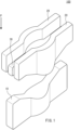
- FIG. 1 is a perspective view showing a schematic configuration of a press forming apparatus according to a first embodiment.
- FIG. 2 is a cross-sectional view of the press molding apparatus shown in FIG.
- FIG. 3 is a plan view of the press molding apparatus shown in FIG.
- FIG. 4 is a side view of the press molding apparatus shown in FIG.
- FIG. 5A is a schematic diagram for explaining the method for manufacturing a press-formed product according to the first embodiment.
- FIG. 5B is a schematic diagram for explaining the method for manufacturing a press-formed product according to the first embodiment.
- FIG. 5C is a schematic diagram for explaining the manufacturing method of the press-formed product according to the first embodiment.
- FIG. 5D is a schematic diagram for explaining the method for manufacturing a press-formed product according to the first embodiment.
- FIG. 5A is a schematic diagram for explaining the method for manufacturing a press-formed product according to the first embodiment.
- FIG. 5B is a schematic diagram for explaining the method for manufacturing a press-formed product
- FIG. 6 is a perspective view showing an example of the press-formed product according to the first embodiment.
- FIG. 7 is a plan view of a punch according to a modified example of the first embodiment.
- FIG. 8 is a plan view of a punch according to another modified example of the first embodiment.
- FIG. 9 is a plan view of a punch according to still another modified example of the first embodiment.
- FIG. 10 is a plan view of a punch according to still another modified example of the first embodiment.
- FIG. 11 is a plan view of a punch according to still another modified example of the first embodiment.
- FIG. 12 is a plan view of a punch according to still another modified example of the first embodiment.
- FIG. 13 is a side view of the punch shown in FIGS. FIG.
- FIG. 14 is a perspective view showing a schematic configuration of a press forming apparatus according to the second embodiment.
- FIG. 15 is a cross-sectional view of the press molding apparatus shown in FIG.
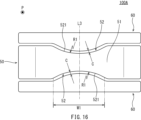
- FIG. 16 is a plan view of the press molding apparatus shown in FIG.
- FIG. 17 is a side view of the press molding apparatus shown in FIG.
- FIG. 18A is a schematic diagram for explaining the manufacturing method of a press-formed product according to the second embodiment.
- FIG. 18B is a schematic diagram for explaining the manufacturing method of a press-formed product according to the second embodiment.
- FIG. 18C is a schematic diagram for explaining the manufacturing method of a press-formed product according to the second embodiment.
- FIG. 18D is a schematic diagram for explaining the manufacturing method of a press-formed product according to the second embodiment.
- FIG. 18A is a schematic diagram for explaining the manufacturing method of a press-formed product according to the second embodiment.
- FIG. 18B is a schematic diagram for explaining the manufacturing method of a press-formed product
- FIG. 19 is a perspective view showing an example of a press-formed product according to the second embodiment.
- FIG. 20 is a plan view of a punch according to a modified example of the second embodiment.
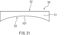
- FIG. 21 is a plan view of a punch according to another modified example of the second embodiment.
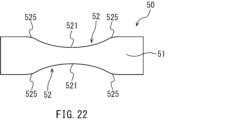
- FIG. 22 is a plan view of a punch according to still another modified example of the second embodiment.
- FIG. 23 is a plan view of a punch according to still another modified example of the second embodiment.
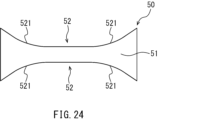
- FIG. 24 is a plan view of a punch according to still another modified example of the second embodiment.
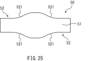
- FIG. 25 is a plan view of a punch according to still another modified example of the second embodiment.
- FIG. 26 is a side view of the punch shown in FIGS. 24 and 25.
- FIG. 27 is a partial perspective view of a punch according to still another modified example of the second embodiment.
- FIG. 28 is a graph showing the damage values for each example.
- the press forming device includes a punch and a die.
- the die moves relative to the punch in the press direction.
- the punch includes a punch top surface, a punch shoulder, and a punch side surface.
- the punch top surface intersects with the press direction.
- the punch shoulder is continuous with the punch top surface.
- the punch side surface is continuous with the punch shoulder.
- the punch side surface is connected to the punch top surface via the punch shoulder.
- the punch shoulder includes a curved portion. The curved portion is curved convexly toward the outside of the punch when viewed from the press direction, and curved concavely toward the inside of the punch when viewed from the punch side surface.
- the curved portion is curved concavely toward the inside of the punch when viewed from the press direction, and curved convexly toward the outside of the punch when viewed from the punch side surface.
- the curved portion extends with a radius of curvature of 5 mm or more and 400 mm or less when viewed from the punch side surface (first configuration).
- the punch shoulder includes a curved portion.
- the curved portion is, for example, curved concavely toward the inside of the punch when viewed from the side of the punch, and extends with a radius of curvature of 400 mm or less. Therefore, when the blank is formed into a press-formed product by the punch and the die, stretch flange deformation occurs at the end of the blank bent along the curved portion of the punch shoulder.
- the curved portion is curved concavely toward the inside of the punch when viewed from the side of the punch, it is curved convexly toward the outside of the punch when viewed from the press direction.
- shrink flange deformation also occurs at the end of the blank bent along the curved portion of the punch shoulder. Therefore, both elongation and shrinkage occur at the end of the blank near the curved portion, and the elongation is offset by the shrinkage. Therefore, even if the punch shoulder is provided with a concave curved portion extending with a radius of curvature of 400 mm or less when viewed from the side of the punch, the occurrence of breakage of the blank due to stretch flange deformation can be suppressed in the manufacture of press-formed products.
- the curved portion of the punch shoulder may be curved convexly toward the outside of the punch when viewed from the side of the punch.
- the curved portion is curved concavely toward the inside of the punch when viewed from the press direction.
- stretch flange deformation occurs at the end of the blank bent along the curved portion of the punch shoulder when the blank is formed into a press-formed product by the punch and die.
- shrink flange deformation also occurs at the end of the blank near the curved portion.
- the press forming device according to the first configuration can further include a pad facing the top surface of the punch (second configuration).
- the blank can be formed by the punch and die while the blank is clamped between the punch top surface and the pad. This makes it difficult for wrinkles to form in the blank, and allows the press-formed product to be formed from the blank with high precision.
- R1/ R2 is 0.017 or more and smaller than 0.622 (third configuration).
- the ratio R1/R22 between the radius of curvature R1 of the curved portion of the punch shoulder as viewed from the press direction and the square of the radius of curvature R2 of the curved portion as viewed from the punch side is set to 0.017 or more and less than 0.622.
- the elongation and contraction of the end of the blank near the curved portion are more effectively offset. Therefore, the blank breakage caused by stretch flange deformation is less likely to occur.
- the punch shoulder and punch side surface when viewed from the pressing direction, may be provided on both sides of the punch top surface (fourth configuration).
- the punch shoulder provided on one side of the punch top surface may be symmetrical with the punch shoulder provided on the other side of the punch top surface (fifth configuration).
- the press-formed product according to the embodiment includes a top plate, a ridge portion, and a vertical wall.
- the ridge portion is continuous with the top plate.
- the vertical wall is continuous with the ridge portion.
- the vertical wall is connected to the top plate via the ridge portion.
- the ridge portion includes a curved portion.
- the curved portion is curved convexly toward the outside of the press-formed product when viewed from the top plate side, and curved concavely toward the inside of the press-formed product when viewed from the vertical wall side.
- the curved portion is curved concavely toward the inside of the press-formed product when viewed from the top plate side, and curved convexly toward the outside of the press-formed product when viewed from the vertical wall side.
- the curved portion extends with a radius of curvature of 5 mm or more and 400 mm or less when viewed from the vertical wall side (sixth configuration).
- Some structural components of automobiles have ridges that are curved concavely in side view, such as the rear upper arms of a multi-link suspension.
- the bottom of the concave curved shape is required to be the most durable.
- the press-formed product of the sixth configuration when the curved portion of the ridge is concave in side view, the curved portion is convex in plan view. Therefore, the section modulus of the press-formed product can be increased at the bottom of the curved portion, thereby improving the strength.
- This press-formed product can therefore be suitably used as a structural component of an automobile.
- the press-formed product can be manufactured more easily than with conventional methods, for example, by using the press-forming device described above.
- the curved portion of the ridge line may be convex in side view.
- the bending strength of the top of the curved portion can be improved. Therefore, this press-formed product can be suitably used as a body part that bridges between components, such as a roof rail.
- the manufacturing method of the press-formed product according to the embodiment includes a step of placing a blank between a punch and a die, and a step of bringing the punch and the die relatively close to each other in the press direction and pressing the blank with the punch and the die.
- the punch includes a punch top surface, a punch shoulder, and a punch side surface.
- the punch top surface intersects with the press direction.
- the punch shoulder is continuous with the punch top surface.
- the punch side surface is continuous with the punch shoulder.
- the punch side surface is connected to the punch top surface via the punch shoulder.
- the punch shoulder includes a curved portion.
- the curved portion is curved convexly toward the outside of the punch when viewed from the press direction, and curved concavely toward the inside of the punch when viewed from the punch side surface.
- the curved portion is curved concavely toward the inside of the punch when viewed from the press direction, and curved convexly toward the outside of the punch when viewed from the punch side surface.
- the curved portion extends with a radius of curvature of 5 mm or more and 400 mm or less when viewed from the punch side surface (seventh configuration).
- Fig. 1 is a perspective view showing a schematic configuration of a press molding apparatus 100 according to a first embodiment.
- the press molding apparatus 100 includes a punch 10, a die 20, and a pad 30.
- the die 20 is disposed on both sides of the punch 10. These dies 20 may be separate bodies or may be formed integrally.
- the pad 30 is disposed between the dies 20.
- the die 20 and pad 30 are configured to be movable relative to the punch 10 in the press direction P.
- the punch 10 may be moved in the press direction P, or the die 20 and pad 30 may be moved in the press direction P, by a drive mechanism (not shown) such as a fluid pressure cylinder.
- a drive mechanism such as a fluid pressure cylinder.
- the press direction P is, for example, a vertical direction.
- FIG. 2 is a cross-sectional view of the press forming apparatus 100.
- the cross-sectional view of the press forming apparatus 100 is a cross-section of the press forming apparatus 100 cut in a plane perpendicular to the longitudinal direction of the punch 10 and the die 20.
- FIG. 3 is a view (plan view) of the press forming apparatus 100 as seen from the pressing direction P.
- FIG. 3 shows the press forming apparatus 100 projected onto a plane perpendicular to the pressing direction P.
- FIG. 4 is a side view of the press forming apparatus 100.
- the pad 30 is omitted in FIGS. 3 and 4.
- the configuration of the press forming apparatus 100 will be described in detail below with reference to FIGS. 2 to 4.
- punch 10 As shown in FIG. 2, punch 10 includes a top punch surface 11 , two punch shoulders 12 , and two punch sides 13 .
- the punch top surface 11 intersects with the press direction P.
- the punch shoulder 12 and the punch side surface 13 are provided on both sides of the punch top surface 11.
- Each of the punch shoulders 12 is continuous with the punch top surface 11.
- Each of the punch side surfaces 13 is continuous with the punch shoulder 12.
- the punch side surfaces 13 are connected to the punch top surface 11 via the punch shoulder 12 so as to bend in the press direction P relative to the punch top surface 11.
- the punch shoulder 12 may have a substantially arc shape in a cross-sectional view of the press forming apparatus 100.
- the punch shoulder 12 and the punch side surfaces 13 extend along the punch top surface 11.
- each of the punch shoulders 12 includes a curved portion 121. That is, punch shoulders 12 including curved portions 121 are provided on both sides of the punch top surface 11. When viewed from the press direction P, the curved portions 121 are curved convexly outward from the punch 10. When viewed from the press direction P, the curved portions 121 have, for example, a curved shape that is convex outward in the width direction of the punch 10. In the example of this embodiment, when viewed from the press direction P, the curved portions 121 are symmetrical with respect to an imaginary straight line L1 that extends in the width direction of the punch 10. When viewed from the press direction P, the punch top surface 11 and punch side surface 13 ( FIG. 2 ) include portions that bulge outward from the punch 10 in response to the curved portions 121 of the punch shoulders 12.
- the curved portion 121 When viewed from the press direction P, the curved portion 121 extends with a radius of curvature of, for example, 400 mm or less. When viewed from the press direction P, the curved portion 121 may extend with a radius of curvature of 5 mm or more, or may extend with a radius of curvature of 10 mm or more. When viewed from the press direction P, the curved portion 121 may extend with a constant radius of curvature throughout, or the radius of curvature may change along the extension direction.
- the radius of curvature of an arc passing through three points, including each point and two adjacent points arranged at 5 mm intervals on the edge of the punch shoulder 12 on the die 20 side, can be measured, and the section with a radius of curvature of 400 mm or less can be defined as the curved portion 121.
- the average value of the radii of curvature measured at 5 mm intervals in this way can be defined as the radius of curvature R1 of the curved portion 121 when viewed from the press direction P.
- the curved portion 121 is curved concavely toward the inside of the punch 10 when viewed from the punch side surface 13 side.
- the curved portion 121 has a curved shape that is concave toward the side opposite the die 20 when viewed from the side of the press forming device 100. It is preferable that the position of the curved bottom of the curved portion 121 when viewed from the punch side surface 13 side substantially coincides with the position of the curved apex of the curved portion 121 when viewed from the press direction P (FIG. 3).
- the curved bottom of the curved portion 121 when viewed from the punch side surface 13 side is located within a range of 0 mm to 100 mm in the extension direction of the punch shoulder 12 from the curved apex of the curved portion 121 when viewed from the press direction P.
- the curved apex is the portion of the curved portion 121 that is located most outside the punch 10 when viewed from the press direction P.
- the curved bottom is the portion of the curved portion 121 that is located most inside the punch 10 when viewed from the punch side surface 13 side.
- the curved portion 121 when viewed from the punch side surface 13 side, the curved portion 121 is provided in the concave portion 122.
- the concave portion 122 is a portion of the punch shoulder 12 that is concave toward the opposite side of the die 20 compared to the other portions.
- the concave portion 122 is symmetrical with respect to an imaginary straight line L2 extending in the press direction P when viewed from the punch side surface 13 side.
- the punch top surface 11 ( Figure 2) includes a portion that corresponds to the concave portion 122 of the punch shoulder 12 and is concave in the press direction P toward the opposite side of the die 20.
- the concave portion 122 includes straight portions 123 and 124 in addition to the curved portion 121.
- the curved portion 121 extends with a radius of curvature of 5 mm or more and 400 mm or less.
- the curved portion 121 may extend with a radius of curvature of 10 mm or more.
- the curved portion 121 may extend with a constant radius of curvature throughout, or the radius of curvature may change along the extension direction.
- the straight portions 123 and 124 When viewed from the punch side surface 13 side, the straight portions 123 and 124 are continuous with both ends of the curved portion 121 and extend so as to move away from each other as they move away from the curved portion 121.
- the straight portions 123 and 124 may be located on the tangents (two-dot chain lines in FIG. 4) at both ends of the curved portion 121.
- Each of the straight portions 123, 124 has a substantially straight line shape when viewed from the punch side surface 13 side.
- the radius of curvature of an arc passing through three points that is, the points arranged at 5 mm intervals on the edge of the punch shoulder 12 on the die 20 side and the points located on both sides of the point, can be measured, and the section where the radius of curvature is 400 mm or less can be defined as the curved portion 121, and the section where the radius of curvature is greater than 400 mm can be defined as the non-curved portion (straight portion).
- the average value of the radii of curvature measured at 5 mm intervals in this way can be defined as the radius of curvature R2 of the curved portion 121 when viewed from the punch side surface 13 side.
- the radius of curvature R2 may be equal to or different from the radius of curvature R1 (FIG. 3) of the curved portion 121 when viewed from the press direction P.
- the angle formed by the tangents at both ends of the curved portion 121 when viewed from the punch side surface 13 side can be defined as the included angle ⁇ of the curved portion 121.
- the included angle ⁇ is less than 180°.
- the included angle ⁇ may be, for example, greater than or equal to 60° and less than or equal to 120°.
- the ratio R1/R22 of the radius of curvature R1 (FIG. 3) of the curved portion 121 when viewed from the press direction P to the square of the radius of curvature R2 (FIG. 4) of the curved portion 121 when viewed from the punch side surface 13 is preferably 0.017 or more.
- R1/ R22 is preferably smaller than 0.622.
- the width W2 (FIG. 4) of the curved portion 121 when viewed from the punch side 13 side is, for example, 10% or more, and preferably 20% or more, of the width W1 (FIG. 3) of the curved portion 121 when viewed from the press direction P.
- the width W2 of the curved portion 121 when viewed from the punch side 13 side may be 200% or less, and preferably is 100% or less, of the width W1 of the curved portion 121 when viewed from the press direction P.
- the width W1 of the curved portion 121 is the straight-line distance between both ends of the curved portion 121 when viewed from the press direction P, specifically, between both ends of a section extending with a radius of curvature of 400 mm or less when viewed from the press direction P.
- the width W2 of the curved portion 121 is the straight-line distance between both ends of the curved portion 121 when viewed from the punch side 13 side, specifically, between both ends of a section extending with a radius of curvature of 400 mm or less when viewed from the punch side 13 side.
- each of the dies 20 includes a pressure surface 21, a die shoulder 22, and a die side 23.
- the pressing surface 21 is a surface for pressing the blank during press forming.
- the pressing surface 21 intersects with the press direction P.
- the pressing surface 21 is a surface facing opposite to the punch top surface 11.
- the die shoulder 22 is continuous with the pressing surface 21.
- the die side surface 23 is continuous with the die shoulder 22.
- the die side surface 23 is connected to the pressing surface 21 via the die shoulder 22 so as to bend in the press direction P relative to the pressing surface 21.
- the die shoulder 22 may have a substantially arc shape, for example, when viewed in a cross section of the press forming apparatus 100.
- the die shoulder 22 and the die side surface 23 extend along the pressing surface 21.
- the die 20 has a shape corresponding to the punch 10. As shown in FIG. 3, when viewed from the press direction P, the edge of the die 20 on the punch 10 side extends along the edge of the punch 10 on the die 20 side. When viewed from the press direction P, a clearance C exists between the die 20 and the punch 10.
- the clearance C can be equal to or greater than the plate thickness of the blank, which is the material for press forming.
- the clearance C is constant throughout the die 20, for example, in the extension direction of the punch shoulder 12. However, the clearance C may change along the extension direction of the punch shoulder 12.
- the edge of the die 20 on the punch 10 side extends along the edge of the punch 10 on the die 20 side.
- the edge of the die 20 on the punch 10 side is, for example, generally parallel to the edge of the punch 10 on the die 20 side.
- at least a portion of the edge of the die 20 does not have to be parallel to the edge of the punch 10.
- the die 20 is formed in a shape corresponding to the punch 10 so that the die side surface 23 (FIG. 2) can clamp the blank together with the punch side surface 13.
- the pad 30 faces the punch top surface 11.
- the pad 30 is disposed between the two dies 20.
- the pad 30 moves relative to each of the dies 20 in the pressing direction P by an elastic member 40 such as a fluid pressure cylinder or a spring.
- the pad 30 includes a pressing surface 31.
- the pressing surface 31 is a surface for pressing the blank during press forming.
- the pressing surface 31 faces the punch top surface 11 in the press direction P.
- the pressing surface 31 has a shape corresponding to the punch top surface 11. In other words, the pressing surface 31 of the pad 30 is formed into a shape that engages with the punch top surface 11 so that the blank can be clamped between the pressing surface 31 and the punch top surface 11.
- the method for manufacturing a press-formed product includes a step of placing a blank 200 between a punch 10 and a die 20, and a step of bringing the punch 10 and the die 20 relatively close to each other in a press direction P and pressing the blank 200 with the punch 10 and the die 20.
- a blank 200 is prepared.
- the blank 200 can be obtained, for example, by blanking a metal strip.
- the blank 200 is formed, for example, into a shape obtained by unfolding the desired press-formed product.
- the blank 200 may be a steel plate.
- the blank 200 is preferably a high-tensile steel plate.
- the tensile strength of the blank 200 is, for example, 440 MPa or more.
- the tensile strength of the blank 200 may be 590 MPa or more, or 780 MPa or more.
- the tensile strength of the blank 200 may be 1300 MPa or more.
- the plate thickness of the blank 200 is, for example, 0.4 mm or more and 6.0 mm or less.
- the blank 200 is placed between the punch 10 and the die 20 and pad 30.
- the blank 200 is placed on the punch top surface 11.
- the blank 200 may be placed on the pressing surface 21 of the die 20.
- the die 20 and pad 30 are brought relatively close to the punch 10 in the press direction P. This causes the blank 200 to be pressed by the pressing surface 31 of the pad 30. The blank 200 is clamped between the punch top surface 11 and the pressing surface 31 of the pad 30.
- FIG. 5C shows an example in which forming is completed after the blank 200 has been completely pulled out from the pressing surface 21 side of the die 20.
- FIG. 5D is a diagram illustrating a press-formed product 300 manufactured by the manufacturing method according to this embodiment.
- the press-formed product 300 is typically used as a structural member of an automobile.
- the press-formed product 300 is used, for example, as a chassis part of an automobile.
- the press-formed product 300 may be a link part, which is a type of chassis part.
- the press-formed product 300 may be used as a reinforcement that reinforces other parts.
- the press-formed product 300 comprises a top plate 301, two ridge portions 302, and two vertical walls 303.
- the ridge portions 302 are continuous with the top plate 301 and extend along both side edges of the top plate 301.
- Each of the vertical walls 303 is continuous with the ridge portions 302.
- Each vertical wall 303 is connected to the top plate 301 via the ridge portions 302.
- Each vertical wall 303 extends along the ridge portions 302.
- Each of the ridges 302 includes a curved portion 302a corresponding to the curved portion 121 (FIGS. 3 and 4) of the punch shoulder 12. That is, the ridges 302 including the curved portion 302a are provided on both sides of the top plate 301.
- the curved portion 302a is curved convexly toward the outside of the press-formed product 300 when viewed from the top plate 301 side (when viewed from above the press-formed product 300). More specifically, the curved portion 302a has a curved shape that is convex toward the outside of the press-formed product 300 in a direction that intersects with the ridge portion 302 when viewed from above the press-formed product 300.
- the curved portion 302a is curved concavely toward the inside of the press-formed product 300 when viewed from the vertical wall 303 side (when viewed from the side of the press-formed product 300). When the top plate 301 side is viewed from above, the curved portion 302a is curved downward when viewed from the side of the press-formed product 300.
- the curved portion 302a extends with a radius of curvature of 5 mm or more and 400 mm or less when viewed from the vertical wall 303 side.
- the curved portion 302a may extend with a radius of curvature of 10 mm or more when viewed from the vertical wall 303 side.
- the curved portion 302a can extend with a radius of curvature of 400 mm or less when viewed from the top plate 301 side.
- the curved portion 302a may extend with a radius of curvature of 5 mm or more and may extend with a radius of curvature of 10 mm or more when viewed from the top plate 301 side.
- the radius of curvature of the curved portion 302a can be measured in the same manner as the curved portion 121 of the punch shoulder 12.
- the relationship between the radius of curvature of the curved portion 302a in a plan view of the press-formed product 300 and the radius of curvature of the curved portion 302a in a side view of the press-formed product 300 is similar to the relationship between the radius of curvature R1 and the radius of curvature R2 of the curved portion 121 of the punch shoulder 12 ( Figures 3 and 4).
- the ratio of the radius of curvature of the curved portion 302a in a plan view of the press-formed product 300 to the square of the radius of curvature of the curved portion 302a in a side view of the press-formed product 300 is, for example, 0.017 or more and less than 0.622.
- FIG. 6 is a diagram showing a modified example of the press-formed product 300 shown in FIG. 5D.
- the press-formed product 300 may further include two flanges 304.
- Each flange 304 is continuous with the vertical wall 303 and protrudes from the vertical wall 303 toward the outside of the press-formed product 300.
- the press-forming device 100 (FIGS. 1 to 4) may include a blank holder (not shown) corresponding to each die 20. The blank holder can clamp the end of the blank 200 together with the pressing surface 21 of the die 20.
- the press-formed product 300 including the flanges 304 can be manufactured by completing the forming in a state in which the end of the blank 200 remains between the pressing surface 21 of the die 20 and the blank holder. However, even if the press-forming device 100 includes a blank holder, the forming can be completed after the end of the blank 200 is completely pulled out from between the pressing surface 21 of the die 20 and the blank holder.
- the punch shoulder 12 includes a curved portion 121.
- the curved portion 121 is curved concavely toward the inside of the punch 10 when viewed from the punch side surface 13 side, and extends with a radius of curvature of 400 mm or less. Therefore, when the blank 200 is formed into the press-formed product 300 by the punch 10 and the die 20, stretch flange deformation occurs at the end of the blank 200 bent along the curved portion 121.
- the curved portion 121 is curved convexly toward the outside of the punch 10 when viewed from the press direction P.
- cracks caused by stretch flange deformation and forming defects caused by shrink flange deformation are suppressed by devising the shape of the punch 10. Therefore, for the purpose of suppressing cracks caused by stretch flange deformation or forming defects caused by shrink flange deformation, for example, there is no need to perform pre-forming on the blank 200. Therefore, it is possible to easily manufacture the press-formed product 300 while suppressing cracks caused by stretch flange deformation and forming defects caused by shrink flange deformation.
- the position of the bottom of the curve of the curved portion 121 of the punch shoulder 12 when viewed from the punch side surface 13 side substantially coincides with the position of the apex of the curve of the curved portion 121 of the punch shoulder 12 when viewed from the press direction P.
- the part where noticeable shrinkage occurs due to the curved portion 121 that is convex when viewed from the press direction P corresponds to the part where noticeable elongation occurs due to the curved portion 121 that is concave when viewed from the punch side surface 13 side, and the elongation and shrinkage of the blank 200 are effectively offset. Therefore, breakage of the blank 200 due to stretch flange deformation and molding defects such as wrinkles due to shrink flange deformation are more easily suppressed.
- the ratio R1/R22 of the radius of curvature R1 of the curved portion 121 of the punch shoulder 12 when viewed from the press direction P to the square of the radius of curvature R2 of the curved portion 121 when viewed from the punch side surface 13 is preferably set to 0.017 or more and less than 0.622.
- the elongation and contraction of the blank 200 in the vicinity of the curved portion 121 are easily offset. Therefore, cracks due to stretch flange deformation and forming defects due to shrink flange deformation are less likely to occur.
- the punch 10 can take on various shapes.
- Figures 7 to 12 are plan views of the punch 10 according to modified examples of this embodiment.
- a portion of the punch shoulder 12 is the curved portion 121 when viewed from the press direction P, but as shown in Figure 7, the entire punch shoulder 12 may be the curved portion 121 when viewed from the press direction P.
- only one of the two punch shoulders 12 of the punch 10 may include the curved portion 121.
- the punch shoulder 12 can include another curved portion 125 in addition to the curved portion 121.
- the curved portions 125 when viewed from the press direction P, are provided continuously on both sides of the curved portion 121.
- Each of the curved portions 125 is curved in the opposite direction to the curved portion 121.
- Each of the curved portions 125 is curved concavely toward the inside of the punch 10 when viewed from the press direction P.
- the punch shoulder 12 can also include straight portions 126, 127 when viewed from the press direction P.
- the straight portions 126, 127 are provided continuously on both sides of the curved portion 121 when viewed from the press direction P.
- Each of the straight portions 126, 127 has a substantially linear shape when viewed from the press direction P.
- the punch shoulder 12 can have a shape similar to the punch shoulder 12 shown in Figure 4 when viewed from the punch side surface 13 side. That is, the curved portion 121 of the punch shoulder 12 is curved concavely toward the inside of the punch 10 when viewed from the punch side surface 13 side.
- each punch shoulder 12 of the punch 10 includes a single curved portion 121.
- the punch shoulder 12 can also include multiple curved portions 121.
- two curved portions 121 are provided on each punch shoulder 12.
- each curved portion 121 is curved convexly toward the outside of the punch 10.
- each curved portion 121 is curved concavely toward the inside of the punch 10.
- the press-formed product 300 includes a curved portion 302a at the ridge portion 302.
- the curved portion 302a is concave in a side view of the press-formed product 300, but is convex in a plan view of the press-formed product 300. Therefore, at the bottom of the concave curved portion 302a in a side view, the section modulus of the press-formed product 300 can be increased to improve the strength.
- Such a press-formed product 300 can be suitably used as a link part such as a rear upper arm in a multi-link suspension. By using the press-forming device 100, the press-formed product 300 can be manufactured more easily than by conventional methods.
- Fig. 14 is a perspective view showing a schematic configuration of a press molding apparatus 100A according to the second embodiment.
- the press molding apparatus 100A includes a punch 50, a die 60, and a pad 70.
- the die 60 is disposed on both sides of the punch 50. These dies 60 may be separate bodies or may be formed integrally.
- the pad 70 is disposed between the dies 60. As in the first embodiment, the die 60 and the pad 70 move relatively to the punch 50 in the pressing direction P.
- FIG. 15 is a cross-sectional view (transverse cross-sectional view) of the press molding apparatus 100A cut along a plane perpendicular to the longitudinal direction of the punch 50 and the die 60.
- FIG. 16 is a view (plan view) of the press molding apparatus 100A as seen from the press direction P.
- FIG. 16 shows the press molding apparatus 100A projected onto a plane perpendicular to the press direction P.
- FIG. 17 is a side view of the press molding apparatus 100A.
- the pad 70 is omitted in FIGS. 16 and 17.
- the configuration of the press molding apparatus 100A will be described in detail below with reference to FIGS. 15 to 17.
- punch 50 includes a punch top surface 51 , two punch shoulders 52 , and two punch sides 53 .
- the punch top surface 51 intersects with the press direction P.
- the punch shoulder 52 and the punch side surface 53 are provided on both sides of the punch top surface 51.
- Each of the punch shoulders 52 is continuous with the punch top surface 51.
- Each of the punch side surfaces 53 is continuous with the punch shoulder 52.
- the punch side surfaces 53 are connected to the punch top surface 51 via the punch shoulder 52 so as to bend in the press direction P relative to the punch top surface 51.
- the punch shoulder 52 may have a substantially arc shape in a cross-sectional view of the press forming apparatus 100A.
- the punch shoulder 52 and the punch side surfaces 53 extend along the punch top surface 51.
- each of the punch shoulders 52 includes a curved portion 521. That is, punch shoulders 52 including curved portions 521 are provided on both sides of the punch top surface 51.
- the curved portions 521 are curved concavely toward the inside of the punch 50 when viewed from the press direction P.
- the curved portions 521 have, for example, a curved shape that is concave toward the inside in the width direction of the punch 50.
- the curved portions 521 are symmetrical with respect to an imaginary straight line L3 that extends in the width direction of the punch 50 when viewed from the press direction P.
- the punch top surface 51 and punch side surface 53 include portions that are recessed toward the inside of the punch 50 in response to the curved portions 521 of the punch shoulders 52.
- the curved portion 521 When viewed from the press direction P, the curved portion 521 extends with a radius of curvature of, for example, 400 mm or less. When viewed from the press direction P, the curved portion 521 may extend with a radius of curvature of 5 mm or more, or may extend with a radius of curvature of 10 mm or more. When viewed from the press direction P, the curved portion 521 may extend with a constant radius of curvature over the entire portion, or the radius of curvature may change along the extension direction.
- the radius of curvature of an arc passing through three points, that is, the points and the two adjacent points, placed at 5 mm intervals on the edge of the punch shoulder 52 on the die 60 side can be measured, and the section with a radius of curvature of 400 mm or less can be defined as the curved portion 521.
- the average value of the radii of curvature measured at 5 mm intervals in this way can be defined as the radius of curvature R1 of the curved portion 521 when viewed from the press direction P.
- the curved portion 521 is curved convexly toward the outside of the punch 50 when viewed from the punch side surface 53 side.
- the curved portion 521 has a curved shape that is convex toward the die 60 side when viewed from the side of the press forming device 100A. It is preferable that the position of the curved apex of the curved portion 521 when viewed from the punch side surface 53 side substantially coincides with the position of the curved bottom of the curved portion 521 when viewed from the press direction P (FIG. 16).
- the curved apex of the curved portion 521 when viewed from the punch side surface 53 side is located within a range of 0 mm to 100 mm in the extension direction of the punch shoulder 52 from the curved bottom of the curved portion 521 when viewed from the press direction P.
- the curved apex is the portion of the curved portion 521 that is located most outside the punch 50 when viewed from the punch side surface 53 side.
- the curved bottom is the portion of the curved portion 521 that is located most inside the punch 50 when viewed from the press direction P.
- the curved portion 521 is provided on the convex portion 522.
- the convex portion 522 is a portion of the punch shoulder 52 that protrudes toward the die 60 side compared to other portions.
- the convex portion 522 is symmetrical with respect to an imaginary straight line L4 extending in the press direction P when viewed from the punch side surface 53 side.
- the punch top surface 51 ( Figure 15) includes a portion that protrudes in the press direction P toward the die 60 side, corresponding to the convex portion 522 of the punch shoulder 52.
- the convex portion 522 includes straight portions 523 and 524 in addition to the curved portion 521.
- the curved portion 521 extends with a radius of curvature of 5 mm or more and 400 mm or less.
- the curved portion 521 may extend with a radius of curvature of 10 mm or more.
- the curved portion 521 may extend with a constant radius of curvature throughout, or the radius of curvature may change along the extension direction.
- the straight portions 523 and 524 When viewed from the punch side surface 53 side, the straight portions 523 and 524 are continuous with both ends of the curved portion 521 and extend so as to move away from each other as they move away from the curved portion 521.
- the straight portions 523 and 524 may be located on the tangents (two-dot chain lines in FIG. 17) at both ends of the curved portion 521.
- Each of the straight portions 523, 524 has a substantially straight line shape when viewed from the punch side surface 53 side.
- the radius of curvature of an arc passing through three points that is, the point and the two adjacent points located on each side of the edge of the punch shoulder 52 on the die 60 side, arranged at 5 mm intervals, can be measured, and the section where the radius of curvature is 400 mm or less can be defined as the curved portion 521, and the section where the radius of curvature is greater than 400 mm can be defined as the non-curved portion (straight portion).
- the average value of the radii of curvature measured at 5 mm intervals in this way can be defined as the radius of curvature R2 of the curved portion 521 when viewed from the punch side surface 53 side.
- the radius of curvature R2 may be equal to or different from the radius of curvature R1 (FIG. 16) of the curved portion 521 when viewed from the press direction P.
- the angle formed by the tangents at both ends of the curved portion 521 when viewed from the punch side surface 53 side can be defined as the included angle ⁇ of the curved portion 521.
- the included angle ⁇ is less than 180°.
- the included angle ⁇ may be, for example, greater than or equal to 60° and less than or equal to 120°.
- each of the dies 60 includes a pressure surface 61 , a die shoulder 62 , and a die side 63 .
- the pressing surface 61 is a surface for pressing the blank during press forming.
- the pressing surface 61 intersects with the press direction P.
- the pressing surface 61 is a surface facing opposite to the punch top surface 51.
- the die shoulder 62 is continuous with the pressing surface 61.
- the die side surface 63 is continuous with the die shoulder 62.
- the die side surface 63 is connected to the pressing surface 61 via the die shoulder 62 so as to bend in the press direction P relative to the pressing surface 61.
- the die shoulder 62 may have a substantially arc shape, for example, when viewed in a cross section of the press forming apparatus 100A.
- the die shoulder 62 and the die side surface 63 extend along the pressing surface 61.
- the die 60 has a shape corresponding to the punch 50. As shown in FIG. 16, when viewed from the press direction P, the edge of the die 60 on the punch 50 side extends along the edge of the punch 50 on the die 60 side. When viewed from the press direction P, a clearance C exists between the die 60 and the punch 50.
- the clearance C can be equal to or greater than the plate thickness of the blank, which is the material for press forming.
- the clearance C is constant throughout the die 60, for example, in the extension direction of the punch shoulder 52. However, the clearance C may change along the extension direction of the punch shoulder 52.
- the edge of the die 60 on the punch 50 side extends along the edge of the punch 50 on the die 60 side.
- the edge of the die 60 on the punch 50 side is, for example, generally parallel to the edge of the punch 50 on the die 60 side.
- at least a portion of the edge of the die 60 does not have to be parallel to the edge of the punch 50.
- the die 60 is formed in a shape corresponding to the punch 50 so that the die side 63 (FIG. 15) can clamp the blank together with the punch side 53.
- the pad 70 includes a pressing surface 71.
- the pressing surface 71 is a surface for pressing the blank during press forming.
- the pressing surface 71 faces the punch top surface 51 in the press direction P.
- the pressing surface 71 has a shape corresponding to the punch top surface 51. In other words, the pressing surface 71 of the pad 70 is formed into a shape that engages with the punch top surface 51 so that the blank can be clamped between the pressing surface 71 and the punch top surface 51.
- the blank 200 is placed between the punch 50 and the die 60 and pad 70.
- the blank 200 is placed on the punch top surface 51.
- the blank 200 may be placed on the pressing surface 61 of the die 60.
- the die 60 and pad 70 are brought relatively close to the punch 50 in the press direction P. This causes the blank 200 to be pressed by the pressing surface 71 of the pad 70. The blank 200 is clamped between the punch top surface 51 and the pressing surface 71 of the pad 70.
- FIG. 18D is a diagram illustrating a press-formed product 400 manufactured by the manufacturing method according to this embodiment.
- the press-formed product 400 is typically used as a structural member of an automobile.
- the press-formed product 400 is used, for example, as a chassis part of an automobile.
- the press-formed product 400 may be a link part, which is a type of chassis part.
- the press-formed product 400 may be used as a reinforcement that reinforces other parts.
- the press-molded product 400 comprises a top plate 401, two ridge portions 402, and two vertical walls 403.
- the ridge portions 402 are continuous with the top plate 401 and extend along both side edges of the top plate 401.
- Each of the vertical walls 403 is continuous with the ridge portions 402.
- Each vertical wall 403 is connected to the top plate 401 via the ridge portions 402.
- Each vertical wall 403 extends along the ridge portions 402.
- the curved portion 402a is curved convexly toward the outside of the press-formed product 400 when viewed from the vertical wall 403 side (when viewed from the side of the press-formed product 400).
- the curved portion 402a is curved upward when viewed from the side of the press-formed product 400.
- the curved portion 402a extends with a radius of curvature of 5 mm or more and 400 mm or less when viewed from the vertical wall 403 side.
- the curved portion 402a may extend with a radius of curvature of 10 mm or more when viewed from the vertical wall 403 side.
- the curved portion 402a can extend with a radius of curvature of 400 mm or less when viewed from the top plate 401 side.
- the curved portion 402a may extend with a radius of curvature of 5 mm or more and may extend with a radius of curvature of 10 mm or more when viewed from the top plate 401 side.
- the radius of curvature of the curved portion 402a can be measured in the same manner as the curved portion 521 of the punch shoulder 52.
- the press-formed product 400 may further include two flanges 404.
- Each flange 404 is continuous with the vertical wall 403 and protrudes from the vertical wall 403 toward the outside of the press-formed product 400.
- the press-forming device 100A may include a blank holder (not shown) corresponding to each die 60. The blank holder can clamp the end of the blank 200 together with the pressing surface 61 of the die 60.
- the press-formed product 400 including the flanges 404 can be manufactured by completing the forming in a state in which the end of the blank 200 remains between the pressing surface 61 of the die 60 and the blank holder. However, even if the press-forming device 100A includes a blank holder, the forming can be completed after the end of the blank 200 is completely pulled out from between the pressing surface 61 of the die 60 and the blank holder.
- the punch shoulder 52 includes a curved portion 521.
- the curved portion 521 is curved concavely toward the inside of the punch 50 when viewed from the press direction P. Therefore, when the blank 200 is formed into the press-formed product 400 by the punch 50 and the die 60, stretch flange deformation occurs at the end of the blank 200 bent along the curved portion 521.
- the curved portion 521 is curved convexly toward the outside of the punch 50. Therefore, when the blank 200 is formed into the press-formed product 400 by the punch 50 and the die 60, shrink flange deformation also occurs at the end of the blank 200 bent along the curved portion 521.
- both elongation and shrinkage occur at the end of the blank 200, and the elongation is offset by the shrinkage. Therefore, even if the concave curved portion 521 extends with a radius of curvature of 400 mm or less when viewed from the press direction P, breakage of the blank 200 due to stretch flange deformation is unlikely to occur in the production of the press-formed product 400.
- the expansion and contraction of the blank 200 are offset in the vicinity of the curved portion 521, so that molding defects such as wrinkles due to shrink flange deformation can also be suppressed.
- cracks caused by stretch flange deformation and forming defects caused by shrink flange deformation are suppressed by devising the shape of the punch 50. Therefore, for the purpose of suppressing cracks caused by stretch flange deformation or forming defects caused by shrink flange deformation, for example, there is no need to perform pre-forming on the blank 200. Therefore, it is possible to easily manufacture the press-formed product 400 while suppressing cracks caused by stretch flange deformation and forming defects caused by shrink flange deformation.
- the position of the curved apex of the curved portion 521 when viewed from the punch side surface 53 side substantially coincides with the position of the curved bottom of the curved portion 521 when viewed from the press direction P.
- a portion where significant elongation occurs due to the curved portion 521 that is concave when viewed from the press direction P corresponds to a portion where significant shrinkage occurs due to the curved portion 521 that is convex when viewed from the punch side surface 53 side, and the elongation and shrinkage of the blank 200 are effectively offset. Therefore, breakage of the blank 200 due to stretch flange deformation and molding defects such as wrinkles due to shrink flange deformation are more easily suppressed.
- the ratio R1/R22 of the radius of curvature R1 of the curved portion 521 of the punch shoulder 52 as viewed from the press direction P to the square of the radius of curvature R2 of the curved portion 521 as viewed from the punch side surface 53 is preferably set to 0.017 or more and less than 0.622.
- the elongation and contraction of the blank 200 in the vicinity of the curved portion 521 are easily offset. Therefore, cracks due to stretch flange deformation and forming defects due to shrink flange deformation are less likely to occur.
- the width W2 (FIG. 17) of the curved portion 521 when viewed from the punch side 53 side is, for example, 10% or more, and preferably 20% or more, of the width W1 (FIG. 16) of the curved portion 521 when viewed from the press direction P.
- the width W2 of the curved portion 521 when viewed from the punch side 53 side may be 200% or less, and preferably is 100% or less, of the width W1 of the curved portion 521 when viewed from the press direction P.
- the width W1 of the curved portion 521 is the straight-line distance between both ends of the curved portion 521 when viewed from the press direction P, specifically, between both ends of a section extending with a curvature radius of 400 mm or less when viewed from the press direction P.
- the width W2 of the curved portion 521 is the straight-line distance between both ends of the curved portion 521 when viewed from the punch side 53 side, specifically, between both ends of a section extending with a curvature radius of 400 mm or less when viewed from the punch side 53 side.
- the punch 50 can take various shapes.
- Figures 20 to 25 are plan views of the punch 50 according to a modified example of this embodiment.
- a part of the punch shoulder 52 is the curved portion 521 when viewed from the press direction P, but as shown in Figure 20, the entire punch shoulder 52 may be the curved portion 521 when viewed from the press direction P.
- the two punch shoulders 52 of the punch 50 only one of the punch shoulders 52 may include the curved portion 521.
- the punch shoulder 52 can include another curved portion 525 in addition to the curved portion 521.
- the curved portions 525 when viewed from the press direction P, are provided continuously on both sides of the curved portion 521.
- Each of the curved portions 525 is curved in the opposite direction to the curved portion 521.
- Each of the curved portions 525 is curved convexly outward from the punch 50 when viewed from the press direction P.
- the punch shoulder 52 can also include straight portions 526, 527 when viewed from the press direction P.
- the straight portions 526, 527 are provided continuously on both sides of the curved portion 521 when viewed from the press direction P.
- Each of the straight portions 526, 527 has a substantially linear shape when viewed from the press direction P.
- the punch shoulder 52 can have a shape similar to the punch shoulder 52 shown in Figure 17 when viewed from the punch side surface 53 side. That is, the curved portion 521 of the punch shoulder 52 is curved convexly outward from the punch 50 when viewed from the punch side surface 53 side.
- each punch shoulder 52 of the punch 50 includes a single curved portion 521.
- the punch shoulder 52 can also include multiple curved portions 521.
- curved portions 521 are provided continuously on both sides of the straight portion or bulging portion. When viewed from the press direction P, each curved portion 521 is curved concavely toward the inside of the punch 50. When viewed from the punch side surface 53 side, as shown in Figure 26, each curved portion 521 is curved convexly toward the outside of the punch 50.
- the punch 50 is generally linear when viewed from the press direction P.
- the punch 50 may be curved when viewed from the press direction P, or may have a shape that branches in multiple directions when viewed from the press direction P.
- the curved portion 521 may be provided at a corner portion on the inner curved side of the punch 50 or at a branching portion of the punch 50.
- the curved portion 521 has a concave curved shape on the inside of the punch 50 when viewed from the press direction P, as in this embodiment.
- the curved portion 521 has a convex curved shape on the outside of the punch 50 when viewed from the punch side surface 53 side.
- the curved portion 521 may be provided at two or more branching portions, or may be provided at only one branching portion.
- the punch 10 may be curved when viewed from the press direction P, or may have a shape that branches in multiple directions.
- a curved portion 121 can be provided at the corner portion on the curved outer side of the punch 10.
- this curved portion 121 has a convex curved shape on the outer side of the punch 10 when viewed from the press direction P, and has a concave curved shape on the inner side of the punch 10 when viewed from the punch side surface 13 side.
- the press-formed product 400 includes a curved portion 402a at the ridge line portion 402.
- the curved portion 402a is concave in a plan view of the press-formed product 400, but is convex in a side view of the press-formed product 400.
- the bending strength can be improved at the apex of the curved portion 402a, which is convex in a side view.
- Such a press-formed product 400 can also be suitably used as a body part that bridges between members, such as a roof rail.
- the curved portions 121, 521 included in the punch shoulders 12, 52 are symmetrical with respect to the imaginary straight lines L1, L3, respectively, when viewed from the press direction P. Furthermore, the curved portions 121, 521 are symmetrical with respect to the imaginary straight lines L2, L4, respectively, when viewed from the punch side surfaces 13, 53.
- the curved portions 121, 521 do not necessarily have to have a symmetrical shape.
- the curved portions 121, 521 may have an asymmetrical shape when viewed from the press direction P. Furthermore, the curved portions 121, 521 may have an asymmetrical shape when viewed from the punch side surfaces 13, 53.
- the punch shoulder 12 and the punch side surface 13 are provided on both sides of the punch top surface 11 as viewed from the press direction P.
- the punch shoulder 12 provided on one side of the punch top surface 11 is symmetrical to the punch shoulder 12 provided on the other side of the punch top surface 11.
- the curved portion 121 satisfies 0.017 ⁇ R1/R2 2 ⁇ 0.622.
- the punch shoulder 12 and the punch side surface 13 do not have to be symmetrical with respect to the punch top surface 11.
- the punch shoulder 12 continuing on one side of the punch top surface 11 may have a curved portion 121 that is shifted in position from the punch shoulder 12 continuing on the other side of the punch top surface 11, and the number and shape of the curved portions 121 may be different.
- the curved portion 121 of one of the punch shoulders 12 on both sides of the punch top surface 11 may satisfy 0.017 ⁇ R1/R2 2 ⁇ 0.622.
- only one of the punch shoulders 12 on both sides of the punch top surface 11 may include the curved portion 121.
- the punch shoulder 52 and the punch side surface 53 are provided on both sides of the punch top surface 51 as viewed from the press direction P.
- the punch shoulder 52 provided on one side of the punch top surface 51 is symmetrical to the punch shoulder 52 provided on the other side of the punch top surface 51.
- the curved portion 521 satisfies 0.017 ⁇ R1/R2 2 ⁇ 0.622.
- the punch shoulder 52 and the punch side surface 53 do not have to be symmetrical with respect to the punch top surface 51.
- the punch shoulder 52 continuing on one side of the punch top surface 51 may have a curved portion 521 that is shifted in position from the punch shoulder 52 continuing on the other side of the punch top surface 51, or the number and shape of the curved portions 521 may be different.
- the punch shoulders 52 on both sides of the punch top surface 51 only the curved portion 521 of one of the punch shoulders 52 may satisfy 0.017 ⁇ R1/R2 2 ⁇ 0.622.
- the punch shoulders 52 on both sides of the punch top surface 51 only one of the punch shoulders 52 may include the curved portion 521.
- the overall shape of the punch 10, 50 is not particularly limited to that described in the above embodiment.
- the punch 10, 50 may include one or more curved portions 121, 521 in at least one punch shoulder 12, 52.
- the dies 20, 60 and the pads 30, 70 are disposed above the punches 10, 50.
- the positional relationship between the punches 10, 50, the dies 20, 60, and the pads 30, 70 is not limited to this.
- the punches 10, 50 may be disposed above the dies 20, 60 and the pads 30, 70. It is sufficient that the dies 20, 60 and the pads 30, 70 are movable relative to the punches 10, 50 in the pressing direction P.
- the press molding apparatus 100 includes a punch 10, a die 20, and a pad 30.
- the press molding apparatus 100A includes a punch 50, a die 60, and a pad 70.
- the pads 30, 70 press the blank 200 during press molding, making it difficult for wrinkles to occur in the blank 200, and allowing the blank 200 to be precisely molded into press-formed products 300, 400.
- the press molding apparatuses 100, 100A do not necessarily need to include the pads 30, 70.
- the damage value I (maximum value) on the circumference of the part formed by the punch side surface 13 in the vicinity of the curved portion 121 of the punch shoulder 12, that is, the end of the blank 200 (the end of the flange forming portion) was evaluated in the press-formed product 300.
- the damage value I is one of the indices for evaluating ductile fracture and can be obtained by the following formula. In the following formula, ⁇ max is the maximum principal stress, ⁇ is the equivalent plastic strain, and c is a material constant.
- the included angle ⁇ of the curved portion 121 when viewed from the punch side surface 13 side was fixed at 120°, and the radius of curvature R1 of the curved portion 121 when viewed from the press direction P and the radius of curvature R2 of the curved portion 121 when viewed from the punch side surface 13 side were changed.
- the minimum value of the ratio R1/R2 2 between the radius of curvature R1 of the curved portion 121 in a plan view and the square of the radius of curvature R2 of the curved portion 121 in a side view was 0.017.
- R1/R2 2 is 0.622
- the damage value I was equivalent to that of the comparative example. From this result, it is preferable that R1/R2 2 is 0.017 or more, and is preferably less than 0.622.
Landscapes
- Engineering & Computer Science (AREA)
- Mechanical Engineering (AREA)
- Shaping Metal By Deep-Drawing, Or The Like (AREA)
Abstract
Un dispositif de moulage à la presse (100, 100A) comprend un poinçon (10, 50) et des matrices (20, 60). Le poinçon (10, 50) comprend une surface supérieure de poinçon (11, 51), un épaulement de poinçon (12, 52) et une surface latérale de poinçon (13, 53). L'épaulement de poinçon (12, 52) comprend une partie incurvée (121, 521). La partie incurvée (121) s'incurve de manière saillante vers l'extérieur du poinçon (10) lorsqu'elle est vue dans la direction de pression (P), et s'incurve de manière évidée vers l'intérieur du poinçon (10) lorsqu'elle est vue depuis le côté de la surface latérale de poinçon (13). En variante, la partie incurvée (521) s'incurve d'une manière évidée vers l'intérieur du poinçon (50) lorsqu'elle est vue dans la direction de pression (P), et s'incurve de manière saillante vers l'extérieur du poinçon (50) lorsqu'elle est vue depuis le côté de la surface latérale de poinçon (53). La partie incurvée (121, 521) s'étend à un rayon de courbure de 5 à 400 mm lorsqu'elle est vue depuis le côté de la surface latérale de poinçon (13, 53).
Priority Applications (1)
| Application Number | Priority Date | Filing Date | Title |
|---|---|---|---|
| JP2025511017A JPWO2024204332A1 (fr) | 2023-03-27 | 2024-03-27 |
Applications Claiming Priority (2)
| Application Number | Priority Date | Filing Date | Title |
|---|---|---|---|
| JP2023049328 | 2023-03-27 | ||
| JP2023-049328 | 2023-03-27 |
Publications (1)
| Publication Number | Publication Date |
|---|---|
| WO2024204332A1 true WO2024204332A1 (fr) | 2024-10-03 |
Family
ID=92906685
Family Applications (1)
| Application Number | Title | Priority Date | Filing Date |
|---|---|---|---|
| PCT/JP2024/012231 Ceased WO2024204332A1 (fr) | 2023-03-27 | 2024-03-27 | Dispositif de moulage à la presse, article moulé à la presse et procédé de fabrication d'un article moulé à la presse |
Country Status (2)
| Country | Link |
|---|---|
| JP (1) | JPWO2024204332A1 (fr) |
| WO (1) | WO2024204332A1 (fr) |
Citations (3)
| Publication number | Priority date | Publication date | Assignee | Title |
|---|---|---|---|---|
| WO2018066663A1 (fr) * | 2016-10-05 | 2018-04-12 | 新日鐵住金株式会社 | Procédé et dispositif de fabrication d'article formé à la presse |
| JP2021194687A (ja) * | 2020-06-16 | 2021-12-27 | 日本製鉄株式会社 | プレス成形品の製造方法、プレス用金型およびプレス成形装置 |
| JP2022173890A (ja) * | 2021-05-10 | 2022-11-22 | トヨタ車体株式会社 | 車両用プレス部品の製造方法 |
-
2024
- 2024-03-27 WO PCT/JP2024/012231 patent/WO2024204332A1/fr not_active Ceased
- 2024-03-27 JP JP2025511017A patent/JPWO2024204332A1/ja active Pending
Patent Citations (3)
| Publication number | Priority date | Publication date | Assignee | Title |
|---|---|---|---|---|
| WO2018066663A1 (fr) * | 2016-10-05 | 2018-04-12 | 新日鐵住金株式会社 | Procédé et dispositif de fabrication d'article formé à la presse |
| JP2021194687A (ja) * | 2020-06-16 | 2021-12-27 | 日本製鉄株式会社 | プレス成形品の製造方法、プレス用金型およびプレス成形装置 |
| JP2022173890A (ja) * | 2021-05-10 | 2022-11-22 | トヨタ車体株式会社 | 車両用プレス部品の製造方法 |
Also Published As
| Publication number | Publication date |
|---|---|
| JPWO2024204332A1 (fr) | 2024-10-03 |
Similar Documents
| Publication | Publication Date | Title |
|---|---|---|
| RU2535414C2 (ru) | Способ штамповки компонента, имеющего l-образную форму (варианты) | |
| RU2668171C2 (ru) | Способ изготовления штампованного изделия и пресс-форма | |
| JP6631759B1 (ja) | プレス部品の製造方法、プレス成形装置及びプレス成形用の金属板 | |
| CA2983404C (fr) | Procede permettant de produire un produit moule a la presse, produit moule a la presse et dispositif de pressage | |
| CN109562427B (zh) | 冲压成型品的制造方法 | |
| CN108698104B (zh) | 冲压成型品的制造方法 | |
| CN110709181A (zh) | 冲压成型品的制造方法以及冲压生产线 | |
| EP3666409B1 (fr) | Procédé de fabrication d'un article moulé à la presse | |
| KR102545162B1 (ko) | 프레스 성형 방법 | |
| CN107921504B (zh) | 拉伸凸缘成形零件的制造方法 | |
| KR102450454B1 (ko) | 프레스 성형 방법 | |
| KR102545155B1 (ko) | 프레스 성형 방법 | |
| CN111801175B (zh) | 冲压成型品的设计方法、冲压成型模具、冲压成型品以及冲压成型品的制造方法 | |
| WO2024053186A1 (fr) | Procédé de fabrication d'un article moulé à la presse | |
| JP7448464B2 (ja) | 鋼部品の製造方法 | |
| JP7226382B2 (ja) | プレス部品の製造方法、曲げ戻し用の金型、及びプレス部品の成形方法 | |
| WO2024204332A1 (fr) | Dispositif de moulage à la presse, article moulé à la presse et procédé de fabrication d'un article moulé à la presse | |
| JP2025091461A (ja) | 金属缶の製造方法及び金型セット | |
| JP7494883B2 (ja) | プレス成形方法およびプレス成形品の製造方法 | |
| JP2022139529A (ja) | プレス装置、及びプレス成形品の製造方法 | |
| JP7780123B2 (ja) | プレス成形品の製造方法及びプレス成形品 | |
| JP7472939B2 (ja) | プレス成形品の製造方法、プレス成形金型 | |
| JP7476935B2 (ja) | プレス成形品の製造方法 | |
| WO2025075107A1 (fr) | Dispositif de presse et article formé à la presse | |
| WO2026028776A1 (fr) | Procédé de fabrication pour article moulé à la presse |
Legal Events
| Date | Code | Title | Description |
|---|---|---|---|
| 121 | Ep: the epo has been informed by wipo that ep was designated in this application |
Ref document number: 24780438 Country of ref document: EP Kind code of ref document: A1 |
|
| WWE | Wipo information: entry into national phase |
Ref document number: 2025511017 Country of ref document: JP |
|
| NENP | Non-entry into the national phase |
Ref country code: DE |
|
| 122 | Ep: pct application non-entry in european phase |
Ref document number: 24780438 Country of ref document: EP Kind code of ref document: A1 |