WO2024209727A1 - Terminal device, base station device, and method - Google Patents
Terminal device, base station device, and method Download PDFInfo
- Publication number
- WO2024209727A1 WO2024209727A1 PCT/JP2023/039645 JP2023039645W WO2024209727A1 WO 2024209727 A1 WO2024209727 A1 WO 2024209727A1 JP 2023039645 W JP2023039645 W JP 2023039645W WO 2024209727 A1 WO2024209727 A1 WO 2024209727A1
- Authority
- WO
- WIPO (PCT)
- Prior art keywords
- pdcp
- layer
- rrc
- terminal device
- rlc
- Prior art date
- Legal status (The legal status is an assumption and is not a legal conclusion. Google has not performed a legal analysis and makes no representation as to the accuracy of the status listed.)
- Ceased
Links
Images




Classifications
-
- H—ELECTRICITY
- H04—ELECTRIC COMMUNICATION TECHNIQUE
- H04L—TRANSMISSION OF DIGITAL INFORMATION, e.g. TELEGRAPHIC COMMUNICATION
- H04L1/00—Arrangements for detecting or preventing errors in the information received
- H04L1/12—Arrangements for detecting or preventing errors in the information received by using return channel
- H04L1/16—Arrangements for detecting or preventing errors in the information received by using return channel in which the return channel carries supervisory signals, e.g. repetition request signals
- H04L1/18—Automatic repetition systems, e.g. Van Duuren systems
-
- H—ELECTRICITY
- H04—ELECTRIC COMMUNICATION TECHNIQUE
- H04W—WIRELESS COMMUNICATION NETWORKS
- H04W28/00—Network traffic management; Network resource management
- H04W28/02—Traffic management, e.g. flow control or congestion control
- H04W28/04—Error control
-
- H—ELECTRICITY
- H04—ELECTRIC COMMUNICATION TECHNIQUE
- H04W—WIRELESS COMMUNICATION NETWORKS
- H04W36/00—Hand-off or reselection arrangements
- H04W36/02—Buffering or recovering information during reselection ; Modification of the traffic flow during hand-off
-
- H—ELECTRICITY
- H04—ELECTRIC COMMUNICATION TECHNIQUE
- H04W—WIRELESS COMMUNICATION NETWORKS
- H04W80/00—Wireless network protocols or protocol adaptations to wireless operation
- H04W80/06—Transport layer protocols, e.g. TCP [Transport Control Protocol] over wireless
-
- H—ELECTRICITY
- H04—ELECTRIC COMMUNICATION TECHNIQUE
- H04W—WIRELESS COMMUNICATION NETWORKS
- H04W88/00—Devices specially adapted for wireless communication networks, e.g. terminals, base stations or access point devices
- H04W88/02—Terminal devices
- H04W88/04—Terminal devices adapted for relaying to or from another terminal or user
Definitions
- the present invention relates to a terminal device, a base station device, and a method.
- This application claims priority to Japanese Patent Application No. 2023-062287, filed in Japan on April 6, 2023, the contents of which are incorporated herein by reference.
- E-UTRA Evolved Universal Terrestrial Radio Access
- RAT Radio Access Technology
- 3GPP is currently conducting technical discussions and standardization of E-UTRA extension technologies.
- E-UTRA is also known as Long Term Evolution (LTE: registered trademark), and the extension technology is sometimes referred to as LTE-Advanced (LTE-A) and LTE-Advanced Pro (LTE-A Pro).
- NR New Radio, or NR Radio access
- RAT Radio Access Technology
- 3GPP TS 38.331 v17.3.0 NR; Radio Resource Control (RRC) protocol specification” pp70-116,pp218-223,pp316-1107 3GPP TS 38.321 v17.1.0, "NR; Medium Access Control (MAC) protocol specification” pp17-104 3GPP TS 38.213 v17.1.0, “NR; Physical layer procedures for control” pp14-20 3GPP TS 38.351 v17.1.0, "NR; Sidelink Relay Adaptation Protocol (SRAP) Specification” 3GPP TS 38.322 v17.1.0, “NR; Radio Link Control (RLC) protocol specification” pp13-30 3GPP TS 38.323 v17.1.0, “NR; Packet Data Convergence Protocol (PDCP) specification” pp13-20,pp33-39 3GPP TS 38.300 v17.2.0, “NR; NR and NG-RAN Overall Description” pp43-44,pp166-175
- SL sidelink
- U2N Relay UE-to-Network Relay
- One aspect of the present invention was made in consideration of the above circumstances, and one of its objectives is to provide a terminal device, a base station device, a method, and an integrated circuit that can efficiently perform communication control.
- one aspect of the present invention takes the following measures.
- a terminal device communicating with a base station device includes a receiving unit that receives signaling from the base station device, and a processing unit, and the processing unit performs Packet Data Convergence Protocol (PDCP) data recovery in accordance with the signaling, and if the signaling includes a first parameter, performs a first setting based on the inclusion of the first parameter in the signaling, and determines whether the first setting is set, and if it is determined in the PDCP data recovery that the first setting is set, retransmits all PDCP Protocol Data Units (PDUs) previously submitted to a Radio Link Control (RLC) entity.
- PDCP Packet Data Convergence Protocol
- a base station device communicating with a terminal device includes a transmitting unit that transmits signaling to the terminal device, and a processing unit, and the processing unit causes the terminal device to perform Packet Data Convergence Protocol (PDCP) data recovery in accordance with the signaling, to perform a first setting by including the first parameter in the signaling, to determine whether the first setting is set, and to determine in the PDCP data recovery that the first setting is set, thereby causing the terminal device to retransmit all PDCP Protocol Data Units (PDUs) previously submitted to a Radio Link Control (RLC) entity.
- PDCP Packet Data Convergence Protocol
- a third aspect of the present invention is a method for a terminal device communicating with a base station device, comprising the steps of receiving signaling from the base station device, performing Packet Data Convergence Protocol (PDCP) data recovery in accordance with the signaling, and, if the signaling includes a first parameter, performing a first setting based on the inclusion of the first parameter in the signaling, and determining whether the first setting is set, and, if it is determined in the PDCP data recovery that the first setting is set, retransmitting all PDCP Protocol Data Units (PDUs) previously submitted to a Radio Link Control (RLC) entity.
- PDCP Packet Data Convergence Protocol
- a terminal device it is possible to provide a terminal device, a base station device, and a method that realize efficient communication control processing.
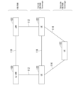
- FIG. 1 is a schematic diagram of a communication system according to an embodiment of the present invention.
- FIG. 13 is a diagram showing an example of a protocol configuration in a discovery procedure according to the embodiment;
- FIG. 2 is a block diagram showing the configuration of a terminal device according to the embodiment.
- FIG. 2 is a block diagram showing the configuration of a base station device according to the embodiment.
- FIG. 1 is a diagram showing an example of a protocol configuration in NR according to this embodiment.
- a diagram of an example of a user plane protocol configuration of an L2 U2N relay in this embodiment. 4 is an example of processing according to the present embodiment.
- each node and entity and the processing in each node and entity when the radio access technology is NR are described, but this embodiment may be applied to other radio access technologies.
- the names of each node and entity in this embodiment may be different names.
- FIG. 1 is a schematic diagram of a communication system according to this embodiment. Note that the functions of each node, radio access technology, core network, interface, etc. described using FIG. 1 are only some of the functions closely related to this embodiment, and the system may have other functions.
- E-UTRA may be a radio access technology.
- E-UTRA may also be an air interface between UE 122 and ng-eNB 100.
- the air interface 112 between UE 122 and ng-eNB 100 may be referred to as a Uu interface.
- the ng-eNB (ng E-UTRAN Node B) 100 may be an E-UTRAN base station device.
- the ng-eNB 100 may have the E-UTRA protocol described below.
- the E-UTRA protocol may be composed of the E-UTRA User Plane (UP) protocol described below and the E-UTRA Control Plane (CP) protocol described below.
- the ng-eNB 100 may terminate the E-UTRA user plane protocol and the E-UTRA control plane protocol for UE 122.
- the radio access network composed of eNBs may be referred to as E-UTRAN.
- NR may be a radio access technology.
- NR may also be an air interface between UE 122 and gNB 102.
- the air interface 112 between UE 122 and gNB 102 may be referred to as a Uu interface.
- gNB (g Node B) 102 may be an NR base station device.
- gNB 102 may have the NR protocol described below.
- the NR protocol may be composed of the NR User Plane (UP) protocol described below and the NR Control Plane (CP) protocol described below.
- gNB 102 may terminate the NR user plane protocol and the NR control plane protocol for UE 122.
- UP NR User Plane
- CP NR Control Plane
- the interface 110 between the ng-eNB 100 and the gNB 102 may be called an Xn interface.
- the ng-eNB and the gNB may be connected to the 5GC via an interface called an NG interface (not shown).
- the 5GC may be a core network.
- One or more base station devices may be connected to the 5GC via an NG interface.
- the state in which a connection to a base station device can be made only via the Uu interface may be called Inside NG-RAN Coverage or In-Coverage (IC). Furthermore, the state in which a connection to a base station device cannot be made only via the Uu interface may be called Outside NG-RAN Coverage or Out-of-Coverage (OoC).
- the air interface 114 between UE122 and UE122 may be called a PC5 interface. Communication between UE122 that is performed via the PC5 interface may be called sidelink (SL) communication. Furthermore, a terminal device capable of sidelink communication may be called a terminal device capable of sidelink communication.
- the ng-eNB100 and/or the gNB102 are also referred to simply as base station devices, and the UE122 is also referred to simply as terminal devices or UEs.
- the PC5 interface is also referred to simply as PC5, and the Uu interface is also referred to simply as Uu.
- Sidelink is a technology that allows direct communication between terminal devices via PC5, and sidelink transmission and reception on PC5 is performed inside and outside NG-RAN coverage.
- NR SL communication has three transmission modes, and SL communication is performed in one of the transmission modes with a pair of a source Layer-2 identifier (Source Layer-2 (L2) ID) and a destination Layer-2 identifier (Destination Layer-2 (L2) ID).
- the source Layer 2 identifier and destination Layer 2 identifier may also be referred to as the source L2 ID and destination L2 ID, respectively.
- the three transmission modes are "unicast transmission", “groupcast transmission”, and “broadcast transmission”.
- the transmission modes may also be referred to as cast types, etc.
- Unicast transmission is characterized by (1) support for one PC5-RRC connection between a paired UE, (2) transmission and reception of control information and user traffic between UEs on the sidelink, (3) support for sidelink HARQ feedback, (4) transmit power control on the sidelink, (5) support for RLC AM, and (6) radio link failure detection for the PC5-RRC connection.
- Groupcast transmission is also characterized by (1) sending and receiving user traffic between UEs belonging to a sidelink group, and (2) supporting sidelink HARQ feedback.
- Broadcast transmissions can also be characterized as (1) sending and receiving user traffic between UEs on the sidelink.
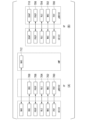
- FIGS. 2 and 3 are diagrams showing an example of a protocol architecture for NR sidelink communication according to this embodiment. Note that the functions of each protocol described using FIG. 2 and/or FIG. 3 are some of the functions closely related to this embodiment, and may have other functions. Note that in this embodiment, a sidelink (SL) may be a link between terminal devices.
- SL sidelink
- FIG. 2(A) is a diagram of the protocol stack of the control plane (CP) for SCCH using RRC configured on the PC5 interface.
- the control plane protocol stack for SCCH using RRC may be composed of PHY (Physical layer) 200, which is the wireless physical layer, MAC (Medium Access Control) 202, which is the medium access control layer, RLC (Radio Link Control) 204, which is the radio link control layer, PDCP (Packet Data Convergence Protocol) 206, which is the packet data convergence protocol layer, and RRC (Radio Resource Control) 208, which is the radio resource control layer.
- Figure 2(B) is a diagram of the protocol stack of the control plane for SCCH using PC5-S configured on the PC5 interface.
- the control plane protocol stack for SCCH using PC5-S may be composed of PHY (Physical layer) 200, which is the wireless physical layer, MAC (Medium Access Control) 202, which is the medium access control layer, RLC (Radio Link Control) 204, which is the radio link control layer, PDCP (Packet Data Convergence Protocol) 206, which is the packet data convergence protocol layer, and PC5-S (PC5 Signalling) 210, which is the PC5 signaling layer.
- PHY Physical layer
- MAC Medium Access Control
- RLC Radio Link Control
- PDCP Packet Data Convergence Protocol
- PC5-S PC5 Signalling
- Figure 3(A) is a diagram of the control plane protocol stack for SBCCH configured on the PC5 interface.
- the control plane protocol stack for SBCCH may be composed of PHY (Physical layer) 200, which is the radio physical layer, MAC (Medium Access Control) 202, which is the medium access control layer, RLC (Radio Link Control) 204, which is the radio link control layer, and RRC (Radio Resource Control) 208, which is the radio resource control layer.
- Figure 3(B) is a diagram of the user plane (User Plane: UP) protocol stack for STCH configured on the PC5 interface.
- PHY Physical layer
- MAC Medium Access Control
- RLC Radio Link Control
- RRC Radio Resource Control
- the control plane protocol stack for the STCH may be composed of PHY (Physical layer) 200, which is the radio physical layer, MAC (Medium Access Control) 202, which is the medium access control layer, RLC (Radio Link Control) 204, which is the radio link control layer, PDCP (Packet Data Convergence Protocol) 206, which is the packet data convergence protocol layer, and SDAP (Service Data Adaptation Protocol) 310, which is the service data adaptation protocol layer.
- PHY Physical layer
- MAC Medium Access Control
- RLC Radio Link Control
- PDCP Packet Data Convergence Protocol
- SDAP Service Data Adaptation Protocol
- the AS (Access Stratum) layer may be a layer including some or all of PHY200, MAC202, RLC204, PDCP206, SDAP310, and RRC208. Also, PC5-S210 and Discovery400, which will be described later, may be layers higher than the AS layer.
- PHY PHY layer
- MAC MAC layer
- RLC RLC layer
- PDCP PDCP layer
- SDAP SDAP layer
- RRC RRC layer
- PC5-S PC5-S layer
- PHY PHY layer
- MAC MAC layer
- RLC RLC layer
- PDCP PDCP layer
- SDAP layer SDAP layer
- RRC RRC layer
- PC5-S layer may respectively be the PHY (PHY layer), MAC (MAC layer), RLC (RLC layer), PDCP (PDCP layer), SDAP (SDAP layer), RRC (RRC layer), and PC5-S (PC5-S layer) of the NR sidelink protocol.
- RLC may be expressed as sidelink RLC
- other protocols may be expressed as protocols for sidelink by adding "sidelink", "SL”, or "PC5" to the beginning.
- E-UTRA PHY or LTE PHY when distinguishing between E-UTRA protocols and NR protocols, PHY, MAC, RLC, PDCP, and RRC may be referred to as E-UTRA PHY or LTE PHY, E-UTRA MAC or LTE MAC, E-UTRA RLC or LTE RLC, E-UTRA PDCP or LTE PDCP, and E-UTRA RRC or LTE RRC, respectively.
- PHY, MAC, RLC, PDCP, and RRC may also be described as E-UTRA PHY or LTE PHY, E-UTRA MAC or LTE MAC, E-UTRA RLC or LTE RLC, E-UTRA PDCP or LTE PDCP, and E-UTRA RRC or LTE RRC, respectively.
- PHY, MAC, RLC, PDCP, and RRC are sometimes referred to as PHY for NR, MAC for NR, RLC for NR, RLC for NR, and RRC for NR, respectively.
- PHY, MAC, RLC, PDCP, and RRC are sometimes referred to as NR PHY, NR MAC, NR RLC, NR PDCP, and NR RRC, respectively.
- An entity having some or all of the physical layer functions may be called a PHY entity.
- An entity having some or all of the MAC layer functions may be called a MAC entity.
- An entity having some or all of the RLC layer functions may be called an RLC entity.
- An entity having some or all of the PDCP layer functions may be called a PDCP entity.
- An entity having some or all of the SDAP layer functions may be called an SDAP entity.
- An entity having some or all of the RRC layer functions may be called an RRC entity.
- the PHY entity, MAC entity, RLC entity, PDCP entity, SDAP entity, and RRC entity may be referred to as PHY, MAC, RLC, PDCP, SDAP, and RRC, respectively.
- each entity in the AS layer may be a common entity for E-UTRA, NR, and/or sidelink, or may be an independent entity.
- MAC PDU Protocol Data Unit
- RLC PDU Packet Data Unit
- PDCP PDU Packet Data Unit
- SDAP PDU Serial Data Unit
- RLC SDU Service Data Unit
- RLC SDU Remote Location Control
- PDCP SDU Packet Data Unit
- SDAP SDU Segmented RLC SDU
- the base station device and the terminal device exchange (send and receive) signals in the higher layer on the Uu interface.
- the higher layer may be referred to as the upper layer, and the terms may be interchangeable.
- the base station device and the terminal device may send and receive RRC messages (also referred to as RRC signaling) in the Radio Resource Control (RRC) layer.
- RRC Radio Resource Control
- the base station device and the terminal device may also send and receive MAC Control Elements (MAC CE) in the Medium Access Control (MAC) layer.
- the RRC layer of the terminal device acquires system information reported from the base station device.
- the RRC message, system information, and/or MAC control elements are also referred to as higher layer signals (higher layer signaling) or higher layer parameters (higher layer parameters).
- a higher layer means a higher layer as seen from the PHY layer, and may mean one or more of the MAC layer, RRC layer, RLC layer, PDCP layer, NAS (Non Access Stratum) layer, etc.
- a higher layer may mean one or more of the RRC layer, RLC layer, PDCP layer, NAS layer, etc.
- Terminal devices also exchange (transmit and receive) signals at the higher layer on the PC5 interface.
- Terminal devices may transmit and receive RRC messages (also referred to as RRC signaling) at the Radio Resource Control (RRC) layer.
- Terminal devices may also transmit and receive MAC Control Elements (MAC CE) at the Medium Access Control (MAC) layer.
- RRC messages and/or MAC control elements are also referred to as higher layer signals (higher layer signaling) or higher layer parameters (higher layer parameters).
- Each of the parameters included in the higher layer signals received by a terminal device may be referred to as a higher layer parameter.
- a higher layer means a higher layer from the perspective of the PHY layer, and may mean one or more of the MAC layer, RRC layer, RLC layer, PDCP layer, PC5-S layer, Discovery layer, etc.
- a higher layer may mean one or more of the RRC layer, RLC layer, PDCP layer, PC5-S layer, Discovery layer, etc.
- the meaning of "A is given (provided) by the upper layer” or “A is given (provided) by the upper layer” may mean that the upper layer (mainly the RRC layer or the MAC layer, etc.) of the terminal device receives A from a base station device or another terminal device, and the received A is given (provided) from the upper layer of the terminal device to the physical layer of the terminal device.
- “upper layer parameters are provided” may mean that an upper layer signal is received from a base station device or another terminal device, and the upper layer parameters included in the received upper layer signal are provided from the upper layer of the terminal device to the physical layer of the terminal device.
- Setting upper layer parameters in a terminal device may mean that the upper layer parameters are given (provided) to the terminal device.
- setting upper layer parameters in a terminal device may mean that the terminal device receives an upper layer signal from a base station device or another terminal device, and the received upper layer parameters are set in the upper layer.
- setting upper layer parameters in a terminal device may include setting default parameters that are given in advance to the upper layer of the terminal device.
- "submitting a message to a lower layer” from the RRC entity may mean submitting a message to the PDCP layer.
- "submitting a message to a lower layer” from the RRC layer may mean submitting to the PDCP entity corresponding to each SRB, since RRC messages are transmitted using SRBs (SRB0, SRB1, SRB2, SRB3, etc.).
- the lower layer may mean one or more of the PHY layer, MAC layer, RLC layer, PDCP layer, etc.
- the PHY of a terminal device may have the function of transmitting and receiving data transmitted via a sidelink (SL) physical channel with the PHY of another terminal device.
- the PHY may be connected to a higher MAC via a transport channel.
- the PHY may pass data to the MAC via the transport channel.
- the PHY may also be provided with data from the MAC via the transport channel.
- a Radio Network Temporary Identifier (RNTI) may be used to identify various control information.
- RNTI Radio Network Temporary Identifier
- the physical channels used for wireless communication between a terminal device and another terminal device may include the following physical channels:
- PSBCH Physical Sidelink Broadcast CHannel
- PSCCH Physical Sidelink Control CHannel
- PSSCH Physical Sidelink Shared CHannel
- PSFCH Physical Sidelink Feedback CHannel
- PSBCH may be used to notify the terminal device of system information required.
- the PSCCH may be used to indicate resources and other transmission parameters related to the PSSCH.
- the PSSCH may be used to transmit data and control information regarding HARQ/CSI feedback to other terminal devices.
- the PSFCH may be used to carry HARQ feedback to other terminal devices.
- the MAC may be called a MAC sublayer.
- the MAC may have the function of mapping various logical channels to corresponding transport channels.
- the logical channels may be identified by a logical channel identifier (Logical Channel Identity, or Logical Channel ID).
- Logical Channel ID Logical Channel Identity
- the MAC may be connected to the higher-level RLC via a logical channel.
- the logical channels may be divided into a control channel that transmits control information and a traffic channel that transmits user information.
- the MAC may have the function of multiplexing MAC SDUs belonging to one or more different logical channels and providing them to the PHY.
- the MAC may also have the function of demultiplexing MAC PDUs provided by the PHY and providing them to the higher layer via the logical channel to which each MAC SDU belongs.
- the MAC may also have the function of performing error correction through HARQ (Hybrid Automatic Repeat reQuest).
- the MAC may also have the function of reporting scheduling information.
- the MAC may have the function of performing priority processing between terminal devices using dynamic scheduling.
- the MAC may also have the function of performing priority processing between logical channels within a single terminal device.
- the MAC may have the function of performing priority processing of overlapping resources within a single terminal device.
- the E-UTRA MAC may have the function of identifying Multimedia Broadcast Multicast Services (MBMS).
- MBMS Multimedia Broadcast Multicast Services
- the NR MAC may also have the function of identifying Multicast/Broadcast Services (MBS).
- the MAC may have the function of selecting a transport format.
- the MAC may have functions such as discontinuous reception (DRX) and/or discontinuous transmission (DTX), a function to execute random access (RA) procedures, a power headroom report (PHR) function to notify information on the transmit power available, and a buffer status report (BSR) function to notify information on the amount of data in the transmit buffer.
- DRX discontinuous reception
- DTX discontinuous transmission
- PHR power headroom report
- BSR buffer status report
- the NR MAC may have a bandwidth adaptation (BA) function.
- BA bandwidth adaptation
- the MAC PDU format used in the E-UTRA MAC may differ from the MAC PDU format used in the NR MAC.
- the MAC PDU may also include a MAC control element (MAC CE), which is an element for performing control in the MAC.
- MAC CE MAC control element
- the MAC sublayer may also provide additional services and functions on the PC5 interface, such as radio resource selection for selecting radio resources for sidelink transmission, filtering of packets received in sidelink communication, priority processing between uplink and sidelink, and reporting of sidelink channel state information (Sidelink CSI).
- radio resource selection for selecting radio resources for sidelink transmission
- filtering of packets received in sidelink communication filtering of packets received in sidelink communication
- priority processing between uplink and sidelink priority processing between uplink and sidelink
- reporting of sidelink channel state information Sidelink CSI
- This article explains the sidelink (SL) logical channels used in E-UTRA and/or NR, and the mapping between the sidelink logical channels and transport channels.
- the SBCCH (Sidelink Broadcast Control Channel) may be a logical channel for sidelink to broadcast sidelink system information from one terminal device to one or more terminal devices.
- the SBCCH may also be mapped to the SL-BCH, which is a sidelink transport channel.
- the SCCH may be a sidelink logical channel for transmitting control information such as PC5-RRC messages and PC5-S messages from one terminal device to one or more terminal devices.
- the SCCH may also be mapped to the SL-SCH, which is a sidelink transport channel.
- STCH (Sidelink Traffic Control Channel) may be a sidelink logical channel for transmitting user information from one terminal device to one or more terminal devices.
- STCH may also be mapped to SL-SCH, which is a sidelink transport channel.
- RLC may be called an RLC sublayer.
- E-UTRA RLC may have the function of segmenting and/or concatenating data provided from the upper layer PDCP and providing it to the lower layer.
- E-UTRA RLC may have the function of reassembling and reordering data provided from the lower layer and providing it to the upper layer.
- NR RLC may have the function of adding a sequence number independent of the sequence number added by PDCP to data provided from the upper layer PDCP.
- NR RLC may also have the function of segmenting data provided from PDCP and providing it to the lower layer.
- NR RLC may also have the function of reassembling data provided from the lower layer and providing it to the upper layer.
- RLC may also have the function of retransmitting data and/or requesting retransmission (Automatic Repeat reQuest: ARQ). RLC may also have the function of performing error correction using ARQ.
- the control information sent from the receiving side of RLC to the transmitting side to perform ARQ, indicating the data that needs to be retransmitted, may be called a status report.
- the instruction to send a status report sent from the transmitting side of RLC to the receiving side may be called a poll.
- RLC may also have the function of detecting data duplication.
- RLC may also have the function of discarding data. RLC may have three modes: Transparent Mode (TM), Unacknowledged Mode (UM), and Acknowledged Mode (AM).
- TM data received from the upper layer is not divided, and an RLC header does not need to be added.
- the TM RLC entity is a uni-directional entity and may be configured as a transmitting TM RLC entity or a receiving TM RLC entity.
- UM the data received from the upper layer may be divided and/or combined, an RLC header may be added, etc., but data retransmission control is not required.
- the UM RLC entity may be a unidirectional entity or a bi-directional entity. If the UM RLC entity is a unidirectional entity, it may be configured as a transmitting UM RLC entity or a receiving UM RLC entity.
- the UM RRC entity may be configured as a UM RLC entity consisting of a transmitting side and a receiving side.
- the data received from the upper layer may be divided and/or combined, an RLC header may be added, data retransmission control is required, etc.
- the AM RLC entity is a bi-directional entity and may be configured as an AM RLC consisting of a transmitting side and a receiving side.
- data provided to the lower layer in TM and/or data provided from the lower layer may be called TMD PDU.
- data provided to a lower layer in UM and/or data provided by a lower layer may be referred to as a UMD PDU.
- RLC PDU data provided to a lower layer in AM and/or data provided by a lower layer may be referred to as an AMD PDU.
- the RLC PDU format used in E-UTRA RLC may differ from the RLC PDU format used in NR RLC.
- RLC PDUs may include RLC PDUs for data and RLC PDUs for control.
- the RLC PDUs for data may be referred to as RLC DATA PDU (RLC Data PDU, RLC Data PDU).
- RLC PDUs for control may be referred to as RLC CONTROL PDU (RLC Control PDU, RLC Control PDU, RLC Control PDU).
- the RLC PDUs for control used to send status reports may be referred to as status PDU (STATUS PDU).
- TM may be used for SBCCH
- UM is used in groupcast and broadcast transmissions
- UM and AM can be used in unicast transmissions.
- UM in groupcast and broadcast transmissions supports only unidirectional transmission.
- PDCP may be called a PDCP sublayer.
- PDCP may have a function for maintaining sequence numbers.
- PDCP may also have a header compression/decompression function for efficiently transmitting user data such as IP packets and Ethernet frames over wireless sections.
- the protocol used for IP packet header compression/decompression may be called the ROHC (Robust Header Compression) protocol.
- the protocol used for Ethernet frame header compression/decompression may be called the EHC (Ethernet (registered trademark) Header Compression) protocol.
- PDCP may also have a data encryption/decryption function.
- PDCP may also have data integrity protection/verification functions.
- PDCP may also have a re-ordering function.
- PDCP may also have a PDCP SDU retransmission function.
- PDCP may also have a data discard function using a discard timer.
- PDCP may also have a duplication function.
- PDCP may also have the function of discarding duplicated data received.
- the PDCP entity is a bidirectional entity and may consist of a transmitting PDCP entity and a receiving PDCP entity.
- the PDCP PDU format used in E-UTRA PDCP may differ from the PDCP PDU format used in NR PDCP.
- PDCP PDUs may include data PDCP PDUs and control PDCP PDUs.
- the data PDCP PDU may be called PDCP DATA PDU (PDCP Data PDU, PDCP Data PDU).
- the control PDCP PDU may be called PDCP CONTROL PDU (PDCP Control PDU, PDCP Control PDU, PDCP Control PDU).
- SDAP is a service data adaptation protocol layer.
- SDAP may have a function of mapping the sidelink QoS flow sent from a terminal device to another terminal device with a sidelink data radio bearer (DRB).
- SDAP may also have a function of storing mapping rule information.
- SDAP may also have a function of marking the QoS flow identifier (QoS Flow ID: QFI).
- QFI QoS Flow ID
- SDAP PDUs may include data SDAP PDUs and control SDAP PDUs.
- Data SDAP PDUs may be called SDAP DATA PDUs (SDAP Data PDUs, SDAP Data PDUs).
- SDAP CONTROL PDUs may be called SDAP CONTROL PDUs (SDAP Control PDUs, SDAP Control PDUs, SDAP Control PDUs).
- SDAP entity of the terminal device may exist for each destination for unicast transmission, groupcast transmission, or broadcast transmission associated with the destination. Also, reflective QoS is not supported on the PC5 interface.
- RRC may support services and functions such as forwarding PC5-RRC messages between peer UEs on the PC5 interface, maintaining and releasing PC5-RRC connections between two UEs, and detecting sidelink radio link failures for PC5-RRC connections.
- a PC5-RRC connection is a logical connection between two UEs corresponding to a pair of source L2ID and destination L2ID, and is considered to be established after the corresponding PC5 unicast link is established. There is also a one-to-one correspondence between the PC5-RRC connection and the PC5 unicast link.
- a UE may have multiple PC5-RRC connections to one or multiple UEs for different pairs of source L2ID and destination L2ID.
- PC5-RRC procedures and messages may be used by the UE to forward UE capabilities and sidelink configuration to the peer UE. Both peer UEs may also exchange their UE capabilities and sidelink configurations with each other using separate bidirectional procedures. The UE releases the PC5-RRC connection if it is not interested in sidelink transmissions, if a sidelink radio link failure is detected for the PC5-RRC connection, and if the Layer 2 link release procedure is completed.
- a UE performing sidelink transmission may transmit a PSCCH in association with a PSSCH.
- sidelink transmission may be transmitting a signal and/or data (message) via a physical channel for sidelink (PSBCH, PSSCH, PSCCH, etc.)
- sidelink reception may be receiving a signal and/or data (message) via a physical channel for sidelink.
- communication using sidelink transmission and sidelink reception may be referred to as sidelink communication.
- the UE may recognize the data (message) based on the signal.
- Each PSSCH transmission may be associated with a PSCCH (a PSCCH) transmission.
- the PSCCH transmission may carry a first SCI (1st stage of the SCI) associated with the PSSCH transmission, and a second SCI (2nd stage of the SCI) may be carried within the resources of the PSSCH (the PSSCH).
- the PSCCH transmission may include a first SCI
- the PSSCH transmission may include a second SCI.
- the PSCCH transmission and the PSSCH transmission may be referred to as sidelink transmissions, and the SCI may be sidelink control information.
- the first SCI may include information in a format called SCI format 1-A, and may be used for scheduling the PSSCH and the second SCI on the PSSCH.
- SCI format 1-A may include information such as data priority, frequency resources and time resources on which the PSSCH is transmitted, resource reservation period, DMRS placement pattern, second SCI format, beta offset indication value, number of DMRS ports, information indicating modulation and coding scheme, and may include other information.
- the SCI carried on the PSSCH may be a second SCI, which may transport sidelink scheduling information and/or information related to inter-UE coordination.
- the second SCI may include information in a format called SCI format 2-A, SCI format 2-B, SCI format 2-C, etc.
- SCI format 2-A, SCI format 2-B, and SCI format 2-C may include information such as HARQ process related information, information indicating whether data is new, redundancy version, source ID for identifying a source UE, destination ID for identifying a destination UE, and information indicating whether HARQ feedback is possible.
- SCI format 2-A may additionally include information indicating a cast type and information indicating whether channel state information (CSI) is requested.
- SCI format 2-B may additionally include an identifier indicating a zone and request information regarding communication range.
- SCI format 2-C may additionally include information indicating whether to request channel state information, and information indicating whether to provide or request inter-UE coordination information.
- SCI format 2-C may additionally include information such as information indicating a resource combination, information indicating the first resource position, position information of the reference slot, information indicating the type of resource set, and lowest subchannel index.
- SCI format 2-C may additionally include information such as priority, number of subchannels, resource reservation interval, position of the resource selection window, and information indicating the type of resource set. Note that each SCI format may include information other than the above-mentioned information.
- the procedure of the UE receiving the PSSCH will be described.
- the UE detects SCI format 1-A on the PSCCH, it can decode the PSSCH according to the detected SCI format 2-A or SCI format 2-B and the associated PSSCH resource configuration configured by the higher layer. Note that the UE does not need to decode more than one PSCCH for each PSCCH resource candidate. Also, if the UE does not support the modulation and coding scheme indicated in SCI format 1-A, it does not need to decode the corresponding SCI format 2-A and SCI format 2-B, and the PSSCH associated with SCI format 1-A.
- the UE may also measure the PSSCH RSRP from the DMRS resource element for the PSSCH associated with the received SCI format 1-A if PSSCH is set in the parameter indicating whether the DMRS used for L1 RSRP measurement during the sensing operation is the DMRS of the PSCCH or the DMRS of the PSSCH at the higher (RRC) layer, and may measure the PSCCH RSRP from the DMRS resource element for the PSCCH associated with the received SCI format 1-A if PSCCH is set.
- RRC higher
- a terminal device capable of sidelink communication may perform discovery.
- There may be Model A and Model B for discovery.
- Figure 4 shows the protocol stack for the discovery procedure.
- Mode A may use a single discovery protocol message
- Model B may use two discovery protocol messages.
- the single discovery protocol message in Model A may be an Announcement message
- the discovery protocol messages in Model B may be a Solicitation message and a Response message.
- the Announcement message, Solicitation message, and Response message may be collectively referred to as discovery messages, and messages with other names used in the discovery procedure may be referred to as discovery messages.
- a UE that transmits an announcement message may be referred to as an Announcing UE, and a UE that monitors the announcement message may be referred to as a Monitoring UE.
- the announcement message may include information such as the type of discovery message, ProSe Application Code or ProSe Restricted Code, and security protection element, and may additionally include metadata information.
- the announcement message is transmitted using a Destination Layer-2 ID (L2ID) and a Source Layer-2 ID (L2ID), and the monitoring UE determines the destination L2ID to receive the announcement message.
- L2ID Destination Layer-2 ID
- L2ID Source Layer-2 ID
- the monitoring UE determines the destination L2ID to receive the announcement message.
- the destination L2ID may be the Layer-2 identifier of the destination UE
- the source L2ID may be the Layer-2 identifier of the source UE.
- the destination UE may simply be referred to as the destination.
- a UE that sends a solicitation message may be referred to as a discoverer UE, and a UE that receives the solicitation message and/or sends a response message to the discoverer UE may be referred to as a discoveree UE.
- the solicitation message may include information such as a discovery message type, a ProSe Query Code, and a security protection element.
- the solicitation message is sent using a destination L2ID and a source L2ID, and the discoveree UE determines a destination L2ID to receive the solicitation message.
- the discoveree UE responding to the solicitation message also sends a response message.
- the response message may include information such as a discovery message type, a ProSe Response Code, and a security protection element, and may also include additional metadata information.
- the response message is sent using a source L2ID, and the destination L2ID is set to the source L2ID of the received solicitation message.
- ProSe Direct Discovery may include types other than ProSe Direct Discovery, which discovers other UEs in order to communicate directly with them, such as Group member Discovery, which discovers one or more UEs in order to communicate within a group using sidelink, and 5G ProSe UE-to-Network Relay Discovery, which discovers candidate relay UEs in order to connect to the network via a relay UE.
- Group member Discovery which discovers one or more UEs in order to communicate within a group using sidelink
- 5G ProSe UE-to-Network Relay Discovery which discovers candidate relay UEs in order to connect to the network via a relay UE.
- the above-mentioned discovery is an example of discovery provided by an application called ProSe, but in addition to the above-mentioned types, there may be different types of discovery depending on the application or service that performs sidelink communication.
- the information included in the discovery protocol message may differ depending on the type of discovery, and additional messages may be sent to transmit additional information.
- FIG. 4 is a diagram of an example of a protocol configuration including a discovery protocol according to this embodiment.
- the protocol stack of the discovery plane including the discovery protocol may be composed of PHY (Physical layer) 200, which is a wireless physical layer, MAC (Medium Access Control) 202, which is a medium access control layer, RLC (Radio Link Control) 204, which is a radio link control layer, PDCP (Packet Data Convergence Protocol) 206, which is a packet data convergence protocol layer, and Discovery 400, which is a discovery protocol layer.
- Discovery 400 may be a protocol used to process procedures related to discovery.
- the interface between UEs performing discovery may be referred to as PC5-D.
- Multiple resource pools may be configured for transmitting messages (discovery messages) used in discovery procedures, or one or more resource pools may be configured exclusively for discovery. If a resource pool dedicated to discovery is configured, the UE may use the resource pool dedicated to discovery as the resource pool for transmitting discovery messages, and if a resource pool dedicated to discovery is not configured, the UE may use the resource pool for sidelink communications as the resource pool for transmitting discovery messages. Note that multiple resource pools for sidelink communications and multiple resource pools dedicated to discovery may be configured at the same time. Each resource pool may be configured by UE-dedicated signaling, or may be configured in advance.
- a sidelink signaling radio bearer may be configured in each unicast PC5-RRC connection.
- a sidelink SRB used to transmit PC5-S messages before PC5-S security is established may be referred to as SL-SRB0.
- a sidelink SRB used to transmit PC5-S messages for establishing PC5-S security may be referred to as SL-SRB1.
- a sidelink SRB used to transmit protected PC5-S messages after PC5-S security is established may be referred to as SL-SRB2.
- a sidelink SRB used to transmit protected PC5-RRC signaling after PC5-S security is established may be referred to as SL-SRB3.
- a sidelink SRB used to transmit and/or receive discovery messages in NR may be referred to as SL-SRB4.
- PC5-RRC signaling may be RRC signaling between UEs transmitted and received on PC5.
- PC5-RRC signaling may be referred to as PC5-RRC message, etc.
- U2N relay may be a function that provides network connectivity for remote terminal equipment (Remote UE).
- a remote terminal equipment that connects to a network using a U2N relay may be called a U2N Remote UE.
- a terminal equipment that provides network connectivity for a U2N Remote UE may be called a U2N relay terminal equipment (Relay UE), or simply a relay terminal equipment (Relay UE).
- a U2N Relay UE may use a Uu interface to communicate with a base station equipment, or may use a PC5 interface to communicate with a U2N Remote UE.
- U2N relay there may be types of U2N relay, such as a Layer 2 (L2) U2N relay and a Layer 3 (L3) U2N relay.
- a remote terminal device in an L2 U2N relay may be specifically referred to as an L2 U2N Remote UE, and a relay terminal device in an L2 U2N relay may be specifically referred to as an L2 U2N Relay UE.
- SRAP Sidelink Relay Adaptation Protocol
- Figure 8 is a diagram showing an example of a protocol configuration of the control plane (C-plane) of an L2 U2N relay, including an SRAP layer (SRAP800) according to this embodiment.
- Figure 9 is a diagram showing an example of a protocol configuration of the user plane (U-plane) of an L2 U2N relay, including an SRAP layer according to this embodiment.
- the SRAP layer may be associated between a Remote UE and a Relay UE, and may also be associated between a Relay UE and a gNB102.
- the gNB102 shown in Figures 8 and 9 may be an ng-eNB100.
- the Remote UE or Relay UE may be UE122.
- the Relay UE may have the same configuration as UE122.
- the SRAP layer may be called the SRAP sublayer, or simply SRAP.
- the SRAP sublayer may exist above the RLC sublayer for the control plane and user plane of both the PC5 interface and the Uu interface.
- the SRAP sublayer on PC5 may be used for bearer mapping purposes.
- the SRAP sublayer may include one SRAP entity on the Uu interface and a separate collocated SRAP entity on the PC5 interface.
- the SRAP sublayer may include only one SRAP entity on the PC5 interface.
- the SRAP entity associated between the Remote UE and Relay UE via the PC5 interface may be specifically referred to as PC5-SRAP, and the SRAP entity associated between the Relay UE and gNB via Uu may be specifically referred to as Uu-SRAP.
- other entities may also be expressed in the format (interface name)-(entity name) as in the case of SRAP.
- Each SRAP entity may have a transmitter and a receiver.
- the transmitter of the SRAP entity of the L2 U2N Remote UE may be associated with the receiver of the SRAP entity of the L2 U2N Relay UE, and the receiver of the SRAP entity of the L2 U2N Remote UE may be associated with the transmitter of the SRAP entity of the L2 U2N Relay UE.
- the transmitter of the SRAP entity of the L2 U2N Relay UE may be associated with the receiver of the SRAP entity of the gNB102, and the receiver of the SRAP entity of the L2 U2N Relay UE may be associated with the transmitter of the SRAP entity of the gNB102.
- the SRAP entity may also have the functions of forwarding data, determining the UE ID field and bearer ID field of the SRAP header to be added to the data packet, determining the exit link, and determining the exit RLC channel.
- a PC5 Relay RLC channel may be established between the Remote UE and the Relay UE, and a Uu Relay RLC channel may be established between the Relay UE and gNB102.
- the protocol used between the base station device and the terminal device may be used in the communication performed at the Uu interface between the relay terminal device and the base station device, and in the communication performed between the remote terminal device and the base station device via the relay terminal device. Note that in the communication performed between the remote terminal device and the base station device via the relay terminal device, some protocols may not be associated between the remote terminal device and the base station device.
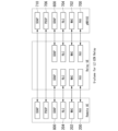
- FIG. 7 is a diagram of an example of the NR protocol configuration according to this embodiment.
- the functions of each protocol described using FIG. 7 are some of the functions closely related to this embodiment, and may have other functions.
- the uplink (UL) may be a link from the terminal device to the base station device.
- the downlink (DL) may be a link from the base station device to the terminal device.
- Figure 7(A) is a diagram of the NR control plane (CP) protocol stack.
- the NR CP protocol may be a protocol between the UE 122 and the gNB 102. That is, the NR CP protocol may be a protocol that terminates at the gNB 102 on the network side.
- the NR control plane protocol stack may be composed of PHY (Physical layer) 700, which is the radio physical layer, MAC (Medium Access Control) 702, which is the medium access control layer, RLC 704, which is the radio link control layer, PDCP (Packet Data Convergence Protocol) 706, which is the packet data convergence protocol layer, and RRC (Radio Resource Control) 708, which is the radio resource control layer.
- PHY Physical layer
- MAC Medium Access Control
- RLC 704 which is the radio link control layer
- PDCP Packet Data Convergence Protocol
- RRC Radio Resource Control
- Figure 7(B) is a diagram of the NR user plane (UP) protocol stack.
- the NR UP protocol may be a protocol between the UE 122 and the gNB 102. That is, the NR UP protocol may be a protocol that terminates at the gNB 102 on the network side.
- the NR user plane protocol stack may be composed of a radio physical layer, PHY 700, a medium access control layer, MAC 702, a radio link control layer, RLC 704, a packet data convergence protocol layer, PDCP 706, and a service data adaptation protocol layer, SDAP (Service Data Adaptation Protocol) 710.
- the AS (Access Stratum) layer may be a layer that terminates between the UE 122 and the gNB 102.
- the AS layer may be a layer that includes some or all of the PHY 700, MAC 702, RLC 704, PDCP 706, and RRC 708.
- the gNB 102 may be an ng-eNB 100.
- the E-UTRA protocol may also be used. In the E-UTRA protocol, the SDAP 710 may not exist, and the E-UTRA protocol may have some functions that differ from those of the NR protocol.
- the PHY of the terminal device may have a function of receiving data transmitted from the PHY of the base station device via a downlink (DL) physical channel.
- the PHY of the terminal device may have a function of transmitting data to the PHY of the base station device via an uplink (UL) physical channel.
- the PHY may be connected to an upper MAC via a transport channel.
- the PHY may pass data to the MAC via the transport channel.
- the PHY may also be provided with data from the MAC via the transport channel.
- a Radio Network Temporary Identifier RNTI
- RNTI Radio Network Temporary Identifier
- the physical channels used for wireless communication between a terminal device and a base station device may include the following physical channels:
- PBCH Physical Broadcast CHannel
- PDCCH Physical Downlink Control CHannel
- PDSCH Physical Downlink Shared CHannel
- PUCCH Physical Uplink Control CHannel
- PUSCH Physical Uplink Shared CHannel
- PRACH Physical Random Access CHannel
- the PBCH may be used to notify the terminal device of system information required.
- the PBCH may be used to report the time index (SSB-Index) within the period of a synchronization signal block (SSB).
- SSB-Index time index within the period of a synchronization signal block
- the PDCCH may be used to transmit (or carry) downlink control information (DCI) in downlink wireless communication (wireless communication from a base station device to a terminal device).
- DCI downlink control information
- one or more DCIs (which may also be referred to as DCI formats) may be defined for the transmission of the downlink control information. That is, a field for the downlink control information may be defined as a DCI and mapped to information bits.
- the PDCCH may be transmitted in PDCCH candidates.
- the terminal device may monitor a set of PDCCH candidates in a serving cell. Monitoring a set of PDCCH candidates may mean attempting to decode the PDCCH according to a certain DCI format.
- the terminal device may monitor the PDCCH candidates in configured monitoring occasions in one or more configured control resource sets (CORESET: Control Resource Set) configured by search space configuration.
- CORESET Control Resource Set
- the DCI format may be used for scheduling the PUSCH in the serving cell.
- the PUSCH may be used to transmit user data and RRC messages, which are described below.
- PDCCH repetition may be operated by using two search space sets that are explicitly linked by a configuration provided by a higher layer (RRC layer), and the two linked search space sets may be associated with a corresponding CORESET.
- RRC layer a higher layer
- the two linked search space sets may be configured in the terminal device with the same number of PDCCH candidates.
- the two PDCCH candidates present in the two linked search space sets may be linked by the same candidate index.
- inter-slot repetition may be allowed, and each repetition may have the same number of Control Channel Elements (CCEs) and coded bits, and the same DCI payload.
- CCEs Control Channel Elements
- the PUCCH may be used to transmit uplink control information (UCI) in uplink wireless communication (wireless communication from a terminal device to a base station device).
- the uplink control information may include channel state information (CSI: Channel State Information) used to indicate the state of the downlink channel.
- CSI Channel State Information
- the uplink control information may also include a scheduling request (SR: Scheduling Request) used to request UL-SCH (UL-SCH: Uplink Shared CHannel) resources.
- SR Scheduling Request
- UL-SCH Uplink Shared CHannel
- the uplink control information may also include a HARQ-ACK (Hybrid Automatic Repeat reQuest ACKnowledgement).
- the PDSCH may be used to transmit downlink data (DL-SCH: Downlink Shared CHannel) from the MAC layer.
- DL-SCH Downlink Shared CHannel
- the PDSCH may also be used to transmit system information (SI: System Information) and random access response (RAR: Random Access Response).
- SI System Information
- RAR Random Access Response
- PUSCH may be used to transmit uplink data from the MAC layer (UL-SCH: Uplink Shared CHannel) or HARQ-ACK and/or CSI together with uplink data. PUSCH may also be used to transmit only CSI, or only HARQ-ACK and CSI. That is, PUSCH may be used to transmit only UCI. PDSCH or PUSCH may also be used to transmit RRC messages and MAC CE, which will be described later.
- the RRC message transmitted from the base station device may be common signaling for multiple terminal devices in the cell.
- the RRC message transmitted from the base station device may also be dedicated signaling for a certain terminal device. That is, terminal device-specific (UE specific) information may be transmitted using dedicated signaling for a certain terminal device.
- PUSCH may also be used to transmit UE capabilities in the uplink.
- the PRACH may be used to transmit a random access preamble.
- the PRACH may also be used for initial connection establishment procedures, handover procedures, connection re-establishment procedures, synchronization (timing adjustment) for uplink transmissions, and to indicate requests for UL-SCH resources.
- This article explains the logical channels for the uplink (UL) and/or downlink (DL) used in E-UTRA and/or NR.
- the BCCH (Broadcast Control Channel) may be a downlink logical channel for broadcasting control information such as system information (SI).
- SI system information
- PCCH Packet Control Channel
- PCCH Packet Control Channel
- the Common Control Channel may be a logical channel for transmitting control information between a terminal device and a base station device.
- the CCCH may be used when the terminal device does not have an RRC connection.
- the CCCH may also be used between a base station device and multiple terminal devices.
- DCCH (Dedicated Control Channel) may be a logical channel for transmitting dedicated control information in a point-to-point bidirectional manner between a terminal device and a base station device.
- the dedicated control information may be control information dedicated to each terminal device.
- DCCH may be used when the terminal device has an RRC connection.
- DTCH (Dedicated Traffic Channel) may be a logical channel for transmitting user data point-to-point between a terminal device and a base station device.
- DTCH may be a logical channel for transmitting dedicated user data.
- Dedicated user data may be user data dedicated to each terminal device.
- DTCH may exist in both the uplink and downlink.
- mapping of logical channels and transport channels for the uplink in E-UTRA and/or NR Describes the mapping of logical channels and transport channels for the uplink in E-UTRA and/or NR.
- the CCCH may be mapped to the uplink transport channel, UL-SCH (Uplink Shared Channel).
- UL-SCH Uplink Shared Channel
- the DCCH may be mapped to the uplink transport channel, UL-SCH (Uplink Shared Channel).
- UL-SCH Uplink Shared Channel
- the DTCH may be mapped to the uplink transport channel, UL-SCH (Uplink Shared Channel).
- UL-SCH Uplink Shared Channel
- mapping of logical channels and transport channels for the downlink in E-UTRA and/or NR Describes the mapping of logical channels and transport channels for the downlink in E-UTRA and/or NR.
- the BCCH may be mapped to the downlink transport channels BCH (Broadcast Channel) and/or DL-SCH (Downlink Shared Channel).
- BCH Broadcast Channel
- DL-SCH Downlink Shared Channel
- the PCCH may be mapped to the PCH (Paging Channel), which is a downlink transport channel.
- PCH Packet Control Channel
- the CCCH may be mapped to the downlink transport channel, DL-SCH (Downlink Shared Channel).
- DL-SCH Downlink Shared Channel
- the DCCH may be mapped to the downlink transport channel, DL-SCH (Downlink Shared Channel).
- DL-SCH Downlink Shared Channel
- DTCH may be mapped to the downlink transport channel, DL-SCH (Downlink Shared Channel).
- DL-SCH Downlink Shared Channel
- SDAP is a service data adaptation protocol layer.
- SDAP may have a function to map the downlink QoS flow sent from 5GC to the terminal device via the base station device with the data radio bearer (DRB), and/or map the uplink QoS flow sent from the terminal device to 5GC via the base station device with the DRB.
- SDAP may also have a function to store mapping rule information.
- SDAP may also have a function to mark the QoS flow identifier (QoS Flow ID: QFI).
- QFI QoS Flow ID
- RRC may have a broadcast function.
- RRC may have a paging function from 5GC.
- RRC may have a paging function from gNB102 or ng-eNB100.
- RRC may also have an RRC connection management function.
- RRC may have a radio bearer control function.
- RRC may have a cell group control function.
- RRC may also have a mobility control function.
- RRC may also have terminal device measurement reporting and terminal device measurement reporting control functions.
- RRC may also have a QoS management function.
- RRC may also have a radio link failure detection and recovery function.
- RRC may use RRC messages to perform broadcasting, paging, RRC connection management, radio bearer control, cell group control, mobility control, terminal device measurement reporting and terminal device measurement reporting control, QoS management, radio link failure detection and recovery, etc. Note that the RRC messages and parameters used in E-UTRA RRC may differ from the RRC messages and parameters used in NR RRC.
- the RRC messages may be sent using the logical channel BCCH, the logical channel PCCH, the logical channel CCCH, or the logical channel DCCH.
- RRC messages sent using the DCCH are called Dedicated RRC signaling, or RRC signaling.
- RRC messages sent using the BCCH may include, for example, a Master Information Block (MIB), various types of System Information Blocks (SIBs), and other RRC messages.
- RRC messages sent using the PCCH may include, for example, paging messages, and other RRC messages.
- RRC messages sent in the uplink (UL) direction using the CCCH may include, for example, an RRC setup request message (RRC Setup Request), an RRC resume request message (RRC Resume Request), an RRC reestablishment request message (RRC Reestablishment Request), an RRC system information request message (RRC System Info Request), etc. They may also include, for example, an RRC connection request message (RRC Connection Request), an RRC connection resume request message (RRC Connection Resume Request), an RRC connection reestablishment request message (RRC Connection Reestablishment Request), etc. They may also include other RRC messages.
- RRC messages sent in the downlink (DL) direction using the CCCH may include, for example, an RRC connection reject message (RRC Connection Reject), an RRC connection setup message (RRC Connection Setup), an RRC connection reestablishment message (RRC Connection Reestablishment Reject), an RRC connection reestablishment reject message (RRC Connection Reestablishment Reject), etc. They may also include, for example, an RRC reject message (RRC Reject), an RRC setup message (RRC Setup), etc. They may also include other RRC messages.
- RRC signalling sent in the uplink (UL) direction using the DCCH may include, for example, a measurement report message (Measurement Report), an RRC connection reconfiguration complete message (RRC Connection Reconfiguration Complete), an RRC connection setup complete message (RRC Connection Setup Complete), an RRC connection reestablishment complete message (RRC Connection Reestablishment Complete), a security mode complete message (Security Mode Complete), and a UE capability information message (UE Capability Information).
- Measurement Report Measurement Report
- RRC Connection Reconfiguration Complete RRC connection reconfiguration Complete
- RRC Connection Setup Complete RRC connection setup complete message
- RRC Connection reestablishment complete RRC Connection Reestablishment Complete
- a security mode complete message Security Mode Complete
- UE Capability Information UE Capability Information
- It may also include, for example, a measurement report message (Measurement Report), an RRC reconfiguration complete message (RRC Reconfiguration Complete), an RRC setup complete message (RRC Setup Complete), an RRC reestablishment complete message (RRC Resumé Complete), a security mode complete message (Security Mode Complete), a UE capability information message (UE Capability Information), etc. It may also include other RRC signaling.
- the RRC signaling sent in the downlink (DL) direction using the DCCH may include, for example, an RRC connection reconfiguration message (RRC Connection Reconfiguration), an RRC connection release message (RRC Connection Release), a security mode command message (Security Mode Command), a UE capability enquiry message (UE Capability Enquiry), etc. It may also include, for example, an RRC reconfiguration message (RRC Reconfiguration), an RRC resume message (RRC Resume), an RRC release message (RRC Release), an RRC reestablishment message (RRC Reestablishment), a security mode command message (Security Mode Command), a UE capability enquiry message (UE Capability Enquiry), etc. It may also include other RRC signaling.
- radio bearers When a terminal device communicates with a base station device, a wireless connection may be established by establishing a radio bearer (RB: Radio Bearer) between the terminal device and the base station device.
- the radio bearer used for CP may be called a signaling radio bearer (SRB: Signaling Radio Bearer).
- the radio bearer used for UP may be called a data radio bearer (DRB: Data Radio Bearer).
- Each radio bearer may be assigned a radio bearer identifier (Identity: ID).
- the radio bearer identifier for an SRB may be called an SRB identifier (SRB Identity, or SRB ID).
- the radio bearer identifier for a DRB may be called a DRB identifier (DRB Identity, or DRB ID).
- SRB0 to SRB2 may be defined for the SRB of E-UTRA, and other SRBs may also be defined.
- NR SRBs may be defined as SRB0 to SRB3, or other SRBs may be defined.
- SRB0 may be an SRB for RRC messages, which are transmitted and/or received using the logical channel CCCH.
- SRB1 may be an SRB for RRC signaling and for NAS signaling before establishment of SRB2.
- the RRC signaling transmitted and/or received using SRB1 may include piggybacked NAS signaling.
- the logical channel DCCH may be used for all RRC and NAS signaling transmitted and/or received using SRB1.
- SRB2 may be an SRB for NAS signaling and for RRC signaling including logged measurement information.
- the logical channel DCCH may be used for all RRC and NAS signaling transmitted and/or received using SRB2. Also, SRB2 may have a lower priority than SRB1.
- SRB3 may be an SRB for transmitting and/or receiving specific RRC signaling when EN-DC, NGEN-DC, NR-DC, etc. are configured in the terminal device.
- the logical channel DCCH may be used for all RRC signaling and NAS signaling transmitted and/or received using SRB3. Other SRBs may also be provided for other uses.
- the DRB may be a radio bearer for user data.
- the logical channel DTCH may be used for RRC signaling transmitted and/or received using the DRB.
- the radio bearer may include an RLC bearer.
- the RLC bearer may be composed of one or two RLC entities and logical channels. When there are two RLC entities in an RLC bearer, the RLC entities may be a TM RLC entity, and/or a transmitting RLC entity and a receiving RLC entity in a unidirectional UM mode RLC entity.
- SRB0 may be composed of one RLC bearer.
- the RLC bearer of SRB0 may be composed of a TM RLC entity and a logical channel. SRB0 may always be established in the terminal device in all states (RRC idle state, RRC connected state, RRC inactive state, etc.).
- SRB1 may be established and/or configured in the terminal device by RRC signaling received from the base station device when the terminal device transitions from the RRC idle state to the RRC connected state.
- SRB1 may be composed of one PDCP entity and one or more RLC bearers.
- the RLC bearer of SRB1 may be composed of an AM RLC entity and a logical channel.
- SRB2 may be established and/or configured in the terminal device by RRC signaling received from the base station device by the terminal device in the RRC connected state with AS security activated.
- SRB2 may be composed of one PDCP entity and one or more RLC bearers.
- the RLC bearer of SRB2 may be composed of an RLC entity of AM and a logical channel.
- the PDCP of SRB1 and SRB2 on the base station device side may be placed in the master node.
- SRB3 may be established and/or configured in the terminal device by RRC signaling received from the base station device by the terminal device in the RRC connected state with AS security activated when a secondary node is added in EN-DC, NGEN-DC, or NR-DC, or when the secondary node is changed.
- SRB3 may be a direct SRB between the terminal device and the secondary node.
- SRB3 may be composed of one PDCP entity and one or more RLC bearers.
- the RLC bearer of SRB3 may be composed of an RLC entity of AM and a logical channel.
- the PDCP on the base station side of SRB3 may be placed in a secondary node.
- One or more DRBs may be established and/or configured in a terminal device by RRC signaling received from a base station device by a terminal device in an RRC connected state with AS security activated.
- a DRB may consist of one PDCP entity and one or more RLC bearers.
- the RLC bearer of the DRB may consist of an AM or UM RLC entity and a logical channel.
- the RLC entity established and/or configured may be an E-UTRA RLC.
- the RLC entity established and/or configured may be an NR RLC.
- the PDCP entity established and/or configured for the Master Node terminated MCG bearer may be either an E-UTRA PDCP or an NR PDCP.
- the PDCP entity established and/or configured for the radio bearers of other bearer types i.e., Master Node terminated split bearer, Master Node terminated SCG bearer, Secondary Node terminated MCG bearer, Secondary Node terminated split bearer, and Secondary Node terminated SCG bearer
- the PDCP entity established and/or configured for radio bearers in all bearer types may be an NR PDCP.
- a DRB established and/or configured in a terminal device may be linked to one PDU session.
- One SDAP entity may be established and/or configured for one PDU session in the terminal device.
- the SDAP entity, PDCP entity, RLC entity, and logical channels established and/or configured in the terminal device may be established and/or configured by RRC signaling received by the terminal device from the base station device.
- RRC signaling transmitted from a base station device to a terminal device may include an information element (RadioBearerConfig) regarding the configuration of a radio bearer, and the information element regarding the configuration of a radio bearer may include a list (DRB-ToAddModList) of settings (DRB-ToAddMod) regarding the addition and/or modification of a DRB, and the settings regarding the addition and/or modification of a DRB may include a DRB identifier (drb-Identity), information indicating that PDCP is to be re-established (reestablishPDCP), and information indicating that PDCP is to perform data recovery (recoverPDCP).
- RadioBearerConfig an information element regarding the configuration of a radio bearer
- DRB-ToAddModList of settings
- DRB-ToAddMod DRB identifier
- reestablishPDCP information indicating that PDCP is to perform data recovery
- the RRC of the terminal device may re-establish a PDCP entity of a DRB identified by a DRB identifier based on information indicating that PDCP is re-established being set in the RRC signaling, and may trigger data recovery of a PDCP entity set in a DRB identified by a DRB identifier based on information indicating that PDCP is to perform data recovery being set in the RRC signaling.
- the RRC of the terminal device may re-establish a PDCP entity of a DRB identified by the DRB identifier, and may not trigger data recovery of a PDCP entity of a DRB identified by the DRB identifier.
- a PDCP entity that has been requested to recover data by upper layers may retransmit all PDCP data PDUs that have not been confirmed as successfully delivered by lower layers and that have been previously submitted to the re-established or released AM RLC entity in ascending order of the COUNT values associated with the PDUs.
- a PDCP entity that is requested by a higher layer (RRC layer) to re-establish a PDCP entity may retransmit or transmit all PDCP SDUs already associated with PDCP sequence numbers (Sequence Number(s): SN(s)) in ascending order of the COUNT values associated with the PDCP SDUs before the PDCP re-establishment, starting from the first PDCP SDU for which successful delivery of the corresponding PDCP data PDU has not been confirmed by the lower layer.
- RRC layer Radio Resource Control Protocol
- the PDCP entity may consider the PDCP SDU to have been received from the higher layer and may retransmit the PDCP SDU without restarting the discard timer.
- a PDCP entity may consist of a transmitting PDCP entity and a receiving PDCP entity.
- the transmitting PDCP entity may start a discard timer associated with that PDCP SDU. If the discard timer for that PDCP SDU expires or if successful delivery of the PDCP SDU is confirmed by a PDCP status report, the transmitting PDCP entity may discard the PDCP SDU together with the corresponding PDCP data PDU. If the PDCP data PDU has already been submitted to the lower layer, the lower layer may be instructed to discard.
- the receiving PDCP entity may trigger a PDCP status report when the upper layer (RRC) requests re-establishment of the PDCP entity, when the upper layer (RRC) requests PDCP data recovery, when the upper layer (RRC) requests a switch of uplink data, etc.
- the RRC of the terminal device may configure the DRB identified by the DRB identifier to send a PDCP status report on the uplink based on the fact that the PDCP entity configuration (pdcp-Config) included in the configuration for adding and/or modifying a DRB includes information (statusReportRequired) indicating that a PDCP status report is to be sent on the uplink.
- the receiving PDCP entity may submit the PDCP status report to the lower layer as the first PDCP PDU for transmission via the transmitting PDCP entity.
- the control PDCP PDU may be used to transmit a PDCP status report to the peer PDCP.
- the control PDCP PDU may also be used to transmit control information other than the PDCP status report.
- the PDCP status report may include information indicating whether the PDCP PDU is for control or data, information indicating which control information is included among the control information that can be included in the control PDCP PDU, reserved bits, information indicating the first PDCP PDU that is missing within the reordering window (First Missing COUNT: FMC), and bitmap information indicating the missing PDCP SDUs and the successfully received PDCP SDUs.
- the transmitting PDCP entity may consider as successfully delivered PDCP SDUs corresponding to COUNT values corresponding to bits indicated as 1 in the bitmap information contained in the PDCP status report and/or COUNT values smaller than the value indicated by the FMC, and may discard PDCP SDUs considered as successfully delivered.
- the transmitting AM RLC entity may receive a positive ACKnowledgement (ACK) for an RLC SDU via a status PDU from the peer AM RLC entity.
- ACK positive ACKnowledgement
- the transmitting AM RLC entity may notify the upper layer of successful delivery of said RLC SDU.
- the transmitting AM RLC entity may discard the indicated RLC SDU if the indicated RLC SDU or a segment of it has not been submitted to the lower layer.
- Reference signal received power (RSRP) measured in the sidelink may be, for example, the following RSRP.
- RSRP Reference signal received power
- SL-RSRP PSBCH RSRP
- PSSCH RSRP PSCCH RSRP
- the PSBCH-RSRP may be defined as the linear average of the power contributions of resource elements transmitting multiple Demodulation Reference Signals (DMRSs) associated with the PSBCH.
- the PSSCH-RSRP may be defined as the linear average of the power contributions of resource elements of antenna ports transmitting multiple DMRSs associated with the PSSCH, and in the case of multiple antenna ports, the RSRP values for each antenna port may be summed.
- the PSCCH-RSRP PSCCH RSRP
- the DMRSs may be used, for example, to demodulate the PSBCH, PSSCH and PSCCH signals.
- a terminal device that performs sidelink communication with another terminal device may measure the RSRP of the sidelink communication (SL-RSRP) using the PSSCH or PSCCH transmitted from the other terminal device. Furthermore, the terminal device may measure the RSRP of the discovery message (SD-RSRP) using the power contribution of the resource element that transmits the DMRS associated with the discovery message.
- SL-RSRP sidelink communication
- SD-RSRP discovery message
- UE 122 may measure the following quantities in addition to SL-RSRP: (a) Sidelink received signal strength indicator (SL RSSI) (b) Sidelink channel Occupancy ratio (SL CR) (c) Sidelink channel busy ratio(SL CBR)
- the SL RSSI may be defined as the linear average of the power ([W]) observed on the configured subchannels in the OFDM symbols of the slots configured for PSCCH and PSSCH starting from the second OFDM symbol.
- the SL CR in slot n may be defined as the sum of the number of subchannels used for sidelink transmission from slot [n-a] to slot [n-1] and the number of subchannels allocated from slot [n] to slot [n+b] divided by the total number of subchannels configured from slot [n-a] to slot [n+b].
- the SL CBR in slot n may be defined as the percentage of subchannels in the resource pool whose SL RSSI exceeds a threshold during the period configured as the CBR measurement window (slot [n-a] to slot [n-1]).
- the L2 U2N Remote UE may report one or more candidate L2 U2N Relay UEs to the base station device. Note that before reporting one or more candidate L2 U2N Relay UEs to the base station device, the L2 U2N Remote UE may determine whether the measured RSRP of the candidate L2 U2N Relay UEs satisfies the L2 U2N relay selection criteria. The L2 U2N Remote UE may report only candidate L2 U2N Relay UEs that satisfy the selection criteria and match the upper layer criteria to the base station device.
- the report to the base station device may include identification information of the candidate L2 U2N Relay UEs, identification information of the serving cell of the candidate L2 U2N Relay UEs, and measurement results.
- the measurement results may use the RSRP (SD-RSRP) of the discovery message transmitted by the candidate L2 U2N Relay UEs.
- the identification information may be an identifier (ID).
- an L2 U2N Remote UE having a serving L2 U2N Relay UE may use RSRP (SL-RSRP) measured in sidelink communication with the serving L2 U2N Relay UE as the measurement result.
- SL-RSRP RSRP
- SD-RSRP may be used.
- the serving L2 U2N Relay UE may be an L2 U2N Relay UE that provides connectivity to a base station device for the L2 U2N Remote UE.
- the serving cell In a terminal device in an RRC connected state where carrier aggregation (CA) and/or multi-connectivity (MC) is not configured, the serving cell may be composed of one primary cell (Primary Cell: PCell).
- Primary Cell Primary Cell
- multiple serving cells may refer to a set of multiple cells (set of cell(s)) composed of one or more special cells (Special Cell: SpCell) and one or more all secondary cells (Secondary Cell: SCell).
- the SpCell may support PUCCH transmission and contention-based random access (CBRA).
- the PCell may be a cell used in the RRC connection establishment procedure when a terminal device in an RRC idle state transitions to an RRC connected state.
- the PCell may also be a cell used in the RRC connection re-establishment procedure in which the terminal device re-establishes the RRC connection.
- the PCell may also be a cell used for a random access procedure during handover.
- the PSCell may also be a cell used for a random access procedure when adding a secondary node for MC.
- the PCell and PSCell may also be SpCells.
- the SpCell may also be a cell used for purposes other than those mentioned above.
- FIG. 5 is a block diagram showing the configuration of a terminal device (UE122) in this embodiment. Note that, to avoid complicating the explanation, FIG. 5 shows only the main components closely related to this embodiment.
- the UE122 shown in FIG. 5 includes a receiver 500 that receives control information (SCI, MAC control element, RRC signaling, etc.), discovery messages, information including user data, etc. from other terminal devices, a processor 502 that performs processing according to parameters included in the received control information, etc., and a transmitter 504 that transmits control information (SCI, MAC control element, RRC signaling, etc.), discovery messages, information including user data, etc. to other terminal devices.
- the receiver 500 may also receive control information (MAC control element, RRC signaling, etc.) and information including user data, etc. from a base station device (gNB102).
- the transmitter 504 may also transmit control information (MAC control element, RRC signaling, etc.) and information including user data, etc.
- the processing unit 502 may include some or all of the functions of various layers (e.g., the physical layer, MAC layer, RLC layer, PDCP layer, SDAP layer, RRC layer, PC5-S layer, Discovery layer, and application layer). That is, the processing unit 502 may include some or all of the physical layer processing unit (PHY processing unit), MAC layer processing unit (MAC processing unit), RLC layer processing unit (RLC processing unit), PDCP layer processing unit (PDCP processing unit), SDAP processing unit (SDAP processing unit), RRC layer processing unit (RRC processing unit), PC5-S layer processing unit (PC5-S processing unit), Discovery layer processing unit (Discovery processing unit), and application layer processing unit.
- PHY processing unit physical layer processing unit
- MAC processing unit MAC processing unit
- RLC processing unit RLC layer processing unit
- PDCP layer processing unit PDCP layer processing unit
- SDAP processing unit SDAP processing unit
- RRC layer processing unit RRC processing unit
- PC5-S layer processing unit PC5-S layer processing unit
- FIG. 6 is a block diagram showing the configuration of a base station device (gNB102) in this embodiment. Note that to avoid complicating the explanation, FIG. 6 shows only the main components closely related to this embodiment.
- the base station device shown in FIG. 6 comprises a transmitter 604 that transmits control information (DCI, MAC CE, RRC signaling, etc.) to UE 122, a processor 602 that creates control information (DCI, MAC CE, RRC signaling, etc.) and transmits it to UE 122, thereby causing the processor 502 of UE 122 to process it, and a receiver 600 that receives control information (UCI, MAC CE, RRC signaling, etc.) from UE 122.
- the processor 602 may include some or all of the functions of various layers (e.g., physical layer, MAC layer, RLC layer, PDCP layer, SDAP layer, RRC layer, and NAS layer). That is, the processor 602 may include some or all of the physical layer processor, MAC layer processor, RLC layer processor, PDCP layer processor, SDAP processor, RRC layer processor, and NAS layer processor.
- Figure 10 shows an example of an embodiment of one aspect of the present invention.
- step S1000 judges the information (step S1000) and performs an action based on the judgment (step S1002).
- the RRC layer of the UE that has received the first RRC signaling and the second RRC signaling from the base station device may instruct the lower layer (PDCP layer) based on the first RRC signaling and the second RRC signaling.
- the information may be, for example, the instruction.
- the PDCP layer that has received the information from the upper layer (RRC layer) may determine, for example, whether the information includes first information in step S1000. If the PDCP layer of the UE 122 determines that the information includes the first information, it may perform a first operation, for example, in step S1002, and if it determines that the information does not include the first information, it may perform a second operation, for example, in step S1002.
- the first information may be information indicating that the device is a remote terminal device, or may be information indicating that the first operation is to be performed.
- the first RRC signaling may also be an RRC message including settings for a remote terminal device, or may be an RRC message including information indicating that the first operation is to be performed.
- the second RRC signaling may be an RRC message including information indicating that PDCP data recovery is to be performed, or may be an RRC message including information indicating that PDCP re-establishment is to be performed.
- the RRC layer of the UE 122 may determine whether or not to perform the first setting based on the first RRC signaling.
- the first setting may be performed based on the first RRC signaling including a setting for a remote terminal device, or the first setting may not be performed based on the first RRC signaling not including a setting for a remote terminal device.
- the first setting may be performed based on the first RRC signaling including information indicating that the first operation is to be performed, or the first setting may not be performed based on the first RRC signaling not including information indicating that the first operation is to be performed.
- the RRC layer of the UE 122 may also determine whether or not to provide the first information to a lower layer based on whether or not the first setting is performed.
- the RRC layer of the UE 122 may determine to provide the first information to a lower layer based on the first setting being performed, or may determine not to provide the first information to a lower layer based on the first setting not being performed.
- the first RRC signaling and the second RRC signaling may be one RRC signaling.
- the RRC signaling may include information indicating that the first operation is to be performed and information indicating that PDCP data recovery is to be performed, or may include information indicating that the first operation is to be performed and information indicating that PDCP re-establishment is to be performed, or may be another combination.
- the RRC layer of the UE 122 may also determine the information based on the second RRC signaling. If the second signaling includes information indicating that PDCP data recovery is to be performed, the RRC layer may determine to instruct a lower layer to perform PDCP data recovery, and if the second signaling includes information indicating that PDCP re-establishment is to be performed, the RRC layer may determine to instruct a lower layer to perform PDCP re-establishment. Note that instructing a lower layer may be said as providing information to a lower layer.
- the first action may be, if the information includes information instructing to perform PDCP data recovery, a retransmission of all PDCP data PDUs previously submitted to the re-established or released AM RLC entity. All the PDCP data PDUs may be referred to as all PDCP data PDUs that have not been discarded.
- the first action may also be, if the information includes information instructing to perform PDCP re-establishment, a retransmission or transmission of all PDCP SDUs already associated with a PDCP SN, starting from the first PDCP SDU, in ascending order of the COUNT values associated with the PDCP SDUs before the re-establishment of the PDCP entity.
- All the PDCP SDUs may be referred to as all PDCP SDUs that have not been discarded.
- the second action may be, if the information includes information instructing to perform PDCP data recovery, a retransmission of all PDCP data PDUs previously submitted to the re-established or released AM RLC entity, for which successful transmission of the corresponding PDCP data PDUs has not been confirmed by a lower layer, starting from the first PDCP SDU.
- the second action may be to retransmit or transmit, starting from the first PDCP SDU, all PDCP SDUs already associated with a PDCP SN and for which successful transmission of the corresponding PDCP data PDU has not been confirmed by a lower layer, in ascending order of the COUNT values associated with the PDCP SDUs before the re-establishment of the PDCP entity.
- the term "successful transmission” may be interchangeable with the term “successful delivery.”
- the UE 122 may communicate with the base station device via a relay terminal device.
- the UE 122 may be a terminal device playing the role of a remote UE.
- the first RRC signaling includes a setting for a remote terminal device
- the second RRC signaling includes information indicating that PDCP data recovery is to be performed or information indicating that PDCP re-establishment is to be performed
- the first RRC signaling and the second RRC signaling are one RRC signaling
- the terminal device is not playing the role of a remote UE immediately before receiving the RRC signaling, the first operation may not be performed.
- the terminal device may not perform the first operation if the terminal device receives the second RRC signaling including information indicating that PDCP data recovery is to be performed or information indicating that PDCP re-establishment is to be performed when not playing the role of a remote UE, the terminal device may not perform the first operation.
- the settings for the remote terminal device may be, for example, settings related to the U2N relay used by the remote terminal device that are included in the RRC message, and the settings related to the U2N relay used by the remote terminal device may include settings of the SRAP layer used by the remote terminal device.
- Figure 10 shows an example of another embodiment of one aspect of the present invention.
- UE122 which communicates with the base station device and the remote terminal device, judges the information (step S1000) and performs an action based on the judgment (step S1002).
- the determination may be, for example, determining whether or not first information has been received from a base station device.
- the operation may be, for example, performing a first operation, or if UE 122 determines in the determination that it has not received the first information, the operation may be, for example, not performing the first operation.
- the first information may be, for example, information used to make UE 122 perform the first operation. In this case, for example, the first information may be included in an RRC message, a MAC control element, or a control PDU such as an SRAP layer or a PDCP layer, or may be received from the base station device by other signaling.
- the first operation may be transmitting second information to the base station device and/or a remote terminal device.
- the second information may be information indicating that successful delivery of RLC SDUs corresponding to one or more RLC sequence numbers has been confirmed by a lower layer (RLC layer).
- the determination may be, for example, determining information on whether or not a condition is satisfied.
- the operation in step S1002 may be, for example, performing the first operation, or if UE 122 determines that the condition is not satisfied in step S1000, the operation in step S1002 may be, for example, not performing the first operation.
- the condition may be, for example, expiration of a first timer, and/or information on the transmission status of one or more SDUs or PDUs received from a lower layer (such as an RLC layer) being stored at or above a certain threshold.
- the first timer and/or the threshold may be set by the base station device via RRC signaling or system information, or may be set in advance.
- the UE 122 may restart the first timer in association with the first operation.
- the UE 122 may increment a first parameter by 1 based on receiving information about the transmission status of a certain RLC SDU from a lower layer (such as an RLC layer), or may reset the first parameter in association with the first operation. Also, based on the first parameter being equal to or greater than the threshold, the UE 122 may determine that information about the transmission status of one or more SDUs or PDUs received from a lower layer (such as an RLC layer) is stored above a certain threshold.
- the UE 122 may be a terminal device that plays the role of a relay terminal device.
- the Uu-SRAP of the UE 122 may be notified of successful delivery of the RLC SDU corresponding to a certain RLC sequence number from the Uu-RLC of the UE 122 that has received an ACK of the RLC SDU corresponding to the RLC sequence number from the Uu-RLC of a base station device, and in this case, the second information may be transmitted to the PC5-SRAP of a remote UE as the first operation.
- the PC5-SRAP of the UE 122 may be notified of successful delivery of the RLC SDU corresponding to a certain RLC sequence number from the PC5-RLC of a remote terminal device, and in this case, the second information may be transmitted to the Uu-SRAP of a base station device as the first operation.
- the remote terminal device which has received the second information from the UE 122, may notify a higher layer (such as a PDCP layer) of successful delivery of an RLC SDU corresponding to one or more sequence numbers based on the second information.
- the notification may include information that enables the higher layer (such as a PDCP layer) to identify a packet (such as a PDCP SDU).
- the remote terminal device may receive a notification from a lower layer (such as an RLC layer) indicating successful delivery of an RLC SDU corresponding to a certain RLC sequence number, or, if the remote terminal device has not received the second information from the UE 122 but has received a notification from a lower layer (such as an RLC layer) indicating successful delivery of an RLC SDU corresponding to a certain RLC sequence number, the remote terminal device may notify a higher layer (PDCP layer) of successful delivery of an RLC SDU corresponding to a certain RLC sequence number based on expiration of a second timer associated with the RLC SDU.
- the base station device may perform an operation similar to that of the remote terminal device described above.
- the remote terminal device may be an L2 U2N Remote UE
- the relay terminal device may be an L2 U2N Relay UE.
- the remote terminal device and the relay terminal device may be called by names different from those described in each embodiment.
- the architecture of a U2N relay is illustrated, but the base station device, relay terminal device, and remote terminal device may be replaced with other devices.
- a terminal device that communicates with a base station device via a relay terminal device or the like performs a handover to a target cell or a target relay terminal device
- the terminal device was unable to perform a handover without packet loss using conventional PDCP data recovery that presumes direct communication with the base station device.
- condition "B” may be expressed as the “other" condition of condition "A.”
- the program that runs on the device related to this embodiment may be a program that controls a Central Processing Unit (CPU) or the like to cause a computer to function so as to realize the functions of this embodiment.
- the program or the information handled by the program is temporarily loaded into volatile memory such as Random Access Memory (RAM) during processing, or stored in non-volatile memory such as flash memory or a Hard Disk Drive (HDD), and is read, modified, and written by the CPU as necessary.
- volatile memory such as Random Access Memory (RAM) during processing
- non-volatile memory such as flash memory or a Hard Disk Drive (HDD)
- a part of the device in the above-mentioned embodiment may be realized by a computer.
- a program for realizing this control function may be recorded on a computer-readable recording medium, and the program recorded on this recording medium may be read into a computer system and executed to realize the control function.
- the "computer system” referred to here is a computer system built into the device, and includes hardware such as an operating system and peripheral devices.
- the "computer-readable recording medium” may be any of semiconductor recording media, optical recording media, magnetic recording media, etc.
- “computer-readable recording medium” may include something that dynamically holds a program for a short period of time, such as a communication line when transmitting a program via a network such as the Internet or a communication line such as a telephone line, or something that holds a program for a certain period of time, such as volatile memory within a computer system that serves as a server or client in such cases.
- the above program may also be one that realizes part of the functions described above, or one that can realize the functions described above in combination with a program already recorded in the computer system.
- each functional block or feature of the device used in the above-mentioned embodiment may be implemented or executed by an electric circuit, typically an integrated circuit or a number of integrated circuits.
- the electric circuit designed to execute the functions described herein may include a general-purpose processor, a digital signal processor (DSP), an application-specific integrated circuit (ASIC), a field programmable gate array (FPGA), or other programmable logic device, discrete gate or transistor logic, discrete hardware components, or a combination thereof.
- the general-purpose processor may be a microprocessor, or alternatively, the processor may be a conventional processor, controller, microcontroller, or state machine.
- the general-purpose processor or each of the aforementioned circuits may be composed of digital circuits or analog circuits. Furthermore, if an integrated circuit technology that replaces current integrated circuits emerges due to advances in semiconductor technology, it is also possible to use an integrated circuit based on that technology.
- this embodiment is not limited to the above embodiment.
- an example of a device is described, but this embodiment is not limited to this, and can be applied to terminal devices or communication devices such as stationary or non-movable electronic devices installed indoors or outdoors, for example, AV equipment, kitchen equipment, cleaning/washing equipment, air conditioning equipment, office equipment, vending machines, and other household appliances.
- One aspect of the present invention can be used, for example, in a communication system, a communication device (e.g., a mobile phone device, a base station device, a wireless LAN device, or a sensor device), an integrated circuit (e.g., a communication chip), or a program, etc.
- a communication device e.g., a mobile phone device, a base station device, a wireless LAN device, or a sensor device
- an integrated circuit e.g., a communication chip
- program e.g., a program, etc.
Landscapes
- Engineering & Computer Science (AREA)
- Computer Networks & Wireless Communication (AREA)
- Signal Processing (AREA)
- Mobile Radio Communication Systems (AREA)
- Detection And Prevention Of Errors In Transmission (AREA)
Abstract
Description
本発明は、端末装置、基地局装置、および、方法に関する。
本願は、2023年4月6日に日本に出願された特願2023-062287号について優先権を主張し、その内容をここに援用する。
The present invention relates to a terminal device, a base station device, and a method.
This application claims priority to Japanese Patent Application No. 2023-062287, filed in Japan on April 6, 2023, the contents of which are incorporated herein by reference.
セルラ移動通信システムの標準化プロジェクトである、第3世代パートナーシッププロジェクト(3rd Generation Partnership Project:3GPP[登録商標])において、無線アクセス、コア網、サービス等を含む、セルラ移動通信システムの技術検討および規格策定が行われている。 The 3rd Generation Partnership Project (3GPP [registered trademark]), a standardization project for cellular mobile communication systems, is conducting technical studies and formulating standards for cellular mobile communication systems, including wireless access, core networks, and services.
例えば、E-UTRA(Evolved Universal Terrestrial Radio Access)は、3GPPにおいて、第3.9世代および第4世代向けセルラ移動通信システム向け無線アクセス技術(Radio Access Technology:RAT)として、技術検討および規格策定が開始された。現在も3GPPにおいて、E-UTRAの拡張技術の技術検討および規格策定が行われている。なお、E-UTRAは、Long Term Evolution(LTE:登録商標)とも称し、拡張技術をLTE-Advanced(LTE-A)、LTE-Advanced Pro(LTE-A Pro)と称することもある。 For example, 3GPP has begun technical discussions and standardization of E-UTRA (Evolved Universal Terrestrial Radio Access) as a radio access technology (Radio Access Technology: RAT) for 3.9G and 4G cellular mobile communication systems. 3GPP is currently conducting technical discussions and standardization of E-UTRA extension technologies. E-UTRA is also known as Long Term Evolution (LTE: registered trademark), and the extension technology is sometimes referred to as LTE-Advanced (LTE-A) and LTE-Advanced Pro (LTE-A Pro).
また、NR(New Radio、またはNR Radio access)は、3GPPにおいて、第5世代(5th Generation:5G)向けセルラ移動通信システム向け無線アクセス技術(Radio Access Technology:RAT)として、技術検討および規格策定が開始された。現在も3GPPにおいて、NRの拡張技術の技術検討および規格策定が行われている。 In addition, 3GPP has begun technical studies and standardization of NR (New Radio, or NR Radio access) as a radio access technology (Radio Access Technology: RAT) for cellular mobile communication systems for the 5th generation (5G). 3GPP is currently conducting technical studies and standardization of NR extension technologies.
3GPPにおいて、NRの拡張技術として、コアネットワークを介さずに、直接端末装置と端末装置が通信を行うサイドリンク(SL: sidelink)という技術が検討され、また、リレー端末装置がサイドリンクによる通信を提供することで、端末装置がリレー端末装置を介して基地局装置と通信を行う、UE-to-Networkリレー(U2N Relay)という技術、および、U2N Relayにおけるサービス継続性の強化の検討が開始されている。 In 3GPP, a technology called sidelink (SL) is being considered as an extension technology of NR, which allows terminal devices to communicate directly with each other without going through the core network. In addition, studies have begun on a technology called UE-to-Network Relay (U2N Relay), in which a relay terminal device provides communication via sidelink, allowing terminal devices to communicate with base station devices via the relay terminal device, as well as on enhancing service continuity in U2N Relay.
本発明の一態様は、上記した事情に鑑みてなされたもので、通信制御を効率的に行うことができる端末装置、基地局装置、方法、集積回路を提供することを目的の一つとする。 One aspect of the present invention was made in consideration of the above circumstances, and one of its objectives is to provide a terminal device, a base station device, a method, and an integrated circuit that can efficiently perform communication control.
上記の目的を達成するために、本発明の一態様は、以下のような手段を講じた。 In order to achieve the above objective, one aspect of the present invention takes the following measures.
(1)本発明の第1の態様は、基地局装置と通信する端末装置は、前記基地局装置よりシグナリングを受信する受信部と、処理部と、を備え、前記処理部は、前記シグナリングに従ってパケットデータ収束プロトコル(Packet Data Convergence Protocol: PDCP)データ回復を行い、前記シグナリングに第1のパラメータが含まれている場合、前記シグナリングに前記第1のパラメータが含まれていることに基づいて第1の設定を行い、前記第1の設定が設定されているか否かを判断し、前記PDCPデータ回復において、前記第1の設定が設定されていると判断した場合、無線リンク制御(Radio Link Control: RLC)エンティティに対して以前に提出していた全てのPDCPプロトコルデータユニット(Protocol Data Unit: PDU)の再送を行う。 (1) In a first aspect of the present invention, a terminal device communicating with a base station device includes a receiving unit that receives signaling from the base station device, and a processing unit, and the processing unit performs Packet Data Convergence Protocol (PDCP) data recovery in accordance with the signaling, and if the signaling includes a first parameter, performs a first setting based on the inclusion of the first parameter in the signaling, and determines whether the first setting is set, and if it is determined in the PDCP data recovery that the first setting is set, retransmits all PDCP Protocol Data Units (PDUs) previously submitted to a Radio Link Control (RLC) entity.
(2)本発明の第2の態様は、端末装置と通信する基地局装置は、前記端末装置にシグナリングを送信する送信部と、処理部と、を備え、前記処理部は、前記端末装置に対して、前記シグナリングに従ってパケットデータ収束プロトコル(Packet Data Convergence Protocol: PDCP)データ回復を行わせ、前記シグナリングに前記第1のパラメータを含めることによって第1の設定を行わせ、前記第1の設定が設定されているか否かを判断させ、前記PDCPデータ回復において、前記第1の設定が設定されていると判断させることによって、無線リンク制御(Radio Link Control: RLC)エンティティに対して以前に提出していた全てのPDCPプロトコルデータユニット(Protocol Data Unit: PDU)の再送を行わせる。 (2) In a second aspect of the present invention, a base station device communicating with a terminal device includes a transmitting unit that transmits signaling to the terminal device, and a processing unit, and the processing unit causes the terminal device to perform Packet Data Convergence Protocol (PDCP) data recovery in accordance with the signaling, to perform a first setting by including the first parameter in the signaling, to determine whether the first setting is set, and to determine in the PDCP data recovery that the first setting is set, thereby causing the terminal device to retransmit all PDCP Protocol Data Units (PDUs) previously submitted to a Radio Link Control (RLC) entity.
(3)本発明の第3の態様は、基地局装置と通信する端末装置の方法は、前記基地局装置よりシグナリングを受信するステップと、前記シグナリングに従ってパケットデータ収束プロトコル(Packet Data Convergence Protocol: PDCP)データ回復を行うステップと、前記シグナリングに第1のパラメータが含まれている場合、前記シグナリングに前記第1のパラメータが含まれていることに基づいて第1の設定を行うステップと、前記第1の設定が設定されているか否かを判断し、前記PDCPデータ回復において、前記第1の設定が設定されていると判断した場合、無線リンク制御(Radio Link Control: RLC)エンティティに対して以前に提出していた全てのPDCPプロトコルデータユニット(Protocol Data Unit: PDU)の再送を行うステップと、を有する。 (3) A third aspect of the present invention is a method for a terminal device communicating with a base station device, comprising the steps of receiving signaling from the base station device, performing Packet Data Convergence Protocol (PDCP) data recovery in accordance with the signaling, and, if the signaling includes a first parameter, performing a first setting based on the inclusion of the first parameter in the signaling, and determining whether the first setting is set, and, if it is determined in the PDCP data recovery that the first setting is set, retransmitting all PDCP Protocol Data Units (PDUs) previously submitted to a Radio Link Control (RLC) entity.
なお、これらの包括的または具体的な態様は、システム、装置、方法、集積回路、コンピュータプログラム、または、記録媒体で実現されてもよく、システム、装置、方法、集積回路、コンピュータプログラムおよび記録媒体の任意な組み合わせで実現されてもよい。 These comprehensive or specific aspects may be realized as a system, device, method, integrated circuit, computer program, or recording medium, or as any combination of a system, device, method, integrated circuit, computer program, and recording medium.
本発明の一態様によれば、効率的な通信制御処理を実現する端末装置、基地局装置、および方法を提供することができる。 According to one aspect of the present invention, it is possible to provide a terminal device, a base station device, and a method that realize efficient communication control processing.
以下、本実施形態について、図面を参照して詳細に説明する。 This embodiment will be described in detail below with reference to the drawings.
なお、本実施形態では、無線アクセス技術がNRである場合の各ノードやエンティティの名称、および各ノードやエンティティにおける処理等について説明するが、本実施形態は他の無線アクセス技術に適用されてもよい。本実施形態における各ノードやエンティティの名称は、別の名称であってよい。 In this embodiment, the names of each node and entity and the processing in each node and entity when the radio access technology is NR are described, but this embodiment may be applied to other radio access technologies. The names of each node and entity in this embodiment may be different names.
図1は本実施形態に係る通信システムの概略図である。なお図1を用いて説明する各ノード、無線アクセス技術、コア網、インタフェース等の機能は、本実施形態に密接に関わる一部の機能であり、他の機能を持ってよい。 FIG. 1 is a schematic diagram of a communication system according to this embodiment. Note that the functions of each node, radio access technology, core network, interface, etc. described using FIG. 1 are only some of the functions closely related to this embodiment, and the system may have other functions.
E-UTRAは無線アクセス技術であってよい。またE-UTRAは、UE122とng-eNB100との間のエアインタフェース(air interface)であってよい。UE122とng-eNB100との間のエアインタフェース112をUuインタフェースと呼んでよい。ng-eNB(ng E-UTRAN Node B)100は、E-UTRANの基地局装置であってよい。ng-eNB100は、後述のE-UTRAプロトコルを持ってよい。E-UTRAプロトコルは、後述のE-UTRAユーザプレーン(User Plane:UP)プロトコル、および後述のE-UTRA制御プレーン(Control Plane:CP)プロトコルから構成されてもよい。ng-eNB100は、UE122に対し、E-UTRAユーザプレーンプロトコル、およびE-UTRA制御プレーンプロトコルを終端してよい。eNBで構成される無線アクセスネットワークをE-UTRANと呼んでもよい。
E-UTRA may be a radio access technology. E-UTRA may also be an air interface between UE 122 and ng-eNB 100. The
NRは無線アクセス技術であってよい。またNRは、UE122とgNB102との間のエアインタフェース(air interface)であってよい。UE122とgNB102との間のエアインタフェース112をUuインタフェースと呼んでよい。gNB(g Node B)102は、NRの基地局装置であってよい。gNB102は、後述のNRプロトコルを持ってよい。NRプロトコルは、後述のNRユーザプレーン(User Plane:UP)プロトコル、および後述のNR制御プレーン(Control Plane:CP)プロトコルから構成されてよい。gNB102は、UE122に対し、NRユーザプレーンプロトコル、およびNR制御プレーンプロトコルを終端してよい。
NR may be a radio access technology. NR may also be an air interface between UE 122 and gNB 102. The
なお、ng-eNB100とgNB102との間のインタフェース110をXnインタフェースと呼んでよい。また、ng-eNB及びgNBは、NGインタフェースと呼ばれるインタフェースを介して5GCと接続してよい(不図示)。5GCはコア網であってよい。一つまたは複数の基地局装置が5GCに対してNGインタフェースを介して接続してよい。
Note that the
Uuインタフェースのみを介して基地局装置に接続できる状態をInside NG-RAN Coverageまたは、In-Coverage(IC)と呼んでもよい。また、Uuインタフェースのみを介して基地局装置に接続できない状態をOutside NG-RAN Coverageまたは、Out-of-Coverage(OoC)と呼んでもよい。UE122とUE122との間のエアインタフェース114をPC5インタフェースと呼んでよい。PC5インタフェースを介して行われるUE122間の通信をサイドリンク(sidelink:SL)通信と呼んでよい。また、サイドリンク通信を行うことができる端末装置を、サイドリンク通信可能な端末装置と称してよい。
The state in which a connection to a base station device can be made only via the Uu interface may be called Inside NG-RAN Coverage or In-Coverage (IC). Furthermore, the state in which a connection to a base station device cannot be made only via the Uu interface may be called Outside NG-RAN Coverage or Out-of-Coverage (OoC). The
なお、以下の説明において、ng-eNB100および/またはgNB102を単に基地局装置とも称し、UE122を単に端末装置またはUEとも称する。また、PC5インタフェースを単にPC5とも称し、Uuインタフェースを単にUuとも称する。 In the following description, the ng-eNB100 and/or the gNB102 are also referred to simply as base station devices, and the UE122 is also referred to simply as terminal devices or UEs. The PC5 interface is also referred to simply as PC5, and the Uu interface is also referred to simply as Uu.
サイドリンクとは、PC5を介して端末装置間で直接通信を行う技術であり、PC5上のサイドリンク送受信はNG-RANカバレッジの内側、及びNG-RANカバレッジの外側で行われる。 Sidelink is a technology that allows direct communication between terminal devices via PC5, and sidelink transmission and reception on PC5 is performed inside and outside NG-RAN coverage.
NR SL通信は3つの送信モードがあり、ソースレイヤ2識別子(Source Layer-2(L2) ID)及び宛先レイヤ2識別子(Destination Layer-2(L2) ID)のペアで、いずれかの送信モードでSL通信が行われる。ソースレイヤ2識別子、及び宛先レイヤ2識別子はそれぞれソースL2ID、宛先L2IDとも称されてもよい。3つの送信モードは、「ユニキャスト送信(Unicast transmission)」、「グループキャスト送信(Groupcast transmission)」、及び「ブロードキャスト送信(Broadcast transmission)」である。なお、送信モードは、キャストタイプ、等と呼称されてもよい。 NR SL communication has three transmission modes, and SL communication is performed in one of the transmission modes with a pair of a source Layer-2 identifier (Source Layer-2 (L2) ID) and a destination Layer-2 identifier (Destination Layer-2 (L2) ID). The source Layer 2 identifier and destination Layer 2 identifier may also be referred to as the source L2 ID and destination L2 ID, respectively. The three transmission modes are "unicast transmission", "groupcast transmission", and "broadcast transmission". The transmission modes may also be referred to as cast types, etc.
ユニキャスト送信は、(1)ペアとなるUEとの間に一つのPC5-RRC接続(connection)をサポート、(2)サイドリンクでUE間の制御情報及びユーザトラフィックの送受信、(3)サイドリンクHARQフィードバックのサポート、(4)サイドリンクでの送信電力制御、(5)RLC AMのサポート、(6)PC5-RRC接続のための無線リンク失敗の検出、で特徴付けられる。 Unicast transmission is characterized by (1) support for one PC5-RRC connection between a paired UE, (2) transmission and reception of control information and user traffic between UEs on the sidelink, (3) support for sidelink HARQ feedback, (4) transmit power control on the sidelink, (5) support for RLC AM, and (6) radio link failure detection for the PC5-RRC connection.
また、グループキャスト送信は、(1)サイドリンクのグループに属するUE間でユーザトラフィックの送受信、(2)サイドリンクHARQフィードバックのサポート、で特徴付けられる。 Groupcast transmission is also characterized by (1) sending and receiving user traffic between UEs belonging to a sidelink group, and (2) supporting sidelink HARQ feedback.
また、ブロードキャスト送信は、(1)サイドリンクのUE間でユーザトラフィックの送受信、で特徴付けられる。 Broadcast transmissions can also be characterized as (1) sending and receiving user traffic between UEs on the sidelink.
図2及び図3は本実施形態に係るNRサイドリンク通信におけるプロトコル構成(protocol architecture)の一例の図である。なお図2および/または図3を用いて説明する各プロトコルの機能は、本実施形態に密接に関わる一部の機能であり、他の機能を持っていてよい。なお、本実施形態において、サイドリンク(sidelink:SL)とは端末装置と端末装置の間のリンクであってよい。 FIGS. 2 and 3 are diagrams showing an example of a protocol architecture for NR sidelink communication according to this embodiment. Note that the functions of each protocol described using FIG. 2 and/or FIG. 3 are some of the functions closely related to this embodiment, and may have other functions. Note that in this embodiment, a sidelink (SL) may be a link between terminal devices.
図2(A)はPC5インタフェース上に構成される、RRCを用いたSCCHのための制御プレーン(Control Plane:CP)のプロトコルスタックの図である。図2(A)に示す通り、RRCを用いたSCCHのための制御プレーンプロトコルスタックは、無線物理層(無線物理レイヤ)であるPHY(Physical layer)200、媒体アクセス制御層(媒体アクセス制御レイヤ)であるMAC(Medium Access Control)202、無線リンク制御層(無線リンク制御レイヤ)であるRLC(Radio Link Control)204、およびパケットデータ収束プロトコル層(パケットデータ収束プロトコルレイヤ)であるPDCP(Packet Data Convergence Protocol)206、および無線リソース制御層(無線リソース制御レイヤ)であるRRC(Radio Resource Control)208から構成されてよい。また、図2(B)はPC5インタフェース上に構成される、PC5-Sを用いたSCCHのための制御プレーンのプロトコルスタックの図である。図2(B)に示す通り、PC5-Sを用いたSCCHのための制御プレーンプロトコルスタックは、無線物理層(無線物理レイヤ)であるPHY(Physical layer)200、媒体アクセス制御層(媒体アクセス制御レイヤ)であるMAC(Medium Access Control)202、無線リンク制御層(無線リンク制御レイヤ)であるRLC(Radio Link Control)204、およびパケットデータ収束プロトコル層(パケットデータ収束プロトコルレイヤ)であるPDCP(Packet Data Convergence Protocol)206、およびPC5シグナリング層(PC5シグナリングレイヤ)であるPC5-S(PC5 Signalling)210から構成されてよい。 Figure 2(A) is a diagram of the protocol stack of the control plane (CP) for SCCH using RRC configured on the PC5 interface. As shown in Figure 2(A), the control plane protocol stack for SCCH using RRC may be composed of PHY (Physical layer) 200, which is the wireless physical layer, MAC (Medium Access Control) 202, which is the medium access control layer, RLC (Radio Link Control) 204, which is the radio link control layer, PDCP (Packet Data Convergence Protocol) 206, which is the packet data convergence protocol layer, and RRC (Radio Resource Control) 208, which is the radio resource control layer. Figure 2(B) is a diagram of the protocol stack of the control plane for SCCH using PC5-S configured on the PC5 interface. As shown in Figure 2(B), the control plane protocol stack for SCCH using PC5-S may be composed of PHY (Physical layer) 200, which is the wireless physical layer, MAC (Medium Access Control) 202, which is the medium access control layer, RLC (Radio Link Control) 204, which is the radio link control layer, PDCP (Packet Data Convergence Protocol) 206, which is the packet data convergence protocol layer, and PC5-S (PC5 Signalling) 210, which is the PC5 signaling layer.
図3(A)はPC5インタフェース上に構成される、SBCCHのための制御プレーンのプロトコルスタックの図である。図3(A)に示す通り、SBCCHのための制御プレーンプロトコルスタックは、無線物理層(無線物理レイヤ)であるPHY(Physical layer)200、媒体アクセス制御層(媒体アクセス制御レイヤ)であるMAC(Medium Access Control)202、無線リンク制御層(無線リンク制御レイヤ)であるRLC(Radio Link Control)204、および無線リソース制御層(無線リソース制御レイヤ)であるRRC(Radio Resource Control)208から構成されてよい。また、図3(B)はPC5インタフェース上に構成される、STCHのためのユーザプレーン(User Plane:UP)のプロトコルスタックの図である。図3(B)に示す通り、STCHのための制御プレーンプロトコルスタックは、無線物理層(無線物理レイヤ)であるPHY(Physical layer)200、媒体アクセス制御層(媒体アクセス制御レイヤ)であるMAC(Medium Access Control)202、無線リンク制御層(無線リンク制御レイヤ)であるRLC(Radio Link Control)204、パケットデータ収束プロトコル層(パケットデータ収束プロトコルレイヤ)であるPDCP(Packet Data Convergence Protocol)206、およびサービスデータ適応プロトコル層(サービスデータ適応プロトコルレイヤ)であるSDAP(Service Data Adaptation Protocol)310から構成されてよい。 Figure 3(A) is a diagram of the control plane protocol stack for SBCCH configured on the PC5 interface. As shown in Figure 3(A), the control plane protocol stack for SBCCH may be composed of PHY (Physical layer) 200, which is the radio physical layer, MAC (Medium Access Control) 202, which is the medium access control layer, RLC (Radio Link Control) 204, which is the radio link control layer, and RRC (Radio Resource Control) 208, which is the radio resource control layer. Figure 3(B) is a diagram of the user plane (User Plane: UP) protocol stack for STCH configured on the PC5 interface. As shown in Figure 3(B), the control plane protocol stack for the STCH may be composed of PHY (Physical layer) 200, which is the radio physical layer, MAC (Medium Access Control) 202, which is the medium access control layer, RLC (Radio Link Control) 204, which is the radio link control layer, PDCP (Packet Data Convergence Protocol) 206, which is the packet data convergence protocol layer, and SDAP (Service Data Adaptation Protocol) 310, which is the service data adaptation protocol layer.
なおAS(Access Stratum)層とは、PHY200、MAC202、RLC204、PDCP206、SDAP310、およびRRC208の一部または全てを含む層であってよい。また、PC5-S210、および後述するDiscovery400はAS層より上位の層であってよい。 The AS (Access Stratum) layer may be a layer including some or all of PHY200, MAC202, RLC204, PDCP206, SDAP310, and RRC208. Also, PC5-S210 and Discovery400, which will be described later, may be layers higher than the AS layer.
なお本実施形態において、PHY(PHY層)、MAC(MAC層)、RLC(RLC層)、PDCP(PDCP層)、SDAP(SDAP層)、RRC(RRC層)、PC5-S(PC5-S層)と言う用語を用いる場合がある。この場合、PHY(PHY層)、MAC(MAC層)、RLC(RLC層)、PDCP(PDCP層)、SDAP(SDAP層)、RRC(RRC層)、PC5-S(PC5-S層)は其々NRサイドリンクプロトコルのPHY(PHY層)、MAC(MAC層)、RLC(RLC層)、PDCP(PDCP層)、SDAP(SDAP層)、RRC(RRC層)、PC5-S(PC5-S層)であってよい。なお、E-UTRAの技術を用いてサイドリンク通信を行う場合、SDAP層はなくてもよい。なお、サイドリンク用のプロトコルであることを明にするために、例えばRLCは、サイドリンクRLC等と表現されてよく、他のプロトコルに関しても、「サイドリンク」や、「SL」、「PC5」を頭に付することでサイドリンク用のプロトコルであることを表現してもよい。 In this embodiment, the terms PHY (PHY layer), MAC (MAC layer), RLC (RLC layer), PDCP (PDCP layer), SDAP (SDAP layer), RRC (RRC layer), and PC5-S (PC5-S layer) may be used. In this case, PHY (PHY layer), MAC (MAC layer), RLC (RLC layer), PDCP (PDCP layer), SDAP (SDAP layer), RRC (RRC layer), and PC5-S (PC5-S layer) may respectively be the PHY (PHY layer), MAC (MAC layer), RLC (RLC layer), PDCP (PDCP layer), SDAP (SDAP layer), RRC (RRC layer), and PC5-S (PC5-S layer) of the NR sidelink protocol. Note that when sidelink communication is performed using E-UTRA technology, the SDAP layer may not be required. To clarify that it is a protocol for sidelink, for example, RLC may be expressed as sidelink RLC, and other protocols may be expressed as protocols for sidelink by adding "sidelink", "SL", or "PC5" to the beginning.
また本実施形態において、以下E-UTRAのプロトコルとNRのプロトコルを区別する場合、PHY、MAC、RLC、PDCP、およびRRCを、それぞれE-UTRA用PHYまたはLTE用PHY、E-UTRA用MACまたはLTE用MAC、E-UTRA用RLCまたはLTE用RLC、E-UTRA用PDCPまたはLTE用PDCP、およびE-UTRA用RRCまたはLTE用RRCと呼ぶこともある。またPHY、MAC、RLC、PDCP、およびRRCを、それぞれE-UTRA PHYまたはLTE PHY、E-UTRA MACまたはLTE MAC、E-UTRA RLCまたはLTE RLC、E-UTRA PDCPまたはLTE PDCP、およびE-UTRA RRCまたはLTE RRCなどと記述する場合もある。また、E-UTRAのプロトコル、サイドリンク用のプロトコルとNRのプロトコルを区別する場合、PHY、MAC、RLC、PDCP、RRCを、それぞれNR用PHY、NR用MAC、NR用RLC、NR用RLC、およびNR用RRCと呼ぶこともある。またPHY、MAC、RLC、PDCP、およびRRCを、それぞれNR PHY、NR MAC、NR RLC、NR PDCP、NR RRCなどと記述する場合もある。 In addition, in this embodiment, when distinguishing between E-UTRA protocols and NR protocols, PHY, MAC, RLC, PDCP, and RRC may be referred to as E-UTRA PHY or LTE PHY, E-UTRA MAC or LTE MAC, E-UTRA RLC or LTE RLC, E-UTRA PDCP or LTE PDCP, and E-UTRA RRC or LTE RRC, respectively. PHY, MAC, RLC, PDCP, and RRC may also be described as E-UTRA PHY or LTE PHY, E-UTRA MAC or LTE MAC, E-UTRA RLC or LTE RLC, E-UTRA PDCP or LTE PDCP, and E-UTRA RRC or LTE RRC, respectively. Additionally, when distinguishing between E-UTRA protocols, sidelink protocols, and NR protocols, PHY, MAC, RLC, PDCP, and RRC are sometimes referred to as PHY for NR, MAC for NR, RLC for NR, RLC for NR, and RRC for NR, respectively. Additionally, PHY, MAC, RLC, PDCP, and RRC are sometimes referred to as NR PHY, NR MAC, NR RLC, NR PDCP, and NR RRC, respectively.
E-UTRA、NR、および/またはサイドリンクのAS層におけるエンティティ(entity)について説明する。物理層の機能の一部または全てを持つエンティティのことをPHYエンティティと呼んでよい。MAC層の機能の一部または全てを持つエンティティのことをMACエンティティと呼んでよい。RLC層の機能の一部または全てを持つエンティティのことをRLCエンティティと呼んでよい。PDCP層の機能の一部または全てを持つエンティティのことをPDCPエンティティと呼んでよい。SDAP層の機能の一部または全てを持つエンティティのことをSDAPエンティティと呼んでよい。RRC層の機能の一部または全てを持つエンティティのことをRRCエンティティと呼んでよい。PHYエンティティ、MACエンティティ、RLCエンティティ、PDCPエンティティ、SDAPエンティティ、RRCエンティティを、其々PHY、MAC、RLC、PDCP、SDAP、RRCと言い換えてよい。また、AS層における各エンティティは、E-UTRA、NR、および/またはサイドリンクで共通のエンティティであってもよいし、独立したエンティティであってもよい。 The following describes entities in the AS layer of E-UTRA, NR, and/or sidelink. An entity having some or all of the physical layer functions may be called a PHY entity. An entity having some or all of the MAC layer functions may be called a MAC entity. An entity having some or all of the RLC layer functions may be called an RLC entity. An entity having some or all of the PDCP layer functions may be called a PDCP entity. An entity having some or all of the SDAP layer functions may be called an SDAP entity. An entity having some or all of the RRC layer functions may be called an RRC entity. The PHY entity, MAC entity, RLC entity, PDCP entity, SDAP entity, and RRC entity may be referred to as PHY, MAC, RLC, PDCP, SDAP, and RRC, respectively. Furthermore, each entity in the AS layer may be a common entity for E-UTRA, NR, and/or sidelink, or may be an independent entity.
なお、MAC、RLC、PDCP、SDAPから下位層に提供されるデータ、および/またはMAC、RLC、PDCP、SDAPに下位層から提供されるデータのことを、それぞれMAC PDU(Protocol Data Unit)、RLC PDU、PDCP PDU、SDAP PDUと呼んでよい。また、MAC、RLC、PDCP、SDAPに上位層から提供されるデータ、および/またはMAC、RLC、PDCP、SDAPから上位層に提供するデータのことを、それぞれMAC SDU(Service Data Unit)、RLC SDU、PDCP SDU、SDAP SDUと呼んでよい。また、セグメントされたRLC SDUのことをRLC SDUセグメントと呼んでよい。 In addition, data provided from MAC, RLC, PDCP, and SDAP to lower layers, and/or data provided from lower layers to MAC, RLC, PDCP, and SDAP may be referred to as MAC PDU (Protocol Data Unit), RLC PDU, PDCP PDU, and SDAP PDU, respectively. Data provided from higher layers to MAC, RLC, PDCP, and SDAP, and/or data provided from MAC, RLC, PDCP, and SDAP to higher layers may be referred to as MAC SDU (Service Data Unit), RLC SDU, PDCP SDU, and SDAP SDU, respectively. In addition, a segmented RLC SDU may be referred to as an RLC SDU segment.
ここで、基地局装置と端末装置は、Uuインタフェース上で、上位層(上位レイヤ:higher layer)において信号をやり取り(送受信)する。higher layerは、upper layerと称してもよく、互いに換言されてよい。例えば、基地局装置と端末装置は、無線リソース制御(RRC: Radio Resource Control)層において、RRCメッセージ(RRC message、RRC signallingとも称される)を送受信してもよい。また、基地局装置と端末装置は、MAC(Medium Access Control)層において、MACコントロールエレメント(MAC Control Element:MAC CE)を送受信してもよい。また、端末装置のRRC層は、基地局装置から報知されるシステム情報を取得する。ここで、RRCメッセージ、システム情報、および/または、MACコントロールエレメントは、上位層の信号(上位レイヤ信号:higher layer signaling)または上位層のパラメータ(上位レイヤパラメータ:higher layer parameter)とも称される。端末装置が受信した上位レイヤ信号に含まれるパラメータのそれぞれが上位レイヤパラメータと称されてもよい。例えば、PHY層の処理において上位層とは、PHY層から見た上位層を意味するため、MAC層、RRC層、RLC層、PDCP層、NAS(Non Access Stratum)層などの一つまたは複数を意味してよい。例えば、MAC層の処理において上位層とは、RRC層、RLC層、PDCP層、NAS層などの一つまたは複数を意味してよい。 Here, the base station device and the terminal device exchange (send and receive) signals in the higher layer on the Uu interface. The higher layer may be referred to as the upper layer, and the terms may be interchangeable. For example, the base station device and the terminal device may send and receive RRC messages (also referred to as RRC signaling) in the Radio Resource Control (RRC) layer. The base station device and the terminal device may also send and receive MAC Control Elements (MAC CE) in the Medium Access Control (MAC) layer. The RRC layer of the terminal device acquires system information reported from the base station device. Here, the RRC message, system information, and/or MAC control elements are also referred to as higher layer signals (higher layer signaling) or higher layer parameters (higher layer parameters). Each of the parameters included in the higher layer signals received by the terminal device may be referred to as a higher layer parameter. For example, in PHY layer processing, a higher layer means a higher layer as seen from the PHY layer, and may mean one or more of the MAC layer, RRC layer, RLC layer, PDCP layer, NAS (Non Access Stratum) layer, etc. For example, in MAC layer processing, a higher layer may mean one or more of the RRC layer, RLC layer, PDCP layer, NAS layer, etc.
また、端末装置同士においても、PC5インタフェース上で、上位層(上位レイヤ:higher layer)において信号をやり取り(送受信)する。端末装置同士は、無線リソース制御(RRC: Radio Resource Control)層において、RRCメッセージ(RRC message、RRC signallingとも称される)を送受信してもよい。また、端末装置同士は、MAC(Medium Access Control)層において、MACコントロールエレメント(MAC Control Element:MAC CE)を送受信してもよい。ここで、RRCメッセージ、および/または、MACコントロールエレメントは、上位層の信号(上位レイヤ信号:higher layer signaling)または上位層のパラメータ(上位レイヤパラメータ:higher layer parameter)とも称される。端末装置が受信した上位レイヤ信号に含まれるパラメータのそれぞれが上位レイヤパラメータと称されてもよい。例えば、PHY層の処理において上位層とは、PHY層から見た上位層を意味するため、MAC層、RRC層、RLC層、PDCP層、PC5-S層、Discovery層などの一つまたは複数を意味してよい。例えば、MAC層の処理において上位層とは、RRC層、RLC層、PDCP層、PC5-S層、Discovery層などの一つまたは複数を意味してよい。 Terminal devices also exchange (transmit and receive) signals at the higher layer on the PC5 interface. Terminal devices may transmit and receive RRC messages (also referred to as RRC signaling) at the Radio Resource Control (RRC) layer. Terminal devices may also transmit and receive MAC Control Elements (MAC CE) at the Medium Access Control (MAC) layer. Here, RRC messages and/or MAC control elements are also referred to as higher layer signals (higher layer signaling) or higher layer parameters (higher layer parameters). Each of the parameters included in the higher layer signals received by a terminal device may be referred to as a higher layer parameter. For example, in PHY layer processing, a higher layer means a higher layer from the perspective of the PHY layer, and may mean one or more of the MAC layer, RRC layer, RLC layer, PDCP layer, PC5-S layer, Discovery layer, etc. For example, in MAC layer processing, a higher layer may mean one or more of the RRC layer, RLC layer, PDCP layer, PC5-S layer, Discovery layer, etc.
以下、「Aは、上位層で与えられる(提供される)」や「Aは、上位層によって与えられる(提供される)」の意味は、端末装置の上位層(主にRRC層やMAC層など)が、基地局装置または他の端末装置からAを受信し、その受信したAが端末装置の上位層から端末装置の物理層に与えられる(提供される)ことを意味してもよい。例えば、端末装置において「上位レイヤパラメータを提供される」とは、基地局装置または他の端末装置から上位レイヤ信号を受信し、受信した上位レイヤ信号に含まれる上位レイヤパラメータが端末装置の上位層から端末装置の物理層に提供されることを意味してもよい。端末装置に上位レイヤパラメータが設定されることは端末装置に対して上位レイヤパラメータが与えられる(提供される)ことを意味してもよい。例えば、端末装置に上位レイヤパラメータが設定されることは、端末装置が基地局装置または他の端末装置から上位レイヤ信号を受信し、受信した上位レイヤパラメータを上位層で設定することを意味してもよい。ただし、端末装置に上位レイヤパラメータが設定されることには、端末装置の上位層に予め与えられているデフォルトパラメータが設定されることを含んでもよい。端末装置から基地局装置または他の端末装置にRRCメッセージを送信することを説明する際に、端末装置のRRCエンティティから下位層(下位レイヤ:lower layer)にメッセージを提出(submit)するという表現を使用する場合がある。端末装置において、RRCエンティティから「下位層にメッセージを提出する」とは、PDCP層にメッセージを提出することを意味してもよい。端末装置において、RRC層から「下位層にメッセージを提出(submit)する」とは、RRCのメッセージは、SRB (SRB0, SRB1, SRB2, SRB3など)を使って送信されるため、それぞれのSRBに対応したPDCPエンティティに提出することを意味してもよい。端末装置のRRCエンティティが下位層から通知(indication)を受ける際、その下位層は、PHY層、MAC層、RLC層、PDCP層、などの一つまたは複数を意味してもよい。 Hereinafter, the meaning of "A is given (provided) by the upper layer" or "A is given (provided) by the upper layer" may mean that the upper layer (mainly the RRC layer or the MAC layer, etc.) of the terminal device receives A from a base station device or another terminal device, and the received A is given (provided) from the upper layer of the terminal device to the physical layer of the terminal device. For example, in a terminal device, "upper layer parameters are provided" may mean that an upper layer signal is received from a base station device or another terminal device, and the upper layer parameters included in the received upper layer signal are provided from the upper layer of the terminal device to the physical layer of the terminal device. Setting upper layer parameters in a terminal device may mean that the upper layer parameters are given (provided) to the terminal device. For example, setting upper layer parameters in a terminal device may mean that the terminal device receives an upper layer signal from a base station device or another terminal device, and the received upper layer parameters are set in the upper layer. However, setting upper layer parameters in a terminal device may include setting default parameters that are given in advance to the upper layer of the terminal device. When describing the transmission of an RRC message from a terminal device to a base station device or another terminal device, the expression "submitting a message from the RRC entity of the terminal device to a lower layer" may be used. In a terminal device, "submitting a message to a lower layer" from the RRC entity may mean submitting a message to the PDCP layer. In a terminal device, "submitting a message to a lower layer" from the RRC layer may mean submitting to the PDCP entity corresponding to each SRB, since RRC messages are transmitted using SRBs (SRB0, SRB1, SRB2, SRB3, etc.). When the RRC entity of the terminal device receives an indication from a lower layer, the lower layer may mean one or more of the PHY layer, MAC layer, RLC layer, PDCP layer, etc.
PHYの機能の一例について説明する。端末装置のPHYは他の端末装置のPHYと、サイドリンク(sidelink:SL)物理チャネル(Physical Channel)を介して伝送されたデータを送受信する機能を有してよい。PHYは上位のMACと、トランスポートチャネル(Transport Channel)で接続されてよい。PHYはトランスポートチャネルを介してMACにデータを受け渡してよい。またPHYはトランスポートチャネルを介してMACからデータを提供されてよい。PHYにおいて、様々な制御情報を識別するために、RNTI(Radio Network Temporary Identifier)が用いられてよい。 An example of the PHY functions will be described. The PHY of a terminal device may have the function of transmitting and receiving data transmitted via a sidelink (SL) physical channel with the PHY of another terminal device. The PHY may be connected to a higher MAC via a transport channel. The PHY may pass data to the MAC via the transport channel. The PHY may also be provided with data from the MAC via the transport channel. In the PHY, a Radio Network Temporary Identifier (RNTI) may be used to identify various control information.
ここで、物理チャネルについて説明する。端末装置と他の端末装置との無線通信に用いられる物理チャネルには、以下の物理チャネルが含まれてよい。 Here, we will explain physical channels. The physical channels used for wireless communication between a terminal device and another terminal device may include the following physical channels:
PSBCH(物理サイドリンク報知チャネル:Physical Sidelink Broadcast CHannel)
PSCCH(物理サイドリンク制御チャネル:Physical Sidelink Control CHannel)
PSSCH(物理サイドリンク共用チャネル:Physical Sidelink Shared CHannel)
PSFCH(物理サイドリンクフィードバックチャネル:Physical Sidelink Feedback CHannel)
PSBCH (Physical Sidelink Broadcast CHannel)
PSCCH (Physical Sidelink Control CHannel)
PSSCH (Physical Sidelink Shared CHannel)
PSFCH (Physical Sidelink Feedback CHannel)
PSBCHは、端末装置が必要とするシステム情報を報知するために用いられてよい。 PSBCH may be used to notify the terminal device of system information required.
PSCCHは、PSSCHに関するリソースや他の送信パラメータを示すために用いられてよい。 The PSCCH may be used to indicate resources and other transmission parameters related to the PSSCH.
PSSCHは、他の端末装置に対してデータ、およびHARQ/CSIフィードバックに関する制御情報を送信するために用いられてよい。 The PSSCH may be used to transmit data and control information regarding HARQ/CSI feedback to other terminal devices.
PSFCHは、他の端末装置に対してHARQフィードバックを運搬するために用いられてよい。 The PSFCH may be used to carry HARQ feedback to other terminal devices.
MACの機能の一例について説明する。MACは、MAC副層(サブレイヤ)と呼ばれてもよい。MACは、多様な論理チャネル(ロジカルチャネル:Logical Channel)を、対応するトランスポートチャネルに対してマッピングを行う機能を持ってよい。論理チャネルは、論理チャネル識別子(Logical Channel Identity、またはLogical Channel ID)によって識別されてよい。MACは上位のRLCと、論理チャネル(ロジカルチャネル)で接続されてよい。論理チャネルは、伝送される情報の種類によって、制御情報を伝送する制御チャネルと、ユーザ情報を伝送するトラフィックチャネルに分けられてよい。MACは、一つまたは複数の異なる論理チャネルに所属するMAC SDUを多重化(multiplexing)して、PHYに提供する機能を持ってよい。またMACは、PHYから提供されたMAC PDUを逆多重化(demultiplexing)し、各MAC SDUが所属する論理チャネルを介して上位レイヤに提供する機能を持ってよい。またMACは、HARQ(Hybrid Automatic Repeat reQuest)を通して誤り訂正を行う機能を持ってよい。またMACは、スケジューリング情報(scheduling information)をレポートする機能を持ってよい。MACは、動的スケジューリングを用いて、端末装置間の優先処理を行う機能を持ってよい。またMACは、一つの端末装置内の論理チャネル間の優先処理を行う機能を持ってよい。MACは、一つの端末装置内でオーバーラップしたリソースの優先処理を行う機能を持ってよい。E-UTRA MACはMultimedia Broadcast Multicast Services(MBMS)を識別する機能を持ってよい。またNR MACは、マルチキャスト/ブロードキャストサービス(Multicast Broadcast Service:MBS)を識別する機能を持ってよい。MACは、トランスポートフォーマットを選択する機能を持ってよい。MACは、間欠受信(DRX:Discontinuous Reception)および/または間欠送信(DTX:Discontinuous Transmission)を行う機能、ランダムアクセス(Random Access:RA)手順を実行する機能、送信可能電力の情報を通知する、パワーヘッドルームレポート(Power Headroom Report:PHR)機能、送信バッファのデータ量情報を通知する、バッファステイタスレポート(Buffer Status Report:BSR)機能、などを持ってよい。NR MACは帯域適応(Bandwidth Adaptation:BA)機能を持ってよい。またE-UTRA MACで用いられるMAC PDUフォーマットとNR MACで用いられるMAC PDUフォーマットは異なってよい。またMAC PDUには、MACにおいて制御を行うための要素である、MAC制御要素(MACコントロールエレメント:MAC CE)が含まれてよい。 An example of the functions of the MAC is described below. The MAC may be called a MAC sublayer. The MAC may have the function of mapping various logical channels to corresponding transport channels. The logical channels may be identified by a logical channel identifier (Logical Channel Identity, or Logical Channel ID). The MAC may be connected to the higher-level RLC via a logical channel. Depending on the type of information being transmitted, the logical channels may be divided into a control channel that transmits control information and a traffic channel that transmits user information. The MAC may have the function of multiplexing MAC SDUs belonging to one or more different logical channels and providing them to the PHY. The MAC may also have the function of demultiplexing MAC PDUs provided by the PHY and providing them to the higher layer via the logical channel to which each MAC SDU belongs. The MAC may also have the function of performing error correction through HARQ (Hybrid Automatic Repeat reQuest). The MAC may also have the function of reporting scheduling information. The MAC may have the function of performing priority processing between terminal devices using dynamic scheduling. The MAC may also have the function of performing priority processing between logical channels within a single terminal device. The MAC may have the function of performing priority processing of overlapping resources within a single terminal device. The E-UTRA MAC may have the function of identifying Multimedia Broadcast Multicast Services (MBMS). The NR MAC may also have the function of identifying Multicast/Broadcast Services (MBS). The MAC may have the function of selecting a transport format. The MAC may have functions such as discontinuous reception (DRX) and/or discontinuous transmission (DTX), a function to execute random access (RA) procedures, a power headroom report (PHR) function to notify information on the transmit power available, and a buffer status report (BSR) function to notify information on the amount of data in the transmit buffer. The NR MAC may have a bandwidth adaptation (BA) function. The MAC PDU format used in the E-UTRA MAC may differ from the MAC PDU format used in the NR MAC. The MAC PDU may also include a MAC control element (MAC CE), which is an element for performing control in the MAC.
また、MAC副層はPC5インタフェース上において、サイドリンク送信を行う無線リソースを選択する無線リソース選択(radio resource selection)、サイドリンク通信で受信したパケットのフィルタリング、上りリンクとサイドリンク間での優先処理、サイドリンクチャネル状況情報(Sidelink Channel State Information: Sidelink CSI)の報告、等のサービス及び機能を追加で提供してよい。 The MAC sublayer may also provide additional services and functions on the PC5 interface, such as radio resource selection for selecting radio resources for sidelink transmission, filtering of packets received in sidelink communication, priority processing between uplink and sidelink, and reporting of sidelink channel state information (Sidelink CSI).
E-UTRAおよび/またはNRで用いられる、サイドリンク(sidelink:SL)用論理チャネルと、サイドリンク用論理チャネルとトランスポートチャネルのマッピングについて説明する。 This article explains the sidelink (SL) logical channels used in E-UTRA and/or NR, and the mapping between the sidelink logical channels and transport channels.
SBCCH(Sidelink Broadcast Control Channel)は、サイドリンクシステム情報を一つの端末装置から一つまたは複数の端末装置に報知するためのサイドリンク用論理チャネルであってよい。また、SBCCHは、サイドリンクトランスポートチャネルである、SL-BCHにマッピングされてよい。 The SBCCH (Sidelink Broadcast Control Channel) may be a logical channel for sidelink to broadcast sidelink system information from one terminal device to one or more terminal devices. The SBCCH may also be mapped to the SL-BCH, which is a sidelink transport channel.
SCCH(Sidelink Control Channel)は、PC5-RRCメッセージやPC5-Sメッセージなどの制御情報を一つの端末装置から一つまたは複数の端末装置に送信するためのサイドリンク用論理チャネルであってよい。また、SCCHは、サイドリンクトランスポートチャネルである、SL-SCHにマッピングされてよい。 The SCCH (Sidelink Control Channel) may be a sidelink logical channel for transmitting control information such as PC5-RRC messages and PC5-S messages from one terminal device to one or more terminal devices. The SCCH may also be mapped to the SL-SCH, which is a sidelink transport channel.
STCH(Sidelink Traffic Control Channel)は、ユーザ情報を一つの端末装置から一つまたは複数の端末装置に送信するためのサイドリンク用論理チャネルであってよい。また、STCHは、サイドリンクトランスポートチャネルである、SL-SCHにマッピングされてよい。 STCH (Sidelink Traffic Control Channel) may be a sidelink logical channel for transmitting user information from one terminal device to one or more terminal devices. STCH may also be mapped to SL-SCH, which is a sidelink transport channel.
RLCの機能の一例について説明する。RLCは、RLC副層(サブレイヤ)と呼ばれてもよい。E-UTRA RLCは、上位レイヤのPDCPから提供されたデータを、分割(Segmentation)および/または結合(Concatenation)し、下位層(下位レイヤ)に提供する機能を持ってよい。E-UTRA RLCは、下位レイヤから提供されたデータに対し、再組立て(reassembly)およびリオーダリング(re-ordering)を行い、上位レイヤに提供する機能を持ってよい。NR RLCは、上位レイヤのPDCPから提供されたデータに、PDCPで付加されたシーケンス番号とは独立したシーケンス番号を付加する機能を持ってよい。またNR RLCは、PDCPから提供されたデータを分割(Segmentation)し、下位レイヤに提供する機能を持ってよい。またNR RLCは、下位レイヤから提供されたデータに対し、再組立て(reassembly)を行い、上位レイヤに提供する機能を持ってよい。またRLCは、データの再送機能および/または再送要求機能(Automatic Repeat reQuest:ARQ)を持ってよい。またRLCは、ARQによりエラー訂正を行う機能を持ってよい。ARQを行うために、RLCの受信側から送信側に送られる、再送が必要なデータを示す制御情報を、ステータスレポートと言ってよい。またRLCの送信側から受信側に送られる、ステータスレポート送信指示のことをポール(poll)と言ってよい。またRLCは、データ重複の検出を行う機能を持ってよい。またRLCはデータ破棄の機能を持ってよい。RLCには、トランスパレントモード(TM:Transparent Mode)、非応答モード(UM:Unacknowledged Mode)、応答モード(AM:Acknowledged Mode)の3つのモードがあってよい。TMでは上位層から受信したデータの分割は行わず、RLCヘッダの付加は行わなくてよい。TM RLCエンティティは単方向(uni-directional)のエンティティであって、送信(transmitting)TM RLCエンティティとして、または受信(receiving)TM RLCエンティティとして設定されてよい。UMでは上位層から受信したデータの分割および/または結合、RLCヘッダの付加等は行うが、データの再送制御は行わなくてよい。UM RLCエンティティは単方向のエンティティであってもよいし双方向(bi-directional)のエンティティであってもよい。UM RLCエンティティが単方向のエンティティである場合、UM RLCエンティティは送信UM RLCエンティティとして、または受信UM RLCエンティティとして設定されてよい。UM RLCエンティティが双方向のエンティティである場合、UM RRCエンティティは送信(transmitting)サイドおよび受信(receiving)サイドから構成されるUM RLCエンティティとして設定されてよい。AMでは上位層から受信したデータの分割および/または結合、RLCヘッダの付加、データの再送制御等を行ってよい。AM RLCエンティティは双方向のエンティティであって、送信(transmitting)サイドおよび受信(receiving)サイドから構成されるAM RLCとして設定されてよい。なお、TMで下位層に提供するデータ、および/または下位層から提供されるデータのことをTMD PDUと呼んでよい。またUMで下位層に提供するデータ、および/または下位層から提供されるデータのことをUMD PDUと呼んでよい。またAMで下位層に提供するデータ、または下位層から提供されるデータのことをAMD PDUと呼んでよい。E-UTRA RLCで用いられるRLC PDUフォーマットとNR RLCで用いられるRLC PDUフォーマットは異なってよい。またRLC PDUには、データ用RLC PDUと制御用RLC PDUがあってよい。データ用RLC PDUを、RLC DATA PDU(RLC Data PDU、RLCデータPDU)と呼んでよい。また制御用RLC PDUを、RLC CONTROL PDU(RLC Control PDU、RLCコントロールPDU、RLC制御PDU)と呼んでよい。なお、ステータスレポートの送信に使用される制御用RLC PDUをステータスPDU(STATUS PDU)と呼んでよい。 An example of the RLC function is described below. RLC may be called an RLC sublayer. E-UTRA RLC may have the function of segmenting and/or concatenating data provided from the upper layer PDCP and providing it to the lower layer. E-UTRA RLC may have the function of reassembling and reordering data provided from the lower layer and providing it to the upper layer. NR RLC may have the function of adding a sequence number independent of the sequence number added by PDCP to data provided from the upper layer PDCP. NR RLC may also have the function of segmenting data provided from PDCP and providing it to the lower layer. NR RLC may also have the function of reassembling data provided from the lower layer and providing it to the upper layer. RLC may also have the function of retransmitting data and/or requesting retransmission (Automatic Repeat reQuest: ARQ). RLC may also have the function of performing error correction using ARQ. The control information sent from the receiving side of RLC to the transmitting side to perform ARQ, indicating the data that needs to be retransmitted, may be called a status report. The instruction to send a status report sent from the transmitting side of RLC to the receiving side may be called a poll. RLC may also have the function of detecting data duplication. RLC may also have the function of discarding data. RLC may have three modes: Transparent Mode (TM), Unacknowledged Mode (UM), and Acknowledged Mode (AM). In TM, data received from the upper layer is not divided, and an RLC header does not need to be added. The TM RLC entity is a uni-directional entity and may be configured as a transmitting TM RLC entity or a receiving TM RLC entity. In UM, the data received from the upper layer may be divided and/or combined, an RLC header may be added, etc., but data retransmission control is not required. The UM RLC entity may be a unidirectional entity or a bi-directional entity. If the UM RLC entity is a unidirectional entity, it may be configured as a transmitting UM RLC entity or a receiving UM RLC entity. If the UM RLC entity is a bi-directional entity, the UM RRC entity may be configured as a UM RLC entity consisting of a transmitting side and a receiving side. In AM, the data received from the upper layer may be divided and/or combined, an RLC header may be added, data retransmission control is required, etc. The AM RLC entity is a bi-directional entity and may be configured as an AM RLC consisting of a transmitting side and a receiving side. Note that data provided to the lower layer in TM and/or data provided from the lower layer may be called TMD PDU. Furthermore, data provided to a lower layer in UM and/or data provided by a lower layer may be referred to as a UMD PDU. Furthermore, data provided to a lower layer in AM and/or data provided by a lower layer may be referred to as an AMD PDU. The RLC PDU format used in E-UTRA RLC may differ from the RLC PDU format used in NR RLC. Furthermore, RLC PDUs may include RLC PDUs for data and RLC PDUs for control. The RLC PDUs for data may be referred to as RLC DATA PDU (RLC Data PDU, RLC Data PDU). The RLC PDUs for control may be referred to as RLC CONTROL PDU (RLC Control PDU, RLC Control PDU, RLC Control PDU). Furthermore, the RLC PDUs for control used to send status reports may be referred to as status PDU (STATUS PDU).
なお、サイドリンクにおいて、TMはSBCCHのために使用されてよく、グループキャスト送信とブロードキャスト送信においてはUMのみが使用され、ユニキャスト送信ではUM及びAMが使用可能である。また、サイドリンクにおいて、グループキャスト送信とブロードキャスト送信におけるUMは、単方向送信のみをサポートする。 In addition, in the sidelink, TM may be used for SBCCH, only UM is used in groupcast and broadcast transmissions, and UM and AM can be used in unicast transmissions. Also, in the sidelink, UM in groupcast and broadcast transmissions supports only unidirectional transmission.
PDCPの機能の一例について説明する。PDCPは、PDCP副層(サブレイヤ)と呼ばれてよい。PDCPは、シーケンス番号のメンテナンスを行う機能を持ってよい。またPDCPは、IPパケット(IP Packet)や、イーサネットフレーム等のユーザデータを無線区間で効率的に伝送するための、ヘッダ圧縮・解凍機能を持ってもよい。IPパケットのヘッダ圧縮・解凍に用いられるプロトコルをROHC(Robust Header Compression)プロトコルと呼んでよい。またイーサネットフレームヘッダ圧縮・解凍に用いられるプロトコルをEHC(Ethernet(登録商標) Header Compression)プロトコルと呼んでよい。また、PDCPは、データの暗号化・復号化の機能を持ってもよい。また、PDCPは、データの完全性保護・完全性検証の機能を持ってもよい。またPDCPは、リオーダリング(re-ordering)の機能を持ってよい。またPDCPは、PDCP SDUの再送機能を持ってよい。またPDCPは、破棄タイマー(discard timer)を用いたデータ破棄を行う機能を持ってよい。またPDCPは、複製(Duplication)機能を持ってよい。またPDCPは、重複受信したデータを破棄する機能を持ってよい。PDCPエンティティは双方向のエンティティであって、送信(transmitting)PDCPエンティティ、および受信(receiving)PDCPエンティティから構成されてよい。またE-UTRA PDCPで用いられるPDCP PDUフォーマットとNR PDCPで用いられるPDCP PDUフォーマットは異なってよい。またPDCP PDUには、データ用PDCP PDUと制御用PDCP PDUがあってよい。データ用PDCP PDUを、PDCP DATA PDU(PDCP Data PDU、PDCPデータPDU)と呼んでよい。また制御用PDCP PDUを、PDCP CONTROL PDU(PDCP Control PDU、PDCPコントロールPDU、PDCP制御PDU)と呼んでよい。 An example of the functions of PDCP is described below. PDCP may be called a PDCP sublayer. PDCP may have a function for maintaining sequence numbers. PDCP may also have a header compression/decompression function for efficiently transmitting user data such as IP packets and Ethernet frames over wireless sections. The protocol used for IP packet header compression/decompression may be called the ROHC (Robust Header Compression) protocol. The protocol used for Ethernet frame header compression/decompression may be called the EHC (Ethernet (registered trademark) Header Compression) protocol. PDCP may also have a data encryption/decryption function. PDCP may also have data integrity protection/verification functions. PDCP may also have a re-ordering function. PDCP may also have a PDCP SDU retransmission function. PDCP may also have a data discard function using a discard timer. PDCP may also have a duplication function. PDCP may also have the function of discarding duplicated data received. The PDCP entity is a bidirectional entity and may consist of a transmitting PDCP entity and a receiving PDCP entity. The PDCP PDU format used in E-UTRA PDCP may differ from the PDCP PDU format used in NR PDCP. PDCP PDUs may include data PDCP PDUs and control PDCP PDUs. The data PDCP PDU may be called PDCP DATA PDU (PDCP Data PDU, PDCP Data PDU). The control PDCP PDU may be called PDCP CONTROL PDU (PDCP Control PDU, PDCP Control PDU, PDCP Control PDU).
なお、サイドリンクにおいては、PDCPの機能とサービスに関して以下の制限が存在する。
(1)アウトオブオーダー(Out-of-order)配送はユニキャスト送信のみでサポートされてよい。
(2)PC5インタフェース上での複製(Duplication)はサポートされない。
In addition, the following restrictions apply to PDCP functions and services in Sidelink:
(1) Out-of-order delivery may only be supported with unicast transmission.
(2) Duplication on the PC5 interface is not supported.
SDAPの機能の一例について説明する。SDAPは、サービスデータ適応プロトコル層(サービスデータ適応プロトコルレイヤ)である。サイドリンクにおいて、SDAPは、端末装置から他の端末装置に送られるサイドリンクのQoSフローとサイドリンクデータ無線ベアラ(DRB)との対応付け(マッピング:mapping)を行う機能を持ってよい。またSDAPはマッピングルール情報を格納する機能を持ってよい。またSDAPはQoSフロー識別子(QoS Flow ID:QFI)のマーキングを行う機能を持ってよい。なお、SDAP PDUには、データ用SDAP PDUと制御用SDAP PDUがあってよい。データ用SDAP PDUをSDAP DATA PDU(SDAP Data PDU、SDAPデータPDU)と呼んでよい。また制御用SDAP PDUをSDAP CONTROL PDU(SDAP Control PDU、SDAPコントロールPDU、SDAP制御PDU)と呼んでよい。なおサイドリンクにおいて端末装置のSDAPエンティティは、宛先(destination)に関連付けられるユニキャスト送信、グループキャスト送信、およびブロードキャスト送信のうち何れかに対して宛先ごとに一つ存在してよい。また、PC5インタフェース上ではリフレクティブQoSはサポートされない。 An example of the SDAP function is explained below. SDAP is a service data adaptation protocol layer. In the sidelink, SDAP may have a function of mapping the sidelink QoS flow sent from a terminal device to another terminal device with a sidelink data radio bearer (DRB). SDAP may also have a function of storing mapping rule information. SDAP may also have a function of marking the QoS flow identifier (QoS Flow ID: QFI). Note that SDAP PDUs may include data SDAP PDUs and control SDAP PDUs. Data SDAP PDUs may be called SDAP DATA PDUs (SDAP Data PDUs, SDAP Data PDUs). Control SDAP PDUs may be called SDAP CONTROL PDUs (SDAP Control PDUs, SDAP Control PDUs, SDAP Control PDUs). In addition, in the sidelink, the SDAP entity of the terminal device may exist for each destination for unicast transmission, groupcast transmission, or broadcast transmission associated with the destination. Also, reflective QoS is not supported on the PC5 interface.
RRCの機能の一例について説明する。RRCは、PC5インタフェース上において、ピアUE間のPC5-RRCメッセージの転送、2UE間のPC5-RRC接続のメンテナンス及び解放、PC5-RRC接続のためのサイドリンク無線リンク失敗の検出、のようなサービス及び機能をサポートしてよい。PC5-RRC接続は、ソースL2IDと宛先L2IDのペアに対応する2UE間の論理接続であって、対応するPC5ユニキャストリンクが確立された後で確立されると見なされる。また、PC5-RRC接続とPC5ユニキャストリンクは1対1(one-to-one)の対応がある。またUEは、ソースL2IDと宛先L2IDの異なる複数のペア(different pairs)のために一つまたは複数のUEに対して複数のPC5-RRC接続を持ってよい。個別のPC5-RRC手順とメッセージは、UEが、UE能力(capability)とサイドリンク設定(configuration)をピアUEに転送するために使用されてよい。また、両方のピアUEは個別の双方向手順を用いて互いに自身のUE能力及びサイドリンク設定を交換してよい。サイドリンク送信に興味がない場合、PC5-RRC接続に対してサイドリンク無線リンク失敗が検出された場合、およびレイヤ2リンク解放手順が完了した場合、UEはPC5-RRC接続を解放する。 An example of the functionality of RRC is described below. RRC may support services and functions such as forwarding PC5-RRC messages between peer UEs on the PC5 interface, maintaining and releasing PC5-RRC connections between two UEs, and detecting sidelink radio link failures for PC5-RRC connections. A PC5-RRC connection is a logical connection between two UEs corresponding to a pair of source L2ID and destination L2ID, and is considered to be established after the corresponding PC5 unicast link is established. There is also a one-to-one correspondence between the PC5-RRC connection and the PC5 unicast link. A UE may have multiple PC5-RRC connections to one or multiple UEs for different pairs of source L2ID and destination L2ID. Separate PC5-RRC procedures and messages may be used by the UE to forward UE capabilities and sidelink configuration to the peer UE. Both peer UEs may also exchange their UE capabilities and sidelink configurations with each other using separate bidirectional procedures. The UE releases the PC5-RRC connection if it is not interested in sidelink transmissions, if a sidelink radio link failure is detected for the PC5-RRC connection, and if the Layer 2 link release procedure is completed.
サイドリンク送信を行うUEは、PSCCHと、PSSCHを関連付けて送信してよい。なお、サイドリンク送信は、サイドリンク用の物理チャネル(PSBCH、PSSCH、PSCCHなど)を介して信号および/またはデータ(メッセージ)を送信することであってもよいし、サイドリンク受信はサイドリンク用の物理チャネルを介して信号および/またはデータ(メッセージ)を受信することであってもよい。また、サイドリンク送信及びサイドリンク受信を用いた通信をサイドリンク通信と称してもよい。UEは、前記信号に基づいて前記データ(メッセージ)を認識してもよい。各PSSCH送信は、あるPSCCH(a PSCCH)送信に関連付けられてよい。PSCCH送信は、PSSCH送信に関連付けられた第1のSCI(1st stage of the SCI)を運搬(carry)し、第2のSCI(2nd stage of the SCI)は前記PSSCH(the PSSCH)のリソース内で運搬されてよい。なお、PSCCH送信は第1のSCIを含んでよく、PSSCH送信は第2のSCIを含んでよい。また、PSCCH送信及びPSSCH送信はサイドリンク送信と称されてよいし、SCIはサイドリンク制御情報(Sidelink Control Information)であってよい。第1のSCIは、SCIフォーマット1-A(SCI format 1-A)と呼ばれる形式で情報を含んでよく、前記PSSCH及び前記PSSCH上の第2のSCIのスケジューリングのために使用されてよい。SCIフォーマット1-Aは、データの優先度、前記PSSCHが送信される周波数リソース及び時間リソース、リソース予約期間、DMRSの配置パターン、第2のSCIの形式、ベータオフセットの指示値、DMRSポートの数、変調及びコーディングのスキームを示す情報、等の情報が含まれてよく、その他の情報が含まれてもよい。また、PSSCH上で運搬されるSCIは第2のSCIであってよく、第2のSCIはサイドリンクスケジュ―リング情報及び、またはUE間調整(inter-UE coordination)関連の情報を輸送(transport)してよい。第2のSCIはSCIフォーマット2-A、SCIフォーマット2-B、またはSCIフォーマット2-C等と呼称される形式で情報を含んでよい。SCIフォーマット2-A、SCIフォーマット2-B、及びSCIフォーマット2-Cは、HARQプロセス関連情報、新しいデータかどうかを示す情報、リダンダンシーバージョン、ソースUEを識別するソースID、宛先UEを識別する宛先ID、HARQフィードバックが可能か否かを示す情報等の情報を含んでよい。また、SCIフォーマット2-Aは、追加でキャストタイプを示す情報、チャネル状態情報(CSI: Channel State Information)を要求するか否かを示す情報を含んでよい。また、SCIフォーマット2-Bは、追加でゾーンを示す識別子、通信範囲に関する要求情報を含んでよい。また、SCIフォーマット2-Cは、追加でチャネル状態情報を要求するか否かを示す情報、UE間調整情報を提供するか要求するかを示す情報を含んでよい。SCIフォーマット2-CにUE間調整情報を提供する情報が含まれている場合、SCIフォーマット2-Cは、追加でリソースの組み合わせを示す情報、最初のリソース位置を示す情報、参照スロットの位置情報、リソースセットのタイプを示す情報、最低(lowest)サブチャネルインデックス、等の情報を含んでよい。SCIフォーマット2-CにUE間調整情報を要求する情報が含まれている場合、SCIフォーマット2-Cは、追加で優先度、サブチャネル数、リソース予約間隔、リソース選択期間(resource selection window)の位置、リソースセットのタイプを示す情報、等の情報を含んでよい。なお、各SCIフォーマットは、上述した情報以外の情報を含んでもよい。 A UE performing sidelink transmission may transmit a PSCCH in association with a PSSCH. Note that sidelink transmission may be transmitting a signal and/or data (message) via a physical channel for sidelink (PSBCH, PSSCH, PSCCH, etc.), and sidelink reception may be receiving a signal and/or data (message) via a physical channel for sidelink. Also, communication using sidelink transmission and sidelink reception may be referred to as sidelink communication. The UE may recognize the data (message) based on the signal. Each PSSCH transmission may be associated with a PSCCH (a PSCCH) transmission. The PSCCH transmission may carry a first SCI (1st stage of the SCI) associated with the PSSCH transmission, and a second SCI (2nd stage of the SCI) may be carried within the resources of the PSSCH (the PSSCH). In addition, the PSCCH transmission may include a first SCI, and the PSSCH transmission may include a second SCI. Furthermore, the PSCCH transmission and the PSSCH transmission may be referred to as sidelink transmissions, and the SCI may be sidelink control information. The first SCI may include information in a format called SCI format 1-A, and may be used for scheduling the PSSCH and the second SCI on the PSSCH. SCI format 1-A may include information such as data priority, frequency resources and time resources on which the PSSCH is transmitted, resource reservation period, DMRS placement pattern, second SCI format, beta offset indication value, number of DMRS ports, information indicating modulation and coding scheme, and may include other information. Furthermore, the SCI carried on the PSSCH may be a second SCI, which may transport sidelink scheduling information and/or information related to inter-UE coordination. The second SCI may include information in a format called SCI format 2-A, SCI format 2-B, SCI format 2-C, etc. SCI format 2-A, SCI format 2-B, and SCI format 2-C may include information such as HARQ process related information, information indicating whether data is new, redundancy version, source ID for identifying a source UE, destination ID for identifying a destination UE, and information indicating whether HARQ feedback is possible. Furthermore, SCI format 2-A may additionally include information indicating a cast type and information indicating whether channel state information (CSI) is requested. Furthermore, SCI format 2-B may additionally include an identifier indicating a zone and request information regarding communication range. Furthermore, SCI format 2-C may additionally include information indicating whether to request channel state information, and information indicating whether to provide or request inter-UE coordination information. When SCI format 2-C includes information providing inter-UE coordination information, SCI format 2-C may additionally include information such as information indicating a resource combination, information indicating the first resource position, position information of the reference slot, information indicating the type of resource set, and lowest subchannel index. When SCI format 2-C includes information requesting inter-UE coordination information, SCI format 2-C may additionally include information such as priority, number of subchannels, resource reservation interval, position of the resource selection window, and information indicating the type of resource set. Note that each SCI format may include information other than the above-mentioned information.
次に、PSSCHを受信するUEの手順について説明する。UEは、PSCCH上のSCIフォーマット1-Aを検出すると、検出されたSCIフォーマット2-AまたはSCIフォーマット2-B、および上位レイヤによって設定された、関連付けられたPSSCHリソースの設定に従ってPSSCHをデコード出来る。なお、UEは、各PSCCHリソース候補において、1つより多くのPSCCHをデコードする必要はない。また、UEは、SCIフォーマット1-Aで示される変調及びコーディングのスキームをサポートしていない場合、対応するSCIフォーマット2-A及びSCIフォーマット2-B、及びSCIフォーマット1-Aに関連付けられたPSSCHをデコードする必要はない。 Next, the procedure of the UE receiving the PSSCH will be described. When the UE detects SCI format 1-A on the PSCCH, it can decode the PSSCH according to the detected SCI format 2-A or SCI format 2-B and the associated PSSCH resource configuration configured by the higher layer. Note that the UE does not need to decode more than one PSCCH for each PSCCH resource candidate. Also, if the UE does not support the modulation and coding scheme indicated in SCI format 1-A, it does not need to decode the corresponding SCI format 2-A and SCI format 2-B, and the PSSCH associated with SCI format 1-A.
またUEは、上位(RRC)レイヤで、センシング操作中のL1 RSRP測定のために使用されるDMRSが、PSCCHのDMRSかPSSCHのDMRSかを示すパラメータに、PSSCHが設定されていた場合、受信したSCIフォーマット1-Aに関連するPSSCHのためのDMRSリソース要素より、PSSCH RSRPを測定し、PSCCHが設定されていた場合、受信したSCIフォーマット1-Aに関連するPSCCHのためのDMRSリソース要素より、PSCCH RSRPを測定してよい。 The UE may also measure the PSSCH RSRP from the DMRS resource element for the PSSCH associated with the received SCI format 1-A if PSSCH is set in the parameter indicating whether the DMRS used for L1 RSRP measurement during the sensing operation is the DMRS of the PSCCH or the DMRS of the PSSCH at the higher (RRC) layer, and may measure the PSCCH RSRP from the DMRS resource element for the PSCCH associated with the received SCI format 1-A if PSCCH is set.
サイドリンク通信が可能な端末装置はディスカバリーを行ってよい。ディスカバリーには、Model A及びModel Bが存在してよい。図4にディスカバリー手順におけるプロトコルスタックを記載する。Mode Aは単一のディスカバリープロトコルメッセージを使用し、Model Bは2つのディスカバリープロトコルメッセージを使用してよい。Model Aにおける単一のディスカバリープロトコルメッセージはアナウンス(Announcement)メッセージであってよく、Model Bにおけるディスカバリープロトコルメッセージは勧誘(Solicitation)メッセージと応答(Response)メッセージであってよい。なお、アナウンスメッセージ、勧誘メッセージおよび応答メッセージを総称してディスカバリーメッセージと称してもよく、ディスカバリー手順で使用されるその他の名称のメッセージをディスカバリーメッセージと称してもよい。以下に、ProSe Direct DiscoveryにおけるModel A及びModel Bの手順の概略を示す。 A terminal device capable of sidelink communication may perform discovery. There may be Model A and Model B for discovery. Figure 4 shows the protocol stack for the discovery procedure. Mode A may use a single discovery protocol message, and Model B may use two discovery protocol messages. The single discovery protocol message in Model A may be an Announcement message, and the discovery protocol messages in Model B may be a Solicitation message and a Response message. The Announcement message, Solicitation message, and Response message may be collectively referred to as discovery messages, and messages with other names used in the discovery procedure may be referred to as discovery messages. Below is an overview of the Model A and Model B procedures in ProSe Direct Discovery.
Model Aにおいて、アナウンスメッセージを送信するUEを、アナウンスUE(Announcing UE)と称してもよく、アナウンスメッセージを監視するUEを、監視UE(Monitoring UE)と称してもよい。アナウンスメッセージには、ディスカバリーメッセージのタイプ、ProSe Application CodeかProSe Restricted Code、セキュリティ保護要素(security protection element)などの情報が含まれてよく、追加でメタデータ情報が含まれてもよい。アナウンスメッセージは宛先L2ID(Destination Layer-2 ID)とソースL2ID(Source Layer-2 ID)を用いて送信され、監視UEはアナウンスメッセージを受信するために宛先L2IDを決定する。なお、宛先L2IDは宛先UEのレイヤ2(Layer-2)識別子であってよく、ソースL2IDはソースUEのレイヤ2識別子であってよい。宛先UEは、単に宛先と呼称されてもよい。 In Model A, a UE that transmits an announcement message may be referred to as an Announcing UE, and a UE that monitors the announcement message may be referred to as a Monitoring UE. The announcement message may include information such as the type of discovery message, ProSe Application Code or ProSe Restricted Code, and security protection element, and may additionally include metadata information. The announcement message is transmitted using a Destination Layer-2 ID (L2ID) and a Source Layer-2 ID (L2ID), and the monitoring UE determines the destination L2ID to receive the announcement message. Note that the destination L2ID may be the Layer-2 identifier of the destination UE, and the source L2ID may be the Layer-2 identifier of the source UE. The destination UE may simply be referred to as the destination.
Model Bにおいて、勧誘メッセージを送信するUEを発見者(discoverer)UEと称してもよく、勧誘メッセージを受信するUE、及び、または応答メッセージを発見者UEに送信するUEを、被発見者(discoveree)UEと称してよい。勧誘メッセージには、ディスカバリーメッセージのタイプ、ProSe Query Code、セキュリティ保護要素といった情報が含まれてよい。勧誘メッセージは宛先L2IDとソースL2IDを用いて送信され、被発見者UEは勧誘メッセージを受信するために宛先L2IDを決定する。また、勧誘メッセージに対して応答する被発見者UEは、応答メッセージを送信する。応答メッセージには、ディスカバリーメッセージのタイプ、ProSe Response Code、セキュリティ保護要素(security protection element)がといった情報が含まれてよく、追加でメタデータ情報が含まれてもよい。応答メッセージはソースL2IDを用いて送信され、宛先L2IDは受信した勧誘メッセージのソースL2IDにセットされる。 In Model B, a UE that sends a solicitation message may be referred to as a discoverer UE, and a UE that receives the solicitation message and/or sends a response message to the discoverer UE may be referred to as a discoveree UE. The solicitation message may include information such as a discovery message type, a ProSe Query Code, and a security protection element. The solicitation message is sent using a destination L2ID and a source L2ID, and the discoveree UE determines a destination L2ID to receive the solicitation message. The discoveree UE responding to the solicitation message also sends a response message. The response message may include information such as a discovery message type, a ProSe Response Code, and a security protection element, and may also include additional metadata information. The response message is sent using a source L2ID, and the destination L2ID is set to the source L2ID of the received solicitation message.
ディスカバリーには、他のUEと直接通信を行うために他のUEを発見するProSe Direct Discovery以外のタイプが存在してもよく、サイドリンクを用いた、グループ内の通信を行うために一つまたは複数のUEを発見するGroup member Discovery、リレーUEを経由してネットワークに接続するために候補リレーUEを発見する5G ProSe UE-to-Network Relay Discovery等が存在してもよい。なお、上述したディスカバリーはProSeと呼ばれるアプリケーションによって提供されるディスカバリーの例だが、上述したタイプ以外にも、サイドリンク通信を行うアプリケーションまたはサービスに応じて異なるタイプのディスカバリーが存在してよい。また、ディスカバリーのタイプに応じてディスカバリープロトコルメッセージに含まれる情報が異なってもよいし、追加の情報を送信するために追加のメッセージが送信されてもよい。 Discovery may include types other than ProSe Direct Discovery, which discovers other UEs in order to communicate directly with them, such as Group member Discovery, which discovers one or more UEs in order to communicate within a group using sidelink, and 5G ProSe UE-to-Network Relay Discovery, which discovers candidate relay UEs in order to connect to the network via a relay UE. Note that the above-mentioned discovery is an example of discovery provided by an application called ProSe, but in addition to the above-mentioned types, there may be different types of discovery depending on the application or service that performs sidelink communication. Also, the information included in the discovery protocol message may differ depending on the type of discovery, and additional messages may be sent to transmit additional information.
図4は、本実施形態に係るディスカバリープロトコルを含むプロトコル構成の一例の図である。図4に示す通り、ディスカバリープロトコルを含む、ディスカバリープレーンのプロトコルスタックは、無線物理層(無線物理レイヤ)であるPHY(Physical layer)200、媒体アクセス制御層(媒体アクセス制御レイヤ)であるMAC(Medium Access Control)202、無線リンク制御層(無線リンク制御レイヤ)であるRLC(Radio Link Control)204、パケットデータ収束プロトコル層(パケットデータ収束プロトコルレイヤ)であるPDCP(Packet Data Convergence Protocol)206、およびディスカバリープロトコル層(ディスカバリープロトコルレイヤ)であるDiscovery400から構成されてよい。Discovery400はディスカバリーに関する手順を処理するために使用されるプロトコルであってよい。また、ディスカバリーを行うUE間のインタフェースを、PC5-Dと称してよい。
FIG. 4 is a diagram of an example of a protocol configuration including a discovery protocol according to this embodiment. As shown in FIG. 4, the protocol stack of the discovery plane including the discovery protocol may be composed of PHY (Physical layer) 200, which is a wireless physical layer, MAC (Medium Access Control) 202, which is a medium access control layer, RLC (Radio Link Control) 204, which is a radio link control layer, PDCP (Packet Data Convergence Protocol) 206, which is a packet data convergence protocol layer, and
ディスカバリーに関する手順で使用されるメッセージ(ディスカバリーメッセージ)を送信するためのリソースプール(resource pool)は複数設定されてもよく、また、ディスカバリー専用に一つまたは複数のリソースプールが設定されてもよい。UEは、ディスカバリー専用のリソースプールが設定されている場合、ディスカバリーメッセージを送信するためのリソースプールにディスカバリー専用のリソースプールを使用し、ディスカバリー専用のリソースプールが設定されていない場合、ディスカバリーメッセージを送信するためのリソースプールに、サイドリンク通信用のリソースプールを使用してもよい。なお、サイドリンク通信用のリソースプールと、ディスカバリー専用のリソースプールは同時に複数設定されてもよい。各リソースプールは、UE専用シグナリングで設定されてもよいし、事前に設定されてもよい。 Multiple resource pools may be configured for transmitting messages (discovery messages) used in discovery procedures, or one or more resource pools may be configured exclusively for discovery. If a resource pool dedicated to discovery is configured, the UE may use the resource pool dedicated to discovery as the resource pool for transmitting discovery messages, and if a resource pool dedicated to discovery is not configured, the UE may use the resource pool for sidelink communications as the resource pool for transmitting discovery messages. Note that multiple resource pools for sidelink communications and multiple resource pools dedicated to discovery may be configured at the same time. Each resource pool may be configured by UE-dedicated signaling, or may be configured in advance.
ユニキャストの各PC5-RRC接続において、サイドリンク用シグナリング無線ベアラ(SRB)が設定されてよい。PC5-Sセキュリティが確立される以前にPC5-Sメッセージを送信するために使用されるサイドリンク用SRBを、SL-SRB0と称してよい。また、PC5-Sセキュリティを確立するためのPC5-Sメッセージを送信するために使用されるサイドリンク用SRBを、SL-SRB1と称してよい。また、PC5-Sセキュリティが確立された後で、保護された(protected)PC5-Sメッセージを送信するために使用されるサイドリンク用SRBを、SL-SRB2と称してよい。また、PC5-Sセキュリティが確立された後で、保護されたPC5-RRCシグナリングを送信するために使用されるサイドリンク用SRBを、SL-SRB3と称してよい。また、NRにおけるディスカバリーメッセージを送信するため及び、または受信するために使用されるサイドリンク用SRBを、SL-SRB4と称してよい。なお、PC5-RRCシグナリングは、PC5上で送受信される、UE間のRRCシグナリングであってよい。なお、PC5-RRCシグナリングは、PC5-RRCメッセージなどと称されてよい。 In each unicast PC5-RRC connection, a sidelink signaling radio bearer (SRB) may be configured. A sidelink SRB used to transmit PC5-S messages before PC5-S security is established may be referred to as SL-SRB0. A sidelink SRB used to transmit PC5-S messages for establishing PC5-S security may be referred to as SL-SRB1. A sidelink SRB used to transmit protected PC5-S messages after PC5-S security is established may be referred to as SL-SRB2. A sidelink SRB used to transmit protected PC5-RRC signaling after PC5-S security is established may be referred to as SL-SRB3. A sidelink SRB used to transmit and/or receive discovery messages in NR may be referred to as SL-SRB4. PC5-RRC signaling may be RRC signaling between UEs transmitted and received on PC5. In addition, PC5-RRC signaling may be referred to as PC5-RRC message, etc.
ここで、UE-to-Network(U2N)リレーについて説明する。U2Nリレーは、リモート端末装置(Remote UE)に対してネットワークへの接続性を提供する機能であって良い。U2Nリレーを用いてネットワークに接続するリモート端末装置は、U2N Remote UEと称されてもよい。また、U2N Remote UEに対してネットワークへの接続性を提供する端末装置は、U2Nリレー端末装置(Relay UE)、又は単にリレー端末装置(Relay UE)と称されてよい。U2N Relay UEは、基地局装置との通信にUuインタフェースを使用してよいし、U2N Remote UEとの通信にPC5インタフェースを使用してもよい。また、U2Nリレーにはレイヤ2(L2)U2Nリレー及びレイヤ3(L3)U2Nリレー等の種類があってよい。L2 U2Nリレーにおけるリモート端末装置を、特にL2 U2N Remote UEと称してよいし、L2 U2Nリレーにおけるリレー端末装置を、特にL2 U2N Relay UEと称してよい。また、L2 U2Nリレーにおいて、サイドリンクリレー適応プロトコル(SRAP: Sidelink Relay Adaptation Protocol)層が存在してよい。 Here, we will explain UE-to-Network (U2N) relay. U2N relay may be a function that provides network connectivity for remote terminal equipment (Remote UE). A remote terminal equipment that connects to a network using a U2N relay may be called a U2N Remote UE. Furthermore, a terminal equipment that provides network connectivity for a U2N Remote UE may be called a U2N relay terminal equipment (Relay UE), or simply a relay terminal equipment (Relay UE). A U2N Relay UE may use a Uu interface to communicate with a base station equipment, or may use a PC5 interface to communicate with a U2N Remote UE. Furthermore, there may be types of U2N relay, such as a Layer 2 (L2) U2N relay and a Layer 3 (L3) U2N relay. A remote terminal device in an L2 U2N relay may be specifically referred to as an L2 U2N Remote UE, and a relay terminal device in an L2 U2N relay may be specifically referred to as an L2 U2N Relay UE. In addition, a Sidelink Relay Adaptation Protocol (SRAP) layer may exist in an L2 U2N relay.
図8は、本実施形態に係るSRAP層(SRAP800)を含む、L2 U2Nリレーの制御プレーン(C-plane)のプロトコル構成の一例の図である。また、図9は、本実施形態に係るSRAP層を含む、L2 U2Nリレーのユーザプレーン(U-plane)のプロトコル構成の一例の図である。図8及び図9に示す通り、SRAP層はRemote UEとRelay UEの間で関連付けられてよく、また、Relay UEとgNB102間で関連付けられてよい。なお、図8及び図9に示すgNB102は、ng-eNB100であってもよい。また、Remote UEまたはRelay UEは、UE122であってよい。また、Relay UEはUE122と同じ構成であってもよい。 Figure 8 is a diagram showing an example of a protocol configuration of the control plane (C-plane) of an L2 U2N relay, including an SRAP layer (SRAP800) according to this embodiment. Also, Figure 9 is a diagram showing an example of a protocol configuration of the user plane (U-plane) of an L2 U2N relay, including an SRAP layer according to this embodiment. As shown in Figures 8 and 9, the SRAP layer may be associated between a Remote UE and a Relay UE, and may also be associated between a Relay UE and a gNB102. Note that the gNB102 shown in Figures 8 and 9 may be an ng-eNB100. Also, the Remote UE or Relay UE may be UE122. Also, the Relay UE may have the same configuration as UE122.
ここで、SRAP層について説明する。SRAP層はSRAP副層、あるいは単にSRAPと呼ばれてもよい。SRAP副層はPC5インタフェース及びUuインタフェースの両方の制御プレーン及びユーザプレーンのためのRLC副層の上位に存在してよい。PC5上のSRAP副層はベアラマッピングの目的で使用されてよい。L2 U2N Relay UEにおいて、SRAP副層はUuインタフェース上に一つのSRAPエンティティを含み、PC5インタフェース上に分離されて配置された(separate collocated)SRAPエンティティを含んでよい。L2 U2N Remote UEにおいて、SRAP副層はPC5インタフェース上に一つのみSRAPエンティティを含んでよい。PC5インタフェースを介してRemote UEとRelay UE間で関連付けられたSRAPエンティティを、特にPC5-SRAPと称してよいし、Uuを介してRelay UEとgNB間で関連付けられたSRAPエンティティを、特にUu-SRAPと称してよい。また、インタフェース名を明確にする場合、他のエンティティについてもSRAPと同様に、(インタフェース名)-(エンティティ名)のような形式で表現してもよい。各SRAPエンティティは送信部と受信部を持ってよい。PC5インタフェース上において、L2 U2N Remote UEのSRAPエンティティの送信部は、L2 U2N Relay UEのSRAPエンティティの受信部と関連付けられてよく、L2 U2N Remote UEのSRAPエンティティの受信部は、L2 U2N Relay UEのSRAPエンティティの送信部と関連付けられてよい。また、Uuインタフェース上において、L2 U2N Relay UEのSRAPエンティティの送信部は、gNB102のSRAPエンティティの受信部と関連付けられてよく、L2 U2N Relay UEのSRAPエンティティの受信部は、gNB102のSRAPエンティティの送信部と関連付けられてよい。 Here, we will explain the SRAP layer. The SRAP layer may be called the SRAP sublayer, or simply SRAP. The SRAP sublayer may exist above the RLC sublayer for the control plane and user plane of both the PC5 interface and the Uu interface. The SRAP sublayer on PC5 may be used for bearer mapping purposes. In an L2 U2N Relay UE, the SRAP sublayer may include one SRAP entity on the Uu interface and a separate collocated SRAP entity on the PC5 interface. In an L2 U2N Remote UE, the SRAP sublayer may include only one SRAP entity on the PC5 interface. The SRAP entity associated between the Remote UE and Relay UE via the PC5 interface may be specifically referred to as PC5-SRAP, and the SRAP entity associated between the Relay UE and gNB via Uu may be specifically referred to as Uu-SRAP. In addition, to clarify the interface name, other entities may also be expressed in the format (interface name)-(entity name) as in the case of SRAP. Each SRAP entity may have a transmitter and a receiver. On the PC5 interface, the transmitter of the SRAP entity of the L2 U2N Remote UE may be associated with the receiver of the SRAP entity of the L2 U2N Relay UE, and the receiver of the SRAP entity of the L2 U2N Remote UE may be associated with the transmitter of the SRAP entity of the L2 U2N Relay UE. Also, on the Uu interface, the transmitter of the SRAP entity of the L2 U2N Relay UE may be associated with the receiver of the SRAP entity of the gNB102, and the receiver of the SRAP entity of the L2 U2N Relay UE may be associated with the transmitter of the SRAP entity of the gNB102.
また、SRAPエンティティは、データを転送する機能、データパケットに付加するSRAPヘッダのUE IDフィールド及びベアラIDフィールドを決定する機能、出口リンクを決定する機能、出口RLCチャネルを決定する機能を持ってよい。 The SRAP entity may also have the functions of forwarding data, determining the UE ID field and bearer ID field of the SRAP header to be added to the data packet, determining the exit link, and determining the exit RLC channel.
また、図8及び図9において、Remote UEとRelay UEの間にPC5 Relay RLCチャネルが設定されてよく、Relay UEとgNB102の間にUu Relay RLCチャネルが設定されてよい。 Furthermore, in Figures 8 and 9, a PC5 Relay RLC channel may be established between the Remote UE and the Relay UE, and a Uu Relay RLC channel may be established between the Relay UE and gNB102.
次に、基地局装置と端末装置との間で用いられるプロトコル構成について説明する。リレー端末装置と基地局装置との間のUuインタフェースで行われる通信及び、リレー端末装置を介して、リモート端末装置と基地局装置の間で行われる通信において、基地局装置と端末装置との間で用いられるプロトコルが使用されてよい。なお、リレー端末装置を介して、リモート端末装置と基地局装置の間で行われる通信においては一部のプロトコルがリモート端末装置と基地局装置の間で関連付けられなくてもよい。 Next, the protocol configuration used between the base station device and the terminal device will be described. The protocol used between the base station device and the terminal device may be used in the communication performed at the Uu interface between the relay terminal device and the base station device, and in the communication performed between the remote terminal device and the base station device via the relay terminal device. Note that in the communication performed between the remote terminal device and the base station device via the relay terminal device, some protocols may not be associated between the remote terminal device and the base station device.
図7は本実施形態に係るNRプロトコル構成の一例の図である。図7を用いて説明する各プロトコルの機能は、本実施形態に密接に関わる一部の機能であり、他の機能を持っていてよい。なお、本実施形態において、上りリンク(uplink:UL)とは端末装置から基地局装置へのリンクであってよい。また本実施形態において、下りリンク(downlink:DL)とは基地局装置から端末装置へのリンクであってよい。 FIG. 7 is a diagram of an example of the NR protocol configuration according to this embodiment. The functions of each protocol described using FIG. 7 are some of the functions closely related to this embodiment, and may have other functions. Note that in this embodiment, the uplink (UL) may be a link from the terminal device to the base station device. Also, in this embodiment, the downlink (DL) may be a link from the base station device to the terminal device.
図7(A)はNR制御プレーン(CP)プロトコルスタックの図である。図7(A)に示す通り、NR CPプロトコルは、UE122とgNB102の間のプロトコルであってよい。即ちNR CPプロトコルは、ネットワーク側ではgNB102で終端するプロトコルであってよい。図7(A)に示す通り、NR制御プレーンプロトコルスタックは、無線物理層(無線物理レイヤ)であるPHY(Physical layer)700、媒体アクセス制御層(媒体アクセス制御レイヤ)であるMAC(Medium Access Control)702、無線リンク制御層(無線リンク制御レイヤ)であるRLC704、パケットデータ収束プロトコル層(パケットデータ収束プロトコルレイヤ)である、PDCP(Packet Data Convergence Protocol)706、および無線リソース制御層(無線リソース制御レイヤ)であるRRC(Radio Resource Control)708から構成されてよい。また、図7(B)はNRユーザプレーン(UP)プロトコルスタックの図である。図7(B)に示す通り、NR UPプロトコルは、UE122とgNB102の間のプロトコルであってよい。即ちNR UPプロトコルは、ネットワーク側ではgNB102で終端するプロトコルであってよい。図7(B)に示す通り、NRユーザプレーンプロトコルスタックは、無線物理層であるPHY700、媒体アクセス制御層であるMAC702、無線リンク制御層であるRLC704、パケットデータ収束プロトコル層である、PDCP706、およびサービスデータ適応プロトコル層(サービスデータ適応プロトコルレイヤ)であるSDAP(Service Data Adaptation Protocol)710であるから構成されてよい。
Figure 7(A) is a diagram of the NR control plane (CP) protocol stack. As shown in Figure 7(A), the NR CP protocol may be a protocol between the
なおAS(Access Stratum)層とは、UE122とgNB102との間で終端する層であってよい。即ちAS層とは、PHY700、MAC702、RLC704、PDCP706、およびRRC708の一部または全てを含む層であってよい。また、gNB102は、ng-eNB100であってもよい。また、NRプロトコルのみを示したが、E-UTRAプロトコルを使用してもよい。E-UTRAプロトコルにおいて、SDAP710は存在しなくてよく、E-UTRAプロトコルは、NRプロトコルとは一部異なる機能を持ってよい。
The AS (Access Stratum) layer may be a layer that terminates between the
PHYの機能の一例について説明する。端末装置のPHYは基地局装置のPHYから、下りリンク(Downlink:DL)物理チャネル(Physical Channel)を介して伝送されたデータを受信する機能を有してよい。端末装置のPHYは基地局装置のPHYに対し、上りリンク(Uplink:UL)物理チャネルを介してデータを送信する機能を有してよい。PHYは上位のMACと、トランスポートチャネル(Transport Channel)で接続されてよい。PHYはトランスポートチャネルを介してMACにデータを受け渡してよい。またPHYはトランスポートチャネルを介してMACからデータを提供されてよい。PHYにおいて、様々な制御情報を識別するために、RNTI(Radio Network Temporary Identifier)が用いられてよい。 An example of the functions of the PHY will be described. The PHY of the terminal device may have a function of receiving data transmitted from the PHY of the base station device via a downlink (DL) physical channel. The PHY of the terminal device may have a function of transmitting data to the PHY of the base station device via an uplink (UL) physical channel. The PHY may be connected to an upper MAC via a transport channel. The PHY may pass data to the MAC via the transport channel. The PHY may also be provided with data from the MAC via the transport channel. In the PHY, a Radio Network Temporary Identifier (RNTI) may be used to identify various control information.
ここで、物理チャネルについて説明する。端末装置と基地局装置との無線通信に用いられる物理チャネルには、以下の物理チャネルが含まれてよい。 Here, we will explain physical channels. The physical channels used for wireless communication between a terminal device and a base station device may include the following physical channels:
PBCH(物理報知チャネル:Physical Broadcast CHannel)
PDCCH(物理下りリンク制御チャネル:Physical Downlink Control CHannel)
PDSCH(物理下りリンク共用チャネル:Physical Downlink Shared CHannel)
PUCCH(物理上りリンク制御チャネル:Physical Uplink Control CHannel)
PUSCH(物理上りリンク共用チャネル:Physical Uplink Shared CHannel)
PRACH(物理ランダムアクセスチャネル:Physical Random Access CHannel)
PBCH (Physical Broadcast CHannel)
PDCCH (Physical Downlink Control CHannel)
PDSCH (Physical Downlink Shared CHannel)
PUCCH (Physical Uplink Control CHannel)
PUSCH (Physical Uplink Shared CHannel)
PRACH (Physical Random Access CHannel)
PBCHは、端末装置が必要とするシステム情報を報知するために用いられてよい。 The PBCH may be used to notify the terminal device of system information required.
また、NRにおいて、PBCHは、同期信号のブロック(Synchronization Signal Block:SSB)の周期内の時間インデックス(SSB-Index)を報知するために用いられてよい。 In addition, in NR, the PBCH may be used to report the time index (SSB-Index) within the period of a synchronization signal block (SSB).
PDCCHは、下りリンクの無線通信(基地局装置から端末装置への無線通信)において、下りリンク制御情報(Downlink Control Information:DCI)を送信する(または運ぶ)ために用いられてよい。ここで、下りリンク制御情報の送信に対して、一つまたは複数のDCI(DCIフォーマットと称してもよい)が定義されてよい。すなわち、下りリンク制御情報に対するフィールドがDCIとして定義され、情報ビットへマップされてよい。PDCCHは、PDCCH候補(candidate)において送信されてよい。端末装置は、サービングセルにおいてPDCCH候補のセットをモニタしてよい。PDCCH候補のセットをモニタするとは、あるDCIフォーマットに応じてPDCCHのデコードを試みることを意味してよい。また、端末装置は、サーチスペース設定によって設定された、一つまたは複数の設定された制御リソースセット(CORESET: Control Resource Set)内の設定されたモニタ機会(monitoring occasions)において、PDCCH候補をモニタしてよい。DCIフォーマットは、サービングセルにおけるPUSCHのスケジューリングのために用いられてもよい。PUSCHは、ユーザデータの送信や、後述するRRCメッセージの送信などのために使われてよい。 The PDCCH may be used to transmit (or carry) downlink control information (DCI) in downlink wireless communication (wireless communication from a base station device to a terminal device). Here, one or more DCIs (which may also be referred to as DCI formats) may be defined for the transmission of the downlink control information. That is, a field for the downlink control information may be defined as a DCI and mapped to information bits. The PDCCH may be transmitted in PDCCH candidates. The terminal device may monitor a set of PDCCH candidates in a serving cell. Monitoring a set of PDCCH candidates may mean attempting to decode the PDCCH according to a certain DCI format. In addition, the terminal device may monitor the PDCCH candidates in configured monitoring occasions in one or more configured control resource sets (CORESET: Control Resource Set) configured by search space configuration. The DCI format may be used for scheduling the PUSCH in the serving cell. The PUSCH may be used to transmit user data and RRC messages, which are described below.
上位層(RRC層)によって提供される設定(configuration)によって明示的にリンクされた二つのサーチスペースセットを用いることによって、PDCCH繰り返し(PDCCH repetition)がオペレートされてよい。またリンクされた二つのサーチスペースセットは、対応するCORESET(corresponding CORESET)に関連付けられてよい。PDCCH繰り返しのために、リンクされた二つのサーチスペースセットは、同じ数のPDCCH候補とともに端末装置に設定されてよい。リンクされた二つのサーチスペースセットに存在する二つのPDCCH候補は同じ候補インデックスによってリンクされてよい。PDCCH繰り返しが端末装置にスケジュールされるとき、スロット内繰り返し(inter-slot repetition)が許可されてよく、各繰り返しは、同じ数の制御チャネル要素(Control Channel Elements:CCEs)と符号化ビット(coded bits)、および同じDCIペイロードを持ってよい。 PDCCH repetition may be operated by using two search space sets that are explicitly linked by a configuration provided by a higher layer (RRC layer), and the two linked search space sets may be associated with a corresponding CORESET. For PDCCH repetition, the two linked search space sets may be configured in the terminal device with the same number of PDCCH candidates. The two PDCCH candidates present in the two linked search space sets may be linked by the same candidate index. When PDCCH repetition is scheduled in the terminal device, inter-slot repetition may be allowed, and each repetition may have the same number of Control Channel Elements (CCEs) and coded bits, and the same DCI payload.
PUCCHは、上りリンクの無線通信(端末装置から基地局装置への無線通信)において、上りリンク制御情報(Uplink Control Information:UCI)を送信するために用いられてよい。ここで、上りリンク制御情報には、下りリンクのチャネルの状態を示すために用いられるチャネル状態情報(CSI:Channel State Information)が含まれてもよい。また、上りリンク制御情報には、UL-SCH(UL-SCH:Uplink Shared CHannel)リソースを要求するために用いられるスケジューリング要求(SR:Scheduling Request)が含まれてもよい。また、上りリンク制御情報には、HARQ-ACK(Hybrid Automatic Repeat reQuest ACKnowledgement)が含まれてもよい。 The PUCCH may be used to transmit uplink control information (UCI) in uplink wireless communication (wireless communication from a terminal device to a base station device). Here, the uplink control information may include channel state information (CSI: Channel State Information) used to indicate the state of the downlink channel. The uplink control information may also include a scheduling request (SR: Scheduling Request) used to request UL-SCH (UL-SCH: Uplink Shared CHannel) resources. The uplink control information may also include a HARQ-ACK (Hybrid Automatic Repeat reQuest ACKnowledgement).
PDSCHは、MAC層からの下りリンクデータ(DL-SCH:Downlink Shared CHannel)の送信に用いられてよい。またPDSCHは、下りリンクの場合にはシステム情報(SI:System Information)やランダムアクセス応答(RAR:Random Access Response)などの送信に用いられてよい。 The PDSCH may be used to transmit downlink data (DL-SCH: Downlink Shared CHannel) from the MAC layer. In the case of the downlink, the PDSCH may also be used to transmit system information (SI: System Information) and random access response (RAR: Random Access Response).
PUSCHは、MAC層からの上りリンクデータ(UL-SCH:Uplink Shared CHannel)または上りリンクデータと共にHARQ-ACKおよび/またはCSIを送信するために用いられてもよい。またPUSCHは、CSIのみ、または、HARQ-ACKおよびCSIのみを送信するために用いられてもよい。すなわちPUSCHは、UCIのみを送信するために用いられてもよい。また、PDSCHまたはPUSCHは、RRCメッセージ、および後述するMAC CEを送信するために用いられてもよい。ここで、PDSCHにおいて、基地局装置から送信されるRRCメッセージは、セル内における複数の端末装置に対して共通のシグナリングであってもよい。また、基地局装置から送信されるRRCメッセージは、ある端末装置に対して専用のシグナリング(dedicated signaling)であってもよい。すなわち、端末装置固有(UE specific)の情報は、ある端末装置に対して専用のシグナリングを用いて送信されてもよい。また、PUSCHは、上りリンクにおいてUEの能力(UE Capability)の送信に用いられてもよい。 PUSCH may be used to transmit uplink data from the MAC layer (UL-SCH: Uplink Shared CHannel) or HARQ-ACK and/or CSI together with uplink data. PUSCH may also be used to transmit only CSI, or only HARQ-ACK and CSI. That is, PUSCH may be used to transmit only UCI. PDSCH or PUSCH may also be used to transmit RRC messages and MAC CE, which will be described later. Here, in the PDSCH, the RRC message transmitted from the base station device may be common signaling for multiple terminal devices in the cell. The RRC message transmitted from the base station device may also be dedicated signaling for a certain terminal device. That is, terminal device-specific (UE specific) information may be transmitted using dedicated signaling for a certain terminal device. PUSCH may also be used to transmit UE capabilities in the uplink.
PRACHは、ランダムアクセスプリアンブルを送信するために用いられてもよい。PRACHは、初期コネクション確立(initial connection establishment)プロシージャ、ハンドオーバプロシージャ、コネクション再確立(connection re-establishment)プロシージャ、上りリンク送信に対する同期(タイミング調整)、およびUL-SCHリソースの要求を示すために用いられてもよい。 The PRACH may be used to transmit a random access preamble. The PRACH may also be used for initial connection establishment procedures, handover procedures, connection re-establishment procedures, synchronization (timing adjustment) for uplink transmissions, and to indicate requests for UL-SCH resources.
E-UTRAおよび/またはNRで用いられる、上りリンク(UL:Uplink)、および/または下りリンク(DL:Downlink)用論理チャネルについて説明する。 This article explains the logical channels for the uplink (UL) and/or downlink (DL) used in E-UTRA and/or NR.
BCCH(Broadcast Control Channel)は、システム情報(SI:System Information)等の、制御情報を報知(broadcast)するための下りリンク論理チャネルであってよい。 The BCCH (Broadcast Control Channel) may be a downlink logical channel for broadcasting control information such as system information (SI).
PCCH(Paging Control Channel)は、ページング(Paging)メッセージを運ぶための下りリンク論理チャネルであってよい。 PCCH (Paging Control Channel) may be a downlink logical channel for carrying paging messages.
CCCH(Common Control Channel)は、端末装置と基地局装置との間で制御情報を送信するための論理チャネルであってよい。CCCHは、端末装置が、RRC接続を有しない場合に用いられてよい。またCCCHは基地局装置と複数の端末装置との間で使われてよい。 The Common Control Channel (CCCH) may be a logical channel for transmitting control information between a terminal device and a base station device. The CCCH may be used when the terminal device does not have an RRC connection. The CCCH may also be used between a base station device and multiple terminal devices.
DCCH(Dedicated Control Channel)は、端末装置と基地局装置との間で、1対1(point-to-point)の双方向(bi-directional)で、専用制御情報を送信するための論理チャネルであってよい。専用制御情報とは、各端末装置専用の制御情報であってよい。DCCHは、端末装置が、RRC接続を有する場合に用いられてよい。 DCCH (Dedicated Control Channel) may be a logical channel for transmitting dedicated control information in a point-to-point bidirectional manner between a terminal device and a base station device. The dedicated control information may be control information dedicated to each terminal device. DCCH may be used when the terminal device has an RRC connection.
DTCH(Dedicated Traffic Channel)は、端末装置と基地局装置との間で、1対1(point-to-point)で、ユーザデータを送信するための論理チャネルであってよい。DTCHは専用ユーザデータを送信するための論理チャネルであってよい。専用ユーザデータとは、各端末装置専用のユーザデータであってよい。DTCHは上りリンク、下りリンク両方に存在してよい。 DTCH (Dedicated Traffic Channel) may be a logical channel for transmitting user data point-to-point between a terminal device and a base station device. DTCH may be a logical channel for transmitting dedicated user data. Dedicated user data may be user data dedicated to each terminal device. DTCH may exist in both the uplink and downlink.
E-UTRAおよび/またはNRにおける上りリンクの、論理チャネルとトランスポートチャネルのマッピングについて説明する。 Describes the mapping of logical channels and transport channels for the uplink in E-UTRA and/or NR.
CCCHは、上りリンクトランスポートチャネルである、UL-SCH(Uplink Shared Channel)にマップされてよい。 The CCCH may be mapped to the uplink transport channel, UL-SCH (Uplink Shared Channel).
DCCHは、上りリンクトランスポートチャネルである、UL-SCH(Uplink Shared Channel)にマップされてよい。 The DCCH may be mapped to the uplink transport channel, UL-SCH (Uplink Shared Channel).
DTCHは、上りリンクトランスポートチャネルである、UL-SCH(Uplink Shared Channel)にマップされてよい。 The DTCH may be mapped to the uplink transport channel, UL-SCH (Uplink Shared Channel).
E-UTRAおよび/またはNRにおける下りリンクの、論理チャネルとトランスポートチャネルのマッピングについて説明する。 Describes the mapping of logical channels and transport channels for the downlink in E-UTRA and/or NR.
BCCHは、下りリンクトランスポートチャネルであるBCH(Broadcast Channel)、および/またはDL-SCH(Downlink Shared Channel)にマップされてよい。 The BCCH may be mapped to the downlink transport channels BCH (Broadcast Channel) and/or DL-SCH (Downlink Shared Channel).
PCCHは、下りリンクトランスポートチャネルであるPCH(Paging Channel)にマップされてよい。 The PCCH may be mapped to the PCH (Paging Channel), which is a downlink transport channel.
CCCHは、下りリンクトランスポートチャネルであるDL-SCH(Downlink Shared Channel)にマップされてよい。 The CCCH may be mapped to the downlink transport channel, DL-SCH (Downlink Shared Channel).
DCCHは、下りリンクトランスポートチャネルであるDL-SCH(Downlink Shared Channel)にマップされてよい。 The DCCH may be mapped to the downlink transport channel, DL-SCH (Downlink Shared Channel).
DTCHは、下りリンクトランスポートチャネルであるDL-SCH(Downlink Shared Channel)にマップされてよい。 DTCH may be mapped to the downlink transport channel, DL-SCH (Downlink Shared Channel).
SDAPの機能の一例について説明する。SDAPは、サービスデータ適応プロトコル層(サービスデータ適応プロトコルレイヤ)である。SDAPは、5GCから基地局装置を介して端末装置に送られるダウンリンクのQoSフローとデータ無線ベアラ(DRB)との対応付け(マッピング:mapping)、および/または端末装置から基地局装置を介して5GCに送られるアップリンクのQoSフローと、DRBとのマッピングを行う機能を持ってよい。またSDAPはマッピングルール情報を格納する機能を持ってよい。またSDAPはQoSフロー識別子(QoS Flow ID:QFI)のマーキングを行う機能を持ってよい。なお、SDAP PDUには、データ用SDAP PDUと制御用SDAP PDUがあってよい。データ用SDAP PDUをSDAP DATA PDU(SDAP Data PDU、SDAPデータPDU)と呼んでよい。また制御用SDAP PDUをSDAP CONTROL PDU(SDAP Control PDU、SDAPコントロールPDU、SDAP制御PDU)と呼んでよい。なお端末装置のSDAPエンティティは、PDUセッションに対して一つ存在してよい。 An example of the SDAP function is described below. SDAP is a service data adaptation protocol layer. SDAP may have a function to map the downlink QoS flow sent from 5GC to the terminal device via the base station device with the data radio bearer (DRB), and/or map the uplink QoS flow sent from the terminal device to 5GC via the base station device with the DRB. SDAP may also have a function to store mapping rule information. SDAP may also have a function to mark the QoS flow identifier (QoS Flow ID: QFI). Note that there may be an SDAP PDU for data and an SDAP PDU for control. The SDAP PDU for data may be called the SDAP DATA PDU (SDAP Data PDU, SDAP Data PDU). The SDAP PDU for control may be called the SDAP CONTROL PDU (SDAP Control PDU, SDAP Control PDU, SDAP Control PDU). There may be one SDAP entity in a terminal device per PDU session.
RRCの機能の一例について説明する。RRCは、報知(ブロードキャスト:broadcast)機能を持ってよい。RRCは、5GCからの呼び出し(ページング:Paging)機能を持ってよい。RRCは、gNB102またはng-eNB100からの呼び出し(ページング:Paging)機能を持ってよい。またRRCは、RRC接続管理機能を持ってよい。またRRCは、無線ベアラ制御機能を持ってよい。またRRCは、セルグループ制御機能を持ってよい。またRRCは、モビリティ(mobility)制御機能を持ってよい。またRRCは端末装置測定レポーティングおよび端末装置測定レポーティング制御機能を持ってよい。またRRCは、QoS管理機能を持ってよい。またRRCは、無線リンク失敗の検出および復旧の機能を持ってよい。RRCは、RRCメッセージを用いて、報知、ページング、RRC接続管理、無線ベアラ制御、セルグループ制御、モビリティ制御、端末装置測定レポーティングおよび端末装置測定レポーティング制御、QoS管理、無線リンク失敗の検出および復旧等を行ってよい。なお、E-UTRA RRCで用いられるRRCメッセージやパラメータは、NR RRCで用いられるRRCメッセージやパラメータと異なってよい。 An example of the RRC functions will be described. RRC may have a broadcast function. RRC may have a paging function from 5GC. RRC may have a paging function from gNB102 or ng-eNB100. RRC may also have an RRC connection management function. RRC may have a radio bearer control function. RRC may have a cell group control function. RRC may also have a mobility control function. RRC may also have terminal device measurement reporting and terminal device measurement reporting control functions. RRC may also have a QoS management function. RRC may also have a radio link failure detection and recovery function. RRC may use RRC messages to perform broadcasting, paging, RRC connection management, radio bearer control, cell group control, mobility control, terminal device measurement reporting and terminal device measurement reporting control, QoS management, radio link failure detection and recovery, etc. Note that the RRC messages and parameters used in E-UTRA RRC may differ from the RRC messages and parameters used in NR RRC.
RRCメッセージは、論理チャネルのBCCHを用いて送られてよいし、論理チャネルのPCCHを用いて送られてよいし、論理チャネルのCCCHを用いて送られてよいし、論理チャネルのDCCHを用いて送られてよい。また、DCCHを用いて送られるRRCメッセージのことを、専用RRCシグナリング(Dedicated RRC signaling)、またはRRCシグナリングと称する。 The RRC messages may be sent using the logical channel BCCH, the logical channel PCCH, the logical channel CCCH, or the logical channel DCCH. RRC messages sent using the DCCH are called Dedicated RRC signaling, or RRC signaling.
BCCHを用いて送られるRRCメッセージには、例えばマスター情報ブロック(Master Information Block:MIB)が含まれてよいし、各タイプのシステム情報ブロック(System Information Block:SIB)が含まれてよいし、他のRRCメッセージが含まれてよい。PCCHを用いて送られるRRCメッセージには、例えばページングメッセージが含まれてよいし、他のRRCメッセージが含まれてよい。 RRC messages sent using the BCCH may include, for example, a Master Information Block (MIB), various types of System Information Blocks (SIBs), and other RRC messages. RRC messages sent using the PCCH may include, for example, paging messages, and other RRC messages.
CCCHを用いてアップリンク(UL)方向に送られるRRCメッセージには、例えばRRCセットアップ要求メッセージ(RRC Setup Request)、RRC再開要求メッセージ(RRC Resume Request)、RRC再確立要求メッセージ(RRC Reestablishment Request)、RRCシステム情報要求メッセージ(RRC System Info Request)などが含まれてよい。また例えばRRC接続要求メッセージ(RRC Connection Request)、RRCコネクション再開要求メッセージ(RRC Connection Resume Request)、RRC接続再確立要求メッセージ(RRC Connection Reestablishment Request)などが含まれてよい。また他のRRCメッセージが含まれてよい。 RRC messages sent in the uplink (UL) direction using the CCCH may include, for example, an RRC setup request message (RRC Setup Request), an RRC resume request message (RRC Resume Request), an RRC reestablishment request message (RRC Reestablishment Request), an RRC system information request message (RRC System Info Request), etc. They may also include, for example, an RRC connection request message (RRC Connection Request), an RRC connection resume request message (RRC Connection Resume Request), an RRC connection reestablishment request message (RRC Connection Reestablishment Request), etc. They may also include other RRC messages.
CCCHを用いてダウンリンク(DL)方向に送られるRRCメッセージには、例えばRRC接続拒絶メッセージ(RRC Connection Reject)、RRC接続セットアップメッセージ(RRC Connection Setup)、RRCコネクション再確立メッセージ(RRC Connection Reestablishment)、RRCコネクション再確立拒絶メッセージ(RRC Connection Reestablishment Reject)などが含まれてよい。また例えばRRC拒絶メッセージ(RRC Reject)、RRCセットアップメッセージ(RRC Setup)などが含まれてよい。また他のRRCメッセージが含まれてよい。 RRC messages sent in the downlink (DL) direction using the CCCH may include, for example, an RRC connection reject message (RRC Connection Reject), an RRC connection setup message (RRC Connection Setup), an RRC connection reestablishment message (RRC Connection Reestablishment Reject), an RRC connection reestablishment reject message (RRC Connection Reestablishment Reject), etc. They may also include, for example, an RRC reject message (RRC Reject), an RRC setup message (RRC Setup), etc. They may also include other RRC messages.
DCCHを用いてアップリンク(UL)方向に送られるRRCシグナリングには、例えば測定報告メッセージ(Measurement Report)、RRC接続再設定完了メッセージ(RRC Connection Reconfiguration Complete)、RRC接続セットアップ完了メッセージ(RRC Connection Setup Complete)、RRC接続再確立完了メッセージ(RRC Connection Reestablishment Complete)、セキュリティモード完了メッセージ(Security Mode Complete)、UE能力情報メッセージ(UE Capability Information)などが含まれてよい。また例えば測定報告メッセージ(Measurement Report)、RRC再設定完了メッセージ(RRC Reconfiguration Complete)、RRCセットアップ完了メッセージ(RRC Setup Complete)、RRC再確立完了メッセージ(RRC Reestablishment Complete)、RRC再開完了メッセージ(RRC Resume Complete)、セキュリティモード完了メッセージ(Security Mode Complete)、UE能力情報メッセージ(UE Capability Information)などが含まれてよい。また他のRRCシグナリングが含まれてよい。 RRC signalling sent in the uplink (UL) direction using the DCCH may include, for example, a measurement report message (Measurement Report), an RRC connection reconfiguration complete message (RRC Connection Reconfiguration Complete), an RRC connection setup complete message (RRC Connection Setup Complete), an RRC connection reestablishment complete message (RRC Connection Reestablishment Complete), a security mode complete message (Security Mode Complete), and a UE capability information message (UE Capability Information). It may also include, for example, a measurement report message (Measurement Report), an RRC reconfiguration complete message (RRC Reconfiguration Complete), an RRC setup complete message (RRC Setup Complete), an RRC reestablishment complete message (RRC Resumé Complete), a security mode complete message (Security Mode Complete), a UE capability information message (UE Capability Information), etc. It may also include other RRC signaling.
DCCHを用いてダウンリンク(DL)方向に送られるRRCシグナリングには、例えばRRC接続再設定メッセージ(RRC Connection Reconfiguration)、RRC接続解放メッセージ(RRC Connection Release)、セキュリティモードコマンドメッセージ(Security Mode Command)、UE能力照会メッセージ(UE Capability Enquiry)などが含まれてよい。また例えばRRC再設定メッセージ(RRC Reconfiguration)、RRC再開メッセージ(RRC Resume)、RRC解放メッセージ(RRC Release)、RRC再確立メッセージ(RRC Reestablishment)、セキュリティモードコマンドメッセージ(Security Mode Command)、UE能力照会メッセージ(UE Capability Enquiry)などが含まれてよい。また他のRRCシグナリングが含まれてよい。 The RRC signaling sent in the downlink (DL) direction using the DCCH may include, for example, an RRC connection reconfiguration message (RRC Connection Reconfiguration), an RRC connection release message (RRC Connection Release), a security mode command message (Security Mode Command), a UE capability enquiry message (UE Capability Enquiry), etc. It may also include, for example, an RRC reconfiguration message (RRC Reconfiguration), an RRC resume message (RRC Resume), an RRC release message (RRC Release), an RRC reestablishment message (RRC Reestablishment), a security mode command message (Security Mode Command), a UE capability enquiry message (UE Capability Enquiry), etc. It may also include other RRC signaling.
前述のPHY、MAC、RLC、PDCP、SDAP、RRCの機能は一例であり、各機能の一部あるいは全てが実装されなくてもよい。また、各層の機能の一部あるいは全部が他層に含まれてもよい。 The above-mentioned PHY, MAC, RLC, PDCP, SDAP, and RRC functions are just examples, and some or all of the functions may not be implemented. In addition, some or all of the functions of each layer may be included in other layers.
無線ベアラについて説明する。端末装置が基地局装置と通信する場合、端末装置と、基地局装置との間に無線ベアラ(RB:Radio Bearer)を確立する事により、無線接続を行ってよい。CPに用いられる無線ベアラは、シグナリング無線ベアラ(SRB:Signaling Radio Bearer)と呼ばれてよい。またUPに用いられる無線ベアラは、データ無線ベアラ(DRB:Data Radio Bearer)と呼ばれてよい。各無線ベアラには、無線ベアラ識別子(Identity:ID)が割り当てられてよい。SRB用無線ベアラ識別子は、SRB識別子(SRB Identity、またはSRB ID)と呼ばれてよい。DRB用無線ベアラ識別子は、DRB識別子(DRB Identity、またはDRB ID)と呼ばれてよい。E-UTRAのSRBにはSRB0からSRB2が定義されてよいし、これ以外のSRBが定義されてよい。NRのSRBにはSRB0からSRB3が定義されてよいし、これ以外のSRBが定義されてよい。SRB0は、論理チャネルのCCCHを用いて送信、および/または受信が行われる、RRCメッセージのためのSRBであってよい。SRB1は、RRCシグナリングのため、およびSRB2の確立前のNASシグナリングのためのSRBであってよい。SRB1を用いて送信、および/または受信が行われるRRCシグナリングには、ピギーバックされたNASシグナリングが含まれてよい。SRB1を用いて送信、および/または受信される全てのRRCシグナリングやNASシグナリングには、論理チャネルのDCCHが用いられてよい。SRB2は、NASシグナリングのため、および記録測定情報(logged measurement information)を含むRRCシグナリングのためのSRBであってよい。SRB2を用いて送信、および/または受信される全てのRRCシグナリングやNASシグナリングには、論理チャネルのDCCHが用いられてよい。また、SRB2はSRB1よりも低い優先度であってよい。SRB3は、端末装置に、EN-DC、NGEN-DC、NR-DCなどが設定されているときの特定のRRCシグナリングを送信、および/または受信するためのSRBであってよい。SRB3を用いて送信、および/または受信される全てのRRCシグナリングやNASシグナリングには、論理チャネルのDCCHが用いられてよい。また、その他の用途のために他のSRBが用意されてもよい。DRBは、ユーザデータのための無線ベアラであってよい。DRBを用いて送信、および/または受信が行われるRRCシグナリングには、論理チャネルのDTCHが用いられてもよい。 Explains radio bearers. When a terminal device communicates with a base station device, a wireless connection may be established by establishing a radio bearer (RB: Radio Bearer) between the terminal device and the base station device. The radio bearer used for CP may be called a signaling radio bearer (SRB: Signaling Radio Bearer). The radio bearer used for UP may be called a data radio bearer (DRB: Data Radio Bearer). Each radio bearer may be assigned a radio bearer identifier (Identity: ID). The radio bearer identifier for an SRB may be called an SRB identifier (SRB Identity, or SRB ID). The radio bearer identifier for a DRB may be called a DRB identifier (DRB Identity, or DRB ID). SRB0 to SRB2 may be defined for the SRB of E-UTRA, and other SRBs may also be defined. NR SRBs may be defined as SRB0 to SRB3, or other SRBs may be defined. SRB0 may be an SRB for RRC messages, which are transmitted and/or received using the logical channel CCCH. SRB1 may be an SRB for RRC signaling and for NAS signaling before establishment of SRB2. The RRC signaling transmitted and/or received using SRB1 may include piggybacked NAS signaling. The logical channel DCCH may be used for all RRC and NAS signaling transmitted and/or received using SRB1. SRB2 may be an SRB for NAS signaling and for RRC signaling including logged measurement information. The logical channel DCCH may be used for all RRC and NAS signaling transmitted and/or received using SRB2. Also, SRB2 may have a lower priority than SRB1. SRB3 may be an SRB for transmitting and/or receiving specific RRC signaling when EN-DC, NGEN-DC, NR-DC, etc. are configured in the terminal device. The logical channel DCCH may be used for all RRC signaling and NAS signaling transmitted and/or received using SRB3. Other SRBs may also be provided for other uses. The DRB may be a radio bearer for user data. The logical channel DTCH may be used for RRC signaling transmitted and/or received using the DRB.
端末装置における無線ベアラについて説明する。無線ベアラにはRLCベアラが含まれてよい。RLCベアラは一つまたは2つのRLCエンティティと論理チャネルで構成されてよい。RLCベアラにRLCエンティティが2つ存在する場合のRLCエンティティはTM RLCエンティティ、および/または単方向UMモードのRLCエンティティにおける、送信RLCエンティティおよび受信RLCエンティティであってよい。SRB0は一つのRLCベアラから構成されてよい。SRB0のRLCベアラはTMのRLCエンティティ、および論理チャネルから構成されてよい。SRB0は全ての状態(RRCアイドル状態、RRC接続状態、およびRRC不活性状態など)の端末装置において、常に確立されていてよい。SRB1は端末装置がRRCアイドル状態からRRC接続状態に遷移する際、基地局装置から受信するRRCシグナリングにより、端末装置に一つ確立および/または設定されてよい。SRB1は一つのPDCPエンティティ、および一つまたは複数のRLCベアラから構成されてよい。SRB1のRLCベアラはAMのRLCエンティティ、および論理チャネルから構成されてよい。SRB2はASセキュリティが活性化されたRRC接続状態の端末装置が基地局装置から受信するRRCシグナリングにより、端末装置に一つ確立および/または設定されてよい。SRB2は一つのPDCPエンティティ、および一つまたは複数のRLCベアラから構成されてよい。SRB2のRLCベアラはAMのRLCエンティティ、および論理チャネルから構成されてよい。なお、SRB1およびSRB2の基地局装置側のPDCPはマスターノードに置かれてよい。SRB3はEN-DC、またはNGEN-DC、またはNR-DCにおけるセカンダリノードが追加される際、またはセカンダリノードが変更される際に、ASセキュリティが活性化されたRRC接続状態の端末装置が基地局装置から受信するRRCシグナリングにより、端末装置に一つ確立および/または設定されてよい。SRB3は端末装置とセカンダリノードとの間のダイレクトSRBであってよい。SRB3は一つのPDCPエンティティ、および一つまたは複数のRLCベアラから構成されてよい。SRB3のRLCベアラはAMのRLCエンティティ、および論理チャネルから構成されてよい。SRB3の基地局装置側のPDCPはセカンダリノードに置かれてよい。DRBはASセキュリティが活性化されたRRC接続状態の端末装置が基地局装置から受信するRRCシグナリングにより、端末装置に一つまたは複数確立および/または設定されてよい。DRBは一つのPDCPエンティティ、および一つまたは複数のRLCベアラから構成されてよい。DRBのRLCベアラはAMまたはUMのRLCエンティティ、および論理チャネルから構成されてよい。 The following describes the radio bearer in the terminal device. The radio bearer may include an RLC bearer. The RLC bearer may be composed of one or two RLC entities and logical channels. When there are two RLC entities in an RLC bearer, the RLC entities may be a TM RLC entity, and/or a transmitting RLC entity and a receiving RLC entity in a unidirectional UM mode RLC entity. SRB0 may be composed of one RLC bearer. The RLC bearer of SRB0 may be composed of a TM RLC entity and a logical channel. SRB0 may always be established in the terminal device in all states (RRC idle state, RRC connected state, RRC inactive state, etc.). SRB1 may be established and/or configured in the terminal device by RRC signaling received from the base station device when the terminal device transitions from the RRC idle state to the RRC connected state. SRB1 may be composed of one PDCP entity and one or more RLC bearers. The RLC bearer of SRB1 may be composed of an AM RLC entity and a logical channel. SRB2 may be established and/or configured in the terminal device by RRC signaling received from the base station device by the terminal device in the RRC connected state with AS security activated. SRB2 may be composed of one PDCP entity and one or more RLC bearers. The RLC bearer of SRB2 may be composed of an RLC entity of AM and a logical channel. The PDCP of SRB1 and SRB2 on the base station device side may be placed in the master node. SRB3 may be established and/or configured in the terminal device by RRC signaling received from the base station device by the terminal device in the RRC connected state with AS security activated when a secondary node is added in EN-DC, NGEN-DC, or NR-DC, or when the secondary node is changed. SRB3 may be a direct SRB between the terminal device and the secondary node. SRB3 may be composed of one PDCP entity and one or more RLC bearers. The RLC bearer of SRB3 may be composed of an RLC entity of AM and a logical channel. The PDCP on the base station side of SRB3 may be placed in a secondary node. One or more DRBs may be established and/or configured in a terminal device by RRC signaling received from a base station device by a terminal device in an RRC connected state with AS security activated. A DRB may consist of one PDCP entity and one or more RLC bearers. The RLC bearer of the DRB may consist of an AM or UM RLC entity and a logical channel.
E-UTRAで構成されるセルグループに確立および/または設定されるRLCベアラに対し、確立および/または設定されるRLCエンティティは、E-UTRA RLCであってよい。またNRで構成されるセルグループに確立および/または設定されるRLCベアラに対し、確立および/または設定されるRLCエンティティは、NR RLCであってよい。端末装置にEN-DCが設定される場合、Master Node終端MCGベアラに対し確立および/または設定されるPDCPエンティティは、E-UTRA PDCPまたはNR PDCPの何れかであってよい。また端末装置にEN-DCが設定される場合、その他のベアラタイプの無線ベアラ、即ちMaster Node終端スプリットベアラ、Master Node終端SCGベアラ、Secondary Node終端MCGベアラ、Secondary Node終端スプリットベアラ、およびSecondary Node終端SCGベアラ、に対して確立および/または設定されるPDCPは、NR PDCPであってよい。また端末装置にNGEN-DC、またはNE-DC、またはNR-DCが設定される場合、全てのベアラタイプにおける無線ベアラに対して確立および/または設定されるPDCPエンティティは、NR PDCPであってよい。 For an RLC bearer established and/or configured in a cell group consisting of E-UTRA, the RLC entity established and/or configured may be an E-UTRA RLC. For an RLC bearer established and/or configured in a cell group consisting of NR, the RLC entity established and/or configured may be an NR RLC. When an EN-DC is configured in the terminal device, the PDCP entity established and/or configured for the Master Node terminated MCG bearer may be either an E-UTRA PDCP or an NR PDCP. When an EN-DC is configured in the terminal device, the PDCP entity established and/or configured for the radio bearers of other bearer types, i.e., Master Node terminated split bearer, Master Node terminated SCG bearer, Secondary Node terminated MCG bearer, Secondary Node terminated split bearer, and Secondary Node terminated SCG bearer, may be an NR PDCP. Also, when NGEN-DC, NE-DC, or NR-DC is configured in the terminal device, the PDCP entity established and/or configured for radio bearers in all bearer types may be an NR PDCP.
なおNRにおいて、端末装置に確立および/または設定されるDRBは一つのPDUセッションに紐づけられてよい。端末装置において一つのPDUセッションに対し、一つのSDAPエンティティが確立および/または設定されてよい。端末装置に確立および/または設定SDAPエンティティ、PDCPエンティティ、RLCエンティティ、および論理チャネルは、端末装置が基地局装置から受信するRRCシグナリングにより確立および/または設定されてよい。 In addition, in NR, a DRB established and/or configured in a terminal device may be linked to one PDU session. One SDAP entity may be established and/or configured for one PDU session in the terminal device. The SDAP entity, PDCP entity, RLC entity, and logical channels established and/or configured in the terminal device may be established and/or configured by RRC signaling received by the terminal device from the base station device.
本実施形態に密接に関連するRRC、PDCPおよびRLCの動作について説明する。まず、PDCPデータ回復(data recovery)、および、PDCP再確立(re-establishment)について説明する。基地局装置から端末装置に送信されるRRCシグナリングには無線ベアラの設定に関する情報要素(RadioBearerConfig)が含まれてよく、無線ベアラの設定に関する情報要素にDRBの追加およびまたは修正に関する設定(DRB-ToAddMod)のリスト(DRB-ToAddModList)が含まれてよく、DRBの追加およびまたは修正に関する設定に、DRB識別子(drb-Identity)、PDCPが再確立されることを示す情報(reestablishPDCP)、PDCPがデータ回復を行うよう示す情報(recoverPDCP)が含まれてもよい。端末装置のRRCは、PDCPが再確立されることを示す情報がRRCシグナリングにセットされていることに基づいて、DRB識別子によって識別されるDRBのPDCPエンティティを再確立してよく、また端末装置のRRCは、PDCPがデータ回復を行うよう示す情報がRRCシグナリングにセットされていることに基づいて、DRB識別子によって識別されるDRBに設定されるPDCPエンティティのデータ回復をトリガしてよい。PDCPが再確立されることを示す情報とPDCPがデータ回復を行うよう示す情報が、一つのDRB識別子で識別されるDRBの追加およびまたは修正に関する設定に含まれる場合、端末装置のRRCは、前記DRB識別子で識別されるDRBのPDCPエンティティを再確立してよく、前記DRB識別子で識別されるDRBのPDCPエンティティのデータ回復をトリガしなくてもよい。 The operations of RRC, PDCP and RLC closely related to this embodiment will be described. First, PDCP data recovery and PDCP re-establishment will be described. RRC signaling transmitted from a base station device to a terminal device may include an information element (RadioBearerConfig) regarding the configuration of a radio bearer, and the information element regarding the configuration of a radio bearer may include a list (DRB-ToAddModList) of settings (DRB-ToAddMod) regarding the addition and/or modification of a DRB, and the settings regarding the addition and/or modification of a DRB may include a DRB identifier (drb-Identity), information indicating that PDCP is to be re-established (reestablishPDCP), and information indicating that PDCP is to perform data recovery (recoverPDCP). The RRC of the terminal device may re-establish a PDCP entity of a DRB identified by a DRB identifier based on information indicating that PDCP is re-established being set in the RRC signaling, and may trigger data recovery of a PDCP entity set in a DRB identified by a DRB identifier based on information indicating that PDCP is to perform data recovery being set in the RRC signaling. If information indicating that PDCP is re-established and information indicating that PDCP is to perform data recovery are included in the configuration for adding and/or modifying a DRB identified by one DRB identifier, the RRC of the terminal device may re-establish a PDCP entity of a DRB identified by the DRB identifier, and may not trigger data recovery of a PDCP entity of a DRB identified by the DRB identifier.
上位レイヤ(RRC層)にデータ回復を要求されたPDCPエンティティは、下位レイヤによって配達の成功(successful delivery)が確認されておらず、再確立または解放されたAM RLCエンティティに以前提出していた全てのPDCPデータPDUの再送を、PDUに関連付けられたCOUNT値の昇順で行ってよい。 A PDCP entity that has been requested to recover data by upper layers (RRC layer) may retransmit all PDCP data PDUs that have not been confirmed as successfully delivered by lower layers and that have been previously submitted to the re-established or released AM RLC entity in ascending order of the COUNT values associated with the PDUs.
上位レイヤ(RRC層)よりPDCPエンティティの再確立を要求されたPDCPエンティティは、PDCP SDUに対応するPDCPデータPDUの配達の成功(successful delivery)が下位レイヤによって確認されていない最初のPDCP SDUから、PDCP再確立の前にPDCP SDUに関連付けられたCOUNT値の昇順に、既にPDCPシーケンス番号(Sequence Number(s): SN(s))に関連付けられた全てのPDCP SDUの再送または送信を行ってよい。なお、再確立を要求されたPDCPエンティティを含むDRBが一時停止(suspend)されていた場合、PDCP SDUを上位レイヤから受信したと見なし、破棄タイマー(discardTimer)を再開(restart)することなくPDCP SDUの再送を行ってよい。 A PDCP entity that is requested by a higher layer (RRC layer) to re-establish a PDCP entity may retransmit or transmit all PDCP SDUs already associated with PDCP sequence numbers (Sequence Number(s): SN(s)) in ascending order of the COUNT values associated with the PDCP SDUs before the PDCP re-establishment, starting from the first PDCP SDU for which successful delivery of the corresponding PDCP data PDU has not been confirmed by the lower layer. If the DRB containing the PDCP entity that is requested to be re-established is suspended, the PDCP entity may consider the PDCP SDU to have been received from the higher layer and may retransmit the PDCP SDU without restarting the discard timer.
一つのPDCPエンティティは送信PDCPエンティティと受信PDCPエンティティからなってよい。上位レイヤよりPDCP SDUを受信した送信PDCPエンティティは、前記PDCP SDUに関連付けられた破棄タイマーを開始してよい。前記PDCP SDUのための破棄タイマーが満了した場合、または、前記PDCP SDUの配達の成功がPDCPステータス報告(status report)によって確認された場合、送信PDCPエンティティは対応するPDCPデータPDUとともに前記PDCP SDUを破棄してよい。もし、前記PDCPデータPDUが下位レイヤに対して既に提出されていた場合、下位レイヤに破棄が指示されてよい。 A PDCP entity may consist of a transmitting PDCP entity and a receiving PDCP entity. Upon receiving a PDCP SDU from an upper layer, the transmitting PDCP entity may start a discard timer associated with that PDCP SDU. If the discard timer for that PDCP SDU expires or if successful delivery of the PDCP SDU is confirmed by a PDCP status report, the transmitting PDCP entity may discard the PDCP SDU together with the corresponding PDCP data PDU. If the PDCP data PDU has already been submitted to the lower layer, the lower layer may be instructed to discard.
上位レイヤ(RRC)に上りリンクでPDCPステータス報告を送るよう設定されたAM DRBについて、受信PDCPエンティティは、上位レイヤ(RRC)がPDCPエンティティの再確立を要求した場合、または、上位レイヤ(RRC)がPDCPデータ回復を要求した場合、または、上位レイヤ(RRC)が上りリンクデータのスイッチを要求した場合などにおいて、PDCPステータス報告をトリガしてよい。端末装置のRRCは、DRBの追加およびまたは修正に関する設定に含まれるPDCPエンティティの設定(pdcp-Config)に、上りリンクでPDCPステータス報告を送ることを示す情報(statusReportRequired)が含まれることに基づいて、上りリンクでPDCPステータス報告を送るよう、DRB識別子で識別されるDRBを設定してよい。PDCPステータス報告がトリガされた場合、受信PDCPエンティティは、送信PDCPエンティティを介した送信のための最初のPDCP PDUとしてPDCPステータス報告を下位レイヤに提出してよい。 For an AM DRB configured to send a PDCP status report to the upper layer (RRC) on the uplink, the receiving PDCP entity may trigger a PDCP status report when the upper layer (RRC) requests re-establishment of the PDCP entity, when the upper layer (RRC) requests PDCP data recovery, when the upper layer (RRC) requests a switch of uplink data, etc. The RRC of the terminal device may configure the DRB identified by the DRB identifier to send a PDCP status report on the uplink based on the fact that the PDCP entity configuration (pdcp-Config) included in the configuration for adding and/or modifying a DRB includes information (statusReportRequired) indicating that a PDCP status report is to be sent on the uplink. When a PDCP status report is triggered, the receiving PDCP entity may submit the PDCP status report to the lower layer as the first PDCP PDU for transmission via the transmitting PDCP entity.
制御用PDCP PDUは、PDCPステータス報告(PDCP status report)をピアPDCPに伝達するために使用されてよい。なお、制御用PDCP PDUは、PDCPステータス報告以外の制御情報を伝達するためにも使用されてよい。PDCPステータス報告には、PDCP PDUが制御用かデータ用かを示す情報、制御用PDCP PDUに含まれうる制御情報のうち、どの制御情報が含まれるかを示す情報、予約ビット、リオーダリング期間(reordering window)内で欠落している最初のPDCP PDUを示す情報(First Missing COUNT: FMC)、及び欠落したPDCP SDUと成功裏に受信したPDCP SDUを示すビットマップ情報が含まれてよい。 The control PDCP PDU may be used to transmit a PDCP status report to the peer PDCP. In addition, the control PDCP PDU may also be used to transmit control information other than the PDCP status report. The PDCP status report may include information indicating whether the PDCP PDU is for control or data, information indicating which control information is included among the control information that can be included in the control PDCP PDU, reserved bits, information indicating the first PDCP PDU that is missing within the reordering window (First Missing COUNT: FMC), and bitmap information indicating the missing PDCP SDUs and the successfully received PDCP SDUs.
下りリンクでPDCPステータス報告を受信した場合、送信PDCP entityは、PDCPステータス報告に含まれるビットマップ情報で1が示されているビットに対応するCOUNT値および/またはFMCで示される値より小さいCOUNT値に対応するPDCP SDUを配達の成功と見なし、配達の成功と見なされたPDCP SDUを破棄してよい。 When a PDCP status report is received on the downlink, the transmitting PDCP entity may consider as successfully delivered PDCP SDUs corresponding to COUNT values corresponding to bits indicated as 1 in the bitmap information contained in the PDCP status report and/or COUNT values smaller than the value indicated by the FMC, and may discard PDCP SDUs considered as successfully delivered.
送信側のAM RLCエンティティは、ピアAM RLCエンティティからのステータスPDUによってあるRLC SDUに対するACK(positive ACKnowledgement)を受信できる。あるRLCシーケンス番号に関連付けられたあるRLC SDUに対するACKを受信した場合、送信側のAM RLCエンティティは前記RLC SDUの配達の成功を上位レイヤに通知してよい。また、上位レイヤ(PDCP)から特定のRLC SDUの破棄が指示された場合、指示されたRLC SDU又はそのセグメントが下位レイヤに提出されていなければ、AM RLCエンティティの送信側は指示されたRLC SDUを破棄してよい。 The transmitting AM RLC entity may receive a positive ACKnowledgement (ACK) for an RLC SDU via a status PDU from the peer AM RLC entity. When an ACK for an RLC SDU associated with an RLC sequence number is received, the transmitting AM RLC entity may notify the upper layer of successful delivery of said RLC SDU. Also, when an instruction to discard a particular RLC SDU is received from the upper layer (PDCP), the transmitting AM RLC entity may discard the indicated RLC SDU if the indicated RLC SDU or a segment of it has not been submitted to the lower layer.
サイドリンクにおいて測定する参照信号受信電力(RSRP: Reference Signal Received Power)とは、例えば以下のRSRPであってよい。また、以下のRSRPをSL-RSRPと称してよい。
(a) PSBCH RSRP
(b) PSSCH RSRP
(c) PSCCH RSRP
Reference signal received power (RSRP) measured in the sidelink may be, for example, the following RSRP. In addition, the following RSRP may be referred to as SL-RSRP.
(a) PSBCH RSRP
(b) PSSCH RSRP
(c) PSCCH RSRP
PSBCH-RSRP(PSBCH RSRP)は、PSBCHに関連付けられた複数の復調参照信号(Demodulation Reference Signal: DMRS)を伝送するリソースエレメント(resource elements)の電力寄与(power contributions)の、線形平均として定義されてよい。また、PSSCH-RSRP(PSSCH RSRP)は、PSSCHに関連付けられた複数のDMRSを伝送するアンテナポートの、リソースエレメントの電力寄与の、線形平均として定義されてよく、アンテナポートが複数ある場合、アンテナポート毎のRSRPの値が合計されてよい。PSCCH-RSRP(PSCCH RSRP)は、PSCCHに関連付けられた複数のDMRSを伝送するリソースエレメントの電力寄与の、線形平均として定義されてよい。なお、DMRSは、例えばPSBCH、PSSCHおよびPSCCHの信号を復調するために使用されてよい。また、他の端末装置とサイドリンク通信を行う端末装置は、他の端末装置から送信されたPSSCHやPSCCHを用いて、サイドリンク通信のRSRP(SL-RSRP)を測定してもよい。また、端末装置はディスカバリーメッセージに関連付けられたDMRSを伝送するリソースエレメントの電力寄与などを使用して、ディスカバリーメッセージのRSRP(SD-RSRP)を測定してもよい。 The PSBCH-RSRP (PSBCH RSRP) may be defined as the linear average of the power contributions of resource elements transmitting multiple Demodulation Reference Signals (DMRSs) associated with the PSBCH. The PSSCH-RSRP (PSSCH RSRP) may be defined as the linear average of the power contributions of resource elements of antenna ports transmitting multiple DMRSs associated with the PSSCH, and in the case of multiple antenna ports, the RSRP values for each antenna port may be summed. The PSCCH-RSRP (PSCCH RSRP) may be defined as the linear average of the power contributions of resource elements transmitting multiple DMRSs associated with the PSCCH. The DMRSs may be used, for example, to demodulate the PSBCH, PSSCH and PSCCH signals. Furthermore, a terminal device that performs sidelink communication with another terminal device may measure the RSRP of the sidelink communication (SL-RSRP) using the PSSCH or PSCCH transmitted from the other terminal device. Furthermore, the terminal device may measure the RSRP of the discovery message (SD-RSRP) using the power contribution of the resource element that transmits the DMRS associated with the discovery message.
また、サイドリンクにおける測定において、UE122は、SL-RSRPの他に、以下の量を測定してよい。
(a) Sidelink received signal strength indicator(SL RSSI)
(b) Sidelink channel Occupancy ratio(SL CR)
(c) Sidelink channel busy ratio(SL CBR)
In addition, in measurements on the sidelink,
(a) Sidelink received signal strength indicator (SL RSSI)
(b) Sidelink channel Occupancy ratio (SL CR)
(c) Sidelink channel busy ratio(SL CBR)
前記SL RSSIは、2 番目の OFDM シンボルから始まる、PSCCH および PSSCH 用に構成されたスロットの OFDM シンボル内の構成されたサブチャネルで観測される電力([W])の線形平均として定義されてよい。また、スロットnにおける前記SL CRは、スロット[n-a]からスロット[n-1]までの間にサイドリンク送信に使用したサブチャネル数とスロット[n]からスロット[n+b]までの間に割り当てられたサブチャネル数の和を、スロット[n-a]からスロット[n+b]迄に設定されたサブチャネル数の合計で割った値として定義されてよい。また、スロットnにおける前記SL CBRは、CBR測定ウィンドウ(スロット[n-a]からスロット[n-1])として設定された期間において、リソースプール内で前記SL RSSIが閾値を超えているサブチャネルの割合として定義されてよい。 The SL RSSI may be defined as the linear average of the power ([W]) observed on the configured subchannels in the OFDM symbols of the slots configured for PSCCH and PSSCH starting from the second OFDM symbol. The SL CR in slot n may be defined as the sum of the number of subchannels used for sidelink transmission from slot [n-a] to slot [n-1] and the number of subchannels allocated from slot [n] to slot [n+b] divided by the total number of subchannels configured from slot [n-a] to slot [n+b]. The SL CBR in slot n may be defined as the percentage of subchannels in the resource pool whose SL RSSI exceeds a threshold during the period configured as the CBR measurement window (slot [n-a] to slot [n-1]).
L2 U2N Remote UEは、候補L2 U2N Relay UEを発見し、前記候補L2 U2N Relay UEのRSRPの測定を行った後、一つまたは複数の候補L2 U2N Relay UEを基地局装置に報告してよい。なお、L2 U2N Remote UEは、一つまたは複数の候補L2 U2N Relay UEを基地局装置に報告する前に、測定した候補L2 U2N Relay UEのRSRPがL2 U2Nリレーの選択基準を満たすか否かを判断してよい。L2 U2N Remote UEは、前記選択基準を満たし、かつ上位レイヤの基準に合致する候補L2 U2N Relay UEのみを基地局装置に報告してよい。また、L2 U2N Remote UEは、一つまたは複数の候補L2 U2N Relay UEを基地局装置に報告する際、基地局装置への報告に、候補L2 U2N Relay UEの識別情報、前記候補L2 U2N Relay UEのサービングセルの識別情報、および測定結果を含めてよい。なお、前記測定結果には、前記候補L2 U2N Relay UEが送信したディスカバリーメッセージのRSRP(SD-RSRP)が使用されてよい。なお、識別情報は識別子(ID)であってよい。 After discovering candidate L2 U2N Relay UEs and measuring the RSRP of the candidate L2 U2N Relay UEs, the L2 U2N Remote UE may report one or more candidate L2 U2N Relay UEs to the base station device. Note that before reporting one or more candidate L2 U2N Relay UEs to the base station device, the L2 U2N Remote UE may determine whether the measured RSRP of the candidate L2 U2N Relay UEs satisfies the L2 U2N relay selection criteria. The L2 U2N Remote UE may report only candidate L2 U2N Relay UEs that satisfy the selection criteria and match the upper layer criteria to the base station device. In addition, when the L2 U2N Remote UE reports one or more candidate L2 U2N Relay UEs to the base station device, the report to the base station device may include identification information of the candidate L2 U2N Relay UEs, identification information of the serving cell of the candidate L2 U2N Relay UEs, and measurement results. Note that the measurement results may use the RSRP (SD-RSRP) of the discovery message transmitted by the candidate L2 U2N Relay UEs. Note that the identification information may be an identifier (ID).
また、サービングL2 U2N Relay UEを持つL2 U2N Remote UEは、前記測定結果に前記サービングL2 U2N Relay UEとのサイドリンク通信で測定したRSRP(SL-RSRP)を使用してよい。なお、測定結果にSL-RSRPが使用できない場合、SD-RSRPを使用してよい。なお、前記サービングL2 U2N Relay UEは、L2 U2N Remote UEに基地局装置への接続性を提供しているL2 U2N Relay UEであってよい。 Furthermore, an L2 U2N Remote UE having a serving L2 U2N Relay UE may use RSRP (SL-RSRP) measured in sidelink communication with the serving L2 U2N Relay UE as the measurement result. Note that if SL-RSRP cannot be used as the measurement result, SD-RSRP may be used. Note that the serving L2 U2N Relay UE may be an L2 U2N Relay UE that provides connectivity to a base station device for the L2 U2N Remote UE.
次にサービングセル(Serving Cell)について説明する。キャリアアグリゲーション(CA)および/またはマルチコネクティビティ(MC)が設定されていないRRC接続状態の端末装置において、サービングセルは、1つのプライマリセル(Primary Cell:PCell)で構成されてよい。また、CAおよび/またはMCが設定されているRRC接続状態の端末装置において、複数のサービングセルは、1つ又は複数のスペシャルセル(Special Cell:SpCell)と、1つ又は複数のすべてのセカンダリセル(Secondary Cell:SCell)とで構成される複数のセルの集合(set of cell(s))を意味してよい。SpCellはPUCCH送信およびコンテンション基準ランダムアクセス(contention-based Random Access:CBRA)をサポートしてよい。PCellはRRCアイドル状態の端末装置がRRC接続状態に遷移する際の、RRC接続確立手順に用いられるセルであってよい。またPCellは、端末装置がRRC接続の再確立を行う、RRC接続再確立手順に用いられるセルであってよい。またPCellは、ハンドオーバの際のランダムアクセス手順に用いられるセルであってよい。PSCellは、MCのためのセカンダリノード追加の際に、ランダムアクセス手順に用いられるセルであってよい。PCellとPSCellは、SpCellであってよい。またSpCellは、上述の用途以外の用途に用いられるセルであってよい。 Next, the serving cell will be described. In a terminal device in an RRC connected state where carrier aggregation (CA) and/or multi-connectivity (MC) is not configured, the serving cell may be composed of one primary cell (Primary Cell: PCell). In addition, in a terminal device in an RRC connected state where CA and/or MC are configured, multiple serving cells may refer to a set of multiple cells (set of cell(s)) composed of one or more special cells (Special Cell: SpCell) and one or more all secondary cells (Secondary Cell: SCell). The SpCell may support PUCCH transmission and contention-based random access (CBRA). The PCell may be a cell used in the RRC connection establishment procedure when a terminal device in an RRC idle state transitions to an RRC connected state. The PCell may also be a cell used in the RRC connection re-establishment procedure in which the terminal device re-establishes the RRC connection. The PCell may also be a cell used for a random access procedure during handover. The PSCell may also be a cell used for a random access procedure when adding a secondary node for MC. The PCell and PSCell may also be SpCells. The SpCell may also be a cell used for purposes other than those mentioned above.
以上の説明をベースとして、様々な本実施形態を説明する。なお、以下の説明で省略される処理については上述の各処理が適用されてよい。 Based on the above explanation, various embodiments of the present invention will be described. Note that the above-mentioned processes may be applied to the processes omitted in the following explanation.
図5は本実施形態における端末装置(UE122)の構成を示すブロック図である。なお、説明が煩雑になることを避けるために、図5では、本実施形態と密接に関連する主な構成部のみを示す。 FIG. 5 is a block diagram showing the configuration of a terminal device (UE122) in this embodiment. Note that, to avoid complicating the explanation, FIG. 5 shows only the main components closely related to this embodiment.
図5に示すUE122は、他の端末装置より制御情報(SCI、MAC制御要素、RRCシグナリング等)、およびディスカバリーメッセージ、ユーザデータを含む情報などを受信する受信部500、および受信した制御情報などに含まれるパラメータに従って処理を行う処理部502、および他の端末装置に制御情報(SCI、MAC制御要素、RRCシグナリング等)、およびディスカバリーメッセージ、ユーザデータを含む情報などを送信する送信部504、を備える。また、受信部500は、基地局装置(gNB102)より制御情報(MAC制御要素、RRCシグナリング等)、およびユーザデータを含む情報などを受信してよい。また、送信部504は、基地局装置(gNB102) に制御情報(MAC制御要素、RRCシグナリング等)、およびユーザデータを含む情報などを送信してよい。また、処理部502には様々な層(例えば、物理層、MAC層、RLC層、PDCP層、SDAP層、RRC層、PC5-S層、Discovery層、およびアプリ層)の機能の一部または全部が含まれてよい。すなわち、処理部502には、物理層処理部(PHY処理部)、MAC層処理部(MAC処理部)、RLC層処理部(RLC処理部)、PDCP層処理部(PDCP処理部)、SDAP処理部(SDAP処理部)、RRC層処理部(RRC処理部)、PC5-S層処理部(PC5-S処理部)、Discovery層処理部(Discovery処理部)、およびアプリ層処理部の一部または全てが含まれてよい。
The UE122 shown in FIG. 5 includes a
図6は本実施形態における基地局装置(gNB102)の構成を示すブロック図である。なお、説明が煩雑になることを避けるために、図6では、本実施形態と密接に関連する主な構成部のみを示す。 FIG. 6 is a block diagram showing the configuration of a base station device (gNB102) in this embodiment. Note that to avoid complicating the explanation, FIG. 6 shows only the main components closely related to this embodiment.
図6に示す基地局装置は、UE122へ制御情報(DCI、MAC CE、RRCシグナリング等)を送信する送信部604、制御情報(DCI、MAC CE、RRCシグナリング等)を作成し、UE122に送信することにより、UE122の処理部502に処理を行わせる処理部602、およびUE122から制御情報(UCI、MAC CE、RRCシグナリング等)を受信する受信部600から成る。また、処理部602には様々な層(例えば、物理層、MAC層、RLC層、PDCP層、SDAP層、RRC層、およびNAS層)の機能の一部または全部が含まれてよい。すなわち、処理部602には、物理層処理部、MAC層処理部、RLC層処理部、PDCP層処理部、SDAP処理部、RRC層処理部、およびNAS層処理部の一部または全部が含まれてよい。
The base station device shown in FIG. 6 comprises a
図10を用いて本発明の一態様における実施形態の一例を示す。 Figure 10 shows an example of an embodiment of one aspect of the present invention.
基地局装置と通信を行うUE122は、情報の判断を行い(ステップS1000)、前記判断に基づいて動作を行う(ステップS1002)。
基地局装置より第1のRRCシグナリング及び第2のRRCシグナリングを受信したUEのRRC層は、前記第1のRRCシグナリング及び前記第2のRRCシグナリングに基づいて、下位レイヤ(PDCP層)に対して指示を行ってもよい。ステップS1000において前記情報とは、例えば前記指示であってもよい。前記情報を上位レイヤ(RRC層)より受信したPDCP層は、ステップS1000において例えば前記情報に第1の情報が含まれるか否かを判断してもよい。前記UE122のPDCP層は、前記情報に第1の情報が含まれると判断した場合、例えばステップS1002において、第1の動作を行ってもよく、前記情報に第1の情報が含まれないと判断した場合、例えばステップS1002において、第2の動作を行ってもよい。前記第1の情報は、リモート端末装置であることを示す情報であってもよいし、前記第1の動作を行うことを示す情報であってもよい。また、前記第1のRRCシグナリングはリモート端末装置のための設定を含むRRCメッセージであってもよいし、前記第1の動作を行うことを示す情報を含むRRCメッセージであってもよい。前記第2のRRCシグナリングは、PDCPデータ回復を行うことを示す情報を含むRRCメッセージであってもよいし、PDCP再確立を行うことを示す情報を含むRRCメッセージであってもよい。
The RRC layer of the UE that has received the first RRC signaling and the second RRC signaling from the base station device may instruct the lower layer (PDCP layer) based on the first RRC signaling and the second RRC signaling. In step S1000, the information may be, for example, the instruction. The PDCP layer that has received the information from the upper layer (RRC layer) may determine, for example, whether the information includes first information in step S1000. If the PDCP layer of the
前記UE122のRRC層は、前記第1のRRCシグナリングに基づいて第1の設定を行うか否かを判断してもよい。例えば前記第1のRRCシグナリングにリモート端末装置のための設定が含まれることに基づいて前記第1の設定を行ってもよいし、例えば前記第1のRRCシグナリングにリモート端末装置のための設定が含まれないことに基づいて前記第1の設定を行わなくてもよい。例えば前記第1のRRCシグナリングに前記第1の動作を行うことを示す情報が含まれていることに基づいて前記第1の設定を行ってもよいし、例えば前記第1のRRCシグナリングに前記第1の動作を行うことを示す情報が含まれていないことに基づいて前記第1の設定を行わなくてもよい。また、UE122のRRC層は前記第1の設定が行われているか否かに基づいて前記第1の情報を下位レイヤに提供するか否かを判断してもよい。例えば前記UE122のRRC層は前記第1の設定が行われていることに基づいて前記第1の情報を下位レイヤに提供すると判断してもよいし、前記第1の設定が行われていないことに基づいて前記第1の情報を下位レイヤに提供しないと判断してもよい。なお、前記第1のRRCシグナリングと前記第2のRRCシグナリングは一つのRRCシグナリングであってもよい。例えば前記第1の動作を行うことを示す情報及びPDCPデータ回復を行うことを示す情報が含まれるRRCシグナリングであってもよいし、例えば前記第1の動作を行うことを示す情報及びPDCP再確立を行うことを示す情報が含まれるRRCシグナリングであってもよいし、他の組み合わせであってもよい。
The RRC layer of the
また、前記UE122のRRC層は、前記第2のRRCシグナリングに基づいて前記情報を判断してもよい。前記第2のシグナリングにPDCPデータ回復を行うことを示す情報が含まれる場合、下位レイヤにPDCPデータ回復を行うよう指示を行うことを判断してもよいし、前記第2のシグナリングにPDCP再確立を行うことを示す情報が含まれる場合、下位レイヤにPDCP再確立を行うよう指示を行うことを判断してもよい。なお、下位レイヤに指示を行うことは下位レイヤに情報を提供することと換言されてもよい。
The RRC layer of the
前記第1の動作とは、前記情報にPDCPデータ回復を行うよう指示する情報が含まれる場合、再確立された又は解放されたAM RLCエンティティに対して以前に提出していた全てのPDCPデータPDUの再送を行うことであってもよい。前記全てのPDCPデータPDUは、破棄されていない全てのPDCPデータPDUと換言されてもよい。また、前記第1の動作とは、前記情報にPDCP再確立を行うよう指示する情報が含まれる場合、最初のPDCP SDUから、PDCPエンティティの再確立の前にPDCP SDUに関連付けられたCOUNT値の昇順で、すでにPDCP SNに関連付けられている全てのPDCP SDUの再送または送信を行うことであってもよい。前記全てのPDCP SDUは、破棄されていない全てのPDCP SDUと換言されてもよい。前記第2の動作とは、前記情報にPDCPデータ回復を行うよう指示する情報が含まれる場合、再確立された又は解放されたAM RLCエンティティに対して以前に提出していた、対応するPDCPデータPDUの送信成功が下位レイヤによって確認されていない、全てのPDCPデータPDUの再送を行うことであってもよい。また、前記第2の動作とは、前記情報にPDCP再確立を行うよう指示する情報が含まれる場合、最初のPDCP SDUから、PDCPエンティティの再確立の前にPDCP SDUに関連付けられたCOUNT値の昇順で、すでにPDCP SNに関連付けられている、対応するPDCPデータPDUの送信成功が下位レイヤによって確認されていない、全てのPDCP SDUの再送または送信を行うことであってもよい。なお、送信成功という文言は配達の成功という文言と互いに換言されてよい。 The first action may be, if the information includes information instructing to perform PDCP data recovery, a retransmission of all PDCP data PDUs previously submitted to the re-established or released AM RLC entity. All the PDCP data PDUs may be referred to as all PDCP data PDUs that have not been discarded. The first action may also be, if the information includes information instructing to perform PDCP re-establishment, a retransmission or transmission of all PDCP SDUs already associated with a PDCP SN, starting from the first PDCP SDU, in ascending order of the COUNT values associated with the PDCP SDUs before the re-establishment of the PDCP entity. All the PDCP SDUs may be referred to as all PDCP SDUs that have not been discarded. The second action may be, if the information includes information instructing to perform PDCP data recovery, a retransmission of all PDCP data PDUs previously submitted to the re-established or released AM RLC entity, for which successful transmission of the corresponding PDCP data PDUs has not been confirmed by a lower layer, starting from the first PDCP SDU. Furthermore, if the information includes information instructing to perform PDCP re-establishment, the second action may be to retransmit or transmit, starting from the first PDCP SDU, all PDCP SDUs already associated with a PDCP SN and for which successful transmission of the corresponding PDCP data PDU has not been confirmed by a lower layer, in ascending order of the COUNT values associated with the PDCP SDUs before the re-establishment of the PDCP entity. Note that the term "successful transmission" may be interchangeable with the term "successful delivery."
なお、前記UE122はリレー端末装置を介して前記基地局装置と通信してもよい。換言すると、前記UE122はリモートUEの役割を果たす端末装置であってもよい。なお、前記第1のRRCシグナリングにリモート端末装置のための設定が含まれ、かつ、前記第2のRRCシグナリングにPDCPデータ回復を行うことを示す情報またはPDCP再確立を行うことを示す情報が含まれ、かつ、前記第1のRRCシグナリングと前記第2のRRCシグナリングが一つのRRCシグナリングであり、さらに前記RRCシグナリングを受信する直前にリモートUEの役割を果たしていなかった場合、前記第1の動作を行わなくてもよい。すなわち、端末装置は、リモートUEの役割を果たしていないときにPDCPデータ回復を行うことを示す情報またはPDCP再確立を行うことを示す情報が含まれる前記第2のRRCシグナリングを受信した場合、前記第1の動作を行わなくてもよい。なお、前記リモート端末装置のための設定とは、例えばRRCメッセージに含まれる、リモート端末装置によって使用されるU2Nリレーに関する設定のことであってもよく、前記リモート端末装置によって使用されるU2Nリレーに関連する設定は、リモート端末装置に使用されるSRAP層の設定を含んでよい。
The
また、図10を用いて本発明の一態様における別の実施形態の一例を示す。 Furthermore, Figure 10 shows an example of another embodiment of one aspect of the present invention.
基地局装置およびリモート端末装置と通信を行うUE122は、情報の判断を行い(ステップS1000)、前記判断に基づいて動作を行う(ステップS1002)。 UE122, which communicates with the base station device and the remote terminal device, judges the information (step S1000) and performs an action based on the judgment (step S1002).
ステップS1000において、前記判断とは、例えば基地局装置から第1の情報を受信したか否かを判断することであってもよい。ステップS1002において、UE122が前記判断において前記第1の情報を受信したと判断した場合、前記動作とは、例えば第1の動作を行うことであってもよいし、UE122が前記判断において前記第1の情報を受信していないと判断した場合、前記動作とは、例えば前記第1の動作を行わないことであってもよい。前記第1の情報とは、例えば前記UE122に前記第1の動作を行わせるために使用される情報であってよい。この場合、例えば前記第1の情報はRRCメッセージに含まれてもよいし、MAC制御要素に含まれてもよいし、SRAP層やPDCP層などの制御用PDUに含まれてもよいし、その他のシグナリングによって基地局装置より受信されてもよい。前記第1の動作とは、第2の情報を基地局装置および/またはリモート端末装置に送信することであってもよい。前記第2の情報は、一つまたは複数のRLCシーケンス番号に対応するRLC SDUの配達の成功(successful delivery)が下位レイヤ(RLC層)に確認されていることを示す情報であってもよい。
In step S1000, the determination may be, for example, determining whether or not first information has been received from a base station device. In step S1002, if
別の一例として、ステップS1000において、前記判断とは、例えば条件が満たされたか否かの情報を判断することであってもよい。この場合、例えばUE122がステップS1000において条件が満たされたと判断した場合、ステップS1002において前記動作とは例えば前記第1の動作を行うことであってもよいし、UE122がステップS1000において条件が満たされていないと判断した場合、ステップS1002において前記動作とは例えば前記第1の動作を行わないことであってもよい。前記条件とは、例えば第1のタイマーが満了したことであってもよいし、および/または、下位レイヤ(RLC層など)より受信した一つまたは複数のSDUまたはPDUの送信状況に関する情報がある閾値以上に保管されていることであってもよい。前記第1のタイマーおよび/または前記閾値は基地局装置によって、RRCシグナリングまたは、システム情報等を介して設定されてもよいし、事前設定されていてもよい。前記UE122は、前記第1の動作に付随して、前記第1のタイマーを再開(restart)してもよい。前記UE122は、あるRLC SDUの送信状況に関する情報を下位レイヤ(RLC層など)から受信したことに基づいて第1のパラメータを1増加させてもよいし、前記第1の動作に付随して前記第1のパラメータをリセットしてもよい。また、前記第1のパラメータが前記閾値以上であることに基づいて、下位レイヤ(RLC層など)より受信した一つまたは複数のSDUまたはPDUの送信状況に関する情報がある閾値以上に保管されていると判断してもよい。
As another example, in step S1000, the determination may be, for example, determining information on whether or not a condition is satisfied. In this case, for example, if
なお、前記UE122はリレー端末装置の役割を果たす端末装置であってもよい。例えば、前記UE122のUu-SRAPは、基地局装置のUu-RLCからあるRLCシーケンス番号に対応するRLC SDUのACKを受信した前記UE122のUu-RLCから、前記RLCシーケンス番号に対応するRLC SDUの配達の成功を通知されてよく、この場合、前記第1の動作として、前記第2の情報をリモートUEのPC5-SRAPに送信してもよい。同様に前記UE122のPC5-SRAPは、リモート端末装置のPC5-RLCからあるRLCシーケンス番号に対応するRLC SDUのACKを受信した前記UE122のPC5-RLCから、前記RLCシーケンス番号に対応するRLC SDUの配達の成功を通知されてよく、この場合、前記第1の動作として、前記第2の情報を基地局装置のUu-SRAPに送信してもよい。
The
前記UE122から前記第2の情報を受信した前記リモート端末装置は、前記第2の情報に基づいて一つまたは複数のシーケンス番号に対応するRLC SDUの配達の成功を上位レイヤ(PDCP層など)に対して通知してもよい。前記通知は、前記上位レイヤ(PDCP層など)がパケット(PDCP SDUなど)を識別できる情報を含んでもよい。それに加えて、前記リモート端末装置は、あるRLCシーケンス番号に対応するRLC SDUの配達の成功を示す通知を下位レイヤ(RLC層など)から受信してよいし、また、前記リモート端末装置は、前記第2の情報を前記UE122より受信しておらず、あるRLCシーケンス番号に対応するRLC SDUの配達の成功を示す通知を下位レイヤ(RLC層など)から受信していた場合、前記RLC SDUに関連付けられた第2のタイマーが満了したことに基づいて、あるRLCシーケンス番号に対応するRLC SDUの配達の成功を上位レイヤ(PDCP層)に通知してもよい。前記基地局装置は、上述した前記リモート端末装置の動作と同様の動作を行ってもよい。
The remote terminal device, which has received the second information from the
各実施例において、リモート端末装置とは、L2 U2N Remote UEのことであってもよいし、リレー端末装置とは、L2 U2N Relay UEのことであってもよい。リモート端末装置およびリレー端末装置は、各実施例で記述した名称と異なる名称で呼称されてもよい。本実施形態の例において、U2Nリレーのアーキテクチャを例示したが、基地局装置やリレー端末装置、リモート端末装置はその他の装置に置き換えられてもよい。 In each embodiment, the remote terminal device may be an L2 U2N Remote UE, and the relay terminal device may be an L2 U2N Relay UE. The remote terminal device and the relay terminal device may be called by names different from those described in each embodiment. In the example of this embodiment, the architecture of a U2N relay is illustrated, but the base station device, relay terminal device, and remote terminal device may be replaced with other devices.
リレー端末装置等を介して基地局装置と通信する端末装置は、ターゲットセルやターゲットリレー端末装置などへのハンドオーバを行う際、基地局装置との直接通信を前提とした従来のPDCPデータ回復によってパケットロス無しのハンドオーバを行うことが出来なかった。本発明の一態様によって例示された方法を用いることで、パケットロス無しのハンドオーバを行うことが出来るようになる。 When a terminal device that communicates with a base station device via a relay terminal device or the like performs a handover to a target cell or a target relay terminal device, the terminal device was unable to perform a handover without packet loss using conventional PDCP data recovery that presumes direct communication with the base station device. By using a method exemplified by one aspect of the present invention, it becomes possible to perform a handover without packet loss.
また上記説明における各処理の例、又は各処理のフローの例において、ステップの一部または全ては実行されなくてもよい。また上記説明における各処理の例、又は各処理のフローの例において、ステップの順番は異なってもよい。また上記説明における各処理の例、又は各処理のフローの例において、各ステップ内の一部または全ての処理は実行されなくてもよい。また上記説明における各処理の例、又は各処理のフローの例において、各ステップ内の処理の順番は異なってもよい。また上記説明において「Aである事に基づいてBを行う」は、「Bを行う」と言い換えられてもよい。即ち「Bを行う」事は「Aである事」と独立して実行されてもよい。また上記説明において、「紐づける」、「対応付ける」、「関連付ける」等の表現は、互いに換言されてよい。 Furthermore, in each of the process examples or process flow examples in the above description, some or all of the steps may not be executed. Furthermore, in each of the process examples or process flow examples in the above description, the order of the steps may be different. Furthermore, in each of the process examples or process flow examples in the above description, some or all of the processes in each step may not be executed. Furthermore, in each of the process examples or process flow examples in the above description, the order of the processes in each step may be different. Furthermore, in the above description, "doing B based on A being true" may be rephrased as "doing B". In other words, "doing B" may be executed independently of "being A being true". Furthermore, in the above description, expressions such as "link", "associate", and "associate" may be used interchangeably.
なお、上記説明において、「AをBと言い換えてよい」は、AをBと言い換えることに加え、BをAと言い換える意味も含んでよい。また上記説明において、「CはDであってよい」と「CはEであってよい」とが記載されている場合には、「DはEであってよい」事を含んでもよい。また上記説明において、「FはGであってよい」と「GはHであってよい」とが記載されている場合には、「FはHであってよい」事を含んでもよい。 In addition, in the above explanation, "A may be replaced with B" may mean replacing A with B, as well as replacing B with A. Also, in the above explanation, when it is written that "C may be D" and "C may be E", it may also mean that "D may be E". Also, in the above explanation, when it is written that "F may be G" and "G may be H", it may also mean that "F may be H".
また上記説明において、「A」という条件と、「B」という条件が、相反する条件の場合には、「B」という条件は、「A」という条件の「その他」の条件として表現されてもよい。 In addition, in the above explanation, if condition "A" and condition "B" are contradictory conditions, condition "B" may be expressed as the "other" condition of condition "A."
本実施形態に関わる装置で動作するプログラムは、本実施形態の機能を実現するように、Central Processing Unit(CPU)等を制御してコンピュータを機能させるプログラムであってもよい。プログラムあるいはプログラムによって取り扱われる情報は、処理時に一時的にRandom Access Memory(RAM)などの揮発性メモリに読み込まれ、あるいはフラッシュメモリなどの不揮発性メモリやHard Disk Drive(HDD)に格納され、必要に応じてCPUによって読み出し、修正・書き込みが行なわれる。 The program that runs on the device related to this embodiment may be a program that controls a Central Processing Unit (CPU) or the like to cause a computer to function so as to realize the functions of this embodiment. The program or the information handled by the program is temporarily loaded into volatile memory such as Random Access Memory (RAM) during processing, or stored in non-volatile memory such as flash memory or a Hard Disk Drive (HDD), and is read, modified, and written by the CPU as necessary.
なお、上述した実施形態における装置の一部、をコンピュータで実現するようにしてもよい。その場合、この制御機能を実現するためのプログラムは、コンピュータが読み取り可能な記録媒体に記録して、この記録媒体に記録されたプログラムをコンピュータシステムに読み込ませ、実行することによって実現されてもよい。ここでいう「コンピュータシステム」とは、装置に内蔵されたコンピュータシステムであって、オペレーティングシステムや周辺機器等のハードウェアを含むものとする。また、「コンピュータが読み取り可能な記録媒体」とは、半導体記録媒体、光記録媒体、磁気記録媒体等のいずれであってもよい。 It should be noted that a part of the device in the above-mentioned embodiment may be realized by a computer. In that case, a program for realizing this control function may be recorded on a computer-readable recording medium, and the program recorded on this recording medium may be read into a computer system and executed to realize the control function. The "computer system" referred to here is a computer system built into the device, and includes hardware such as an operating system and peripheral devices. Furthermore, the "computer-readable recording medium" may be any of semiconductor recording media, optical recording media, magnetic recording media, etc.
さらに「コンピュータが読み取り可能な記録媒体」とは、インターネット等のネットワークや電話回線等の通信回線を介してプログラムを送信する場合の通信線のように、短時間、動的にプログラムを保持するもの、その場合のサーバやクライアントとなるコンピュ-タシステム内部の揮発性メモリのように、一定時間プログラムを保持しているものも含んでもよい。また上記プログラムは、前述した機能の一部を実現するためのものであってもよく、さらに前述した機能をコンピュ-タシステムにすでに記録されているプログラムとの組み合わせで実現できるものであってもよい。 Furthermore, "computer-readable recording medium" may include something that dynamically holds a program for a short period of time, such as a communication line when transmitting a program via a network such as the Internet or a communication line such as a telephone line, or something that holds a program for a certain period of time, such as volatile memory within a computer system that serves as a server or client in such cases. The above program may also be one that realizes part of the functions described above, or one that can realize the functions described above in combination with a program already recorded in the computer system.
また、上述した実施形態に用いた装置の各機能ブロック、または諸特徴は、電気回路、すなわち典型的には集積回路あるいは複数の集積回路で実装または実行され得る。本明細書で述べられた機能を実行するように設計された電気回路は、汎用用途プロセッサ、デジタルシグナルプロセッサ(DSP)、特定用途向け集積回路(ASIC)、フィールドプログラマブルゲートアレイ(FPGA)、またはその他のプログラマブル論理デバイス、ディスクリートゲートまたはトランジスタロジック、ディスクリートハードウェア部品、またはこれらを組み合わせたものを含んでよい。汎用用途プロセッサは、マイクロプロセッサであってもよいし、代わりにプロセッサは従来型のプロセッサ、コントローラ、マイクロコントローラ、またはステートマシンであってもよい。汎用用途プロセッサ、または前述した各回路は、デジタル回路で構成されていてもよいし、アナログ回路で構成されていてもよい。また、半導体技術の進歩により現在の集積回路に代替する集積回路化の技術が出現した場合、当該技術による集積回路を用いることも可能である。 Furthermore, each functional block or feature of the device used in the above-mentioned embodiment may be implemented or executed by an electric circuit, typically an integrated circuit or a number of integrated circuits. The electric circuit designed to execute the functions described herein may include a general-purpose processor, a digital signal processor (DSP), an application-specific integrated circuit (ASIC), a field programmable gate array (FPGA), or other programmable logic device, discrete gate or transistor logic, discrete hardware components, or a combination thereof. The general-purpose processor may be a microprocessor, or alternatively, the processor may be a conventional processor, controller, microcontroller, or state machine. The general-purpose processor or each of the aforementioned circuits may be composed of digital circuits or analog circuits. Furthermore, if an integrated circuit technology that replaces current integrated circuits emerges due to advances in semiconductor technology, it is also possible to use an integrated circuit based on that technology.
なお、本実施形態は上述の実施形態に限定されるものではない。実施形態では、装置の一例を記載したが、本実施形態は、これに限定されるものではなく、屋内外に設置される据え置き型、または非可動型の電子機器、たとえば、AV機器、キッチン機器、掃除・洗濯機器、空調機器、オフィス機器、自動販売機、その他生活機器などの端末装置もしくは通信装置に適用出来る。 Note that this embodiment is not limited to the above embodiment. In the embodiment, an example of a device is described, but this embodiment is not limited to this, and can be applied to terminal devices or communication devices such as stationary or non-movable electronic devices installed indoors or outdoors, for example, AV equipment, kitchen equipment, cleaning/washing equipment, air conditioning equipment, office equipment, vending machines, and other household appliances.
以上、この実施形態に関して、図面を参照して詳述してきたが、具体的な構成はこの実施形態に限られるものではなく、この実施形態の要旨を逸脱しない範囲の設計変更等も含まれる。また、本実施形態は、請求項に示した範囲で種々の変更が可能であり、異なる実施形態にそれぞれ開示された技術的手段を適宜組み合わせて得られる実施形態についても本実施形態の技術的範囲に含まれる。また、上記実施形態に記載された要素であり、同様の効果を奏する要素同士を置換した構成も含まれる。 Although this embodiment has been described above in detail with reference to the drawings, the specific configuration is not limited to this embodiment, and design changes and the like that do not depart from the gist of this embodiment are also included. Furthermore, this embodiment can be modified in various ways within the scope of the claims, and embodiments obtained by appropriately combining the technical means disclosed in different embodiments are also included in the technical scope of this embodiment. Also included are configurations in which elements described in the above embodiments are substituted for elements that achieve the same effect.
本発明の一態様は、例えば、通信システム、通信機器(例えば、携帯電話装置、基地局装置、無線LAN装置、或いはセンサーデバイス)、集積回路(例えば、通信チップ)、又はプログラム等において、利用することができる。 One aspect of the present invention can be used, for example, in a communication system, a communication device (e.g., a mobile phone device, a base station device, a wireless LAN device, or a sensor device), an integrated circuit (e.g., a communication chip), or a program, etc.
100 ng-eNB
102 gNB
110、112、114 インタフェース
122 UE
200、700 PHY
202、702 MAC
204、704 RLC
206、706 PDCP
208、708 RRC
210 PC5-S
310、710 SDAP
400 Discovery
500、600 受信部
502、602 処理部
504、604 送信部
712 NAS
800 SRAP
100 ng-eNB
102 gNB
110, 112, 114 Interface
122UE
200, 700 PHY
202, 702 MAC
204, 704 RLC
206, 706 PDCP
208, 708 RRC
210 PC5-S
310, 710 SDAP
400 Discovery
500, 600 receiver
502, 602 Processing section
504, 604 Transmitter
712 NAS
800 SRAP
Claims (3)
前記基地局装置よりシグナリングを受信する受信部と、
処理部と、を備え、
前記処理部は、前記シグナリングに従ってパケットデータ収束プロトコル(Packet Data Convergence Protocol: PDCP)データ回復を行い、
前記シグナリングに第1のパラメータが含まれている場合、前記シグナリングに前記第1のパラメータが含まれていることに基づいて第1の設定を行い、
前記第1の設定が設定されているか否かを判断し、前記PDCPデータ回復において、前記第1の設定が設定されていると判断した場合、無線リンク制御(Radio Link Control: RLC)エンティティに対して以前に提出していた全てのPDCPプロトコルデータユニット(Protocol Data Unit: PDU)の再送を行う、
端末装置。 A terminal device that communicates with a base station device,
A receiving unit that receives signaling from the base station device;
A processing unit,
The processing unit performs Packet Data Convergence Protocol (PDCP) data recovery according to the signaling;
If the signaling includes a first parameter, performing a first configuration based on the signaling including the first parameter;
determining whether the first configuration is set, and if the PDCP data recovery determines that the first configuration is set, retransmitting all PDCP Protocol Data Units (PDUs) previously submitted to a Radio Link Control (RLC) entity;
Terminal device.
前記端末装置にシグナリングを送信する送信部と、
処理部と、を備え、
前記処理部は、前記端末装置に対して、前記シグナリングに従ってパケットデータ収束プロトコル(Packet Data Convergence Protocol: PDCP)データ回復を行わせ、
前記シグナリングに第1のパラメータを含めることによって第1の設定を行わせ、
前記第1の設定が設定されているか否かを判断させ、前記PDCPデータ回復において、前記第1の設定が設定されていると判断させることによって、無線リンク制御(Radio Link Control: RLC)エンティティに対して以前に提出していた全てのPDCPプロトコルデータユニット(Protocol Data Unit: PDU)の再送を行わせる、
基地局装置。 A base station device that communicates with a terminal device,
A transmitting unit that transmits signaling to the terminal device;
A processing unit,
The processing unit causes the terminal device to perform Packet Data Convergence Protocol (PDCP) data recovery in accordance with the signaling;
causing a first configuration by including a first parameter in the signaling;
determining whether the first configuration is set, and causing the PDCP data recovery to determine that the first configuration is set, thereby causing a retransmission of all PDCP protocol data units (PDUs) previously submitted to a Radio Link Control (RLC) entity;
Base station equipment.
前記基地局装置よりシグナリングを受信するステップと、
前記シグナリングに従ってパケットデータ収束プロトコル(Packet Data Convergence Protocol: PDCP)データ回復を行うステップと、
前記シグナリングに第1のパラメータが含まれている場合、前記シグナリングに前記第1のパラメータが含まれていることに基づいて第1の設定を行うステップと、
前記第1の設定が設定されているか否かを判断し、前記PDCPデータ回復において、前記第1の設定が設定されていると判断した場合、無線リンク制御(Radio Link Control: RLC)エンティティに対して以前に提出していた全てのPDCPプロトコルデータユニット(Protocol Data Unit: PDU)の再送を行うステップと、を有する、
方法。 A method for a terminal device communicating with a base station device, comprising:
receiving signaling from the base station;
performing Packet Data Convergence Protocol (PDCP) data recovery according to the signaling;
if the signaling includes a first parameter, performing a first configuration based on the signaling including the first parameter;
determining whether the first configuration is set, and if the PDCP data recovery determines that the first configuration is set, performing a retransmission of all PDCP Protocol Data Units (PDUs) previously submitted to a Radio Link Control (RLC) entity.
method.
Applications Claiming Priority (2)
| Application Number | Priority Date | Filing Date | Title |
|---|---|---|---|
| JP2023062287A JP2024148819A (en) | 2023-04-06 | 2023-04-06 | Terminal device, base station device, and method |
| JP2023-062287 | 2023-04-06 |
Publications (1)
| Publication Number | Publication Date |
|---|---|
| WO2024209727A1 true WO2024209727A1 (en) | 2024-10-10 |
Family
ID=92971637
Family Applications (1)
| Application Number | Title | Priority Date | Filing Date |
|---|---|---|---|
| PCT/JP2023/039645 Ceased WO2024209727A1 (en) | 2023-04-06 | 2023-11-02 | Terminal device, base station device, and method |
Country Status (2)
| Country | Link |
|---|---|
| JP (1) | JP2024148819A (en) |
| WO (1) | WO2024209727A1 (en) |
-
2023
- 2023-04-06 JP JP2023062287A patent/JP2024148819A/en active Pending
- 2023-11-02 WO PCT/JP2023/039645 patent/WO2024209727A1/en not_active Ceased
Non-Patent Citations (3)
| Title |
|---|
| HIDEKAZU TSUBOI, SHARP: "remaining issues for i2x path switching with lossless delivery", 3GPP DRAFT; R2-2306381; TYPE DISCUSSION; NR_SL_RELAY_ENH-CORE, 3RD GENERATION PARTNERSHIP PROJECT (3GPP), MOBILE COMPETENCE CENTRE ; 650, ROUTE DES LUCIOLES ; F-06921 SOPHIA-ANTIPOLIS CEDEX ; FRANCE, vol. RAN WG2, no. Incheon, KR; 20230522 - 20230526, 12 May 2023 (2023-05-12), Mobile Competence Centre ; 650, route des Lucioles ; F-06921 Sophia-Antipolis Cedex ; France, XP052315594 * |
| MARTINO FREDA, INTERDIGITAL, APPLE, NOKIA, NOKIA SHANGHAI BELL, HUAWEI, HISILICON, ZTE, SANECHIPS: "Lossless path switching from indirect to indirect/direct", 3GPP DRAFT; R2-2300627; TYPE DISCUSSION; NR_SL_RELAY_ENH-CORE, 3RD GENERATION PARTNERSHIP PROJECT (3GPP), MOBILE COMPETENCE CENTRE ; 650, ROUTE DES LUCIOLES ; F-06921 SOPHIA-ANTIPOLIS CEDEX ; FRANCE, vol. RAN WG2, no. Athens, GR; 20230227 - 20230303, 16 February 2023 (2023-02-16), Mobile Competence Centre ; 650, route des Lucioles ; F-06921 Sophia-Antipolis Cedex ; France, XP052245270 * |
| XUELONG WANG, NEC: "Lossless data delivery during inter-gNB path switch", 3GPP DRAFT; R2-2300251; TYPE DISCUSSION; NR_SL_RELAY_ENH-CORE, 3RD GENERATION PARTNERSHIP PROJECT (3GPP), MOBILE COMPETENCE CENTRE ; 650, ROUTE DES LUCIOLES ; F-06921 SOPHIA-ANTIPOLIS CEDEX ; FRANCE, vol. RAN WG2, no. Athens, GR; 20230227 - 20230303, 16 February 2023 (2023-02-16), Mobile Competence Centre ; 650, route des Lucioles ; F-06921 Sophia-Antipolis Cedex ; France, XP052244901 * |
Also Published As
| Publication number | Publication date |
|---|---|
| JP2024148819A (en) | 2024-10-18 |
Similar Documents
| Publication | Publication Date | Title |
|---|---|---|
| WO2024209727A1 (en) | Terminal device, base station device, and method | |
| WO2024209728A1 (en) | Terminal device, base station device, and method | |
| US20260089789A1 (en) | Terminal apparatus, base station apparatus, and method | |
| JP7747605B2 (en) | Terminal device, method, and integrated circuit | |
| JP7821081B2 (en) | Terminal device and method | |
| US20240114576A1 (en) | Terminal apparatus, method, and integrated circuit | |
| WO2025027923A1 (en) | Terminal device, method, and integrated circuit | |
| WO2025027874A1 (en) | Terminal device, method, and integrated circuit | |
| US20260089526A1 (en) | Terminal apparatus, method, and integrated circuit | |
| WO2026034034A1 (en) | Terminal device, method, and integrated circuit | |
| WO2025191909A1 (en) | Terminal device, method, and integrated circuit | |
| WO2026034037A1 (en) | Terminal device and method | |
| WO2024171531A1 (en) | Terminal device, base station device, and method | |
| WO2025191906A1 (en) | Terminal device, method, and integrated circuit | |
| JP2024093411A (en) | Terminal device, base station device, method, and integrated circuit | |
| WO2024157618A1 (en) | Terminal device, method, and integrated circuit | |
| JP2024106149A (en) | Terminal device, method, and integrated circuit | |
| WO2025027875A1 (en) | Terminal device and method |
Legal Events
| Date | Code | Title | Description |
|---|---|---|---|
| 121 | Ep: the epo has been informed by wipo that ep was designated in this application |
Ref document number: 23932137 Country of ref document: EP Kind code of ref document: A1 |
|
| NENP | Non-entry into the national phase |
Ref country code: DE |
|
| 122 | Ep: pct application non-entry in european phase |
Ref document number: 23932137 Country of ref document: EP Kind code of ref document: A1 |