WO2024214616A1 - Procédé de production de carbure métallique et d'hydrocarbure, et élément contenant du carbone - Google Patents
Procédé de production de carbure métallique et d'hydrocarbure, et élément contenant du carbone Download PDFInfo
- Publication number
- WO2024214616A1 WO2024214616A1 PCT/JP2024/013769 JP2024013769W WO2024214616A1 WO 2024214616 A1 WO2024214616 A1 WO 2024214616A1 JP 2024013769 W JP2024013769 W JP 2024013769W WO 2024214616 A1 WO2024214616 A1 WO 2024214616A1
- Authority
- WO
- WIPO (PCT)
- Prior art keywords
- metal
- electrode
- carbide
- ions
- molten salt
- Prior art date
- Legal status (The legal status is an assumption and is not a legal conclusion. Google has not performed a legal analysis and makes no representation as to the accuracy of the status listed.)
- Ceased
Links
Images




Classifications
-
- C—CHEMISTRY; METALLURGY
- C25—ELECTROLYTIC OR ELECTROPHORETIC PROCESSES; APPARATUS THEREFOR
- C25D—PROCESSES FOR THE ELECTROLYTIC OR ELECTROPHORETIC PRODUCTION OF COATINGS; ELECTROFORMING; APPARATUS THEREFOR
- C25D9/00—Electrolytic coating other than with metals
- C25D9/04—Electrolytic coating other than with metals with inorganic materials
- C25D9/08—Electrolytic coating other than with metals with inorganic materials by cathodic processes
-
- C—CHEMISTRY; METALLURGY
- C01—INORGANIC CHEMISTRY
- C01B—NON-METALLIC ELEMENTS; COMPOUNDS THEREOF; METALLOIDS OR COMPOUNDS THEREOF NOT COVERED BY SUBCLASS C01C
- C01B32/00—Carbon; Compounds thereof
- C01B32/90—Carbides
- C01B32/914—Carbides of single elements
- C01B32/935—Carbides of alkali metals, strontium, barium or magnesium
-
- C—CHEMISTRY; METALLURGY
- C01—INORGANIC CHEMISTRY
- C01B—NON-METALLIC ELEMENTS; COMPOUNDS THEREOF; METALLOIDS OR COMPOUNDS THEREOF NOT COVERED BY SUBCLASS C01C
- C01B32/00—Carbon; Compounds thereof
- C01B32/90—Carbides
- C01B32/914—Carbides of single elements
- C01B32/942—Calcium carbide
-
- C—CHEMISTRY; METALLURGY
- C10—PETROLEUM, GAS OR COKE INDUSTRIES; TECHNICAL GASES CONTAINING CARBON MONOXIDE; FUELS; LUBRICANTS; PEAT
- C10H—PRODUCTION OF ACETYLENE BY WET METHODS
- C10H19/00—Other acetylene gas generators
-
- C—CHEMISTRY; METALLURGY
- C25—ELECTROLYTIC OR ELECTROPHORETIC PROCESSES; APPARATUS THEREFOR
- C25B—ELECTROLYTIC OR ELECTROPHORETIC PROCESSES FOR THE PRODUCTION OF COMPOUNDS OR NON-METALS; APPARATUS THEREFOR
- C25B1/00—Electrolytic production of inorganic compounds or non-metals
- C25B1/01—Products
- C25B1/135—Carbon
-
- C—CHEMISTRY; METALLURGY
- C25—ELECTROLYTIC OR ELECTROPHORETIC PROCESSES; APPARATUS THEREFOR
- C25B—ELECTROLYTIC OR ELECTROPHORETIC PROCESSES FOR THE PRODUCTION OF COMPOUNDS OR NON-METALS; APPARATUS THEREFOR
- C25B1/00—Electrolytic production of inorganic compounds or non-metals
- C25B1/01—Products
- C25B1/14—Alkali metal compounds
-
- C—CHEMISTRY; METALLURGY
- C25—ELECTROLYTIC OR ELECTROPHORETIC PROCESSES; APPARATUS THEREFOR
- C25B—ELECTROLYTIC OR ELECTROPHORETIC PROCESSES FOR THE PRODUCTION OF COMPOUNDS OR NON-METALS; APPARATUS THEREFOR
- C25B1/00—Electrolytic production of inorganic compounds or non-metals
- C25B1/01—Products
- C25B1/18—Alkaline earth metal compounds or magnesium compounds
-
- C—CHEMISTRY; METALLURGY
- C25—ELECTROLYTIC OR ELECTROPHORETIC PROCESSES; APPARATUS THEREFOR
- C25B—ELECTROLYTIC OR ELECTROPHORETIC PROCESSES FOR THE PRODUCTION OF COMPOUNDS OR NON-METALS; APPARATUS THEREFOR
- C25B11/00—Electrodes; Manufacture thereof not otherwise provided for
- C25B11/04—Electrodes; Manufacture thereof not otherwise provided for characterised by the material
- C25B11/042—Electrodes formed of a single material
- C25B11/046—Alloys
-
- C—CHEMISTRY; METALLURGY
- C25—ELECTROLYTIC OR ELECTROPHORETIC PROCESSES; APPARATUS THEREFOR
- C25B—ELECTROLYTIC OR ELECTROPHORETIC PROCESSES FOR THE PRODUCTION OF COMPOUNDS OR NON-METALS; APPARATUS THEREFOR
- C25B9/00—Cells or assemblies of cells; Constructional parts of cells; Assemblies of constructional parts, e.g. electrode-diaphragm assemblies; Process-related cell features
- C25B9/09—Fused bath cells
-
- C—CHEMISTRY; METALLURGY
- C25—ELECTROLYTIC OR ELECTROPHORETIC PROCESSES; APPARATUS THEREFOR
- C25B—ELECTROLYTIC OR ELECTROPHORETIC PROCESSES FOR THE PRODUCTION OF COMPOUNDS OR NON-METALS; APPARATUS THEREFOR
- C25B9/00—Cells or assemblies of cells; Constructional parts of cells; Assemblies of constructional parts, e.g. electrode-diaphragm assemblies; Process-related cell features
- C25B9/70—Assemblies comprising two or more cells
-
- C—CHEMISTRY; METALLURGY
- C10—PETROLEUM, GAS OR COKE INDUSTRIES; TECHNICAL GASES CONTAINING CARBON MONOXIDE; FUELS; LUBRICANTS; PEAT
- C10H—PRODUCTION OF ACETYLENE BY WET METHODS
- C10H21/00—Details of acetylene generators; Accessory equipment for, or features of, the wet production of acetylene
- C10H21/10—Carbide compositions
Definitions
- the present invention relates to a method for producing metal carbides and hydrocarbons, and a carbon-containing component.
- Acetylene is an industrially important substance as a raw material for various organic compounds. It is usually obtained by reacting metal carbide (mainly calcium carbide) with water.
- metal carbide mainly calcium carbide
- Calcium carbide is generally obtained by heating a mixture of quicklime (calcium oxide) and coke to high temperatures in an electric furnace (see, for example, Patent Document 1).
- Patent Document 2 proposes, with regard to the production of calcium carbide, briquetting coke beforehand and mixing it with quicklime.
- Patent Document 3 proposes a method of producing lithium carbide by reacting metallic lithium obtained by molten electrolysis of lithium chloride with carbon powder such as carbon black.
- Non-Patent Document 1 proposes a method of producing lithium carbide by reacting metallic lithium obtained by molten salt electrolysis of lithium hydroxide with a carbon source such as carbon dioxide.
- Non-Patent Document 2 proposes a method of producing lithium carbide by reacting metallic lithium with carbon.
- Patent Documents 1 to 3 carbon itself is used as the carbon source for metal carbide.
- the yield of lithium carbide does not exceed 20% in theory, but the yield of lithium carbide can be increased by using carbon as the carbon source.
- no experimental data is presented to support this.
- Non-Patent Document 2 it is described that amorphous carbon or graphite is used as the carbon source, but in order to produce crystalline lithium carbide, it is necessary to contact the raw material with metallic lithium vapor at 800°C to 900°C or to contact the raw material with metallic lithium in an arc melting furnace at approximately 3500°C or higher.
- the present disclosure aims to provide a manufacturing method in which a reaction proceeds quickly at a relatively low temperature (e.g., 800°C or less) and metal carbide can be obtained efficiently.
- the present disclosure further provides a method for producing hydrocarbons from the obtained metal carbide.
- the present disclosure provides a carbon-containing member carrying metal carbide.
- the present disclosure includes the following aspects.
- a substrate a metal carbide composition supported on the substrate, the metal carbide composition comprising a carbide of at least one second metal selected from the group consisting of alkali metals and alkaline earth metals.
- a substrate a metal carbide layer covering at least a portion of the substrate, the metal carbide layer including at least one second metal carbide selected from the group consisting of alkali metals and alkaline earth metals; a carbon layer covering at least a portion of the metal carbide layer, the carbon layer comprising carbon and being substantially free of the second metal carbide.
- the present disclosure provides a production method in which the reaction proceeds quickly at a relatively low temperature and metal carbide can be obtained efficiently, a method for producing hydrocarbons from the obtained metal carbide, and a carbon-containing member carrying metal carbide.
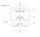
- 1 is a flow chart illustrating a method for producing metal carbide according to the present disclosure.
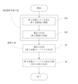
- 1 is a flow chart illustrating a method for producing hydrocarbons according to the present disclosure.
- 1 is a photograph showing the appearance of a working electrode before an electrolysis step in Example 6-1.
- 1 is a photograph showing the appearance of the working electrode after the electrolysis step of Example 6-1.
- 1 is a cross-sectional photograph of a deposit deposited on a working electrode after an electrolysis step in Example 6-1.
- 1 is a photograph showing the appearance of the working electrode after the electrolysis step of Example 6-2.
- 1 is an optical microscope photograph of a cross section of a deposit deposited on a working electrode after an electrolysis step in Example 6-2, observed using a micro-Raman spectroscopic analyzer.
- 1 is a graph showing the results of Raman spectroscopy of the precipitate obtained in Example 6-2.
- a voltage is applied to a molten salt containing at least one first metal ion selected from the group consisting of alkali metal ions and alkaline earth metal ions and carbonate ions derived from carbon dioxide to cause a first precipitate containing carbon to precipitate on a first electrode made of SUS304, thereby obtaining a second electrode (electrode preparation step).
- metal carbide is obtained by electrolysis using the first molten salt used in the electrode preparation step as it is, with the carbon precipitated on the second electrode as a carbon source (electrolysis step).
- the first molten salt used in the electrode preparation process is used as it is in the next electrolysis process, that is, the electrode preparation process and the electrolysis process are performed in the same electrolytic bath, so productivity is high.
- This embodiment involves hydrolyzing the metal carbide obtained by the above method to obtain hydrocarbons. This method makes it possible to efficiently obtain high-purity hydrocarbons.
- This embodiment includes a carbon-containing member carrying a metal carbide.
- This carbon-containing member can be used to produce hydrocarbons.
- the method for producing metal carbide according to the present disclosure includes an electrode preparation step including preparing a first molten salt containing at least one first metal ion selected from the group consisting of alkali metal ions and alkaline earth metal ions and carbonate ions, and applying a voltage to the first molten salt to cause a precipitate containing carbon to precipitate on the first electrode to obtain a second electrode, and an electrolysis step including applying a voltage to a second molten salt containing at least one second metal ion selected from the group consisting of alkali metal ions and alkaline earth metal ions using the second electrode to obtain a carbide composition containing a carbide of the second metal.
- Electrode Preparation Step In the electrode preparation step, a carbon-containing deposit is deposited on a first electrode to prepare a second electrode.
- the carbon on the second electrode is used as a carbon source for producing metal carbide in the electrolysis step.
- the carbon-containing deposit is deposited on the surface of the electrode with a lower potential (cathode).
- the first electrode may be referred to as the "cathode” and the other electrode may be referred to as the "anode”.
- the electrode preparation process includes preparing a first molten salt containing at least one first metal ion selected from the group consisting of alkali metal ions and alkaline earth metal ions and carbonate ions, and applying a voltage to the first molten salt to cause a first precipitate containing carbon to precipitate on the first electrode, thereby obtaining a second electrode.
- first molten salt containing a first metal ion and a carbonate ion derived from carbon dioxide is prepared.
- the first metal ion is generated by ionizing the salt of the first metal.
- the carbonate ion is generated by adding a gas containing carbon dioxide to the electrolytic bath. In the first molten salt, it is not necessary that the first metal salt and the carbon dioxide are all ionized.
- the salt of the first metal contained in the electrolytic bath is referred to as the first metal salt even if it is completely ionized
- the molten salt prepared from the first metal salt and carbon dioxide is referred to as the first molten salt even if they are not completely ionized.
- the first metal ion is at least one selected from the group consisting of alkali metal ions and alkaline earth metal ions.
- the alkali metal ions and alkaline earth metal ions have excellent electrolyte functions.
- the alkali metal may be at least one selected from the group consisting of lithium (Li), sodium (Na), potassium (K), rubidium (Rb), cesium (Cs) and francium (Fr).
- the alkali metal may be at least one selected from the group consisting of Li, Na, K, Rb and Cs.
- the alkali metal may in particular be at least one selected from the group consisting of Li, Na, K and Cs.
- the alkaline earth metal may be at least one selected from the group consisting of beryllium (Be), magnesium (Mg), calcium (Ca), strontium (Sr), barium (Ba) and radium (Ra).
- the alkaline earth metal may be at least one selected from the group consisting of Mg, Ca, Sr and Ba.
- the first molten salt may contain a metal ion (a third metal ion) other than the first metal ion. It is preferable that the salt of the third metal ion ionizes at a temperature of 800° C. or lower.
- the third metal may be, for example, at least one selected from the group consisting of rare earth elements, aluminum (Al), gallium (Ga), indium (In), thallium (Tl), zinc (Zn), cadmium (Cd), gold (Au), silver (Ag) and copper (Cu).
- the rare earth elements may be scandium (Sc), yttrium (Y), lanthanide elements and actinide elements.
- Carbonate ions are generated by adding a gas containing carbon dioxide to the electrolytic bath.
- a gas containing carbon dioxide (hereinafter, sometimes referred to as CO2 gas) is brought into contact with the first metal salt in a liquid state in a gaseous state.
- the CO2 gas may be blown into the gas phase of the electrolytic bath to contact the liquid surface of the first metal salt, or the CO2 gas may be blown into the first metal salt.
- the CO2 gas may be a mixed gas of CO2 and an inert gas (typically argon).
- a sufficient amount of CO2 gas may be added to the first metal salt before the voltage is applied, or the CO2 gas may be added to the first metal salt while the voltage is being applied.
- the amount of CO2 gas blown in may be appropriately set depending on the amount of the first metal ion.
- the amount of CO2 gas blown in is equal to or greater than the equivalent amount of the first metal salt, taking into account the efficiency of absorption of the gas into the first metal salt.
- the bubble diameter of the CO2 gas to be blown in is small.
- the bubble diameter of the CO2 gas is preferably 10 mm or less, more preferably 1 mm or less.
- the bubble diameter of the CO2 gas may be 100 nm or more, or 1 ⁇ m or more.
- the bubble diameter of the CO2 gas can be made fine by, for example, bubbling through a porous material made of quartz glass or high-purity alumina, stirring with a stirrer, applying vibration, or irradiating with ultrasonic waves.
- preheating makes it easier to prevent the first metal salt from being solidified due to a drop in temperature.
- the first molten salt may contain anions other than carbonate ions.
- the other anions include at least one selected from the group consisting of halide ions, sulfate ions, phosphate ions, nitrate ions, acetate ions, carboxylate ions, and oxide ions (O 2 ⁇ ).
- the other anions may include halide ions derived from a halide of the first metal.
- a halide of the first metal is commonly used as a molten salt and is excellent as an electrolyte.
- the first metal is Ca
- calcium carbide CaC2
- Metallic calcium may also be produced on the cathode (Formula 4). A part or all of the metallic lithium produced by this side reaction may further react to become calcium carbide (Formula 5).
- metallic calcium may react with carbon dioxide physically dissolved in the first molten salt to become calcium carbide (Formula 6). Carbon powder may be produced, causing the molten salt to become black and turbid (Formula 7).
- the CaO produced in the above (Formula 6) and (Formula 7) immediately dissolves in the molten salt to produce calcium ions and oxide ions (Formula 8).
- the first metal is Na, K or Li
- sodium carbide (Na 2 C 2 ) potassium carbide (K 2 C 2 ) or lithium carbide (LiC 2 ) precipitates together with carbon by a similar reaction.
- Na 2 C 2 sodium carbide
- K 2 C 2 potassium carbide
- LiC 2 lithium carbide
- O 2- is oxidized to generate oxygen.
- the oxygen generated at the anode is discharged into the gas phase. This oxygen gas can be collected and used for other purposes.
- the voltage is applied at a temperature at which the first molten salt can be maintained in a molten state.
- the temperature of the electrolytic bath may be, for example, 350°C or higher, or 400°C or higher.
- the temperature of the electrolytic bath may be, for example, 800°C or lower, or 700°C or lower. According to the present disclosure, the reaction proceeds at such a relatively low temperature, resulting in high energy efficiency.
- the applied voltage is set so that the first electrode (cathode) potential is equal to or lower (lower) than the potential (Ec) at which carbon precipitates.
- the current value may be set appropriately according to the amount of CO 2 supplied per unit time. For example, the current value is set so that the amount of CO 3 2- produced by the reaction between CO 2 and O 2 - in the first molten salt is greater than the amount of CO 3 2- consumed per unit time at the cathode, so that the concentration of CO 3 2- in the first molten salt does not decrease.
- a cathode made of SUS304 is used. This greatly improves the Faraday efficiency. SUS304 is also desirable because it is relatively easy to obtain, inexpensive, and has excellent heat resistance. SUS304 is an austenitic stainless steel, and its composition is described in JIS G 4303, etc.
- the material of the cathode is not limited to SUS304.
- the cathode material include metals such as Ag, Cu, Ni, Pb, Hg, Tl, Bi, In, Sn, Cd, Au, Zn, Ga, Ge, Fe, Pt, Pd, Ru, Ti, Cr, Mo, W, V, Nb, Ta, Zr, and alloys of these metals.
- Specific examples of alloys include ferritic stainless steels such as SUS430.
- the cathode may contain at least one selected from the group consisting of transition metals and alloys containing transition metals.
- transition metals Ni, Fe, Mo, and Ti may be used.
- the cathode may particularly contain an iron alloy (typically, stainless steel) or may be formed from an iron alloy.
- the cathode may contain SUS304 or may be formed from SUS304.
- the material of the anode is not particularly limited.
- Examples of the material of the anode include Pt, conductive metal oxide, glassy carbon, natural graphite, isotropic graphite, pyrolytic graphite, plastic formed carbon, and boron-doped diamond.
- Examples of the electrode made of conductive metal oxide include a transparent conductive electrode called an ITO electrode in which a mixed oxide of indium and tin is formed on glass, an electrode called a DSA electrode (a trademark of De Nora Permelec Electrodes, Inc.) in which an oxide of a platinum group metal such as ruthenium or iridium is formed on a substrate such as titanium, and a conductive metal oxide electrode having a composition such as La 1-x Sr x FeO 3- ⁇ (0 ⁇ x ⁇ 0.5 (particularly, 0.1 ⁇ x ⁇ 0.5), 0 ⁇ 0.5).
- a conductive metal oxide-based anode is preferable in that it is less likely to be consumed by oxidation reaction.
- the electrode preparation process produces a second electrode carrying a carbon-containing precipitate.
- Electrolysis process (S2) In the electrolysis step, the second electrode obtained in the electrode preparation step is used to electrolyze a second molten salt containing at least one second metal ion selected from the group consisting of alkali metal ions and alkaline earth metal ions. As a result, a carbide composition containing carbide of the second metal is obtained using the carbon supported on the second electrode as a carbon source.
- the second metal ion is at least one selected from the group consisting of alkali metal ions and alkaline earth metal ions.
- the second metal ion is a metal source for the target metal carbide.
- the carbides of alkali metals and alkaline earth metals, also called acetylides, are easy to produce acetylene by hydrolysis and have high industrial value.
- the alkali metal ions and alkaline earth metal ions have excellent functions as electrolytes.
- the second metal ion may include an alkaline earth metal ion, and may include Ca ions.
- the second metal ion may include an alkali metal ion together with an alkaline earth metal ion. This is because the alkali metal ion has excellent electrolyte functions, such as facilitating ionization of the alkaline earth metal salt, promoting the generation of alkaline earth metal ions, lowering the melting point of the molten salt, and enabling electrolysis at a lower temperature.
- the first metal ion may include at least one alkali metal ion selected from the group consisting of Li, Na, K, Rb, and Cs ions, and at least one alkaline earth metal ion selected from the group consisting of Be, Mg, Ca, Sr, and Ba ions. In particular, it may include at least one Li, Na, and K ion, and Ca ions.
- the amount of the second metal ion contained in the second molten salt is not particularly limited. Since the second metal ion is the metal source of the target metal carbide, it is desirable that a sufficient amount is contained.
- the number of moles of the second metal ion may be 1 mol% or more, 2 mol% or more, or 3 mol% or more, relative to the total number of moles of cations in the electrolytic bath.
- the number of moles of the second metal ion may be 20 mol% or less, 15 mol% or less, or 10 mol% or less, relative to the total number of moles of cations in the electrolytic bath. In one embodiment, the number of moles of the second metal ion is 1 mol% or more and 20 mol% or less, relative to the total number of moles of cations in the electrolytic bath.
- a second metal ion may be further added to the electrolytic bath before the electrolysis process.
- Examples of the counter ion (anion) of the second metal ion include at least one selected from the group consisting of a halide ion, a sulfate ion, a phosphate ion, a nitrate ion, an acetate ion, a carboxylate ion, and an oxide ion (O 2 ⁇ ).
- the second molten salt may contain at least one of halide ions and oxide ions as anions.
- the second molten salt may contain both halide ions and oxide ions.
- oxides of the second metal are easy to obtain, their melting temperature tends to be high.
- Halides of the second metal are commonly used as molten salts.
- halide ions can generate halogen gas at the anode, which has a high oxidizing power (and can cause corrosion).
- the molten salt contains both halide ions and oxide ions, it is possible to lower the melting temperature of the molten salt while suppressing the generation of halogen gas.
- the halogen may be at least one selected from the group consisting of fluorine (F), chlorine (Cl), bromine (Br), iodine (I) and astatine (At).
- the halogen may be at least one selected from the group consisting of F, Cl, Br and I, and may in particular be F and/or Cl.
- the second molten salt does not substantially contain carbonate ions (CO 3 2 ⁇ ). If the second molten salt contains carbonate ions, they react with electrons generated by the discharge of the second metal (Formula 7) and tend to produce carbon. This reduces the yield of the second metal carbide. By making the second molten salt substantially free of carbonate ions, such side reactions are suppressed, and the yield of the second metal carbide is increased. (Formula 7) 2CO 3 2- +8e - ⁇ 2C+6O 2-
- the second molten salt may contain, for example, about 1.0 mol% or less of carbonate ions.
- the carbonate ion concentration in the second molten salt may be 0.5 mol% or less, 0.3 mol% or less, or 0 mol%.
- the second metal salt containing an alkaline earth metal ion include CaO, CaCl2 , CaF2 , CaBr2 , CaI2 , CaH2 , and Ca3P2 .
- Specific examples of the second metal salt containing an alkali metal ion include LiF, NaF, KF, RbF, CsF, LiCl, NaCl, KCl, RbCl, CsCl, LiBr, NaBr, KBr, RbBr , CsBr, LiI, NaI, KI, RbI, and CsI.
- the second metal ion may be the same as the first metal ion or may be different.
- the first metal ion and the second metal ion may be the same.
- the first molten salt used in the electrode preparation process is used as the second molten salt in the electrolysis process, so the second metal ion may contain the same type of metal ion as the first metal ion.
- the material of the other electrode is not particularly limited. Examples of anode materials include those similar to those used in the electrode fabrication process. In this embodiment, the anode used in the electrode fabrication process may be used as is in the electrolysis process.
- the second metal ions When a voltage is applied to the second molten salt, the second metal ions are reduced on the carbon constituting the cathode (second electrode) to produce the second metal, which immediately reacts with the carbon constituting the cathode (second electrode) to produce a composition containing the second metal carbide (metal carbide composition). If there is a second metal salt that has not been ionized in the second molten salt, the application of a voltage can also promote ionization of the second metal salt.
- the voltage is applied at a temperature at which the molten salt can be maintained in a molten state.
- the temperature of the electrolytic bath may be, for example, 350°C or higher, or 400°C or higher.
- the temperature of the electrolytic bath may be, for example, 800°C or lower, or 700°C or lower. According to the present disclosure, the reaction proceeds at such a relatively low temperature, resulting in high energy efficiency.
- the applied voltage is set so that the cathode potential is lower (more noble) than the potential (Emc) at which the second metal precipitates on the cathode. This can further improve the selectivity of the second metal carbide. If the cathode potential is excessively high (more noble), the amount of the desired second metal carbide produced is likely to decrease. If the cathode potential is excessively low (more noble), the second metal carbide is produced, but the metal contained in the molten salt that has the most noble redox potential in the molten salt is primarily precipitated. If the molten salt contains multiple metals with similar redox potentials in the molten salt, an alloy of multiple metals may precipitate.
- the potential Emc can be determined by performing cyclic voltammetry measurements in the molten salt to be used, using the metal electrode to be used, for example, a SUS304 electrode.
- the set current value should be set appropriately so that the cathode potential during electrolysis is within the potential range described above.
- the metal carbide composition is usually obtained in a state supported on the cathode (strictly speaking, on the substrate derived from the first (second) electrode that was used as the cathode).
- the second metal carbide is obtained in a state where it is partially or entirely dissolved in the molten salt. If the second metal carbide is dissolved in the molten salt in advance, the second metal carbide obtained by electrolysis is more likely to be deposited on the cathode and is more likely to be obtained in a state where it is supported on the substrate derived from the first electrode.
- the metal carbide composition includes a carbide of a second metal.
- the second metal carbide is the main component of the metal carbide composition.
- the main component is a component that accounts for 50 mass% or more of the total mass of the metal carbide composition.
- the content of the second metal carbide may be 80 mass% or more, or may be 90 mass% or more, of the mass of the metal carbide composition.
- the content of the second metal carbide may be 99.9 mass% or less, or may be 99 mass% or less, of the mass of the metal carbide composition. In one embodiment, the content of the second metal carbide is 80 mass% or more and 99.9 mass% or less of the mass of the metal carbide composition.
- the metal carbide composition may contain at least one by-product selected from the group consisting of carbon, an elemental substance of the second metal, a halide, a carbonate, an oxide, a hydride, and a peroxide.
- the metal carbide composition may further contain at least one by-product selected from the group consisting of an elemental substance of the first metal, a halide, a carbonate, an oxide, and a carbide.
- the metal carbide composition may also contain at least one selected from the group consisting of solidified electrolytes (other metal salts), halides, oxides, metals, and hydrates of the materials that make up the device.
- the carbon contained in the metal carbide composition is at least one selected from the group consisting of nanocarbon materials such as graphite, amorphous carbon, glassy carbon, carbon nanotubes, diamond, nanodiamond, graphene, etc.
- nanocarbon materials such as graphite, amorphous carbon, glassy carbon, carbon nanotubes, diamond, nanodiamond, graphene, etc.
- the presence and quantification of the second metal carbide, the second metal itself, compounds containing the second metal, and other by-products can be performed, for example, by Raman spectroscopy and X-ray diffraction (XRD) analysis of the composition.
- XRD X-ray diffraction
- the present disclosure encompasses a carbon-containing component comprising a substrate and a metal carbide composition supported on the substrate, the metal carbide composition comprising a carbide of at least one second metal selected from the group consisting of alkali metals and alkaline earth metals.
- the carbon-containing component according to the present disclosure can be utilized in the production of hydrocarbons.
- the carbon-containing member can be obtained, for example, by the above-mentioned method for producing metal carbide. That is, the carbon-containing member can correspond to the second electrode used in the electrolysis of the second molten salt. In this case, the substrate is derived from the second electrode.
- the metal carbide composition may be supported on at least a portion of the surface of the substrate.
- the surface of the substrate typically corresponds to the portion of the second electrode that was in contact with the second metal ion. Supported includes a state in which at least a portion of the surface of the substrate is coated with the metal carbide composition.
- the present disclosure includes a method for producing hydrocarbons from a second metal carbide. That is, the method for producing hydrocarbons according to the present disclosure includes the above-mentioned electrode preparation step, electrolysis step, and hydrolysis of the second metal carbide to obtain a gas containing hydrocarbons.
- Figure 2 is a flow chart showing the method for producing hydrocarbons according to the present disclosure.
- Electrode preparation process (S11, S12) The second electrode is produced in the same manner as in the electrode production steps (S11 and S12) in the above-mentioned method for producing metal carbide.
- the second metal carbide may be isolated from the metal carbide composition and hydrolyzed. Isolation is performed, for example, by crushing the metal carbide composition and utilizing the difference in specific gravity. Alternatively, the metal carbide composition may be hydrolyzed as is. For example, an electrode on which the metal carbide composition has been precipitated (which may be the "carbon-containing member" according to the present disclosure) is brought into contact with water as is.
- hydrocarbons examples include methane, ethane, ethylene, acetylene ( C2H2 ), methylacetylene, propane, propylene, butane , and butene.
- acetylene is obtained as the main component.
- the main component is a component that accounts for 50% by mass or more of the total mass of the gas recovered.
- Acetylene is an industrially important hydrocarbon.
- the gas obtained may contain water vapor, hydrogen, nitrogen, and oxygen as by-products in addition to hydrocarbons.
- the amount of by-products is preferably 10% by mass or less of the gas recovered, and more preferably 1% by mass or less.
- the amount of by-products may be 0.0001% by mass or more of the gas recovered, or may be 0.001% by mass or more. In one embodiment, the amount of by-products is 0.0001% by mass or more and 1% by mass or less of the gas recovered.
- the resulting gas contains acetylene as a hydrocarbon, and may further contain at least one selected from the group consisting of ethylene, ethane, methane, methylacetylene, propylene, butene, and hydrogen.
- GC-MS analysis gas chromatography mass spectrometry
- FT-IR analysis Fourier transform infrared absorption spectrometry
- UV-Vis analysis ultraviolet-visible absorption spectrometry
- the amount of water to be brought into contact with the composition is appropriately set depending on the mass of the composition.
- the amount of water is, for example, at least the amount necessary for hydrolysis of the metal carbide and metal contained in the composition.
- Hydrolysis of the second metal carbide produces a hydroxide of the second metal along with the hydrocarbons.
- the hydrolysis of calcium carbide produces calcium hydroxide along with acetylene (Equation 10).
- Equation 10 CaC 2 +2H 2 O ⁇ C 2 H 2 +Ca(OH) 2
- Second embodiment differs from the first embodiment in that the electrolytic bath used in the electrode preparation step and the electrolysis step is different. This difference will be described below.
- the other configurations of the method for producing metal carbide are the same as those in the first embodiment, so their description will be omitted.
- the method for producing hydrocarbons and the configuration of the carbon-containing member are the same as those in the first embodiment, so their description will be omitted.
- a second molten salt prepared separately from the first molten salt used in the electrode preparation process is used in the electrolysis process.
- carbonate ions which were the carbon source, remain in the first molten salt used in the electrode preparation process.
- a second molten salt that is substantially free of carbonate ions can be prepared, which suppresses side reactions and can further improve the yield and faradaic efficiency of the second metal carbide.
- Third embodiment differs from the first embodiment in the material of the first electrode. This difference will be described below.
- the other configurations of the method for producing metal carbide are the same as those of the first embodiment, so their description will be omitted.
- the method for producing hydrocarbons and the configuration of the carbon-containing member are the same as those of the first embodiment, so their description will be omitted.
- an Fe plate is used as the first electrode.
- a carbon-containing member can be formed that includes a substrate, a metal carbide layer that covers at least a portion of the substrate and contains at least one carbide of a second metal selected from the group consisting of alkali metals and alkaline earth metals, and a carbon layer that covers at least a portion of the metal carbide layer, contains carbon, and is substantially free of the second metal carbide.
- a carbon-containing member can suppress decomposition of carbide even when stored in a humid atmosphere. The presence or absence of the second metal carbide can be confirmed, for example, by Raman spectroscopy.
- the carbon layer may contain, for example, about 10,000 ppm or less of second metal carbide.
- the second metal carbide concentration in the carbon layer may be 1000 ppm or less, 500 ppm or less, or 0 ppm.
- carbon dioxide is used as the carbonate ion source, but the present invention is not limited to this.
- the carbonate ion source may be a carbonate of any metal.
- the first metal ion and carbonate ion are generated by ionization.
- the carbonate of the first metal can be synthesized, for example, by reacting a hydroxide of the first metal with carbon dioxide.
- an electrode made of SUS304 or Fe is used as the first electrode (cathode), but this is not limited to this.
- the first electrode may contain other metal materials and may be formed from a carbon material.
- the first electrode may also contain carbon materials such as glassy carbon, natural graphite, isotropic graphite, pyrolytic graphite, plastic formed carbon, and conductive diamond, and may be formed from a carbon material.
- the carbon-containing member obtained comprises, but is not limited to, a substrate and a metal carbide composition containing a carbide of a second metal supported on the substrate.
- the carbon-containing member obtained by the method shown in the first embodiment may comprise a substrate, a metal carbide layer, and a carbon layer.
- the carbon-containing member obtained includes, but is not limited to, a substrate, a metal carbide layer, and a carbon layer.
- the carbon-containing member obtained by the method shown in the third embodiment may include a substrate and a metal carbide composition that includes a carbide of a second metal supported on the substrate.
- the mixed salts were placed in quartz containers, set in an electric furnace, and heated to 450°C. In this way, a molten salt of LiCl-KCl-CaCl- CaO was obtained.
- a working electrode (1.0 cm x 1.0 cm, SUS304), a counter electrode (platinum coil) and a reference electrode (Ag + /Ag) were attached to the lid of the container, and the container was sealed with the lid.
- CO 2 was blown into the molten salt at 450 ° C. in the container at a flow rate of 100 mL / min for 30 minutes or more.
- a voltage was applied for 30 minutes using a potentio-galvanostat while maintaining the potential of the working electrode relative to the reference electrode at 0.9 V. It was confirmed that a precipitate was deposited on the working electrode. All experimental operations were performed in a glove box maintained in a high-purity argon atmosphere.
- Electrolysis step Subsequently, electrolysis was performed using the same electrolytic bath and electrodes. Specifically, a voltage was applied for 30 minutes using a potentio-galvanostat while maintaining the potential of the working electrode relative to the reference electrode at 0.3 V. It was confirmed that a deposit was deposited on the working electrode. All experimental operations were performed in a glove box that maintained a high-purity argon atmosphere. The potential of the working electrode was a value obtained by measuring the potential between the reference electrode (Ag + /Ag) and the cathode and calibrating it based on the Li-Ca alloy deposition potential.
- the obtained gas was subjected to GC-MS analysis, and it was confirmed that C 2 H 2 was produced as the main component. Furthermore, it was confirmed that methane, ethane, and hydrogen were by-produced. In addition, water, carbon dioxide, nitrogen, oxygen, and argon were contained. The amount of each component produced was also confirmed. The mass ratio of C 2 H 2 in the recovered gas was sufficiently more than 50 mass%.
- the Faraday efficiency of C2H2 gas generation through the electrode preparation process and the electrolysis process was calculated to be about 2.2 %. Since C2H2 gas was generated, it can be understood that the precipitate contains CaC2 as a main component. It can be said that the higher the Faraday efficiency of hydrocarbon gas generation, the higher the Faraday efficiency of metal carbide generation.
- Example 1-2 Electrolysis and hydrolysis were performed in the same manner as in Example 1-1, except that the potential of the working electrode relative to the reference electrode was maintained at 0.6 V in the electrode preparation step and at 0.1 V in the electrolysis step.
- Example 2-1 The potential of the working electrode relative to the reference electrode was maintained at 0.3 V in the electrode preparation step, and at 0.1 V in the electrolysis step. In addition, in the electrolysis step, the electrode was not changed, and a separately prepared electrolytic bath was used. Other than these, electrolysis and hydrolysis were performed in the same manner as in Example 1-1. The electrolytic bath used in the electrolysis step was prepared in the same manner as in Example 1-1.
- Example 2-2 Electrolysis and hydrolysis were performed in the same manner as in Example 2-1, except that the potential of the working electrode relative to the reference electrode was maintained at 0.1 V in the electrode preparation step and at 0.1 V in the electrolysis step.
- Example 3-1 The potential of the working electrode relative to the reference electrode was maintained at 0.3 V in the electrode preparation step and the electrolysis step. The electrolysis step was also carried out in a CO2 atmosphere. Except for these, electrolysis and hydrolysis were carried out in the same manner as in Example 1-1.
- Example 3-2 Electrolysis and hydrolysis were carried out in the same manner as in Example 3-1, except that the potential of the working electrode relative to the reference electrode was maintained at 0.1 V in the electrode preparation step and the electrolysis step.
- Example 4-1 The potential of the working electrode relative to the reference electrode was maintained at 0.3 V in the electrode preparation step, and was maintained at 0.1 V in the electrolysis step.
- electrolysis and hydrolysis were performed in the same manner as in Example 3-1, except that after the electrode preparation step, the electrode was temporarily removed from the electrolysis bath, and after 30 minutes, the electrode was placed in the same bath again to perform the electrolysis step.
- Example 4-2 Electrolysis and hydrolysis were carried out in the same manner as in Example 4-1, except that the potential of the working electrode relative to the reference electrode was maintained at 0.1 V in the electrode preparation step and the electrolysis step.
- Examples 5-1 to 5-49 Except for changing the composition of the molten salt, the material of the cathode, and the electrolysis conditions as shown in Tables 5 and 6, the electrode preparation step and hydrolysis were performed in the same manner as in Example 1-1.
- Examples 5-23 to 5-49 the potential of the working electrode was measured by measuring the potential between the reference electrode (Ag + /Ag) and the cathode, and was calibrated based on the Na-K-Ca alloy deposition potential.
- 7.0 mol% of CaC2 was added to the molten salt in advance.
- the Faraday efficiency in the table is a value related to the generation of C2H2 gas by the precipitate deposited in the electrode preparation process. The larger this Faraday efficiency, the greater the amount of CaC2 deposited in the electrode preparation process. It can be said that if the Faraday efficiency related to the generation of C2H2 gas in the electrode preparation process is large, the Faraday efficiency related to the generation of C2H2 gas through the electrode preparation process and the electrolysis process will also be large. Since C2H2 gas is generated , it can be understood that the precipitate deposited on the working electrode by the electrolysis process contains CaC2 as a main component.
- Example 6-1 Electrolysis and hydrolysis were carried out in the same manner as in Example 5-45, except that the accumulated amount of electricity was set to 2000C.
- the precipitate deposited on the working electrode by the electrode preparation process contained polycrystalline C as the main component and CaC2 as a by-product.
- Figure 3A is a photograph showing the appearance of the working electrode before the electrolysis process in Example 6-1.
- Figure 3B is a photograph showing the appearance of the working electrode after the electrolysis process in Example 6-1.
- a black precipitate can be seen on the surface of the working electrode, and it can be seen that it has swelled to more than double its size.
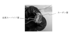
- Figure 3C is a cross-sectional photograph of the precipitate deposited on the working electrode after the electrolysis process in Example 6-1. From Figure 3C, it was confirmed that the precipitate has a layered structure.
- the inner layer is a metal carbide layer mainly composed of calcium carbide
- the outer layer is a carbon layer that contains carbon but does not substantially contain calcium carbide.
- FIG. 4A is a photograph showing the appearance of the working electrode after the electrolysis step of Example 6-2.
- FIG. 4B is an optical microscope photograph of a cross section of a deposit deposited on the working electrode after the electrolysis step of Example 6-2, observed using a micro-Raman spectroscopic analyzer.
- FIG. 4B also shows a schematic cross-sectional view of the working electrode after the electrolysis step. The optical microscope photograph corresponds to the part surrounded by a square in the schematic cross-sectional view.
- point A indicates the black part outside the deposit
- point B indicates the gray part inside the deposit
- point C indicates the Fe substrate of the working electrode. It was confirmed from FIG. 4B that the deposit has a layer structure.
- Figure 4C is a graph showing the results of Raman spectroscopy analysis at points A to C. From these results, it was confirmed that the inside of the precipitate (point B) is a metal carbide layer mainly composed of calcium carbide, and the outside of the precipitate (point A) is a carbon layer that contains carbon but is substantially free of calcium carbide.
- a working electrode (1.0 cm x 1.0 cm, Fe), a counter electrode (platinum) and a reference electrode (Ag + /Ag) were attached to the lid of the container, and the container was sealed with the lid.
- CO 2 was blown into the molten salt at 550 ° C. in the container at a flow rate of 100 mL / min for 60 minutes or more.
- a voltage was applied for 30 minutes while maintaining the potential of the working electrode with respect to the reference electrode at 0.3 V using a potentio-galvanostat.
- the potential of the working electrode was a value obtained by measuring the potential between the reference electrode (Ag + /Ag) and the cathode and calibrating it based on the Na-K-Ca alloy deposition potential.
- Electrolysis step Subsequently, electrolysis was performed using an electrolytic bath having the same composition as above and the electrode obtained in the electrode preparation step, which were separately prepared. Specifically, a voltage was applied for 30 minutes using a potentio-galvanostat while maintaining the potential of the working electrode relative to the reference electrode at 0.3 V. It was confirmed that a deposit was deposited on the working electrode.
- the experimental operation was performed in a glove box that maintained a high-purity argon atmosphere, including the gas phase portion in the container.
- C 2 H 2 was generated as the main component. Since C 2 H 2 gas was generated, it can be understood that the deposit deposited on the working electrode by the electrolysis process contains CaC 2 as the main component. Furthermore, it was confirmed that methane, ethane, and hydrogen were by-produced. In addition, it contained water, carbon dioxide, nitrogen, oxygen, and argon. The amount of each component generated was also confirmed. The mass ratio of C 2 H 2 in the recovered gas was sufficiently more than 50 mass%.
- the Faraday efficiency of C2H2 gas generation throughout the electrode preparation process and the electrolysis process was calculated to be about 42.8 %. Since C2H2 gas was generated, it can be understood that the precipitate contains CaC2 as a main component.
- Example 7-2 to 7-6 Electrolysis and hydrolysis were carried out in the same manner as in Example 7-1, except that the electrolysis conditions were changed as shown in Table 7.
- Example 8-1 to 8-6 The electrolysis conditions were changed as shown in Table 7, and electrolysis and hydrolysis were performed in the same manner as in Example 7-1, except that CaC2 was added to the molten salt in an amount of 1.0 mol% relative to the molten salt during the electrolysis process.
- Table 7 shows the Faraday efficiency of C2H2 gas generation through the electrode preparation process and the electrolysis process. Since C2H2 gas was generated, it can be understood that the deposit deposited on the working electrode by the electrolysis process contains CaC2 as a main component.
- Example 9-1 to 9-6 The electrolysis conditions were changed as shown in Table 7, and electrolysis and hydrolysis were performed in the same manner as in Example 7-1, except that CaC2 was added to the molten salt in an amount of 7.0 mol% relative to the molten salt during the electrolysis process.
- Table 7 shows the Faraday efficiency of C2H2 gas generation through the electrode preparation process and the electrolysis process. Since C2H2 gas was generated, it can be understood that the deposit deposited on the working electrode by the electrolysis process contains CaC2 as a main component.
- Examples 10-1 to 10-3 After the electrode preparation process, the electrodes were removed from the bath, and after 30 minutes, they were placed in the same bath again to carry out the electrolysis process. Except for this, electrolysis and hydrolysis were carried out in the same manner as in Examples 7-1, 7-3, and 7-5.
- the electrolysis conditions were as shown in Table 7, and the electrolysis process was carried out in a CO2 atmosphere.
- Table 7 shows the Faraday efficiency of C2H2 gas generation through the electrode preparation process and the electrolysis process. Although the amount of C2H2 gas generated was not measured, it can be understood that the deposit deposited on the working electrode by the electrolysis process contains CaC2 as a main component, since the Faraday efficiency was 0.1% or more in both cases.
- the faradaic efficiency e for C 2 H 2 production was calculated as follows. First, the volume ratio of C2H2 contained in the collected gas was calculated from the total area of the peaks obtained from the GC-MS analysis and the calibration curve. Next, the volume of C2H2 generated was calculated from the volume of the gas phase in the collection vessel and the calculated volume ratio of C2H2 in the gas . Finally, the Faraday efficiency e (%) was calculated by the following formula, assuming that the generated C2H2 was in standard conditions (0°C, 101 kPa).
- the desired second metal carbide was obtained with high faradaic efficiency by either electrolysis method.
- the series of Examples 2, 3, and 4 had higher faradaic efficiency. This indicates that carbon was sufficiently precipitated because the potential in the electrode preparation process was base.
- the series of Example 2 had a very high faradaic efficiency. This is thought to be because the electrolysis process was performed in an Ar atmosphere and the electrolytic bath was changed between the electrode preparation process and the electrolysis process, resulting in a low carbonate ion concentration in the second molten salt.
- the manufacturing method disclosed herein is useful in a variety of fields because the reaction proceeds quickly at relatively low temperatures and metal carbide can be obtained efficiently.
Landscapes
- Chemical & Material Sciences (AREA)
- Organic Chemistry (AREA)
- Engineering & Computer Science (AREA)
- Chemical Kinetics & Catalysis (AREA)
- Electrochemistry (AREA)
- Materials Engineering (AREA)
- Metallurgy (AREA)
- Inorganic Chemistry (AREA)
- Oil, Petroleum & Natural Gas (AREA)
- Electrolytic Production Of Metals (AREA)
- Electrolytic Production Of Non-Metals, Compounds, Apparatuses Therefor (AREA)
Abstract
Priority Applications (3)
| Application Number | Priority Date | Filing Date | Title |
|---|---|---|---|
| CN202480025108.8A CN120958175A (zh) | 2023-04-12 | 2024-04-03 | 金属碳化物和烃的制造方法以及含碳部件 |
| EP24772195.4A EP4484614A4 (fr) | 2023-04-12 | 2024-04-03 | Procédé de production de carbure métallique et d'hydrocarbure, et élément contenant du carbone |
| US19/355,135 US20260035826A1 (en) | 2023-04-12 | 2025-10-10 | Methods for producing metal carbide and hydrocarbon, and carboncontaining member |
Applications Claiming Priority (4)
| Application Number | Priority Date | Filing Date | Title |
|---|---|---|---|
| JP2023-064934 | 2023-04-12 | ||
| JP2023064934 | 2023-04-12 | ||
| JP2024-048291 | 2024-03-25 | ||
| JP2024048291A JP7583418B2 (ja) | 2023-04-12 | 2024-03-25 | 金属カーバイドおよび炭化水素の製造方法、ならびに炭素含有部材 |
Related Child Applications (1)
| Application Number | Title | Priority Date | Filing Date |
|---|---|---|---|
| US19/355,135 Continuation US20260035826A1 (en) | 2023-04-12 | 2025-10-10 | Methods for producing metal carbide and hydrocarbon, and carboncontaining member |
Publications (1)
| Publication Number | Publication Date |
|---|---|
| WO2024214616A1 true WO2024214616A1 (fr) | 2024-10-17 |
Family
ID=92973353
Family Applications (1)
| Application Number | Title | Priority Date | Filing Date |
|---|---|---|---|
| PCT/JP2024/013769 Ceased WO2024214616A1 (fr) | 2023-04-12 | 2024-04-03 | Procédé de production de carbure métallique et d'hydrocarbure, et élément contenant du carbone |
Country Status (4)
| Country | Link |
|---|---|
| US (1) | US20260035826A1 (fr) |
| EP (1) | EP4484614A4 (fr) |
| CN (1) | CN120958175A (fr) |
| WO (1) | WO2024214616A1 (fr) |
Citations (9)
| Publication number | Priority date | Publication date | Assignee | Title |
|---|---|---|---|---|
| US2952591A (en) * | 1959-02-26 | 1960-09-13 | Union Carbide Corp | Electrolytic preparation of calcium carbide |
| JPS61178412A (ja) | 1985-02-02 | 1986-08-11 | Agency Of Ind Science & Technol | 溶鉱炉法による炭化カルシウムの製造方法 |
| JPH02256626A (ja) | 1988-08-25 | 1990-10-17 | Taiyo Sanso Co Ltd | 高純度アセチレンガスの製造方法 |
| JP2018035328A (ja) | 2016-09-02 | 2018-03-08 | デンカ株式会社 | ブリケットの製造方法及びカルシウムカーバイドの製造方法 |
| WO2023058619A1 (fr) * | 2021-10-04 | 2023-04-13 | 学校法人同志社 | Procédé de production de carbure métallique, procédé de production d'hydrocarbure et composition de carbure métallique |
| WO2023058620A1 (fr) * | 2021-10-04 | 2023-04-13 | 学校法人同志社 | Procédé de production de carbure métallique et d'hydrocarbure, et composition de carbure métallique |
| JP2023064934A (ja) | 2021-10-27 | 2023-05-12 | キヤノン株式会社 | シート給送装置及び画像形成装置 |
| CN116288415A (zh) * | 2023-03-10 | 2023-06-23 | 武汉大学 | 一种电解制备碳化钙的方法 |
| JP2024048291A (ja) | 2022-09-27 | 2024-04-08 | Jfeスチール株式会社 | 連続焼鈍設備、連続焼鈍方法、冷延鋼板の製造方法及びめっき鋼板の製造方法 |
-
2024
- 2024-04-03 WO PCT/JP2024/013769 patent/WO2024214616A1/fr not_active Ceased
- 2024-04-03 EP EP24772195.4A patent/EP4484614A4/fr active Pending
- 2024-04-03 CN CN202480025108.8A patent/CN120958175A/zh active Pending
-
2025
- 2025-10-10 US US19/355,135 patent/US20260035826A1/en active Pending
Patent Citations (9)
| Publication number | Priority date | Publication date | Assignee | Title |
|---|---|---|---|---|
| US2952591A (en) * | 1959-02-26 | 1960-09-13 | Union Carbide Corp | Electrolytic preparation of calcium carbide |
| JPS61178412A (ja) | 1985-02-02 | 1986-08-11 | Agency Of Ind Science & Technol | 溶鉱炉法による炭化カルシウムの製造方法 |
| JPH02256626A (ja) | 1988-08-25 | 1990-10-17 | Taiyo Sanso Co Ltd | 高純度アセチレンガスの製造方法 |
| JP2018035328A (ja) | 2016-09-02 | 2018-03-08 | デンカ株式会社 | ブリケットの製造方法及びカルシウムカーバイドの製造方法 |
| WO2023058619A1 (fr) * | 2021-10-04 | 2023-04-13 | 学校法人同志社 | Procédé de production de carbure métallique, procédé de production d'hydrocarbure et composition de carbure métallique |
| WO2023058620A1 (fr) * | 2021-10-04 | 2023-04-13 | 学校法人同志社 | Procédé de production de carbure métallique et d'hydrocarbure, et composition de carbure métallique |
| JP2023064934A (ja) | 2021-10-27 | 2023-05-12 | キヤノン株式会社 | シート給送装置及び画像形成装置 |
| JP2024048291A (ja) | 2022-09-27 | 2024-04-08 | Jfeスチール株式会社 | 連続焼鈍設備、連続焼鈍方法、冷延鋼板の製造方法及びめっき鋼板の製造方法 |
| CN116288415A (zh) * | 2023-03-10 | 2023-06-23 | 武汉大学 | 一种电解制备碳化钙的方法 |
Non-Patent Citations (2)
| Title |
|---|
| MCENANEY JMROHR BANIELANDER ACSINGH ARKING LANORSKOV JKJARAMILLO TF: "A cyclic electrochemical strategy to produce acetylene from CO , CH , or alternative carbon sources.", SUSTAIN ENERGY FUELS, vol. 4, no. 2, 2020, pages 752 - 2759 |
| UWE RUSCHEWITZ: "Binary and ternary carbides of alkali and alkaline-earth metals", COORDINATION CHEMISTRY REVIEWS, vol. 244, 2003, pages 115 - 136 |
Also Published As
| Publication number | Publication date |
|---|---|
| EP4484614A4 (fr) | 2026-05-06 |
| US20260035826A1 (en) | 2026-02-05 |
| CN120958175A (zh) | 2025-11-14 |
| EP4484614A1 (fr) | 2025-01-01 |
Similar Documents
| Publication | Publication Date | Title |
|---|---|---|
| JP7565049B2 (ja) | 金属カーバイドおよび炭化水素の製造方法、ならびに金属カーバイド組成物 | |
| US12416087B2 (en) | Method for producing metal carbide, method for producing hydrocarbon, and metal carbide composition | |
| JP5532886B2 (ja) | 金属インジウムの製造方法 | |
| JP7583418B2 (ja) | 金属カーバイドおよび炭化水素の製造方法、ならびに炭素含有部材 | |
| WO2024214616A1 (fr) | Procédé de production de carbure métallique et d'hydrocarbure, et élément contenant du carbone | |
| WO2024214618A1 (fr) | Procédé de production de carbure métallique et d'hydrocarbure, et élément contenant du carbone | |
| JP2024152637A (ja) | 金属カーバイドおよび炭化水素の製造方法、ならびに炭素含有部材 | |
| JP7810367B2 (ja) | 金属カーバイドおよび炭化水素の製造方法、ならびに金属含有部材 | |
| WO2025192722A1 (fr) | Procédé de production de carbure métallique et hydrocarbures | |
| WO2023085426A1 (fr) | Cristal de nitrure de carbone cubique et procédé pour le produire | |
| JPS59126783A (ja) | 溶融炭酸ナトリウムから金属ナトリウムを生成する方法 | |
| WO2023161695A1 (fr) | Procédé électrochimique de production d'un carbone nanocristallin ayant une structure 1d, 2d ou 3d et/ou un diamant nanocristallin et/ou un carbone amorphe et/ou un composite de nanomatériau métal-carbone et/ou un mélange de ceux-ci | |
| Kushkhov et al. | Electrodeposition of tungsten and molybdenum metals and their carbides from low-temperature halide-oxide melts | |
| KR100665939B1 (ko) | 염화백금산의 제조 방법과 그 장치 | |
| Kuznetsov et al. | Rhenium Electrochemistry, Chemistry and Electrodeposition from Molten Salts | |
| Grinevitcha et al. | Phase Composition of the Cathodic Products Obtained in Alkali Chloride Melts Containing Potassium Monooxyfluoride Complexes of Tantalum |
Legal Events
| Date | Code | Title | Description |
|---|---|---|---|
| ENP | Entry into the national phase |
Ref document number: 2024772195 Country of ref document: EP Effective date: 20240924 |
|
| 121 | Ep: the epo has been informed by wipo that ep was designated in this application |
Ref document number: 24772195 Country of ref document: EP Kind code of ref document: A1 |
|
| WWE | Wipo information: entry into national phase |
Ref document number: CN2024800251088 Country of ref document: CN |
|
| WWE | Wipo information: entry into national phase |
Ref document number: 202517108448 Country of ref document: IN |
|
| NENP | Non-entry into the national phase |
Ref country code: DE |
|
| WWP | Wipo information: published in national office |
Ref document number: 202517108448 Country of ref document: IN |