WO2024219009A1 - Moissonneuse-batteuse - Google Patents
Moissonneuse-batteuse Download PDFInfo
- Publication number
- WO2024219009A1 WO2024219009A1 PCT/JP2023/044429 JP2023044429W WO2024219009A1 WO 2024219009 A1 WO2024219009 A1 WO 2024219009A1 JP 2023044429 W JP2023044429 W JP 2023044429W WO 2024219009 A1 WO2024219009 A1 WO 2024219009A1
- Authority
- WO
- WIPO (PCT)
- Prior art keywords
- exhaust pipe
- exhaust
- pipe member
- grain storage
- storage tank
- Prior art date
- Legal status (The legal status is an assumption and is not a legal conclusion. Google has not performed a legal analysis and makes no representation as to the accuracy of the status listed.)
- Ceased
Links
Images


Classifications
-
- A—HUMAN NECESSITIES
- A01—AGRICULTURE; FORESTRY; ANIMAL HUSBANDRY; HUNTING; TRAPPING; FISHING
- A01D—HARVESTING; MOWING
- A01D41/00—Combines, i.e. harvesters or mowers combined with threshing devices
- A01D41/12—Details of combines
-
- A—HUMAN NECESSITIES
- A01—AGRICULTURE; FORESTRY; ANIMAL HUSBANDRY; HUNTING; TRAPPING; FISHING
- A01F—PROCESSING OF HARVESTED PRODUCE; HAY OR STRAW PRESSES; DEVICES FOR STORING AGRICULTURAL OR HORTICULTURAL PRODUCE
- A01F12/00—Parts or details of threshing apparatus
- A01F12/60—Grain tanks
Definitions
- the present invention relates to a combine harvester.
- a combine harvester such as that described in Patent Document 1 is known.
- the combine harvester described in Patent Document 1 includes an engine, a machine frame, a threshing device for threshing harvested stalks, and an exhaust pipe for discharging engine exhaust.
- An exhaust port that opens to the outside is formed at the downstream exhaust end of the exhaust pipe.
- the exhaust port is located at a height close to the driver's height, so exhaust air easily reaches the driver.
- the present invention is characterized in that it comprises an engine, a machine frame, a threshing device for threshing harvested stalks, and an exhaust pipe for discharging the exhaust gas from the engine, and an exhaust port that opens to the outside is formed at the downstream exhaust end of the exhaust pipe, and the exhaust port is located below the upper end of the threshing device and above the lower end of the machine frame.
- the exhaust port is located lower than the upper end of the threshing device, so the height of the exhaust port is away from the height of the operator. This makes it difficult for the exhaust to reach the operator. Also, because the exhaust port is located higher than the lower end of the machine frame, soil from the ground is less likely to adhere to the exhaust port.
- the exhaust port opens downward.
- the exhaust port does not open to the rear, so dirt from the ground is less likely to get into the exhaust port. Also, because the exhaust is discharged from the exhaust port toward the ground, the exhaust is less likely to reach the rear of the aircraft.
- the machine is provided with a grain storage section that is arranged adjacent to the threshing device in the left-right direction of the machine body and that stores grains from the threshing device, and that the exhaust pipe is passed between the threshing device and the grain storage section and overlaps with the threshing device and the grain storage section in a side view.
- This characteristic configuration allows the exhaust pipe to be placed in the space between the threshing device and the grain storage section.
- the exhaust pipe overlaps with the grain storage section in a plan view.
- This characteristic configuration allows the exhaust pipe to be placed in the space below the grain storage tank.
- a pair of left and right crawler running devices are provided, and the exhaust port opens toward one of the pair of left and right crawler running devices when viewed in the front-rear direction of the vehicle body.
- the exhaust port opens toward the crawler travel device on the grain storage section side of the pair of left and right crawler travel devices when viewed from the front-rear direction of the machine body.
- the machine frame is configured in a frame shape, and an extension line of the center of the exhaust port passes through the interior of the machine frame and also passes behind one of the crawler traveling devices.
- the exhaust gas discharged from the exhaust port passes through the interior of the machine frame and flows behind one of the crawler running devices. This allows the exhaust gas to flow smoothly from the exhaust port toward the tracks created by one of the crawler running devices.
- a fuel tank is provided behind the threshing device, and the exhaust port opens on the opposite side of the fuel tank in the left-right direction of the machine body.
- the grain storage section is constituted by a grain storage tank
- the threshing device has a grain lifting device provided on the side of the threshing device facing the grain storage tank and transporting the first grains upward toward the grain storage tank
- the exhaust pipe is passed between the grain storage tank and the grain lifting device.
- This characteristic configuration allows the exhaust pipe to be placed in the space between the grain storage tank and the grain lifting device.
- the exhaust port is located rearward of the grain lifting device.
- the exhaust air is discharged from the exhaust port at a position behind and away from the grain lifting device. This makes it difficult for the exhaust air to reach the grain lifting device.
- a grain discharge device is provided that is erected behind the grain storage tank and discharges the grains in the grain storage tank, and it is preferable that the exhaust port is located forward of the portion of the grain discharge device that is erected behind the grain storage tank.
- the downstream end of the exhaust pipe does not protrude further rearward than the portion of the grain discharge device that is erected behind the grain storage tank. This allows the length of the exhaust pipe to be shortened, and the downstream end of the exhaust pipe is less likely to get in the way at the rear of the aircraft.
- the exhaust port is located forward of the rear wall of the grain storage tank.
- the downstream end of the exhaust pipe does not protrude further rearward than the rear wall of the grain storage tank. This allows the length of the exhaust pipe to be shorter, and the downstream end of the exhaust pipe is less likely to get in the way at the rear of the aircraft.
- the grain storage section is constituted by a grain storage tank, a lower narrowing section that narrows downward when viewed in the fore-aft direction of the machine body is formed at the lower part of the grain storage tank, and the exhaust downstream end of the exhaust pipe is inclined along the lower narrowing section when viewed in the fore-aft direction of the machine body.
- the exhaust flows through the downstream end of the exhaust pipe in a direction that inclines along the narrowing portion at the bottom when viewed from the front-to-rear direction of the aircraft. This allows the exhaust to flow smoothly from the exhaust port toward the ground on the outside side of the aircraft.
- downstream end of the exhaust pipe is inclined downward toward the rear when viewed from the side.
- the exhaust flows through the downstream end of the exhaust pipe in a direction that slopes downward toward the rear when viewed from the side. This allows the exhaust to flow smoothly from the exhaust port toward the ground behind the aircraft.
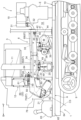
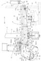
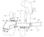
- FIG. FIG. FIG. 2 is a right side view showing the exhaust pipe and its surrounding structure.
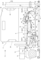
- FIG. 2 is a plan view showing the exhaust pipe and its surrounding structure.
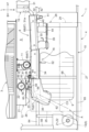
- FIG. 2 is a left side view showing the exhaust pipe and its surrounding structure.
- FIG. 4 is a rear view showing the exhaust pipe and its surrounding structure.
- FIG. FIG. FIG. FIG. 2 is a plan view showing the exhaust pipe and its surrounding structure, with a second exhaust pipe member and a third exhaust pipe member removed.
- FIG. 2 is a right side view showing the exhaust pipe and its surrounding structure with a second exhaust pipe member and a third exhaust pipe member removed.
- FIG. 2 is a diagram showing a control configuration of a combine harvester.
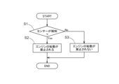
- FIG. 11 is a diagram illustrating a first control flow.
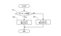
- FIG. 11 is a diagram illustrating a second control flow.
- FIG. 11 is a right side view of an exhaust pipe according to another embodiment.
- the direction of arrow F is the "front of the aircraft”
- the direction of arrow B is the “rear of the aircraft”
- the direction of arrow L is the “left side of the aircraft”
- the direction of arrow R is the “right side of the aircraft.”
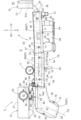
- Figures 1 and 2 show a combine harvester.
- the combine harvester is a head-feeding type.
- the combine harvester is equipped with a body 1, a harvesting section 2, a threshing device 3, a grain storage tank 4, a grain discharge device 5, a driver's cabin 6, a motor section 7, and an exhaust pipe 8.
- the machine body 1 is equipped with left and right crawler running devices 9 and a machine body frame 10.
- the machine body frame 10 is supported by the left and right crawler running devices 9.
- the reaping unit 2 reaps the planted culms.
- the reaping unit 2 is located at the front of the machine body 1.
- the reaping unit 2 is configured as a four-row reaping unit.
- the reaping unit 2 is not limited to a four-row reaping unit.
- the reaping unit 2 may be configured as a two-row, three-row, or five-row or more reaping unit.
- the threshing device 3 threshes the harvested stalks and separates the threshed grains into first-grain grains (single grains, etc.) and second-grain grains (grains with stalks, etc.).
- the threshing device 3 is equipped with a lifting device 11 and a second return device 12.
- the lifting device 11 transports the first-grain grains upward toward the grain storage tank 4.
- the second return device 12 returns the second-grain grains to the front of the threshing device 3.
- the second-grain grains returned to the front of the threshing device 3 by the second return device 12 are sorted again by the threshing device 3.
- the lifting device 11 and the second return device 12 are provided on the side of the threshing device 3 facing the grain storage tank 4 (the right side in this embodiment).
- the second return device 12 is provided behind the lifting device 11 on the right side of the threshing device 3.
- the grain storage tank 4 stores grains from the threshing device 3.
- the grain storage tank 4 is disposed adjacent to the threshing device 3 in the left-right direction of the machine body (in this embodiment, adjacent to the right of the threshing device 3).
- the grain storage tank 4 is configured to be swingable around a swing axis Z1 extending in the vertical direction between a storage position (position indicated by a solid line in FIG. 2) for storing grains from the threshing device 3, and an open position (position indicated by a two-dot chain line in FIG. 2) for opening the side of the threshing device 3 facing the grain storage tank 4 (in this embodiment, the right side).
- the grain storage tank 4 is configured to be able to change its state between a storage state for storing grains from the threshing device 3 and an open state for opening the side of the threshing device 3 facing the grain storage tank 4 (in this embodiment, the right side).
- the grain discharge device 5 discharges grains from the grain storage tank 4.
- the grain discharge device 5 is installed upright at the rear of the grain storage tank 4.
- the grain discharge device 5 is configured to be rotatable around a rotation axis Z2 that extends in the vertical direction and is the same axis as the swing axis Z1.
- the grain discharge device 5 includes a vertical grain conveying section 13 that conveys the grains in the grain storage tank 4 upward, and a horizontal grain conveying section 14 that conveys the grains in a horizontal direction from the vertical grain conveying section 13.
- the horizontal grain conveying section 14 is supported on the upper end of the vertical grain conveying section 13 so as to be able to swing up and down.
- the horizontal grain transport section 14 is configured to be foldable.
- the driver's cabin 6 is positioned offset to one of the left and right sides of the machine body 1 (the right side in this embodiment). In other words, the driver's cabin 6 is positioned in front of the grain storage tank 4.
- the driver's cabin 6 includes a driver's section 15 in which the driver sits, and a cabin section 16 that covers the driver's section 15.
- the driver's section 15 includes a driver's seat 17.
- the motive power unit 7 is provided below the driving unit 15. That is, the motive power unit 7 is provided in front of the grain storage tank 4.
- the motive power unit 7 includes an engine room 18, an engine E, and an exhaust purification device 19.
- the engine room 18 houses the engine E and the exhaust purification device 19.
- the engine room 18 is formed below the driving unit 15. That is, the engine room 18 is formed in front of the grain storage tank 4.
- the exhaust purification device 19 purifies the exhaust gas from the engine E.
- the exhaust purification device 19 purifies the exhaust gas from the engine E using a DPF (Diesel Particulate Filter).
- the lifting device 11 is equipped with a removable cleaning port cover 20 that covers the cleaning port (not shown). By removing the cleaning port cover 20, maintenance of the inside of the lifting device 11 can be performed through the cleaning port.
- the second reduction device 12 comprises a processing body 21 and a vertical conveying section 22.
- the processing body 21 threshes and processes the second grains.
- the processing body 21 comprises a removable cleaning port cover 23 that covers a cleaning port (not shown). By removing the cleaning port cover 23, maintenance of the inside of the processing body 21 can be performed through the cleaning port.
- the vertical conveying section 22 conveys the second grains upward after threshing by the processing body 21.
- the vertical conveying section 22 comprises a removable cleaning port cover 89 that covers a cleaning port (not shown). By removing the cleaning port cover 89, maintenance of the inside of the vertical conveying section 22 can be performed through the cleaning port.
- the grain storage tank 4 has a front wall 24, a rear wall 25, a left side wall 26, a right side wall 27, and a lower narrowing portion 28.
- the front wall 24 is made of a flat or approximately flat plate. That is, the front wall 24 is formed in a flat or approximately flat shape.
- the rear wall 25 is made of a flat or approximately flat plate. That is, the rear wall 25 is formed in a flat or approximately flat shape.
- the left side wall 26 is the side wall of the grain storage tank 4 facing the threshing device 3.
- the left side wall 26 is made of a flat or approximately flat plate. That is, the left side wall 26 is formed in a flat or approximately flat shape.
- the right side wall 27 is the side wall of the grain storage tank 4 on the opposite side to the threshing device 3.
- the right side wall 27 is made of a flat or approximately flat plate. That is, the right side wall 27 is formed in a flat or approximately flat shape.
- a front recess 29 that is recessed toward the inside of the grain storage tank 4 is formed in the corner formed by the front wall 24 and the left side wall 26.
- the front recess 29 is formed in a part of the corner formed by the front wall 24 and the left side wall 26. In other words, the corner formed by the front wall 24 and the left side wall 26 is partially recessed toward the inside of the grain storage tank 4.
- a rear recess 29 that is recessed toward the inside of the grain storage tank 4 is formed in the corner formed by the rear wall 25 and the left side wall 26.
- the rear recess 29 is formed in a part of the corner formed by the rear wall 25 and the left side wall 26. In other words, the corner formed by the rear wall 25 and the left side wall 26 is partially recessed toward the inside of the grain storage tank 4.
- the lower narrowing portion 28 is formed at the bottom of the grain storage tank 4.
- the lower narrowing portion 28 narrows downward when viewed from the front-to-rear direction of the machine body.
- a bottom screw 30 is provided at the bottom of the lower narrowing portion 28. The bottom screw 30 transports the grains in the grain storage tank 4 rearward toward the grain vertical transport section 13.
- the lower narrowing portion 28 has a bottom 28a.
- the bottom 28a is made of a flat plate having a flat or nearly flat shape. In other words, the bottom 28a is formed in a flat or nearly flat shape.
- the bottom 28a is inclined downward to the right.
- the inclination angle of the bottom 28a is indicated by ⁇ .
- the inclination angle ⁇ of the bottom 28a is the inclination angle with respect to the horizontal line.
- the inclination angle ⁇ of the bottom 28a is set to 40 degrees or approximately 40 degrees.
- the inclination angle ⁇ of the bottom 28a is set to the angle of repose of the grain. In other words, the bottom 28a is inclined at the angle of repose of the grain.
- the exhaust purification device 19 is disposed above the left side of the engine E.
- the exhaust purification device 19 is disposed in front of the space S between the threshing device 3 and the grain storage tank 4.
- the exhaust purification device 19 comprises the DPF (not shown), an exhaust purification case 31, and a tail pipe 32.
- the exhaust purification case 31 houses the DPF.
- the exhaust purification case 31 is composed of a member having a substantially cylindrical shape.
- the exhaust purification case 31 is formed with an exhaust section 31a.
- the exhaust section 31a discharges the exhaust gas from the engine E after purification processing by the DPF.
- the exhaust section 31a is provided at the lower rear part of the outer periphery of the exhaust purification case 31.
- the exhaust section 31a protrudes diagonally downward and to the right from the exhaust purification case 31.
- the upstream exhaust end of the tail pipe 32 is connected to the exhaust section 31a.
- the downstream exhaust end of the tail pipe 32 is connected to the exhaust pipe 8.
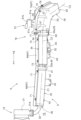
- the exhaust pipe 8 discharges the exhaust of the engine E. After being purified by the exhaust purification device 19, the exhaust pipe 8 discharges the exhaust of the engine E.
- the exhaust pipe 8 is disposed above the machine frame 10.
- the exhaust pipe 8 passes below the lower narrowing portion 28 between the threshing device 3 and the grain storage tank 4. Specifically, the exhaust pipe 8 passes below the bottom 28a.
- the exhaust pipe 8 extends parallel or approximately parallel to the bottom 28a.
- the exhaust pipe 8 overlaps with the grain storage tank 4 in plan view. Specifically, the exhaust pipe 8 overlaps with the lower narrowing portion 28 in plan view.
- the exhaust pipe 8 overlaps with the threshing device 3 and the grain storage tank 4 in side view. Specifically, the exhaust pipe 8 overlaps with the lower part of the threshing device 3 and the lower narrowing portion 28 in side view.
- the exhaust pipe 8 passes between the grain storage tank 4 and the lifting device 11. Specifically, the exhaust pipe 8 passes between the lower narrowing portion 28 and the lifting device 11 and the second reduction device 12.
- the exhaust pipe 8 and the exhaust purification device 19 are arranged at different positions in the left-right direction of the machine body. Specifically, the exhaust pipe 8 is located closer to the grain storage tank 4 (in this embodiment, on the right side) than the exhaust purification device 19 in the left-right direction of the machine body.
- the exhaust pipe 8 and the exhaust purification device 19 are arranged at different positions in the up-down direction. Specifically, the exhaust pipe 8 is arranged lower than the exhaust purification device 19.
- the exhaust pipe 8 is supported by a member other than the grain storage tank 4.
- the exhaust pipe 8 is supported by at least one of the machine frame 10 and the threshing device 3. In other words, the exhaust pipe 8 is not supported by the grain storage tank 4.
- a portion of the exhaust pipe 8 is configured to be detachable.
- the detachable portion of the exhaust pipe 8 includes the downstream exhaust portion of the exhaust pipe 8. In other words, at least a portion of the exhaust pipe 8 is configured to be detachable.
- the exhaust pipe 8 is divided into multiple (three in this embodiment) exhaust pipe members.
- the three exhaust pipe members include a first exhaust pipe member 33, a second exhaust pipe member 34, and a third exhaust pipe member 35.
- the first exhaust pipe member 33, the second exhaust pipe member 34, and the third exhaust pipe member 35 are arranged in this order from the exhaust upstream side.
- the exhaust pipe 8 can be applied to combine harvesters of different vehicle sizes.
- the first exhaust pipe member 33 is made of a cylindrical straight pipe.
- the first exhaust pipe member 33 is made of a double pipe. In Figs. 7 to 9, the center line of the first exhaust pipe member 33 is indicated by C1.
- the first exhaust pipe member 33 is inclined downward toward the rear in a side view.
- the first exhaust pipe member 33 is inclined so that the exhaust downstream side is located to the right in a plan view.
- the exhaust upstream end of the first exhaust pipe member 33 overlaps with the exhaust downstream end of the tail pipe 32 from the radial outside of the exhaust pipe 8.
- a first small diameter section 33a is formed at the exhaust downstream end of the first exhaust pipe member 33.
- the first small diameter section 33a is formed to have a smaller diameter than other parts of the first exhaust pipe member 33.
- a first outside air introduction section 36 that introduces outside air into the exhaust pipe 8 is formed at the exhaust upstream end of the first exhaust pipe member 33.
- the first outside air introduction section 36 is formed at the connection between the tail pipe 32 and the first exhaust pipe member 33.
- the first outside air introduction section 36 is formed between the outer periphery of the exhaust downstream end of the tail pipe 32 and the inner periphery of the exhaust upstream end of the first exhaust pipe member 33.
- the first outside air introduction section 36 faces the engine room 18.
- the first outside air introduction section 36 opens into the engine room 18.
- the first exhaust pipe member 33 is supported by the aircraft frame 10. Specifically, the first exhaust pipe member 33 is supported by the aircraft frame 10 via a stay 37, a stay 38, and a base 39. The first exhaust pipe member 33 is supported by the aircraft frame 10 via a stay 40 and a support 41. The first exhaust pipe member 33 has a front mounting portion 42 and a rear mounting portion 43.
- a gear case 44 that transmits power from the engine E to the bottom screw 30 is attached to the base 39.
- the stay 38 is attached to the base 39 and the gear case 44.
- the stay 37 is attached to the stay 38.
- the rear mounting part 43 is attached to the stay 37. Specifically, the rear mounting part 43 is attached to the right side of the stay 37 and is fixed by front and rear bolts 45.
- the pillar 41 is erected on the aircraft frame 10 behind the engine compartment 18.
- the stay 40 is attached to the front mounting part 42 and the pillar 41. Specifically, the stay 40 is secured to the front mounting part 42 by a bolt 46 while being pressed against the right side, and is secured to the pillar 41 by a bolt 46 while being pressed against the rear side.
- the second exhaust pipe member 34 is made of a cylindrical straight pipe (double pipe).
- the second exhaust pipe member 34 is made of a double pipe. In Figs. 7 to 9, the center line of the second exhaust pipe member 34 is indicated by C2.
- the second exhaust pipe member 34 is arranged horizontally or approximately horizontally.
- the second exhaust pipe member 34 extends linearly along the front-rear direction of the aircraft in a plan view.
- the second exhaust pipe member 34 is located to the side (in this embodiment, to the right) of the lifting device 11.
- the first exhaust pipe member 33 and the second exhaust pipe member 34 are arranged to overlap each other. Specifically, the exhaust upstream end of the second exhaust pipe member 34 overlaps the first small diameter portion 33a from the radial outside of the exhaust pipe 8.
- the exhaust downstream end of the second exhaust pipe member 34 is formed with a second small diameter portion 34a.
- the second small diameter portion 34a is formed to have a smaller diameter than other parts of the second exhaust pipe member 34.
- a second outside air inlet 47 that introduces outside air into the exhaust pipe 8 is formed at the exhaust upstream end of the second exhaust pipe member 34.
- the second outside air inlet 47 is formed at the connection between the first exhaust pipe member 33 and the second exhaust pipe member 34. Specifically, the second outside air inlet 47 is formed between the outer periphery of the first small diameter portion 33a and the inner periphery of the exhaust upstream end of the second exhaust pipe member 34.
- a heat insulating material 48 is attached to the outer periphery of the connection between the first exhaust pipe member 33 and the second exhaust pipe member 34. Specifically, the heat insulating material 48 is attached to the outer periphery of the exhaust downstream end of the first exhaust pipe member 33.
- the second exhaust pipe member 34 is supported by the threshing device 3. Specifically, the second exhaust pipe member 34 is supported by the grain lifting device 11.
- the second exhaust pipe member 34 has front and rear mounting parts 49.
- the grain lifting device 11 has a mounting part 50.
- the front and rear mounting parts 49 are fixed to the mounting part 50 by front and rear bolts 51. Specifically, the front and rear mounting parts 49 are fixed by the front and rear bolts 51 while being pressed against the mounting part 50 from the right side.
- the rear mounting part 49 is provided with a front handle 52, which will be described in detail later.
- the center line C1 of the first exhaust pipe member 33 and the center line C2 of the second exhaust pipe member 34 are misaligned with each other. Specifically, the center line C1 of the first exhaust pipe member 33 and the center line C2 of the second exhaust pipe member 34 are misaligned with each other in plan view and side view. In other words, the exhaust pipe 8 is bent at the connection between the first exhaust pipe member 33 and the second exhaust pipe member 34.
- the third exhaust pipe member 35 is formed of a rectangular tubular member.
- the third exhaust pipe member 35 is bent so that the exhaust downstream side is located to the right side in a plan view.
- the third exhaust pipe member 35 is inclined downward toward the rear in a side view. That is, the exhaust downstream end of the exhaust pipe 8 is inclined downward toward the rear in a side view.
- the third exhaust pipe member 35 is inclined along the lower narrowing portion 28 in a view in the longitudinal direction of the aircraft. That is, the exhaust downstream end of the exhaust pipe 8 is inclined along the lower narrowing portion 28 in a view in the longitudinal direction of the aircraft.
- the third exhaust pipe member 35 is located to the side of the second reduction device 12 (to the right in this embodiment).
- the second exhaust pipe member 34 and the third exhaust pipe member 35 are provided overlapping each other. Specifically, the exhaust upstream end of the third exhaust pipe member 35 overlaps the second small diameter portion 34a from the radial outside of the exhaust pipe 8.
- a heat insulating material 53 is attached to the outer periphery of the third exhaust pipe member 35. Specifically, the heat insulating material 53 is attached to only three of the four faces of the outer periphery of the third exhaust pipe member 35. In other words, the heat insulating material 53 is not attached to one face (face 35a shown in FIG. 7) of the outer periphery of the third exhaust pipe member 35.
- a third outside air inlet 54 that introduces outside air into the exhaust pipe 8 is formed at the exhaust upstream end of the third exhaust pipe member 35.
- the third outside air inlet 54 is formed at the connection between the second exhaust pipe member 34 and the third exhaust pipe member 35. Specifically, the third outside air inlet 54 is formed between the outer periphery of the second small diameter portion 34a and the inner periphery of the exhaust upstream end of the third exhaust pipe member 35.
- a heat insulating material 55 is attached to the outer periphery of the connection between the second exhaust pipe member 34 and the third exhaust pipe member 35. Specifically, the heat insulating material 55 is attached to the outer periphery of the exhaust downstream end of the second exhaust pipe member 34.
- the third exhaust pipe member 35 is supported by the threshing device 3. Specifically, the third exhaust pipe member 35 is supported by the second reduction device 12.
- a stay 56 is fixed to the third exhaust pipe member 35 by front and rear bolts 57.
- the stay 56 is fixed to the stay 58 by bolts 59.
- the stay 56 is fixed by the bolt 59 while being pressed against the stay 58 from the right side.
- the stay 58 is fixed to the cleaning port cover 23 by front and rear bolts 60.
- the stay 56 is provided with a rear handle 61, which will be described in detail later.
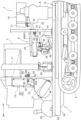
- an exhaust port 62 that opens to the outside is formed at the exhaust downstream end of the exhaust pipe 8.
- the exhaust port 62 is formed at the exhaust downstream end of the third exhaust pipe member 35.
- the exhaust downstream end of the third exhaust pipe member 35 is formed in a tapered shape with a cross section that becomes smaller toward the exhaust downstream side.
- the upper end of the threshing device 3 is indicated by P1
- the lower end of the machine frame 10 is indicated by P2.
- the lower end P2 of the machine frame 10 is the lower end of the lateral edge of the machine frame 10 (the side frame 65 described in detail later).
- the exhaust port 62 is located below the upper end P1 of the threshing device 3 and above the lower end P2 of the machine frame 10.
- the exhaust port 62 is located rearward of the vertical conveying section 22. In other words, the exhaust port 62 is located rearward of the grain lifting device 11.
- the exhaust port 62 is located forward of the part (grain vertical conveying section 13) that is erected rearward of the grain storage tank 4 in the grain discharge device 5. In this embodiment, the exhaust port 62 is located forward of the rear wall 25 of the grain storage tank 4.
- the exhaust port 62 opens downward. Specifically, the exhaust port 62 opens to the lower right when viewed in the longitudinal direction of the machine body, and opens to the lower rear when viewed from the side.
- the exhaust port 62 opens toward one of the pair of left and right crawler traveling devices 9 when viewed in the longitudinal direction of the machine body. In this embodiment, the exhaust port 62 opens toward the right crawler traveling device 9 of the pair of left and right crawler traveling devices 9 when viewed in the longitudinal direction of the machine body. In other words, the exhaust port 62 opens toward the crawler traveling device 9 on the grain storage tank 4 side of the pair of left and right crawler traveling devices 9 when viewed in the longitudinal direction of the machine body.
- a fuel tank 63 is disposed behind the threshing device 3. The exhaust port 62 opens to the opposite side of the fuel tank 63 in the transverse direction of the machine body (the right side in this embodiment).
- the machine frame 10 is configured in a frame shape.
- the machine frame 10 includes left and right main frames 64, left and right side frames 65, and multiple horizontal frames 66.
- the main frame 64 extends along the fore-and-aft direction of the machine.
- the left and right main frames 64 are disposed between the left and right crawler traveling devices 9.
- the side frames 65 extend along the fore-and-aft direction of the machine.
- the left side frame 65 is provided on the left edge of the machine frame 10.
- the right side frame 65 is provided on the right edge of the machine frame 10.
- the horizontal frames 66 extend along the left-and-right direction of the machine.
- the horizontal frames 66 are provided across the left and right side frames 65.
- the center extension line of the exhaust port 62 is indicated by C3.
- the center extension line C3 of the exhaust port 62 passes through frame A of the machine frame 10 and passes behind the right-side crawler traveling device 9. In other words, the center extension line C3 of the exhaust port 62 does not hit the machine frame 10 or the right-side crawler traveling device 9.
- Frame A of the machine frame 10 is located at the right rear corner of the machine frame 10.
- Frame A of the machine frame 10 is surrounded by front and rear horizontal frames 66 at the rear of the machine frame 10, a right side frame 65, and a right main frame 64.
- the area of frame A of the machine frame 10 is located above the rear end of the right crawler traveling device 9. In other words, the area of frame A of the machine frame 10 overlaps with the rear end of the right crawler traveling device 9 in a plan view.
- the first exhaust pipe member 33, the second exhaust pipe member 34, and the third exhaust pipe member 35 are covered by a cover 67.
- the cover 67 is disposed between the exhaust pipe 8 and the grain storage tank 4.
- the cover 67 covers the grain storage tank 4 side portions of the first exhaust pipe member 33, the second exhaust pipe member 34, and the third exhaust pipe member 35.
- the cover 67 is supported by the exhaust pipe 8. In other words, the cover 67 is not supported by the grain storage tank 4.
- the cover 67 includes a first cover member 68 that covers the first exhaust pipe member 33, a second cover member 69 that covers the second exhaust pipe member 34, and a third cover member 70 that covers the third exhaust pipe member 35.
- the first cover member 68 covers the portion of the first exhaust pipe member 33 on the grain storage tank 4 side.
- the upper surface of the first cover member 68 is inclined downward toward the grain storage tank 4 side (in this embodiment, downward to the right) in the left-right direction of the machine body.
- the first cover member 68 is attached to the first exhaust pipe member 33.
- the first exhaust pipe member 33 has three mounting portions 71.
- the first cover member 68 is fixed to each of the three mounting portions 71 with bolts 72.
- the front lower corners of the first cover member 68 are formed in a notched shape to avoid the stay 40.
- the second cover member 69 covers the portion of the second exhaust pipe member 34 on the grain storage tank 4 side.
- the upper surface of the second cover member 69 is inclined downward toward the grain storage tank 4 side (in this embodiment, downward to the right) in the left-right direction of the machine body.
- the second cover member 69 is attached to the second exhaust pipe member 34.
- the second exhaust pipe member 34 has three mounting portions 73.
- the second cover member 69 is fixed to each of the three mounting portions 73 by bolts 74.
- the rear end of the first cover member 68 and the front end of the second cover member 69 overlap each other. In this embodiment, the front end of the second cover member 69 overlaps the rear end of the first cover member 68 from the radial outside of the exhaust pipe 8.
- the third cover member 70 covers the portion of the third exhaust pipe member 35 on the grain storage tank 4 side.
- the upper surface of the third cover member 70 is inclined downward toward the grain storage tank 4 side (in this embodiment, downward to the right) in the left-right direction of the machine body.
- the third cover member 70 is attached to the third exhaust pipe member 35.
- the third exhaust pipe member 35 has two mounting parts 75.
- the third cover member 70 is fixed to each of the two mounting parts 75 with bolts 76.
- the rear end of the second cover member 69 and the front end of the third cover member 70 overlap each other. In this embodiment, the rear end of the second cover member 69 overlaps with the front end of the third cover member 70 from the radial outside of the exhaust pipe 8.
- the portion where the rear end of the second cover member 69 and the front end of the third cover member 70 overlap each other is fixed with a bolt 77.
- the second exhaust pipe member 34 and the third exhaust pipe member 35 form a unit 78.
- the exhaust downstream end of the second exhaust pipe member 34 and the exhaust upstream end of the third exhaust pipe member 35 are fixed with bolts 79, thereby forming a unit of the second exhaust pipe member 34 and the third exhaust pipe member 35.
- the second exhaust pipe member 34 has an attachment portion 80.
- the attachment portion 80 is provided at the exhaust downstream end of the second exhaust pipe member 34.
- the third exhaust pipe member 35 has an attachment portion 81.
- the attachment portion 81 is provided at the exhaust upstream end of the third exhaust pipe member 35.
- the attachment portions 80 and 81 are fixed with bolts 79. Specifically, the attachment portion 81 is fixed with the bolts 79 in a state where it is abutted against the attachment portion 80 from above.
- the second exhaust pipe member 34 and the second exhaust pipe member 34 are supported by the threshing device 3. That is, the unit 78 is supported by the threshing device 3. In other words, the unit 78 is supported by the same member.
- the second exhaust pipe member 34 and the third exhaust pipe member 35 can be removed by removing the front and rear bolts 51 and bolts 59.
- the second exhaust pipe member 34 and the third exhaust pipe member 35 are configured to be detachable as a single unit.
- the second exhaust pipe member 34, the third exhaust pipe member 35, the second cover member 69, and the third cover member 70 are configured to be detachable as a single unit.
- the second exhaust pipe member 34 and the third exhaust pipe member 35 are configured to be detachable. That is, at least one of the first exhaust pipe member 33, the second exhaust pipe member 34, and the third exhaust pipe member 35 is configured to be detachable. In other words, at least the third exhaust pipe member 35, which is located furthest downstream in the exhaust direction among the first exhaust pipe member 33, the second exhaust pipe member 34, and the third exhaust pipe member 35, is configured to be detachable.
- the second exhaust pipe member 34 is located to the side (in this embodiment, to the right) of the grain lifting device 11, and the third exhaust pipe member 35 is located to the side (in this embodiment, to the right) of the second reduction device 12.
- at least the portions of the exhaust pipe 8 located to the side (in this embodiment, to the right) of the grain lifting device 11 and the second reduction device 12 are configured to be removable.
- the second exhaust pipe member 34 and the second exhaust pipe member 34 are provided with a front handle 52 and a rear handle 61, respectively. That is, a plurality of (two in this embodiment) front handles 52 and rear handles 61 are provided on the detachable portion of the exhaust pipe 8 (the second exhaust pipe member 34 and the second exhaust pipe member 34).
- the front handles 52 and rear handles 61 are disposed at different positions in the fore-aft direction of the aircraft.
- the front handle 52 is disposed below the second exhaust pipe member 34.
- the rear handle 61 is disposed above the third exhaust pipe member 35. In other words, the front handle 52 and the rear handle 61 are disposed above and below, sandwiching the detachable portion of the exhaust pipe 8 (the second exhaust pipe member 34 and the second exhaust pipe member 34).
- the front handle 52 is disposed on the right side of the second exhaust pipe member 34.
- the rear handle 61 is disposed on the left side of the third exhaust pipe member 35.
- the front handle 52 and the rear handle 61 are disposed on the left and right sides of the detachable portion of the exhaust pipe 8 (the second exhaust pipe member 34 and the second exhaust pipe member 34).
- the front handle 52 is arranged along the left-right direction of the aircraft. Specifically, the front handle 52 extends to the right from the rear mounting portion 49.
- the rear handle 61 is arranged along the fore-and-aft direction of the aircraft. Specifically, the rear handle 61 is formed in a roughly C-shape that opens forward in a side view.
- the rear handle 61 has a first portion 61a extending along the up-down direction, a second portion 61b extending forward from the upper end of the first portion 61a, and a third portion 61c extending forward from the lower end of the first portion 61a.
- the third portion 61c is fixed to the stay 56.
- a stay 82 is fixed to the stay 58 by a bolt 83.
- An opening 82a is formed in the stay 82.
- the opening 82a is open in the fore-aft direction of the aircraft.
- the front end of the third portion 61c is inserted into the opening 82a from the rear.
- the exhaust pipe 8 is configured to be able to change its state between an emission state in which the exhaust of the engine E is discharged, and a non-emission state in which the exhaust of the engine E is not discharged.
- the emission state is a state in which the second exhaust pipe member 34 and the third exhaust pipe member 35 are attached.
- the non-emission state is a state in which the second exhaust pipe member 34 and the third exhaust pipe member 35 are removed.
- the change in state of the exhaust pipe 8 from the emission state to the non-emission state is detected by a sensor 84.
- the sensor 84 is attached to a stay 85.
- the stay 85 is fixed to the right side of the threshing device 3 by upper and lower bolts 86.
- the sensor 84 is supported on the right side of the threshing device 3 via the stay 85.
- a contact portion 56a that contacts the sensor 84 is formed on the front end of the stay 56. When the second exhaust pipe member 34 and the third exhaust pipe member 35 are attached, the contact portion 56a contacts the sensor 84 from the rear side.
- the second exhaust pipe member 34 and the third exhaust pipe member 35 can be removed by removing the front and rear bolts 51 and bolts 59. Specifically, the second exhaust pipe member 34 and the third exhaust pipe member 35 can be removed by the following procedure.
- the second exhaust pipe member 34 and the third exhaust pipe member 35 can be removed (see Figures 11 and 12).
- the exhaust pipe 8 can be changed from the exhaust state to the non-exhaust state.
- the lifting device 11 and the second reduction device 12 are opened by removing the second exhaust pipe member 34 and the third exhaust pipe member 35. This allows easy access to the lifting device 11 and the second reduction device 12 when performing maintenance on the lifting device 11 and the second reduction device 12 by changing the position of the grain storage tank 4 to the open position (see Figure 2).
- the combine may have a place (temporary storage place) for temporarily storing the removed second exhaust pipe member 34 and third exhaust pipe member 35.
- the temporary storage place may be provided, for example, in the vicinity of the grain storage tank 4.
- the temporary storage place may be provided with a hooking member (e.g., a rod, etc.) for hanging the removed second exhaust pipe member 34 and third exhaust pipe member 35.
- the front handle 52 and the rear handle 61 can be hung on the hooking member.
- the stay 56 moves away from the sensor 84.
- the sensor 84 detects that the exhaust pipe 8 has been changed from the exhaust state to the non-emission state by sliding the detachable portion of the exhaust pipe 8 (the second exhaust pipe member 34 and the third exhaust pipe member 35) to the side (the rear side in this embodiment) that moves away from the other portion of the exhaust pipe 8 (the first exhaust pipe member 33) in the fore-and-aft direction of the aircraft.
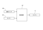
- FIG. 13 shows the control configuration of the combine harvester.
- the combine harvester is equipped with an engine E, a sensor 84, a control device 87, and a start switch 88.
- the control device 87 controls the engine E based on the detection results of the sensor 84.
- the start switch 88 commands the control device 87 to start the engine E.
- the control device 87 does not stop the engine E.
- the second exhaust pipe member 34 and the third exhaust pipe member 35 are configured to be detachable as a single unit.
- the second exhaust pipe member 34 and the third exhaust pipe member 35 may be configured to be swingable as a single unit.
- the front end of the second exhaust pipe member 34 is supported by a rotation mechanism 94 so as to be swingable up and down.
- a portion of the exhaust pipe 8 is configured to be able to swing.
- the portion of the exhaust pipe 8 that can swing includes the downstream exhaust portion of the exhaust pipe 8. In other words, at least a portion of the exhaust pipe 8 is configured to be able to swing.
- At least the portion of the exhaust pipe 8 located to the side (right) of the lifting device 11 and the second reduction device 12 (the second exhaust pipe member 34 and the third exhaust pipe member 35) is configured to be swingable.
- the first exhaust pipe member 33, the second exhaust pipe member 34, and the third exhaust pipe member 35, the second exhaust pipe member 34 and the third exhaust pipe member 35 are configured to be swingable. That is, at least one of the first exhaust pipe member 33, the second exhaust pipe member 34, and the third exhaust pipe member 35 is configured to be swingable.
- at least the third exhaust pipe member 35 located furthest downstream in the exhaust direction is configured to be swingable.
- front handles 52 and rear handles 61 are provided on the oscillating portion of the exhaust pipe 8 (the second exhaust pipe member 34 and the second exhaust pipe member 34).
- the front handles 52 and rear handles 61 are arranged vertically, sandwiching the oscillating portion of the exhaust pipe 8 (the second exhaust pipe member 34 and the second exhaust pipe member 34).
- the front handles 52 and rear handles 61 are arranged horizontally, sandwiching the oscillating portion of the exhaust pipe 8 (the second exhaust pipe member 34 and the second exhaust pipe member 34).
- the front and rear bolts 51 and 59 are removed, and the second exhaust pipe member 34 and the third exhaust pipe member 35 are slid toward the side (rear side) away from the first exhaust pipe member 33, so that the second exhaust pipe member 34 and the third exhaust pipe member 35 can be swung upward via the pivot mechanism 90. That is, the exhaust pipe 8 can be changed from the exhaust state to the non-emission state.
- the sensor 84 detects that the exhaust pipe 8 has been changed from the exhaust state to the non-emission state by the slidable portion of the exhaust pipe 8 (the second exhaust pipe member 34 and the third exhaust pipe member 35) being slid toward the side (rear side) away from the other portion of the exhaust pipe 8 (the first exhaust pipe member 33) in the fore-aft direction of the aircraft.
- the bottom 28a is inclined at the angle of repose of the grain.
- the bottom 28a may be inclined at an angle greater than the angle of repose of the grain.
- the bottom 28a may be inclined at an angle equal to or greater than the angle of repose of the grain.
- the corner formed by the front wall 24 and the left side wall 26 and the corner formed by the rear wall 25 and the left side wall 26 are each partially recessed into the inside of the grain storage tank 4.
- the corner formed by the front wall 24 and the left side wall 26 and the corner formed by the rear wall 25 and the left side wall 26 do not have to be partially recessed into the inside of the grain storage tank 4.
- the first exhaust pipe member 33 is supported by the machine frame 10, and the second exhaust pipe member 34 and the third exhaust pipe member 35 are supported by the threshing device 3.
- the present invention is not limited to the above embodiment.
- first exhaust pipe member 33, the second exhaust pipe member 34, and the third exhaust pipe member 35 may be supported by the machine frame 10. Also, the first exhaust pipe member 33, the second exhaust pipe member 34, and the third exhaust pipe member 35 may be supported by the threshing device 3.
- the exhaust purification device 19 is housed in the engine compartment 18.
- the exhaust purification device 19 may be provided outside the engine compartment 18. In this case, the exhaust purification device 19 is provided midway through the exhaust pipe 8.
- the first outside air introduction section 36 faces the engine room 18. However, the first outside air introduction section 36 does not have to face the engine room 18.
- the exhaust pipe 8 and the exhaust purification device 19 are disposed at different positions in the left-right direction of the aircraft.
- the exhaust pipe 8 and the exhaust purification device 19 may be disposed at the same position in the left-right direction of the aircraft.
- the exhaust pipe 8 and the exhaust purification device 19 are disposed at different positions in the vertical direction.
- the exhaust pipe 8 and the exhaust purification device 19 may be disposed at the same position in the vertical direction.
- the exhaust port 62 is located forward of the rear wall 25 of the grain storage tank 4.
- the exhaust port 62 may be located rearward of the rear wall 25 of the grain storage tank 4.
- the exhaust port 62 opens toward the crawler traveling device 9 on the grain storage tank 4 side of the pair of left and right crawler traveling devices 9 when viewed in the front-rear direction of the machine body. That is, the exhaust port 62 opens toward the right crawler traveling device 9 of the pair of left and right crawler traveling devices 9 when viewed in the front-rear direction of the machine body.
- the exhaust port 62 may also open toward the crawler traveling device 9 on the opposite side of the grain storage tank 4 of the pair of left and right crawler traveling devices 9 when viewed in the front-rear direction of the machine body. That is, the exhaust port 62 may also open toward the left crawler traveling device 9 of the pair of left and right crawler traveling devices 9 when viewed in the front-rear direction of the machine body.
- a portion of the exhaust pipe 8 is configured to be removable.
- the entire exhaust pipe 8 may be configured to be removable.
- the second exhaust pipe member 34 and the second exhaust pipe member 34 are provided with two “handles” (front handle 52 and rear handle 61).
- the second exhaust pipe member 34 and the second exhaust pipe member 34 may be provided with one or three or more "handles.”
- the exhaust pipe 8 is configured to be divided into three exhaust pipe members.
- the exhaust pipe 8 may be configured to be divided into two or four or more exhaust pipe members.
- the second exhaust pipe member 34 and the third exhaust pipe member 35 out of the first exhaust pipe member 33, the second exhaust pipe member 34, and the third exhaust pipe member 35 are configured to be detachable.
- the first exhaust pipe member 33, the second exhaust pipe member 34, and the third exhaust pipe member 35 may also be configured to be detachable.
- the combine harvester is provided with a cover 67.
- the combine harvester does not have to be provided with a cover 67.
- the present invention can be used not only for head-feeding combine harvesters, but also for whole-culm-feeding combine harvesters.
Landscapes
- Life Sciences & Earth Sciences (AREA)
- Environmental Sciences (AREA)
- Combines (AREA)
- Threshing Machine Elements (AREA)
Abstract
Cette moissonneuse-batteuse comprend un moteur, un cadre de corps de machine 10, un dispositif de battage 3 pour le battage de chaumes de grains récoltés, et un tuyau d'échappement 8 pour évacuer l'échappement du moteur. Un orifice d'échappement 62 ouvert vers l'extérieur est formé au niveau de la partie extrémité côté aval d'échappement du tuyau d'échappement 8. L'orifice d'échappement 62 est placé en dessous d'une extrémité supérieure P1 du dispositif de battage 3 et au-dessus d'une extrémité inférieure P2 du cadre de corps de machine 10.
Applications Claiming Priority (2)
| Application Number | Priority Date | Filing Date | Title |
|---|---|---|---|
| JP2023069581A JP2024155138A (ja) | 2023-04-20 | 2023-04-20 | コンバイン |
| JP2023-069581 | 2023-04-20 |
Publications (1)
| Publication Number | Publication Date |
|---|---|
| WO2024219009A1 true WO2024219009A1 (fr) | 2024-10-24 |
Family
ID=93152267
Family Applications (1)
| Application Number | Title | Priority Date | Filing Date |
|---|---|---|---|
| PCT/JP2023/044429 Ceased WO2024219009A1 (fr) | 2023-04-20 | 2023-12-12 | Moissonneuse-batteuse |
Country Status (2)
| Country | Link |
|---|---|
| JP (1) | JP2024155138A (fr) |
| WO (1) | WO2024219009A1 (fr) |
Citations (4)
| Publication number | Priority date | Publication date | Assignee | Title |
|---|---|---|---|---|
| JPH10164959A (ja) * | 1996-12-11 | 1998-06-23 | Mitsubishi Agricult Mach Co Ltd | コンバイン |
| JP2006034241A (ja) * | 2004-07-29 | 2006-02-09 | Iseki & Co Ltd | コンバイン |
| JP2009055806A (ja) * | 2007-08-30 | 2009-03-19 | Iseki & Co Ltd | 脱穀装置 |
| JP2018161084A (ja) * | 2017-03-24 | 2018-10-18 | 井関農機株式会社 | コンバイン |
-
2023
- 2023-04-20 JP JP2023069581A patent/JP2024155138A/ja active Pending
- 2023-12-12 WO PCT/JP2023/044429 patent/WO2024219009A1/fr not_active Ceased
Patent Citations (4)
| Publication number | Priority date | Publication date | Assignee | Title |
|---|---|---|---|---|
| JPH10164959A (ja) * | 1996-12-11 | 1998-06-23 | Mitsubishi Agricult Mach Co Ltd | コンバイン |
| JP2006034241A (ja) * | 2004-07-29 | 2006-02-09 | Iseki & Co Ltd | コンバイン |
| JP2009055806A (ja) * | 2007-08-30 | 2009-03-19 | Iseki & Co Ltd | 脱穀装置 |
| JP2018161084A (ja) * | 2017-03-24 | 2018-10-18 | 井関農機株式会社 | コンバイン |
Also Published As
| Publication number | Publication date |
|---|---|
| JP2024155138A (ja) | 2024-10-31 |
Similar Documents
| Publication | Publication Date | Title |
|---|---|---|
| CN106465604B (zh) | 联合收割机 | |
| JP6504866B2 (ja) | コンバイン | |
| CN105960933B (zh) | 联合收割机 | |
| JP2020000223A (ja) | コンバイン | |
| JP5843030B2 (ja) | コンバイン | |
| WO2024219009A1 (fr) | Moissonneuse-batteuse | |
| JP2025089490A (ja) | コンバイン | |
| CN106465605B (zh) | 联合收割机 | |
| JP6512995B2 (ja) | コンバイン | |
| JP6416025B2 (ja) | コンバイン | |
| WO2024219011A1 (fr) | Moissonneuse-batteuse | |
| JP6921887B2 (ja) | コンバイン | |
| JP7038579B2 (ja) | 収穫機 | |
| WO2024219008A1 (fr) | Moissonneuse-batteuse | |
| JP5880681B2 (ja) | コンバイン | |
| JP6960887B2 (ja) | コンバイン | |
| TWI727064B (zh) | 聯合收割機 | |
| JP7381441B2 (ja) | コンバイン | |
| JP7486897B2 (ja) | 作業車両 | |
| JP2012249528A (ja) | コンバイン | |
| JP7675881B2 (ja) | 作業機 | |
| JP2013158255A (ja) | 刈取収穫機 | |
| CN115279171B (zh) | 联合收割机及收割机 | |
| JP6887519B2 (ja) | コンバイン | |
| JP2007244309A (ja) | コンバイン |
Legal Events
| Date | Code | Title | Description |
|---|---|---|---|
| 121 | Ep: the epo has been informed by wipo that ep was designated in this application |
Ref document number: 23934149 Country of ref document: EP Kind code of ref document: A1 |
|
| NENP | Non-entry into the national phase |
Ref country code: DE |