WO2024219214A1 - Stratifié et procédé de fabrication de verre de lunettes - Google Patents
Stratifié et procédé de fabrication de verre de lunettes Download PDFInfo
- Publication number
- WO2024219214A1 WO2024219214A1 PCT/JP2024/013575 JP2024013575W WO2024219214A1 WO 2024219214 A1 WO2024219214 A1 WO 2024219214A1 JP 2024013575 W JP2024013575 W JP 2024013575W WO 2024219214 A1 WO2024219214 A1 WO 2024219214A1
- Authority
- WO
- WIPO (PCT)
- Prior art keywords
- laminate
- layer
- metal layer
- water
- lens substrate
- Prior art date
- Legal status (The legal status is an assumption and is not a legal conclusion. Google has not performed a legal analysis and makes no representation as to the accuracy of the status listed.)
- Ceased
Links
Images
Classifications
-
- G—PHYSICS
- G02—OPTICS
- G02B—OPTICAL ELEMENTS, SYSTEMS OR APPARATUS
- G02B1/00—Optical elements characterised by the material of which they are made; Optical coatings for optical elements
- G02B1/10—Optical coatings produced by application to, or surface treatment of, optical elements
- G02B1/11—Anti-reflection coatings
-
- G—PHYSICS
- G02—OPTICS
- G02B—OPTICAL ELEMENTS, SYSTEMS OR APPARATUS
- G02B1/00—Optical elements characterised by the material of which they are made; Optical coatings for optical elements
- G02B1/10—Optical coatings produced by application to, or surface treatment of, optical elements
- G02B1/14—Protective coatings, e.g. hard coatings
-
- G—PHYSICS
- G02—OPTICS
- G02B—OPTICAL ELEMENTS, SYSTEMS OR APPARATUS
- G02B1/00—Optical elements characterised by the material of which they are made; Optical coatings for optical elements
- G02B1/10—Optical coatings produced by application to, or surface treatment of, optical elements
- G02B1/18—Coatings for keeping optical surfaces clean, e.g. hydrophobic or photo-catalytic films
-
- G—PHYSICS
- G02—OPTICS
- G02C—SPECTACLES; SUNGLASSES OR GOGGLES INSOFAR AS THEY HAVE THE SAME FEATURES AS SPECTACLES; CONTACT LENSES
- G02C13/00—Assembling; Repairing; Cleaning
-
- G—PHYSICS
- G02—OPTICS
- G02C—SPECTACLES; SUNGLASSES OR GOGGLES INSOFAR AS THEY HAVE THE SAME FEATURES AS SPECTACLES; CONTACT LENSES
- G02C7/00—Optical parts
-
- G—PHYSICS
- G02—OPTICS
- G02C—SPECTACLES; SUNGLASSES OR GOGGLES INSOFAR AS THEY HAVE THE SAME FEATURES AS SPECTACLES; CONTACT LENSES
- G02C7/00—Optical parts
- G02C7/10—Filters, e.g. for facilitating adaptation of the eyes to the dark; Sunglasses
Definitions
- This disclosure relates to a method for manufacturing a laminate and an eyeglass lens.
- the present disclosure relates to a laminate having a spectacle lens substrate, a water-repellent layer, and a metal layer in this order, wherein the metal layer contains at least one selected from the group consisting of aluminum, zinc, copper, and nickel (embodiment 1).
- the laminate of the present disclosure can be ground with small axial and horizontal deviations.
- the present disclosure also relates to a method for manufacturing a spectacle lens, comprising step 1 of pressing a fixing member against the metal layer of a laminate having a spectacle lens substrate, a water-repellent layer, and a metal layer in this order to fix the laminate and grinding the periphery of the laminate, and step 2 of removing the metal layer in the ground laminate, the metal layer including at least one selected from the group consisting of aluminum, zinc, copper, and nickel (embodiment 2).
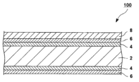
- FIG. 2 is a schematic cross-sectional view of a laminate.
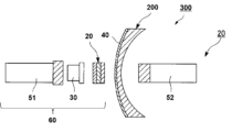
- FIG. 2 is a schematic view of a portion of a grinding apparatus.
- the laminate is preferably used to be ground by pressing a fixing member against the metal layer in the laminate to fix the laminate, in other words, it is preferably used in step 1 of the manufacturing method of a spectacle lens described later.
- 1 is a cross-sectional schematic diagram of a laminate 100.
- the laminate 100 has an antireflection layer 4 on a spectacle lens substrate 2, a water-repellent layer 6 on the antireflection layer 4, and a metal layer 8 on the water-repellent layer 6.
- the laminate 100 does not necessarily have to have the antireflection layer 4.
- the laminate 100 may further have a primer layer described later and/or a hard coat layer described later.
- the laminate may have a water-repellent layer and a metal layer on only one surface of the eyeglass lens substrate, or may have a water-repellent layer and a metal layer on both surfaces of the eyeglass lens substrate.
- the luminous transmittance of the laminate is preferably less than 100%, more preferably 90% or less, and even more preferably 88% or less.
- the lower limit is preferably 0% or more, more preferably 10% or more, and even more preferably 20% or more.
- the luminous transmittance can be adjusted, for example, by adjusting the thickness of each layer (for example, a metal layer) in the laminate.
- the luminous transmittance is the average value of the transmittance in the wavelength range of 380 to 780 nm, and can be measured using a spectrometer.
- the spectacle lens substrate examples include spectacle lens substrates made of organic or inorganic materials, and spectacle lens substrates made of organic materials (such as plastic lens substrates) are preferred.
- spectacle lens substrates include finished lenses in which both the convex and concave surfaces are optically finished and molded to match a desired dioptric power, semi-finished lenses in which only the convex surface is finished as an optical surface (e.g., a spherical surface, a rotationally symmetric aspheric surface, a progressive surface, etc.), and semi-finished lenses in which the concave surface is processed and polished to match the wearer's prescription.
- organic materials include acrylic resins, methacrylic resins, thiourethane resins, allyl resins, episulfide resins, polycarbonate resins, polyurethane resins, polyester resins, polystyrene resins, polyethersulfone resins, poly-4-methylpentene-1 resins, diethylene glycol bisallyl carbonate resins (CR-39), and polyvinyl chloride resins.
- the thickness of the spectacle lens substrate is preferably 1 to 30 mm from the viewpoint of ease of handling.
- the spectacle lens substrate may be opaque or colored so long as it has light-transmitting properties.
- the laminate has a water-repellent layer on a spectacle lens substrate.
- the water-repellent layer preferably contains at least one selected from the group consisting of organosilicon compounds, their hydrolysates, and their hydrolyzed condensates.
- the hydrolyzate of an organosilicon compound means a compound that is generated by hydrolyzing the hydrolyzable group in an organosilicon compound that has a hydrolyzable group.
- the hydrolyzate of an organosilicon compound may be a complete hydrolyzate in which all the hydrolyzable groups in the organosilicon compound are hydrolyzed, a partial hydrolyzate in which some of the hydrolyzable groups are decomposed, or a mixture thereof.
- the hydrolysis condensate of an organosilicon compound means a compound that is produced by condensing the hydrolysis product of an organosilicon compound having a hydrolyzable group.
- the hydrolysis condensate of an organosilicon compound may be a complete hydrolysis condensate in which all the hydrolyzed groups in the hydrolysis product are condensed, a partial hydrolysis condensate in which only a part of the hydrolysis groups are condensed, or a mixture thereof.
- Organosilicon compounds include, for example, silane compounds, silazane compounds, silanol compounds, siloxane compounds, silicate compounds, and silyl ester compounds, with silane compounds being preferred.
- hydrolyzable groups examples include alkoxy groups, halogen atoms, cyano groups, acetoxy groups, and isocyanate groups.
- the organosilicon compound preferably has a fluorine atom-containing group.
- fluorine atom-containing group include a group having a perfluorocarbon structure and a group having a perfluoropolyether structure.
- organosilicon compound examples include those described in WO 2020/039795, U.S. Pat. No. 4,410,563, EP 0,203,730, EP 749,021, EP 844,265, and EP 933,377.
- the thickness of the water-repellent layer is preferably 1 to 1000 nm.
- the laminate has a metal layer on a water-repellent layer.
- the laminate preferably has a metal layer adjacent to the water-repellent layer.
- the metal layer has excellent adhesion to the fixing member in step 1 described below, and therefore, when the laminate is ground, the metal layer is easily ground into a desired shape with little axial deviation, etc.
- the metal layer is a layer that is removed after grinding.
- the metal layer contains at least one metal selected from the group consisting of aluminum, zinc, copper and nickel (hereinafter also referred to as the "specific metal"), and preferably contains aluminum.
- the specific metal may be either a pure metal or an alloy, with a pure metal being preferred. As long as the metal layer contains the specific metal, it may contain other metals, such as known metals.
- the content of the specific metal is preferably 50% by mass or more, more preferably 80% by mass or more, even more preferably 95% by mass or more, and particularly preferably 99% by mass or more, based on the total mass of the metal layer.
- the upper limit is preferably 100% by mass or less.
- the thickness of the metal layer is preferably 0.1 to 200.0 nm, more preferably 1.0 to 100.0 nm, and even more preferably 5.0 to 80.0 nm.
- the laminate may have other layers in addition to the above layers.
- the other layers include a primer layer, a hard coat layer, an anti-reflection layer, and an intermediate layer.
- the laminate preferably has the intermediate layer on the opposite side of the water-repellent layer to the metal layer.
- the laminate further has a primer layer, a hard coat layer and an antireflection layer, in this order from the eyeglass lens substrate side, between the eyeglass lens substrate and the water-repellent layer.
- the primer layer is a layer that improves the adhesion of the hard coat layer to the eyeglass lens substrate.
- the primer layer preferably contains a resin, and more preferably contains a urethane-based resin, an epoxy-based resin, a phenol-based resin, a polyimide-based resin, a polyester-based resin, a bismaleimide-based resin, or a polyolefin-based resin.
- the thickness of the primer layer is preferably 0.3 to 2 ⁇ m.
- the hard coat layer is a layer disposed on the spectacle lens substrate, and is a layer that imparts scratch resistance to the spectacle lens substrate.
- Examples of the hard coat layer include an organic hard coat layer, an inorganic hard coat layer, and an organic-inorganic hybrid hard coat layer.
- the thickness of the hard coat layer is preferably from 1.0 to 20.0 ⁇ m, and more preferably from 1.5 to 15.0 ⁇ m.
- the composition for forming a hard coat layer preferably contains at least one selected from the group consisting of an inorganic compound, a polymerization initiator, and an organic solvent.
- Inorganic compounds include, for example, inorganic oxides and silsesquioxanes.
- the inorganic oxide is preferably a metal oxide particle.
- the metal oxide particles include oxide particles of at least one metal selected from the group consisting of Ti, Zr, Si, Al, Sn, Sb, Ta, Ce, La, Fe, Zn, W, and In, and composite metal oxide particles thereof.
- Composite metal oxide particles are oxide particles containing two or more metals (metal atoms).
- the inorganic oxide particles preferably contain at least one selected from the group consisting of SiO2 (silicon oxide), Al2O3 (aluminum oxide), SnO2 (tin oxide), ZrO2 (zirconium oxide) and TiO2 (titanium oxide), and more preferably contain at least one selected from the group consisting of SiO2 and ZrO2 .
- Silsesquioxanes are silane compounds obtained by hydrolysis of trifunctional silane compounds such as alkoxysilanes, chlorosilanes, and silanols.
- the antireflection layer may have either a single-layer structure or a multi-layer structure.
- the antireflection layer is preferably an inorganic antireflection layer, which means an antireflection layer made of an inorganic compound.
- the multi-layered antireflection layer may have a structure in which high refractive index layers and low refractive index layers are alternately laminated.
- the high refractive index layer preferably comprises an oxide of titanium, zirconium, aluminum, niobium, tantalum, or lanthanum.
- the low refractive index layer preferably contains a silica compound.
- the thickness of the antireflection layer is preferably from 0.2 to 3.0 ⁇ m, and more preferably from 0.3 to 2.0 ⁇ m.
- the laminate can be produced, for example, by a known production method.
- the method for producing the laminate is preferably a method for producing the laminate including a step of forming a water-repellent layer on a spectacle lens substrate, and a step of forming a metal layer on the water-repellent layer.
- the step of forming the water-repellent layer is preferably a step of applying a composition for forming a water-repellent layer onto a spectacle lens substrate and curing the composition.
- a composition for forming a water-repellent layer examples include dip coating, roll coating, bar coating, spin coating, spray coating, die coating, and gravure coating.
- the curing method may be, for example, a drying method, and the drying may or may not involve heating.
- the composition for forming the water-repellent layer is a composition containing the various components that the water-repellent layer can contain, and preferably further contains an organic solvent.
- Examples of the process for forming the metal layer include dry film formation methods such as physical vapor deposition and chemical vapor deposition, and wet film formation methods such as coating, with physical vapor deposition being preferred.
- Examples of physical vapor deposition include deposition methods such as thermal deposition and electron beam deposition, and sputtering, with thermal deposition being preferred since it can reduce damage to the laminate (e.g., the water-repellent layer, etc.).
- the dry film-forming method and the wet film-forming method may be carried out under normal pressure, reduced pressure, or high pressure, and are preferably carried out under reduced pressure.
- the method for producing the laminate includes the steps of forming a primer layer on a spectacle lens substrate, forming a hard coat layer on the primer layer, forming an anti-reflection layer on the hard coat layer, forming a water-repellent layer on the anti-reflection layer, and forming a metal layer on the water-repellent layer.
- the step of forming the water-repellent layer and the step of forming the metal layer are as described above.
- the step of forming the primer layer is preferably a method of applying a primer layer-forming composition onto the spectacle lens substrate.
- the step of forming the primer layer may include a drying step. The drying may be performed with or without heating.
- the step of forming the hard coat layer is preferably a method of applying a composition for forming a hard coat layer onto the primer layer and curing the composition.
- the coating method of the composition for forming a hard coat layer can be, for example, the coating method of the composition for forming a water-repellent layer described above.
- the spectacle lens substrate having a primer layer is immersed in the composition for forming a hard coat layer, and then the spectacle lens substrate having the primer layer is pulled up and dried, so that a coating film derived from the composition for forming a hard coat layer can be formed on the primer layer of the spectacle lens substrate.
- the curing method includes, for example, a heat treatment and an exposure treatment.
- the heat treatment conditions and light irradiation treatment conditions can be appropriately adjusted depending on the various components contained in the composition for forming a hard coat layer.
- the type of light used for the light irradiation may be, for example, ultraviolet light or visible light, and the light source may be, for example, a high-pressure mercury lamp.
- the integrated light quantity during light irradiation is preferably from 100 to 10,000 mJ/cm 2 , and more preferably from 100 to 5,000 mJ/cm 2 , from the viewpoints of productivity and curability of the coating film.
- the process for forming the anti-reflective layer can be a dry process such as vacuum deposition, sputtering, ion plating, ion beam assisted deposition, or CVD.
- the method for manufacturing a spectacle lens includes step 1 of pressing a fixing member against a metal layer of a laminate having a spectacle lens substrate, a water-repellent layer, and a metal layer in this order to fix the laminate, and grinding the periphery of the laminate, and step 2 of removing the metal layer in the ground laminate, wherein the metal layer contains a specific metal.
- the laminate in the method for manufacturing eyeglass lenses is the same as the laminate described above, and the preferred embodiment is also the same.
- Step 1 is a step of processing the laminate into a predetermined shape by grinding the periphery of the laminate, which is a so-called bead grinding step. Grinding can be performed using a known grinding device.
- FIG. 2 is a schematic diagram of the grinding device 300 in step 1, and step 1 will be described in detail with reference to FIG.
- the laminate 200 is placed between the fixing member 60 and the lens processing shaft 52 so that the fixing member 60 is in contact with the metal layer 40 of the laminate 200, and the fixing member 60 is pressed against the laminate 200 to fix it. That is, the laminate 200 is pressed and fixed by the fixing member 60 and the lens processing shaft 52. Also, in Fig.
- the fixing member 60 has the lens processing shaft 51, the lens lock cap 30 fixed to the tip of the lens processing shaft 51, and the adhesive tape 20 attached to the surface of the lens lock cap 30, and the surface of the adhesive tape 20 opposite to the surface of the lens lock cap 30 is in contact with the metal layer of the laminate 200, but is not limited to such an embodiment.
- An example of the grinding device 300 is LE-9000X (manufactured by NIDEK).
- An example of the adhesive tape 20 is LEAPIII (manufactured by 3M).
- the grinding method in step 1 may be, for example, the beveling process described in JP-A-2007-156226, JP-A-2003-141607, and JP-A-2007-505937.
- Step 2 is a step of removing the metal layer in the ground laminate.
- Methods for removing the metal layer include, for example, a method for removing the metal layer by tape peeling, a method for removing the metal layer using a release agent, a dry wiping method, and a combination of these.
- the method for removing the metal layer by tape peeling or the method for removing the metal layer using a release agent are preferred.
- An example of the dry wiping method is to rub the metal layer with a wipe.
- An example of the tape peeling method is a method in which a metal layer is peeled off using a known tape.
- the release agent include organic solvents such as alcohol solvents, water, and mixtures thereof, and alcohol solvents are preferred.
- the release agent may contain an anionic surfactant, a cationic surfactant, and/or an amphoteric surfactant.
- the stripping agent may be acidic, neutral or alkaline.
- the laminates used in Examples 1 to 3 were prepared in the following manner.
- ECC product name, manufactured by Nikon-Essilor
- the eyeglass lens has an eyeglass lens substrate (diameter 70 mm, ⁇ 10.00D) with a refractive index of 1.60, a primer layer, a hard coat layer, an anti-reflection layer, and a water-repellent layer in this order.
- an aluminum layer having a purity of 99% by mass or more was formed on the water-repellent layer of the eyeglass lens 1 by thermal evaporation using a physical vapor deposition apparatus (BC-P: manufactured by Synchron, or 1200-DLX2: manufactured by Satisloh) while adjusting the thickness so as to obtain the luminous transmittance shown in the table below, thereby obtaining a laminate 1.
- BC-P physical vapor deposition apparatus
- 1200-DLX2 manufactured by Satisloh
- Laminates 2 and 3 were formed by adjusting the thickness of the aluminum layer with a purity of 99% by mass or more on the water-repellent layer of eyeglass lens 1, with reference to the procedure for laminate 1 described above, so as to achieve the luminous transmittance shown in the table below.
- the eyeglass lens used in Comparative Example 1 was used for evaluation as is, without forming an aluminum layer on eyeglass lens 1.
- Luminous transmittance of laminate The luminous transmittance of the laminate was measured using a spectrometer (LED spectrometer, manufactured by Fuji Kohden Kogyo Co., Ltd.).
- Step 1 was carried out using the obtained laminate or eyeglass lens, and the axial deviation and horizontal deviation after grinding were evaluated.
- the optical center of the laminate was identified using a lens meter (LM-1200, manufactured by Nidek Co., Ltd.), and a total of three points, including the optical center, were marked on the surface of the metal layer of the laminate so as to be equidistant on any line passing through the optical center on the surface of the metal layer.
- LM-1200 manufactured by Nidek Co., Ltd.
- a double-sided tape (LEAP III, manufactured by 3M Co., Ltd.) was attached to the laminate using a lens blocker (CE-1, manufactured by Nidek Co., Ltd.) with a point shifted from the optical center by the amount of eccentricity (a point shifted from the optical center by 5 mm on a line passing through the above three points), and a lens lock cap was further attached on top of the double-sided tape.
- the lens lock cap with the laminate attached was fitted to one of the lens processing shafts of the edging machine, and then the laminate was sandwiched and fixed between the lens lock cap and the other processing shaft, and the edging process was performed with the eccentricity set to zero on the edging machine side.
- the equipment and tools used for the edging process are listed below.
- the edging process was also performed on the eyeglass lenses using the same procedure as for the laminate.
- ⁇ Beveling machine LE-9000X (manufactured by NIDEK), chuck pressure value: 50 kg Lens shape: Nikon Classico, product number 9018 (approximately octagonal shape, 48 mm wide, 30 mm tall) - Lens lock cap: Smallest size cap (manufactured by NIDEK)
- the metal layer of the laminate ground in the evaluation of the axial deviation and the horizontal deviation was removed using tape stripping or ethanol.
- Nichiban 405 cellophane tape (width 18 mm, length 10 mm) was applied to the metal layer and the tape was peeled off three times. After this, the metal layer remaining on the eyeglass lens was visually inspected and it was found that the metal layer was almost completely removed in all examples.
- the metal layer was rubbed several times with a wipe soaked in ethanol, and the metal layer was completely removed in all Examples, and the metal layer was removed more cleanly than by the tape peeling method described above.
- the thickness of the metal layer was measured using a quartz crystal film thickness gauge to determine the thickness of the metal layer in each laminate before grinding.
- the numerical values for axial deviation and horizontal deviation indicate the absolute value of the amount of deviation.
Landscapes
- Physics & Mathematics (AREA)
- General Physics & Mathematics (AREA)
- Optics & Photonics (AREA)
- Health & Medical Sciences (AREA)
- Ophthalmology & Optometry (AREA)
- General Health & Medical Sciences (AREA)
- Chemical & Material Sciences (AREA)
- Chemical Kinetics & Catalysis (AREA)
- Surface Treatment Of Optical Elements (AREA)
Abstract
La présente invention aborde le problème de la fourniture d'un stratifié qui peut être poli avec de petits écarts axiaux et horizontaux. Ce stratifié comporte un substrat de verre de lunettes, une couche hydrofuge et une couche métallique dans cet ordre. La couche métallique contient au moins un élément choisi dans le groupe constitué par l'aluminium, le zinc, le cuivre et le nickel.
Applications Claiming Priority (2)
| Application Number | Priority Date | Filing Date | Title |
|---|---|---|---|
| JP2023067210 | 2023-04-17 | ||
| JP2023-067210 | 2023-04-17 |
Publications (1)
| Publication Number | Publication Date |
|---|---|
| WO2024219214A1 true WO2024219214A1 (fr) | 2024-10-24 |
Family
ID=93152790
Family Applications (1)
| Application Number | Title | Priority Date | Filing Date |
|---|---|---|---|
| PCT/JP2024/013575 Ceased WO2024219214A1 (fr) | 2023-04-17 | 2024-04-02 | Stratifié et procédé de fabrication de verre de lunettes |
Country Status (1)
| Country | Link |
|---|---|
| WO (1) | WO2024219214A1 (fr) |
Citations (7)
| Publication number | Priority date | Publication date | Assignee | Title |
|---|---|---|---|---|
| JP2000006297A (ja) * | 1998-06-18 | 2000-01-11 | Dainippon Printing Co Ltd | ガスバリア性フィルムとその製造方法およびガスバリア性フィルムを用いた積層材 |
| JP2005505427A (ja) * | 2001-05-17 | 2005-02-24 | エシロール アテルナジオナール カンパニー ジェネラーレ デ オプティック | トリミングに適したガラスの作製方法、それにより得られるガラスおよび該ガラスのトリミング方法 |
| JP2007156226A (ja) * | 2005-12-07 | 2007-06-21 | Seiko Epson Corp | 粘着テープ及び眼鏡レンズの玉型加工方法 |
| JP2010508541A (ja) * | 2006-10-31 | 2010-03-18 | エシロール アテルナジオナール カンパニー ジェネラーレ デ オプティック | 防汚膜を有する光学物品 |
| JP2013503456A (ja) * | 2009-08-31 | 2013-01-31 | ポーラス パワー テクノロジーズ,エルエルシー | 積層アセンブリを用いる電池の製造 |
| JP2013254161A (ja) * | 2012-06-08 | 2013-12-19 | Nikon-Essilor Co Ltd | 眼鏡用レンズ及びその加工方法 |
| WO2022097751A1 (fr) * | 2020-11-09 | 2022-05-12 | ホヤ レンズ タイランド リミテッド | Verre de lunettes et lunettes |
-
2024
- 2024-04-02 WO PCT/JP2024/013575 patent/WO2024219214A1/fr not_active Ceased
Patent Citations (7)
| Publication number | Priority date | Publication date | Assignee | Title |
|---|---|---|---|---|
| JP2000006297A (ja) * | 1998-06-18 | 2000-01-11 | Dainippon Printing Co Ltd | ガスバリア性フィルムとその製造方法およびガスバリア性フィルムを用いた積層材 |
| JP2005505427A (ja) * | 2001-05-17 | 2005-02-24 | エシロール アテルナジオナール カンパニー ジェネラーレ デ オプティック | トリミングに適したガラスの作製方法、それにより得られるガラスおよび該ガラスのトリミング方法 |
| JP2007156226A (ja) * | 2005-12-07 | 2007-06-21 | Seiko Epson Corp | 粘着テープ及び眼鏡レンズの玉型加工方法 |
| JP2010508541A (ja) * | 2006-10-31 | 2010-03-18 | エシロール アテルナジオナール カンパニー ジェネラーレ デ オプティック | 防汚膜を有する光学物品 |
| JP2013503456A (ja) * | 2009-08-31 | 2013-01-31 | ポーラス パワー テクノロジーズ,エルエルシー | 積層アセンブリを用いる電池の製造 |
| JP2013254161A (ja) * | 2012-06-08 | 2013-12-19 | Nikon-Essilor Co Ltd | 眼鏡用レンズ及びその加工方法 |
| WO2022097751A1 (fr) * | 2020-11-09 | 2022-05-12 | ホヤ レンズ タイランド リミテッド | Verre de lunettes et lunettes |
Similar Documents
| Publication | Publication Date | Title |
|---|---|---|
| EP2718750B1 (fr) | Procédé permettant d'obtenir des articles optiques offrant des propriétés de résistance à l'abrasion supérieures, et articles dotés d'un revêtement préparés selon un tel procédé | |
| JP7210285B2 (ja) | ハードコート層形成用組成物、眼鏡レンズ | |
| CN105556346B (zh) | 具有梯度光致变色性的光学物品 | |
| CN104884997B (zh) | 用于生产具有改进的防污特性的光学物品的方法 | |
| JP2014145955A (ja) | 光学物品およびその製造方法 | |
| JP2020187188A (ja) | 眼鏡レンズ | |
| JP2016509250A (ja) | 疎水二重層と一時金属フッ化物層とを含む縁取り可能な眼用レンズ | |
| CN106574987A (zh) | 包括保护性可去除的膜的光学镜片 | |
| US10732324B2 (en) | Method for laminating an interference coating comprising an organic/inorganic layer, and item thus obtained | |
| JP7519434B2 (ja) | 光学部材 | |
| WO2024219214A1 (fr) | Stratifié et procédé de fabrication de verre de lunettes | |
| CN104718466A (zh) | 抗反射透镜和制造所述抗反射透镜的方法 | |
| WO2025142483A1 (fr) | Stratifié et procédé de fabrication de lentille de lunettes | |
| TWI918342B (zh) | 積層體、眼鏡透鏡之製造方法 | |
| EP3164368B1 (fr) | Lentille ophtalmique ayant des proprietes antisalissure differenciees sur ses deux faces et procedes de fabrication | |
| JP2005234311A (ja) | 光学素子および光学素子の製造方法 | |
| JPH095679A (ja) | 眼鏡用プラスチックレンズ | |
| WO2025070120A1 (fr) | Verre de lunettes | |
| WO2025070123A1 (fr) | Verre de lunettes | |
| WO2024116961A1 (fr) | Procédé de fabrication d'article optique | |
| WO2025229952A1 (fr) | Verre de lunettes | |
| WO2024142935A1 (fr) | Procédé de production de verre de lunettes | |
| WO2025258437A1 (fr) | Procédé d'évaluation de verres de lunettes | |
| WO2025004987A1 (fr) | Procédé de production de lentille |
Legal Events
| Date | Code | Title | Description |
|---|---|---|---|
| 121 | Ep: the epo has been informed by wipo that ep was designated in this application |
Ref document number: 24792490 Country of ref document: EP Kind code of ref document: A1 |
|
| NENP | Non-entry into the national phase |
Ref country code: DE |
|
| 122 | Ep: pct application non-entry in european phase |
Ref document number: 24792490 Country of ref document: EP Kind code of ref document: A1 |