WO2024224732A1 - 台車 - Google Patents
台車 Download PDFInfo
- Publication number
- WO2024224732A1 WO2024224732A1 PCT/JP2024/003231 JP2024003231W WO2024224732A1 WO 2024224732 A1 WO2024224732 A1 WO 2024224732A1 JP 2024003231 W JP2024003231 W JP 2024003231W WO 2024224732 A1 WO2024224732 A1 WO 2024224732A1
- Authority
- WO
- WIPO (PCT)
- Prior art keywords
- axle
- motor
- bogie frame
- bogie
- motor bracket
- Prior art date
- Legal status (The legal status is an assumption and is not a legal conclusion. Google has not performed a legal analysis and makes no representation as to the accuracy of the status listed.)
- Ceased
Links
Images


Classifications
-
- B—PERFORMING OPERATIONS; TRANSPORTING
- B61—RAILWAYS
- B61F—RAIL VEHICLE SUSPENSIONS, e.g. UNDERFRAMES, BOGIES OR ARRANGEMENTS OF WHEEL AXLES; RAIL VEHICLES FOR USE ON TRACKS OF DIFFERENT WIDTH; PREVENTING DERAILING OF RAIL VEHICLES; WHEEL GUARDS, OBSTRUCTION REMOVERS OR THE LIKE FOR RAIL VEHICLES
- B61F5/00—Constructional details of bogies; Connections between bogies and vehicle underframes; Arrangements or devices for adjusting or allowing self-adjustment of wheel axles or bogies when rounding curves
- B61F5/50—Other details
- B61F5/52—Bogie frames
-
- B—PERFORMING OPERATIONS; TRANSPORTING
- B61—RAILWAYS
- B61C—LOCOMOTIVES; MOTOR RAILCARS
- B61C9/00—Locomotives or motor railcars characterised by the type of transmission system used; Transmission systems specially adapted for locomotives or motor railcars
- B61C9/38—Transmission systems in or for locomotives or motor railcars with electric motor propulsion
- B61C9/46—Transmission systems in or for locomotives or motor railcars with electric motor propulsion with motors forming parts of wheels
-
- B—PERFORMING OPERATIONS; TRANSPORTING
- B61—RAILWAYS
- B61C—LOCOMOTIVES; MOTOR RAILCARS
- B61C9/00—Locomotives or motor railcars characterised by the type of transmission system used; Transmission systems specially adapted for locomotives or motor railcars
- B61C9/38—Transmission systems in or for locomotives or motor railcars with electric motor propulsion
- B61C9/48—Transmission systems in or for locomotives or motor railcars with electric motor propulsion with motors supported on vehicle frames and driving axles, e.g. axle or nose suspension
- B61C9/50—Transmission systems in or for locomotives or motor railcars with electric motor propulsion with motors supported on vehicle frames and driving axles, e.g. axle or nose suspension in bogies
Definitions
- This disclosure relates to a trolley.
- Patent Document 1 discloses a bogie equipped with a hollow shaft for a main motor, an axle that passes through the hollow shaft and has wheels attached to both ends, and a coupling device that connects the hollow shaft and the axle.
- the main motor is supported by the axle via the coupling device.
- the coupling device is composed of an elastic coupling that can adjust the positional deviation that occurs between the central axis of the hollow shaft and the central axis of the axle.
- a bogie with a structure in which the weight of the motor connected to the axle via a joint is supported by the axle has the problem that the unsprung weight (weight below the axle spring) is large. For this reason, it is possible to attach the motor to the bogie frame above the axle spring. If the load of the motor is supported by the bogie frame above the axle spring, the unsprung weight will be reduced accordingly.
- the present disclosure aims to solve the above-mentioned problems by providing a bogie that can reduce the displacement tolerance required for the joint while suppressing an increase in unsprung weight in a bogie structure in which the motor is directly connected to the axle via a joint.
- the bogie of the present disclosure which is intended to achieve the above object, comprises a bogie frame, an axle including a non-rotating portion that supports the bogie frame via an axle spring, a hollow motor through which the axle is inserted, a drive unit including a motor bracket that holds the motor and is supported on the bogie frame in a state in which the motor can move relatively upward, a coupling unit that connects the motor and the axle so as to transmit power, and a guide unit that is provided on the non-rotating portion and comes into contact with the drive unit when the bogie frame is displaced by a predetermined amount or more relative to the axle, thereby restricting displacement of the drive unit relative to the axle.
- the bogie disclosed herein can reduce the displacement tolerance required for the joint while suppressing an increase in unsprung weight in a bogie with a structure in which the motor is directly connected to the axle via a joint.
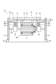
- FIG. 1 is a schematic front view showing a bogie according to a first embodiment.
- FIG. 2 is an explanatory diagram showing a state in which the bogie frame of FIG. 1 is displaced.
- FIG. 3 is a schematic diagram showing an example of the structure near the upper end of the guide portion.
- FIG. 4 is an explanatory diagram showing a first example of mounting the guide portion to the non-rotating portion of the axle.
- FIG. 5 is an explanatory diagram showing a second example of mounting the guide portion to the non-rotating portion of the axle.
- FIG. 6 is a schematic diagram for explaining the configuration of a motor bracket and a bogie frame in the bogie of the second embodiment.
- FIG. 7 is an explanatory diagram showing a state in which the bogie frame of FIG. 6 is displaced.
- FIG. 8 is a schematic diagram for explaining the configuration of a bogie frame in the bogie of the third embodiment.
- FIG. 9 is an explanatory diagram showing a state in which the bogie frame of FIG. 8 is displaced.
- FIG. 10 is a schematic diagram showing a bogie according to a first modified example.
- FIG. 11 is a schematic diagram showing a bogie according to a second modified example.
- Fig. 1 is a schematic front view showing the bogie of the first embodiment
- Fig. 2 is an explanatory diagram showing a state in which the bogie frame is displaced.
- the vertical direction is the up-down direction of the bogie 10
- the running direction of the bogie 10 is the front-rear direction
- the direction perpendicular to the running direction in a horizontal plane is the width direction of the bogie 10.
- the bogie 10 of the first embodiment is, for example, a bogie (running device) for a railway vehicle.
- the bogie 10 runs on a pair of rails RA that form a railway track.
- the bogie 10 is disposed under the car body 100 (see the dashed double-dashed line) of the railway vehicle, and supports the car body 100 from below.
- a space is provided inside the car body 100 for passengers to board and disembark.
- the bogie 10 comprises a bogie frame 20 , an axle 30 , a drive unit 40 , a joint unit 50 , and a guide unit 60 .
- the bogie frame 20 is a framework to which each component of the bogie 10 is assembled.
- the bogie frame 20 includes, for example, a pair of side beams 21 and a cross beam 22 connecting the pair of side beams 21.
- the pair of side beams 21 extend in the front-rear direction and are arranged at a distance in the width direction.
- the cross beam 22 extends in the width direction and both ends are connected to each of the pair of side beams 21.
- the bogie frame 20 is formed to extend mainly in the horizontal direction.
- the bogie frame 20 has a car body support portion 23 such as a bolster spring on the upper surface side, and supports the car body 100 via the car body support portion 23.
- the axle 30 is a rotating shaft member that is disposed below the bogie frame 20 and extends in the width direction. Wheels 31 are provided on both ends of the axle 30. The bogie 10 travels by each wheel 31 rotating on the rail RA as the axle 30 rotates.
- the axles 30 support the bogie frame 20 from below.
- the axles 30 include non-rotating parts 32 that support the bogie frame 20 via axle springs 33.
- the non-rotating parts 32 are bearing housings that house bearings that support the rotation of the axles 30.
- a pair of non-rotating parts 32 are provided near both ends of the axle 30, and the axle 30 is inserted through them.
- Axle springs 33 are provided on the top of each non-rotating part 32, and the bogie frame 20 is supported on the axle springs 33.
- at least one axle 30 is provided in the fore-aft direction of the bogie frame 20.
- the axle spring 33 is an elastic member that can elastically deform in the vertical direction, for example a compression coil spring.
- the axle spring 33 reduces the relative vibration in the vertical direction between the bogie frame 20 and the axle 30.
- the axle spring 33 elastically deforms in response to the load. This causes the bogie frame 20 to displace up and down relative to the axle 30.
- the wheels 31 and axle 30 displace up and down in response to the undulations of the rail RA, and the axle spring 33 elastically deforms in response to the displacement.
- the drive unit 40 includes a motor 41 and a motor bracket 42.
- FIG. 1 shows the internal structure of the motor 41 in cross section.
- the motor 41 is located below the bogie frame 20, between both ends of the axle 30.
- the motor 41 has a hollow shape, and the axle 30 is inserted into the hollow portion.
- the motor 41 is a so-called direct drive type motor, and directly drives the axle 30 via the joint part 50 without going through a reduction gear.
- the motor 41 has a stator 41a, a rotor 41b, and a bearing 41c.
- the stator 41a is formed in a cylindrical shape with a central axis that follows the axis of the axle 30.
- the rotor 41b is provided radially inside the stator 41a.
- the rotor 41b is formed in a cylindrical shape with a central axis that follows the axis of the axle 30.
- the rotor 41b is provided so as to be rotatable around the central axis by the bearing 41c.
- the rotor 41b is connected to the joint portion 50 at its axial end.
- the motor 41 rotates the rotor 41b around the central axis in response to the supply of power.
- the motor bracket 42 is a holding member that holds the motor 41, and is connected to the outer peripheral surface (upper surface) of the motor 41.
- the motor bracket 42 is supported by the bogie frame 20 in a state in which it can move relatively upward.
- the motor bracket 42 includes a support plate portion 43 extending horizontally, and a connecting portion 44 that extends downward from the lower surface of the support plate portion 43 and is connected to the motor 41.
- the support plate portion 43 is placed on the support surface SF of the bogie frame 20.
- the support surface SF is the upper surface (upper surface of the side beam 21) of the bogie frame 20. That is, the motor bracket 42 is supported from below by the bogie frame 20 (side beam 21) at both widthwise ends of the support plate portion 43.
- the connecting portion 44 passes through the space between a pair of side beams 21 of the bogie frame 20 and is connected to the motor 41.
- the motor bracket 42 (support plate portion 43) can move upward and away from the top surface of the bogie frame 20.
- the motor 41 is supported in a suspended state on the bogie frame 20 via the motor bracket 42.
- the motor bracket 42 is in contact with the upper surface of the bogie frame 20, the motor 41 is displaced vertically relative to the axle 30 together with the bogie frame 20.
- the joint unit 50 connects the motor 41 and the axle 30 so as to be capable of transmitting power.
- the joint unit 50 is disposed between the motor 41 and one of the non-rotating parts 32 (the right side in FIG. 1) in the width direction.
- the joint unit 50 includes an annular axle side member 51 and a coupling 52.
- the axle side member 51 is fixed to the axle 30 with the axle 30 inserted into its inner periphery.
- the outer periphery of the axle side member 51 faces the end face of the rotor 41b in the central axial direction (the width direction of the bogie 10) and is connected to the rotor 41b via the coupling 52.
- the joint unit 50 transmits the rotation of the rotor 41b to the axle 30.
- the coupling 52 is formed to be elastically deformable.
- the joint section 50 can absorb the relative displacement of the drive section 40 (motor 41) with respect to the axle 30 by elastically deforming the coupling 52. In other words, the joint section 50 can transmit power even when the central axis position of the motor 41 is displaced from the central axis position of the axle 30.
- a guide section 60 is provided so that the relative displacement of the drive section 40 (motor 41) with respect to the axle 30 does not exceed the displacement tolerance of the joint section 50.
- the displacement tolerance of the joint section 50 means the allowable value of the magnitude of the deviation between the central axis position of the motor 41 and the central axis position of the axle 30 in the vertical direction.
- the guide portion 60 is provided on the non-rotating portion 32 of the axle 30.
- the guide portion 60 comes into contact with the drive portion 40, restricting the displacement of the drive portion 40 relative to the axle 30.
- the guide portion 60 is provided on each of the non-rotating portions 32.
- the configuration of each guide portion 60 is the same.
- the guide portion 60 is provided on the side surface of each non-rotating portion 32 on the central side in the width direction of the bogie 10 (the motor 41 side).
- the guide portion 60 is a columnar or plate-like member extending upward from the non-rotating portion 32.
- the guide portion 60 passes through the inside of a pair of side beams 21 of the bogie frame 20 and extends to a predetermined position near the bottom surface of the motor bracket 42 (support plate portion 43).
- the guide portion 60 is provided so that the vertical distance between the upper end portion 61 of the guide portion 60 and the motor bracket 42 (support plate portion 43) is a predetermined amount PA.
- the guide portion 60 comes into contact with the underside of the motor bracket 42 (support plate portion 43) on the bogie frame 20, restricting (preventing) the downward displacement of the motor bracket 42.
- the guide portion 60 supports the entire drive portion 40, including the motor bracket 42, from below, and the support plate portion 43 of the motor bracket 42 is spaced a distance CL from the support surface SF of the bogie frame 20. Therefore, regardless of the amount of displacement of the bogie frame 20, the guide portion 60 limits the vertical relative displacement of the drive portion 40 (motor bracket 42 and motor 41) with respect to the axle 30 to within the predetermined amount PA in FIG. 1.
- the specified amount PA is smaller than the vertical displacement tolerance of the joint 50. Therefore, even if the motor 41 displaces up and down due to the relative displacement between the bogie frame 20 and the axle 30, the amount of displacement of the central axis of the motor 41 relative to the central axis of the axle 30 is limited to the specified amount PA, which is less than the vertical displacement tolerance of the joint 50.
- the predetermined amount PA may be zero.
- the upper end 61 of the guide portion 60 is positioned at approximately the same height as the support surface SF (upper surface) of the bogie frame 20 in the reference state shown in FIG. 1.
- the upper end 61 of the guide portion 60 can be provided in a state in which it is in contact with the motor bracket 42 that is not displaced.
- the reference state of the bogie frame 20 refers to, for example, a state in which the bogie 10 is assembled to a railway vehicle and the weight of the car body 100 other than the passengers acts on the bogie frame 20 (a state in which no passengers are on board).
- the amount of displacement of the bogie frame 20 is the amount of displacement from this reference state, and is zero in the reference state.
- the predetermined amount PA is non-zero.
- the guide portion 60 is provided in a position that is not in contact with the drive portion 40 (support plate portion 43 of the motor bracket 42) when the displacement of the bogie frame 20 relative to the axle 30 is less than the predetermined amount PA.
- a gap of the predetermined amount PA is provided between the upper end portion 61 of the guide portion 60 and the motor bracket 42.
- the weight of the drive unit 40 acts on the axle 30 via the bogie frame 20 and axle spring 33.
- the weight of the drive unit 40 is excluded from the "unsprung weight,” which is the weight below the axle spring 33, so the unsprung weight is reduced compared to, for example, a case where the drive unit 40 is directly supported by the axle 30.
- the guide portion 60 supports the motor bracket 42 (drive portion 40) as shown in FIG. 2, the weight of the drive portion 40 is supported by the axle 30 via the guide portion 60 (without via the axle spring 33), so the weight of the drive portion 40 is included in the unsprung weight.
- FIG. 3 is a schematic diagram showing an example of the structure of the upper end portion 61 and its vicinity of the guide portion 60. As shown in FIG. 3
- the guide portion 60 may have an abutment member 62 that is provided so as to be tiltable in any direction.
- the guide portion 60 may be provided with a spherical (hemispherical) sliding portion 63.
- the abutment member 62 has a spherical seat (spherical recess) 64 that fits into the sliding portion 63.
- the abutment member 62 tilts in any direction due to sliding between the spherical seat 64 and the sliding portion 63.
- the abutment member 62 can tilt to match the inclination of the motor bracket 42 and make surface contact, ensuring a stable contact state.
- the bogie frame 20 may have a guide member 24 that guides the relative displacement between the guide portion 60 and the bogie frame 20.
- the guide member 24 is fixed, for example, to the side beam 21 of the bogie frame 20.
- the guide member 24 has a cylindrical shape facing the vertical direction, and the guide portion 60 is slidably inserted into the inside.
- the guide member 24 supports the guide portion 60 so that it does not shift or tilt in the horizontal direction, while allowing relative vertical displacement between the bogie frame 20 and the guide portion 60 (axle 30).
- non-rotating portion 32, the carriage frame 20, and the motor bracket 42 may be provided with bushings, guide grooves, etc. to support the guide portion 60.
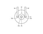
- FIG. 4 is an explanatory diagram showing a first example of mounting the guide portion 60 to the non-rotating portion 32 of the axle 30.
- FIG. 5 is an explanatory diagram showing a second example of mounting the guide portion 60 to the non-rotating portion 32 of the axle 30.
- one guide part 60 is attached to one non-rotating part 32.
- the lower end of the guide part 60 is fixed to the axial side of the housing 32a of the non-rotating part 32.
- the non-rotating part 32 supports the guide part 60 directly above the axle 30 (on a vertical line passing through the central axis of the axle 30).
- FIG. 5 shows an example in which multiple (two) guide portions 60 are attached to one non-rotating portion 32.
- the non-rotating portion 32 has a pair of mounting portions 32b and 32c that protrude forward and rearward, respectively, from the housing 32a. Furthermore, mounting portions 32b and 32c each support the lower end of one guide portion 60.
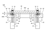
- Fig. 6 is a schematic diagram for explaining the configuration of the motor bracket 42A and the bogie frame 20A in the bogie 10A of the second embodiment.
- Fig. 7 is an explanatory diagram showing a state in which the bogie frame 20A of Fig. 6 is displaced. Note that in the second embodiment, other than the structure of the motor bracket 42A and the bogie frame 20A, the structure is the same as that of the first embodiment, and therefore the description will be omitted. Also, the same reference numerals are used for members having the same functions as those of the first embodiment, and detailed description will be omitted.
- the cart 10A according to the second embodiment further includes a first biasing member 70 that biases the drive unit 40 toward the guide unit 60 when the drive unit 40 and the guide unit 60 are in contact with each other.
- the first biasing member 70 is a compression coil spring.
- the first biasing member 70 may be an elastic body such as rubber or a cushion.
- the first biasing member 70 is provided in a compressed state between the head of the fixing bolt 71 and the upper surface of the motor bracket 42A.
- the first biasing member 70 is provided on both sides of the bogie frame 20A in the width direction (i.e., both side beams 21).
- the fixing bolt 71 is inserted into the inside of the first biasing member 70.
- the fixing bolt 71 passes through a through hole 45 formed in the motor bracket 42A and engages with a screw hole 25 formed in the support surface SF of the bogie frame 20A, thereby being fixed to the bogie frame 20A.
- the through hole 45 penetrates the support plate portion 43 in the vertical direction.
- the inner diameter of the through hole 45 is larger than the outer diameter of the shaft of the fixing bolt 71 and smaller than the outer diameter of the head of the fixing bolt 71. Therefore, the motor bracket 42A can be displaced in the vertical direction between the support surface SF, which is the upper surface of the bogie frame 20A, and the head of the fixing bolt 71.
- a bush with high sliding properties and wear resistance may be provided between the inner surface of the through hole 45 and the outer surface of the shaft of the fixing bolt 71.
- the first biasing member 70 biases the drive unit 40 (motor bracket 42A) downward toward the support surface SF of the bogie frame 20A.
- the first biasing member 70 exerts a downward biasing force F1 on the motor bracket 42A toward the support surface SF of the bogie frame 20A.
- the first biasing member 70 prevents the motor bracket 42A from moving away from the support surface SF of the bogie frame 20A due to the biasing force F1 in response to vibrations while the bogie 10A is traveling.
- a spacer may be provided between the first biasing member 70 and the motor bracket 42A to increase the amount of compression of the first biasing member 70.
- the bogie frame 20A is displaced downward relative to the axle 30 (see FIG. 1) by a predetermined amount PA or more.
- the motor bracket 42A comes into contact with the guide portion 60, thereby restricting the displacement of the drive portion 40 (motor bracket 42A and motor 41).
- the first biasing member 70 biases the drive portion 40 downward toward the guide portion 60 while the drive portion 40 is supported (restricted) by the guide portion 60.
- the guide portion 60 forms a gap CL between the motor bracket 42A and the support surface SF of the bogie frame 20A.
- the first biasing member 70 is compressed according to this gap CL, and biases the motor bracket 42A against the guide portion 60 with a biasing force F2 according to the amount of compression.
- the first biasing member 70 prevents the motor bracket 42A from separating from the guide portion 60 by the biasing force F2, even when the guide portion 60 vibrates up and down due to vibrations transmitted from the wheels 31 while the bogie 10A is traveling. In this way, the first biasing member 70 prevents the motor 41 from vibrating relative to the axle 30.
- Fig. 8 is a schematic diagram for explaining the configuration of the bogie frame 20B in the bogie 10B of the third embodiment.
- Fig. 9 is an explanatory diagram showing a state in which the bogie frame 20B of Fig. 8 is displaced. Note that, in the third embodiment, other than the structure of the bogie frame 20B, the third embodiment is similar to the second embodiment, and therefore the explanation is omitted. Also, the same reference numerals are used for members having the same functions as the second embodiment, and detailed explanations are omitted.
- the bogie 10B according to the third embodiment further includes a second biasing member 80.
- the second biasing member 80 is provided between the bogie frame 20B and the motor bracket 42A, and biases the motor bracket 42A in an upward direction away from the support surface SF of the bogie frame 20B.
- the second biasing member 80 is a compression coil spring.
- the second biasing member 80 may be an elastic body such as rubber or a cushion.
- the second biasing member 80 is provided in a compressed state between the lower surface of the motor bracket 42A and the upper surface of the bogie frame 20B.
- the second biasing member 80 is provided on both sides (both side beams 21) of the bogie frame 20B in the width direction.
- a recess 26 that accommodates the second biasing member 80 is formed on the upper surface (support surface SF) of the bogie frame 20B.
- the second biasing member 80 is disposed within the recess 26, and the shaft portion of the fixing bolt 71 is inserted into the inside.
- a screw hole 25 for fixing the fixing bolt 71 is formed in the bottom surface of the recess 26.
- the second biasing member 80 exerts an upward biasing force F3 on the motor bracket 42A, moving it away from the support surface SF of the bogie frame 20B.
- the biasing force F3 of the second biasing member 80 is smaller than the biasing force F1 of the first biasing member 70.
- the motor bracket 42A is pressed against the support surface SF by a downward biasing force whose magnitude is equivalent to the difference between the biasing forces F1 and F3, so that even when the bogie frame 20B vibrates up and down, the motor bracket 42A is prevented from moving away from the support surface SF.
- the second biasing member 80 still biases the motor bracket 42A upward even when the motor bracket 42A is supported on the guide portion 60 away from the support surface SF of the bogie frame 20B.
- the pre-compression amount by which the second biasing member 80 is pre-compressed in the reference state is greater than the predetermined amount PA for the motor bracket 42A to come into contact with the guide portion 60.
- the biasing force F4 of the second biasing member 80 acts as a support force with which the bogie frame 20B supports the motor bracket 42A.
- the second biasing member 80 reduces the load acting on the guide portion 60 from the motor bracket 42A by the biasing force F4.
- the weight acting on the guide portion 60 is included in the "unsprung weight” below the axle spring 33.
- the biasing force F4 of the second biasing member 80 is not included in the "unsprung weight” because it is supported by the non-rotating portion 32 of the axle 30 via the bogie frame 20B and the axle spring 33. Therefore, in the third embodiment, even when the weight of the motor bracket 42A (drive portion 40) is supported by the guide portion 60, the unsprung weight is reduced by the biasing force F4.
- the bogie of the first aspect comprises a bogie frame 20, an axle 30 including a non-rotating portion 32 supporting the bogie frame 20 via an axle spring 33, a hollow motor 41 through which the axle 30 is inserted, a motor bracket 42 holding the motor 41 and supported on the bogie frame 20 in a state where it can move relatively upwardly, a drive unit 40 including a coupling portion 50 that connects the motor 41 and the axle 30 so as to transmit power, and a guide portion 60 provided on the non-rotating portion 32 that abuts against the drive unit 40 when the bogie frame 20 is displaced by a predetermined amount PA or more relative to the axle 30, thereby regulating the displacement of the drive unit 40 relative to the axle 30.
- the weight of the drive unit 40 acts on the bogie frame 20 above the axle spring 33 by supporting the drive unit 40 on the bogie frame 20 in a state in which it can move relatively upward, so that the unsprung weight can be reduced compared to when the drive unit 40 is directly supported by the axle 30.
- the guide portion 60 abuts against the drive unit 40 to regulate the displacement of the drive unit 40 (i.e., the motor 41), so that the displacement of the motor 41 can be suppressed within the range of the predetermined amount PA.
- the increase in unsprung weight in the bogie 10 having a structure in which the motor 41 is directly connected to the axle 30 via the joint portion 50 can be suppressed, while the displacement tolerance required of the joint portion 50 can be reduced.
- the required design specifications of the joint portion 50 are relaxed, so that the degree of freedom in the design of the joint portion 50 can be increased.
- the stress amplitude acting on the joint part 50 is reduced, resulting in a longer life for the joint part 50.
- the bogie according to the second aspect further includes a first biasing member 70 that biases the drive unit 40 toward the guide unit 60 when the drive unit 40 and the guide unit 60 are in contact with each other.
- a first biasing member 70 that biases the drive unit 40 toward the guide unit 60 when the drive unit 40 and the guide unit 60 are in contact with each other.
- the bogie according to the third aspect further includes a second biasing member 80 that is provided between the bogie frame 20B and the motor bracket 42 and biases the motor bracket 42 in an upward direction away from the support surface SF of the bogie frame 20B.
- a second biasing member 80 that is provided between the bogie frame 20B and the motor bracket 42 and biases the motor bracket 42 in an upward direction away from the support surface SF of the bogie frame 20B.
- the predetermined amount PA is smaller than the allowable vertical displacement of the joint unit 50. This allows the relative displacement of the motor 41 with respect to the axle 30 to be kept within the range that the joint unit 50 can tolerate. In other words, by limiting the relative displacement of the motor 41 with respect to the axle 30 to within the predetermined amount PA, the amount of displacement that the joint unit 50 must tolerate can be reduced, so that the required design specifications for the joint unit 50 can be relaxed and the life of the joint unit 50 can be extended.
- the guide section 60 is provided in a position that is not in contact with the drive section 40 when the displacement of the bogie frame 20 relative to the axle 30 is less than a predetermined amount PA.
- the motor bracket 42 has been described as displacing relative to the wheel in parallel as shown in FIG. 2, etc. However, even if the motor bracket 42 displaces relative to only one side (i.e., the bogie frame 20 tilts with respect to the axle 30), the amount of displacement on that side can be limited by the guide portion 60, and the same effect as above can be obtained.
- FIG. 10 is a schematic diagram showing a bogie 10C according to a first modified example.
- the guide portion 60 abuts against the abutment piece 46 provided on the connecting portion 44 of the motor bracket 42 to restrict the displacement of the drive portion 40 relative to the axle 30.
- the guide portion 60 is configured by an L-shaped bracket that extends upward from the non-rotating portion 32 of the axle 30 and is bent inward in the width direction at its upper end.
- the abutment piece 46 protrudes outward in the width direction from the side surface on the outer side of the connecting portion 44 in the width direction to an upper position of the guide portion 60.
- the guide unit 60 abuts against the abutment piece 46 to regulate the displacement of the drive unit 40 and support the drive unit 40.
- the guide unit 60 may abut against, for example, a part of the housing of the motor 41 or an abutment piece provided on the housing.
- the guide portion 60 does not have to be provided separately from the non-rotating portion 32 of the axle 30.
- the guide portion 60 may be a protrusion formed integrally with the non-rotating portion 32 (bearing housing).
- the motor bracket 42 (support plate portion 43) is placed on the upper surface of the bogie frame 20 (the upper surface of the bogie frame 20 is the support surface SF), but the motor bracket 42 may be placed on a portion other than the upper surface of the bogie frame 20.
- the motor bracket 42 is supported by an L-shaped support bracket 27 provided on the inner side surface of the side beam 21 of the bogie frame 20.
- the upper surface of the tip of the support bracket 27 is the support surface SF.
- the motor bracket 42 may be supported at a lower position than the bogie frame 20 (side beam 21) by a bracket or the like.
- FIG. 11 is a schematic diagram showing a bogie 10D according to a second modified example in which the non-rotating portion 32, the axle spring 33, and the guide portion 60 are arranged on the outside of the pair of wheels 31.
- the joint part 50 is a flexible joint having an elastically deformable coupling 52, but the structure of the joint part 50 is not particularly limited, and it may be a joint other than a flexible joint.
Landscapes
- Engineering & Computer Science (AREA)
- Mechanical Engineering (AREA)
- Chemical & Material Sciences (AREA)
- Combustion & Propulsion (AREA)
- Transportation (AREA)
- Vehicle Body Suspensions (AREA)
- Arrangement Or Mounting Of Propulsion Units For Vehicles (AREA)
- Platform Screen Doors And Railroad Systems (AREA)
Abstract
Description
図1は、第1実施形態の台車を表す模式的な正面図、図2は、台車フレームが変位した状態を示した説明図である。なお、以下の説明にて、鉛直方向を台車10の上下方向とし、台車10の走行方向を前後方向とし、水平面内で走行方向と直交する方向を台車10の幅方向として説明する。
台車10は、台車フレーム20と、車軸30と、駆動部40と、継手部50と、ガイド部60と、を備える。
図3は、ガイド部60の上端部61付近の構造例を示した模式図である。
図6は、第2実施形態の台車10Aにおけるモータブラケット42Aおよび台車フレーム20Aの構成を説明するための模式図である。図7は、図6の台車フレーム20Aが変位した状態を示した説明図である。なお、第2実施形態において、モータブラケット42Aおよび台車フレーム20Aの構造以外は、上記第1実施形態と同様であるので、説明を省略する。また、上述した第1実施形態と同様の機能を有する部材には、同一の符号を付して詳細な説明は省略する。
図8は、第3実施形態の台車10Bにおける台車フレーム20Bの構成を説明するための模式図である。図9は、図8の台車フレーム20Bが変位した状態を示した説明図である。なお、第3実施形態において、台車フレーム20Bの構造以外は、上記第2実施形態と同様であるので、説明を省略する。また、上述した第2実施形態と同様の機能を有する部材には、同一の符号を付して詳細な説明は省略する。
第1の態様に係る台車は、台車フレーム20と、軸ばね33を介して台車フレーム20を支持する非回転部32を含む、車軸30と、車軸30が挿通された中空形状のモータ41と、モータ41を保持し、上方向に相対移動可能な状態で台車フレーム20に支持されたモータブラケット42と、を含む、駆動部40と、モータ41と車軸30とを、動力伝達可能に連結する継手部50と、非回転部32に設けられ、台車フレーム20が車軸30に対して所定量PA以上変位した場合に駆動部40と当接して、駆動部40の車軸30に対する変位を規制するガイド部60と、を備える。
なお、上述した実施形態では、ガイド部60が、駆動部40のうち、モータブラケット42(支持板部43)の下面と当接して、駆動部40の変位を規制する例を示したが、ガイド部60は、駆動部40のどの部位と当接してもよい。図10は、第1変形例による台車10Cを示した模式図である。図10の例では、ガイド部60が、モータブラケット42の連結部44に設けた当接片46と当接することにより、駆動部40の車軸30に対する変位を規制する。この例では、ガイド部60は、車軸30の非回転部32から上方に延びた後、上端部で幅方向内側に屈曲したL字状のブラケットにより構成されている。そして、当接片46は、連結部44の幅方向外側の側面から、ガイド部60の上方位置まで、幅方向外側に向けて突出する。これにより、台車フレーム20の下方変位に伴って駆動部40が下方変位すると、ガイド部60が当接片46と当接して駆動部40の変位を規制するとともに駆動部40を支持する。この他、ガイド部60は、例えばモータ41のハウジングの一部、またはハウジングに設けた当接片と当接してもよい。
20、20A、20B 台車フレーム
30 車軸
32 非回転部
40 駆動部
41 モータ
42、42A モータブラケット
50 継手部
60 ガイド部
70 第1付勢部材
80 第2付勢部材
PA 所定量
SF 支持面
Claims (5)
- 台車フレームと、
軸ばねを介して前記台車フレームを支持する非回転部を含む、車軸と、
前記車軸が挿通された中空形状のモータと、前記モータを保持し、上方向に相対移動可能な状態で前記台車フレームに支持されたモータブラケットと、を含む、駆動部と、
前記モータと前記車軸とを、動力伝達可能に連結する継手部と、
前記非回転部に設けられ、前記台車フレームが前記車軸に対して所定量以上変位した場合に前記駆動部と当接して、前記駆動部の前記車軸に対する変位を規制するガイド部と、を備える、
台車。 - 前記駆動部と前記ガイド部とが当接した状態で、前記駆動部を前記ガイド部に向けて付勢する第1付勢部材をさらに備える、
請求項1に記載の台車。 - 前記台車フレームと前記モータブラケットとの間に設けられ、前記モータブラケットを前記台車フレームの支持面から離れる上方向に付勢する第2付勢部材をさらに備える、
請求項2に記載の台車。 - 前記所定量は、前記継手部の上下方向の変位許容量よりも小さい、
請求項1~3のいずれか1項に記載の台車。 - 前記ガイド部は、前記台車フレームの前記車軸に対する変位が前記所定量未満の場合に、前記駆動部と非接触となる位置に設けられている、
請求項1~3のいずれか1項に記載の台車。
Priority Applications (1)
| Application Number | Priority Date | Filing Date | Title |
|---|---|---|---|
| EP24796491.9A EP4610140A4 (en) | 2023-04-28 | 2024-02-01 | TRUCK |
Applications Claiming Priority (2)
| Application Number | Priority Date | Filing Date | Title |
|---|---|---|---|
| JP2023-074237 | 2023-04-28 | ||
| JP2023074237A JP2024158744A (ja) | 2023-04-28 | 2023-04-28 | 台車 |
Publications (1)
| Publication Number | Publication Date |
|---|---|
| WO2024224732A1 true WO2024224732A1 (ja) | 2024-10-31 |
Family
ID=93255999
Family Applications (1)
| Application Number | Title | Priority Date | Filing Date |
|---|---|---|---|
| PCT/JP2024/003231 Ceased WO2024224732A1 (ja) | 2023-04-28 | 2024-02-01 | 台車 |
Country Status (3)
| Country | Link |
|---|---|
| EP (1) | EP4610140A4 (ja) |
| JP (1) | JP2024158744A (ja) |
| WO (1) | WO2024224732A1 (ja) |
Citations (4)
| Publication number | Priority date | Publication date | Assignee | Title |
|---|---|---|---|---|
| JPH1148965A (ja) * | 1997-08-07 | 1999-02-23 | Hitachi Ltd | 鉄道車両用台車 |
| JP2005059616A (ja) | 2003-08-11 | 2005-03-10 | East Japan Railway Co | 車両用主電動機の継手型駆動装置 |
| CN101683855A (zh) * | 2009-04-24 | 2010-03-31 | 大连交通大学 | 新型机车牵引传动装置 |
| CN207902426U (zh) * | 2018-01-26 | 2018-09-25 | 大连交通大学 | 单空心轴轨道车辆永磁直驱全悬挂牵引传动装置 |
Family Cites Families (3)
| Publication number | Priority date | Publication date | Assignee | Title |
|---|---|---|---|---|
| JPH11301471A (ja) * | 1998-04-20 | 1999-11-02 | Nippon Seiko Kk | 鉄道車両用直接駆動式電動台車 |
| EP3470288B1 (de) * | 2017-10-10 | 2021-02-03 | Siemens Mobility GmbH | Schienenfahrzeug mit kompaktem direktantrieb |
| CN213920991U (zh) * | 2020-09-10 | 2021-08-10 | 中车工业研究院有限公司 | 三点架悬式转向架 |
-
2023
- 2023-04-28 JP JP2023074237A patent/JP2024158744A/ja active Pending
-
2024
- 2024-02-01 EP EP24796491.9A patent/EP4610140A4/en active Pending
- 2024-02-01 WO PCT/JP2024/003231 patent/WO2024224732A1/ja not_active Ceased
Patent Citations (4)
| Publication number | Priority date | Publication date | Assignee | Title |
|---|---|---|---|---|
| JPH1148965A (ja) * | 1997-08-07 | 1999-02-23 | Hitachi Ltd | 鉄道車両用台車 |
| JP2005059616A (ja) | 2003-08-11 | 2005-03-10 | East Japan Railway Co | 車両用主電動機の継手型駆動装置 |
| CN101683855A (zh) * | 2009-04-24 | 2010-03-31 | 大连交通大学 | 新型机车牵引传动装置 |
| CN207902426U (zh) * | 2018-01-26 | 2018-09-25 | 大连交通大学 | 单空心轴轨道车辆永磁直驱全悬挂牵引传动装置 |
Non-Patent Citations (1)
| Title |
|---|
| See also references of EP4610140A4 |
Also Published As
| Publication number | Publication date |
|---|---|
| EP4610140A4 (en) | 2026-04-15 |
| EP4610140A1 (en) | 2025-09-03 |
| JP2024158744A (ja) | 2024-11-08 |
Similar Documents
| Publication | Publication Date | Title |
|---|---|---|
| EP4197877A1 (en) | Frame, bogie, and rail vehicle | |
| JP6034254B2 (ja) | 鉄道車両用台車 | |
| CN112519827B (zh) | 转向架横梁、转向架及轨道车辆 | |
| JP6718237B2 (ja) | ブレーキユニットを備えた鉄道車両用操舵台車 | |
| JP6004996B2 (ja) | 鉄道車両用台車 | |
| JP2013189097A (ja) | 軌条車両 | |
| CN111994109B (zh) | 转向架及轨道车辆 | |
| JP3383805B2 (ja) | 車体と下部構造の間に連結要素ユニットを有するレール車両 | |
| JP2011213148A (ja) | 鉄道車両及び鉄道車両用台車 | |
| US3181479A (en) | Lightweight truck | |
| JP6309596B1 (ja) | 鉄道車両用軸箱支持装置 | |
| JPH07172314A (ja) | 鉄道車両及び鉄道車両用台車 | |
| US12365368B2 (en) | Bogie for a rail vehicle and rail vehicle carriage having at least one bogie, rail vehicle having at least one rail vehicle carriage, and method for adjusting the height of a carriage body of a rail vehicle carriage | |
| WO2024224732A1 (ja) | 台車 | |
| JP3265153B2 (ja) | 鉄道車両の軌間可変台車 | |
| RU2726675C2 (ru) | Ходовая часть рельсового транспортного средства | |
| CN111994113A (zh) | 转向架及轨道车辆 | |
| KR102479239B1 (ko) | 철도차량용 림 대차 | |
| JP3346347B2 (ja) | リニアモータを用いた鉄道車両用台車 | |
| JP2008230488A (ja) | 鉄道車両用台車の軸箱支持装置及び台車 | |
| US5537932A (en) | Railway truck bearing lateral thrust pads | |
| JP6339928B2 (ja) | 鉄道車両用台車 | |
| JPH09315297A (ja) | 案内軌道車の走行装置 | |
| JPH07149236A (ja) | 鉄道車両用台車の軸梁式軸箱支持装置 | |
| CN111976774B (zh) | 一种空心轴式一系悬挂装置 |
Legal Events
| Date | Code | Title | Description |
|---|---|---|---|
| 121 | Ep: the epo has been informed by wipo that ep was designated in this application |
Ref document number: 24796491 Country of ref document: EP Kind code of ref document: A1 |
|
| WWE | Wipo information: entry into national phase |
Ref document number: 2024796491 Country of ref document: EP Ref document number: 24796491.9 Country of ref document: EP |
|
| ENP | Entry into the national phase |
Ref document number: 2024796491 Country of ref document: EP Effective date: 20250529 |
|
| WWP | Wipo information: published in national office |
Ref document number: 2024796491 Country of ref document: EP |
|
| NENP | Non-entry into the national phase |
Ref country code: DE |