WO2024224739A1 - Soupape électrique - Google Patents
Soupape électrique Download PDFInfo
- Publication number
- WO2024224739A1 WO2024224739A1 PCT/JP2024/003996 JP2024003996W WO2024224739A1 WO 2024224739 A1 WO2024224739 A1 WO 2024224739A1 JP 2024003996 W JP2024003996 W JP 2024003996W WO 2024224739 A1 WO2024224739 A1 WO 2024224739A1
- Authority
- WO
- WIPO (PCT)
- Prior art keywords
- valve
- rotor
- valve body
- motor
- bearing member
- Prior art date
- Legal status (The legal status is an assumption and is not a legal conclusion. Google has not performed a legal analysis and makes no representation as to the accuracy of the status listed.)
- Ceased
Links
Images



Classifications
-
- F—MECHANICAL ENGINEERING; LIGHTING; HEATING; WEAPONS; BLASTING
- F16—ENGINEERING ELEMENTS AND UNITS; GENERAL MEASURES FOR PRODUCING AND MAINTAINING EFFECTIVE FUNCTIONING OF MACHINES OR INSTALLATIONS; THERMAL INSULATION IN GENERAL
- F16K—VALVES; TAPS; COCKS; ACTUATING-FLOATS; DEVICES FOR VENTING OR AERATING
- F16K27/00—Construction of housing; Use of materials therefor
- F16K27/02—Construction of housing; Use of materials therefor of lift valves
-
- F—MECHANICAL ENGINEERING; LIGHTING; HEATING; WEAPONS; BLASTING
- F16—ENGINEERING ELEMENTS AND UNITS; GENERAL MEASURES FOR PRODUCING AND MAINTAINING EFFECTIVE FUNCTIONING OF MACHINES OR INSTALLATIONS; THERMAL INSULATION IN GENERAL
- F16K—VALVES; TAPS; COCKS; ACTUATING-FLOATS; DEVICES FOR VENTING OR AERATING
- F16K31/00—Actuating devices; Operating means; Releasing devices
- F16K31/02—Actuating devices; Operating means; Releasing devices electric; magnetic
- F16K31/04—Actuating devices; Operating means; Releasing devices electric; magnetic using a motor
Definitions
- the present invention relates to an electric valve, and in particular to a reinforcing structure for a can (sealed container) that houses the rotor of an electric motor.
- Electric valves that use an electric motor such as a stepping motor to adjust the valve opening and control the flow rate of refrigerant have traditionally been used in refrigeration cycle equipment with refrigerant circuits, such as air conditioners and refrigeration/freezing equipment.
- FIG. 7 shows an example of such an electric valve.
- the electric valve 41 includes a valve body 12 having a valve chamber 13 and an orifice 16 therein, and connected to a first flow pipe 14 and a second flow pipe 15 that communicate with the valve chamber 13, a valve element 17 that moves back and forth (up and down) relative to the orifice 16 to change the flow rate of the fluid, a can 19 that forms a sealed space above the valve body 12, an electric motor 21 that drives the valve element 17, a speed reduction mechanism 31 that reduces the rotation of the electric motor 21, and a transmission mechanism 32 that converts the rotation reduced by the speed reduction mechanism 31 into linear motion and transmits it to the valve element 17.
- the electric motor 21 has a rotor 27 and a stator 22.
- the rotor 27 is housed in the can 19 and rotatably supported by a support shaft member 28 and a bearing member (upper bearing member) 42.
- the stator 22 is covered by a resin molded cover 26 and is arranged on the outside (outer periphery) of the can 19.
- the lower end of the can 19 is fixed by welding to the step 12c at the top of the valve body via a ring-shaped base plate 18.
- the internal space of the can 19 is connected to the valve chamber 13, and the refrigerant flows into the can 19.
- Patent Document 1 JP-A-11-6577 Patent Document 2: JP-A-2007-211814 Patent Document 3: JP-A-2008-101633 Patent Document 4: JP-A-2012-197849
- the operating pressure of CO2 refrigerant is higher than that of conventional fluorocarbon refrigerants, and the use of high-pressure refrigerants such as CO2 requires the can to have high strength (rigidity).
- the strength requirement was met by increasing the thickness of the lower end (welded part) 54b of the can 54 and making the top surface 54a spherical to prevent deformation, as shown in Figure 8.
- the reason for making the lower end 54b thick is to reinforce the lower end (welded part), which serves as a fulcrum during elastic deformation and causes stress concentration.
- top surface 54a spherical increases the height of the can 54 (length in the direction of axis A), which makes the motor-operated valve 51 larger (higher in height).
- the conventional stator 22 shown in FIG. 7 cannot be used, and a dedicated stator 52 (equipped with a resin molded cover 53 of a different shape) must be prepared, which increases manufacturing costs.
- the object of the present invention is therefore to improve the rigidity (pressure resistance) of the can without changing the shape or height of the can top surface, making it compatible with high-pressure refrigerants.
- the motor-operated valve of the present invention is an electric valve comprising a valve body having a valve chamber and an orifice therein and connected to a first flow path and a second flow path communicating with the valve chamber, a valve element that moves back and forth relative to the orifice to change the flow rate of fluid passing through the orifice, a can that communicates with the valve chamber and houses the rotor of an electric motor that drives the valve element, and a bearing member that is disposed on top of the rotor inside the can and rotatably supports the rotor, the bearing member having a plurality of joints that contact the inner surface of the top plate of the can and are joined to said inner surface.
- the bearing member typically has a bearing body portion into which a support shaft member that rotatably supports the rotor is inserted, a flange portion that protrudes from the bearing body portion, and a rib that rises from the upper surface of the flange portion toward the top plate portion of the can, with the flange portion abutting the inner peripheral surface of the can and the joint portion being formed on the rib.
- the can is reinforced by using a bearing member provided at the upper part (ceiling) inside the can.
- the bearing member is configured to contact the inner surface of the top plate of the can, and multiple points of the bearing member that contact the inner surface are joined to the inner surface of the top plate of the can, thereby suppressing deformation of the can and improving the pressure resistance of the can.
- top plate of the can refers to the part that covers the top of a bottomless, lidless can (i.e., the bottom is open and the top is closed), and more specifically, it is as follows.
- the can has a cylindrical portion with a constant diameter, including the portion interposed between the rotor and stator, and a tapered portion whose diameter gradually decreases to close the top surface.
- the tapered portion may include a curved plate portion with curved inner and outer surfaces, and may include multiple curved plate portions with different curvatures.
- the tapered portion may also include a flat plate portion with flat inner and outer surfaces (flat plate-like).
- the deformation of the can top surface due to the high-pressure refrigerant occurs at the boundary between the cylindrical portion and the reduced diameter portion (the ring-shaped outer edge of the reduced diameter portion that extends upward and inward from the top end of the cylindrical portion), or in other words, at the ring-shaped corner portion that forms the outer edge of the can top surface. Therefore, in this invention, the portion inside and above the boundary portion (corner portion) is called the "top plate portion," and by joining a bearing member to this top plate portion, deformation of the can (top plate portion) is suppressed and the pressure resistance of the can is improved.
- the above terms “inside” and “inner” refer to the side closer to the central axis of the can.
- the axial direction of the motor-operated valve (valve body) and the can is referred to as the "vertical direction", with one of these vertical directions (the direction from the valve body toward the can) referred to as “up” and the other vertical direction (the direction from the can toward the valve body) referred to as “down”.
- up and down terms related to up and down, such as “above” and “below”, “upper” and “lower”, “upper side” and “lower side”, are used in this application.
- the motor-operated valve of the present invention can be used in various orientations, so “down” does not necessarily mean the direction of gravity and "up” does not necessarily mean the direction opposite to gravity.
- the bearing member and the inner surface of the can top plate are preferably joined by welding, and in particular by electric resistance welding, since this provides a joint strength that can maintain the joint even with repeated elastic deformation caused by temperature changes and pressure fluctuations.
- welding and in particular by electric resistance welding, since this provides a joint strength that can maintain the joint even with repeated elastic deformation caused by temperature changes and pressure fluctuations.
- the joining is not limited to welding, and methods other than welding (e.g. brazing) can also be used.
- the above-mentioned joints in the present invention are formed in rotationally symmetrical positions. This is to ensure that a uniform load is applied to the can top plate (each joint) when high pressure is applied inside the can.
- the flange portion has an opening that penetrates it in the axial direction. This is to prevent a pressure difference from occurring between the upper and lower sides of the bearing member.
- the strength (rigidity) of the can can be improved. Therefore, it is possible to handle high-pressure refrigerants without increasing the size of the motor-operated valve (lengthening the can).
- the stator can be shared between motor-operated valves that use conventional refrigerants such as fluorocarbon-based refrigerants and motor-operated valves that are compatible with high-pressure refrigerants such as CO2 refrigerants, and the increase in costs required to handle high-pressure refrigerants can be suppressed.
- the present invention it is possible to improve the pressure resistance of the can without changing the shape or height of the top plate of the can, making it possible to accommodate high-pressure refrigerants.
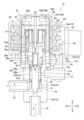
- FIG. 1 is a vertical cross-sectional view showing a motor-operated valve (closed state) according to one embodiment of the present invention.
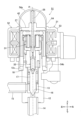
- FIG. 2 is a vertical cross-sectional view showing the motor-operated valve (in an open state) according to the embodiment.
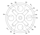
- FIG. 3 is a plan view showing a bearing member provided in the motor-operated valve according to the embodiment.
- FIG. 4 is a vertical cross-sectional view (cross-section BB of FIG. 3) showing a bearing member provided in the motor-operated valve according to the embodiment.
- FIG. 5 is a plan view showing another bearing member provided in the motor-operated valve according to the embodiment.
- FIG. 6 is a vertical cross-sectional view (cross-section CC in FIG.
- FIG. 7 is a vertical cross-sectional view showing an example of a conventional motor-operated valve.
- FIG. 8 is a vertical sectional view showing another example of a conventional motor-operated valve.
- an electric valve 11 can be used to adjust the flow rate of a refrigerant in a refrigeration cycle device such as a heat pump type heating and cooling system, and includes a valve body 12 having a valve chamber 13 and an orifice (a valve port with a valve seat at its upper end) 16 therein, a valve element 17 that is provided so as to be movable forward and backward (up and down) relative to the orifice 16, an electric motor 21 that drives the valve element 17, a speed reduction mechanism 31 that reduces the rotation of the electric motor 21, a transmission mechanism 32 that converts the rotation reduced by the speed reduction mechanism 31 into linear motion and transmits it to the valve element 17, and a can (sealed container) 19 that forms an airtight space above the valve body 12.
- a valve body 12 having a valve chamber 13 and an orifice (a valve port with a valve seat at its upper end) 16 therein
- a valve element 17 that is provided so as to be movable forward and backward (up and down) relative to the orifice 16
- the valve body 12 has a main body portion 12a that forms the valve chamber 13, and a cylindrical connection portion 12b that extends upward from the upper end of the main body portion 12a and allows connection of an electric motor 21 (can 19).
- An orifice 16 is formed on the upper surface of the bottom of the main body portion 12a, and a first flow path pipe 14 is connected to the bottom surface of the main body portion 12a so as to communicate with the valve chamber 13 via the orifice 16.
- a second flow path pipe 15 is connected to the side of the main body portion 12a so as to communicate with the valve chamber 13.
- the first flow path pipe 14 is used as the inflow path of the refrigerant
- the second flow path pipe 15 is used as the outflow path of the refrigerant
- the connecting portion 12b has a smaller outer diameter than the main body portion 12a.
- a step 12c is formed at the boundary between the main body portion 12a and the connecting portion 12b on the outer circumferential surface of the valve body 12.
- the lower end of the can 19 is joined (welded) to this step 12c via a ring-shaped base plate 18, integrating the can 19 and the valve body 12.
- the lower end of the can 19, which is the joint, is made into a thick portion 19e with a larger thickness to increase pressure resistance.
- the can 19 is a bottomless, lidded cylindrical member (with an open bottom and closed top) formed by pressing a conductive metal plate (e.g., stainless steel plate), and has a cylindrical section 19a with a constant inner diameter and a tapered section 19b with a gradually decreasing inner diameter to close the top.
- the tapered section 19b has a corner section 19c, which is a ring-shaped section that spreads upward and inward from the upper end of the cylindrical section 19a, and a disk-shaped (dome-shaped like a pot bottom ceiling) top plate section 19d (can ceiling section 19d) that spreads inside the corner section 19c and completely blocks the top surface of the can 19.
- the corner section 19c which connects the cylindrical section 19a and the top plate section 19d, has a larger curvature (smaller radius of curvature) than the top plate section 19d in order to keep the height of the can 19 low.
- Top plate portion 19d is the center of the top surface of the can, that is, the portion that spreads out in a perfect circle when viewed from above, centered on the central axis A of the can 19, but if this range (the size of top plate portion 19d) is expressed numerically with the inner diameter of the can 19 (cylindrical portion 19a) being r (see Figure 1), in this embodiment, the portion within a range of 0.95r centered on the central axis A of the can 19 is defined as the "top plate portion.”
- An upper bearing member 29 (described in detail later) is then joined to the inner surface of this range (top plate portion 19d).
- the electric motor 21 that drives the valve body 17 is a stepping motor.
- This stepping motor 21 is made up of a stator 22 installed on the outside (outer circumference) of the can 19 and a rotor 27 rotatably installed on the inside (inner circumference) of the can 19.
- the stator 22 has a yoke 23, a coil 25 with a winding wound around a bobbin 24, and a resin molded cover 26 that covers the yoke 23 and the coil 25.
- the rotor 27 is rotatably supported by a round bar-shaped support shaft member 28 that extends vertically through the center of the can 19 along the central axis A.
- the lower end of the support shaft member 28 is fitted so as to be relatively rotatable into the upper part of an output shaft 33 (described later) that outputs the rotation of the rotor 27, and the upper end is supported by an upper bearing member 29.
- This upper bearing member 29 corresponds to the bearing member referred to in this invention.
- the upper bearing member 29 (see also Figures 3 and 4) has a cylindrical bearing body 29a into which the upper end of the support shaft member 28 is inserted and fixed, a disk-shaped flange 29b that spreads outward horizontally from the lower end of the bearing body 29a, and four ribs 29c that rise vertically upward from the upper surface of the flange 29b and extend radially in all directions from the outer circumferential surface of the bearing body 29a, and is made of a conductive metal material (e.g., stainless steel).
- the flange 29b between the ribs 29c has an opening 29e that penetrates in the axial direction, so that no pressure difference occurs between the top and bottom of the upper bearing member 29.
- the flange portion 29b has an outer diameter that is approximately the same as the inner diameter of the can 19 (cylindrical portion 19a), and the outer peripheral surface of the flange portion 29b abuts against the upper inner peripheral surface of the cylindrical portion 19a of the can 19. Furthermore, each rib 29c has a protrusion 29d with a semispherical cross-sectional shape that protrudes upward at the outer end of its upper surface, and these protrusions 29d abut against the inner surface of the can top plate portion 19d. These protrusions 29d are then joined to the inner surface of the can top plate portion 19d.
- This joining is performed by resistance welding in which an electric current is passed through the contact portion between the two base materials (the can top plate portion 19d and the protrusions 29d of the upper bearing member 29) while pressing the protrusions 29d against the inner surface of the can top plate portion 19d. Furthermore, the resistance welding is performed by pulse welding in which a pulse current is supplied as the welding current. This is to obtain strong joining strength through deep penetration.
- the ceiling portion 19d is less likely to deform even when high pressure is applied inside the can, improving the strength of the can.
- the protrusion 29d to the top plate portion 19d with the outer peripheral surface of the flange portion 29b abutting the upper inner peripheral surface of the cylindrical portion 19a, the function of suppressing axial wobble and tilt of the support shaft member 28 is improved. In other words, horizontal positional deviation of the rotor 27 and contact between the rotor 27 and the inner wall of the can can be suppressed.
- the rotor 27 is provided with a paradoxical planetary gear mechanism that has a high reduction ratio and is advantageous for miniaturization as the reduction mechanism 31 inside the rotor 27.
- the rotation of the rotor 27 is reduced in speed by the reduction mechanism 31, and is transmitted to the output shaft 33 provided at the center of the underside of the rotor 27, and is output from the output shaft 33.
- a cylindrical lower bearing member 34 is disposed under the rotor 27, and this lower bearing member 34 rotatably supports the output shaft 33.
- the lower bearing member 34 is inserted and fixed into the connection portion 12b of the valve body 12.
- a fitting hole 34a is formed in the center of the upper surface of the lower bearing member 34, and the output shaft 33 is rotatably inserted into this fitting hole 34a.
- a female thread 34b is formed in the lower center of the lower bearing member 34, and a male thread 35a formed on the outer circumferential surface of the screw drive member 35 is screwed into this female thread 34b.
- the lower bearing member 34 (female thread 34b) and the screw drive member 35 (male thread 35a) form a feed screw mechanism, and constitute the transmission mechanism 32 that converts the rotational motion supplied from the stepping motor 21 via the reduction mechanism 31 into linear motion in the vertical direction and transmits it to the valve body 17.
- the rotor 27 and output shaft 33 rotate at a fixed position in the vertical direction without moving up and down, and a flat screwdriver-shaped plate-shaped portion 35b provided at the upper end of the screw drive member 35 is inserted into a slit-shaped fitting groove 33a provided at the lower end of the output shaft 33 to transmit the rotational motion of the rotor 27 (output shaft 33) to the screw drive member 35.
- the plate-shaped portion 35b provided on the screw drive member 35 slides up and down within the fitting groove 33a of the output shaft 33, so that when the rotor 27 rotates, the screw drive member 35 moves linearly up and down due to the screw feed mechanism 32, even though the output shaft 33 does not move up and down.
- valve body 17 is a cylindrical member with a needle-shaped (inverted cone-shaped) tip at its lower end that moves in and out of contact with (abuts against) the orifice (valve seat) 16 so as to be inserted into the orifice, and has a flange portion 17a that projects outward horizontally at its upper end.
- a fitting hole 17b is formed in the upper surface of the valve body 17, and the ball seat 36b is fitted into this fitting hole 17b.
- a stepped cylindrical valve body guide member 37 is provided within the valve chamber 13.
- This valve body guide member 37 consists of a guide portion 37a with a small diameter (inner diameter and outer diameter) formed at the lower end, a ring-shaped flange portion 37c that spreads horizontally outward from the upper end, and a large diameter portion 37b with a large diameter (inner diameter and outer diameter) formed in the middle portion (between the guide portion 37a and the flange portion 37c).
- the guide portion 37a supports the valve body 17 so that it can slide up and down.
- the large diameter portion 37b has an outer diameter approximately equal to the inner diameter of the main body portion 12a (valve chamber 13) of the valve body 12, and is nested and fixed into the valve chamber 13 so as to be in close contact with the inner circumferential surface of the valve chamber 13.
- the flange portion 37c is arranged to rest on a step portion 12d formed on the lower end of the inner circumferential surface of the connection portion 12b of the valve body 12, and is sandwiched between the step portion 12d and the lower bearing member 34, thereby preventing the valve body guide member 37 from shifting in the vertical direction.
- a step portion 37d is formed on the inner circumferential surface of the valve body guide member 37 between the large diameter portion 37b and the guide portion 37a.
- a compression coil spring 38 is provided inside the large diameter portion 37b, more specifically, in the gap between the outer peripheral surface of the valve body 17 and the inner peripheral surface of the large diameter portion 37b.
- This compression coil spring 38 is placed in a compressed state between the flange portion 17a of the valve body 17 and the step portion 37d of the valve body guide member 37 to bias the valve body 17 upward (in the valve opening direction).
- the biasing force of the compression coil spring 38 is applied to the valve body 17 in addition to the driving force of the electric motor 21, thereby more reliably opening the valve.
- the central axis A of the valve body 12 (body portion 12a and connection portion 12b), can 19, orifice 16, valve body 17, ball joint 36, support shaft member 28, upper bearing member 29, and lower bearing member 34, as well as the central axis (rotation axis) A of the rotor 27, output shaft 33, and screw drive member 35, are aligned with one another.
- This upper bearing member 39 has a bearing body 39a and a flange 39b similar to those of the upper bearing member 29, but instead of the ribs 29c extending radially in all directions, it has a ring-shaped rib 39c extending in a perfect circle around the central axis A.
- the ring-shaped rib 39c stands vertically upward from the upper surface of the flange 39b, and its upper end abuts the inner surface of the can top plate 19d.
- the number of joints 39d may be, for example, three or five or more. It is preferable that the multiple joints 39d are rotationally symmetrical.
Landscapes
- Engineering & Computer Science (AREA)
- General Engineering & Computer Science (AREA)
- Mechanical Engineering (AREA)
- Electrically Driven Valve-Operating Means (AREA)
- Valve Housings (AREA)
- Sliding Valves (AREA)
Abstract
L'invention concerne une soupape électrique comprenant : un corps de soupape 12 ayant une chambre de soupape 13 et un orifice 16 à l'intérieur de celui-ci et ayant un premier passage d'écoulement 14 et un second passage d'écoulement 15 communiquant avec la chambre de soupape ; un corps de soupape 17 qui se déplace vers l'avant et vers l'arrière par rapport à l'orifice et modifie un débit du fluide ; une boîte sans couvercle à fond 19 qui communique avec la chambre de soupape et loge un rotor 27 d'un moteur électrique 21 qui entraîne le corps de soupape ; et un élément palier 29 qui est situé au niveau d'une partie supérieure du rotor à l'intérieur de la boîte et qui supporte de manière rotative le rotor. L'élément palier a une pluralité de parties de jonction qui sont en contact avec une surface interne d'une partie plaque supérieure 19d de la boîte et sont jointes à la surface interne.
Priority Applications (1)
| Application Number | Priority Date | Filing Date | Title |
|---|---|---|---|
| CN202480004041.XA CN121057906A (zh) | 2023-04-27 | 2024-02-07 | 电动阀 |
Applications Claiming Priority (2)
| Application Number | Priority Date | Filing Date | Title |
|---|---|---|---|
| JP2023073303A JP7844017B2 (ja) | 2023-04-27 | 2023-04-27 | 電動弁 |
| JP2023-073303 | 2023-04-27 |
Publications (1)
| Publication Number | Publication Date |
|---|---|
| WO2024224739A1 true WO2024224739A1 (fr) | 2024-10-31 |
Family
ID=93255903
Family Applications (1)
| Application Number | Title | Priority Date | Filing Date |
|---|---|---|---|
| PCT/JP2024/003996 Ceased WO2024224739A1 (fr) | 2023-04-27 | 2024-02-07 | Soupape électrique |
Country Status (3)
| Country | Link |
|---|---|
| JP (1) | JP7844017B2 (fr) |
| CN (1) | CN121057906A (fr) |
| WO (1) | WO2024224739A1 (fr) |
Citations (6)
| Publication number | Priority date | Publication date | Assignee | Title |
|---|---|---|---|---|
| JPS6332470Y2 (fr) * | 1982-03-16 | 1988-08-30 | ||
| JPH0144870Y2 (fr) * | 1984-05-30 | 1989-12-25 | ||
| JP2000120885A (ja) * | 1998-10-08 | 2000-04-28 | Fuji Koki Corp | 電動弁 |
| JP2006029435A (ja) * | 2004-07-15 | 2006-02-02 | Saginomiya Seisakusho Inc | 電動式コントロールバルブおよび冷凍サイクル装置 |
| JP2008267464A (ja) * | 2007-04-18 | 2008-11-06 | Fuji Koki Corp | 電動弁 |
| JP2023038816A (ja) * | 2021-09-07 | 2023-03-17 | 株式会社不二工機 | 電動弁 |
Family Cites Families (2)
| Publication number | Priority date | Publication date | Assignee | Title |
|---|---|---|---|---|
| CN101769389B (zh) | 2009-01-04 | 2012-05-02 | 浙江三花股份有限公司 | 一种电动阀 |
| CN114352741A (zh) | 2022-01-20 | 2022-04-15 | 广东威灵电机制造有限公司 | 电子膨胀阀、制冷设备及汽车 |
-
2023
- 2023-04-27 JP JP2023073303A patent/JP7844017B2/ja active Active
-
2024
- 2024-02-07 WO PCT/JP2024/003996 patent/WO2024224739A1/fr not_active Ceased
- 2024-02-07 CN CN202480004041.XA patent/CN121057906A/zh active Pending
Patent Citations (6)
| Publication number | Priority date | Publication date | Assignee | Title |
|---|---|---|---|---|
| JPS6332470Y2 (fr) * | 1982-03-16 | 1988-08-30 | ||
| JPH0144870Y2 (fr) * | 1984-05-30 | 1989-12-25 | ||
| JP2000120885A (ja) * | 1998-10-08 | 2000-04-28 | Fuji Koki Corp | 電動弁 |
| JP2006029435A (ja) * | 2004-07-15 | 2006-02-02 | Saginomiya Seisakusho Inc | 電動式コントロールバルブおよび冷凍サイクル装置 |
| JP2008267464A (ja) * | 2007-04-18 | 2008-11-06 | Fuji Koki Corp | 電動弁 |
| JP2023038816A (ja) * | 2021-09-07 | 2023-03-17 | 株式会社不二工機 | 電動弁 |
Also Published As
| Publication number | Publication date |
|---|---|
| JP2024158256A (ja) | 2024-11-08 |
| CN121057906A (zh) | 2025-12-02 |
| JP7844017B2 (ja) | 2026-04-13 |
Similar Documents
| Publication | Publication Date | Title |
|---|---|---|
| JP6757996B2 (ja) | 電動弁 | |
| EP3789639B1 (fr) | Système de climatisation et soupape de détente électronique associée | |
| JP7254678B2 (ja) | 電動弁および冷凍サイクルシステム | |
| JP7105721B2 (ja) | 電動弁及び冷凍サイクルシステム | |
| JP7519265B2 (ja) | 電動弁および冷凍サイクルシステム | |
| JP2018159447A (ja) | 電動弁およびそれを用いた冷凍サイクルシステム | |
| JP2023068024A (ja) | 電動弁及び冷凍サイクルシステム | |
| JP2022095807A (ja) | 電動弁及び冷凍サイクルシステム | |
| JP6909756B2 (ja) | 電動弁及び冷凍サイクルシステム | |
| JP2003329157A (ja) | 電動弁 | |
| JP2018115743A (ja) | 電動弁及び冷凍サイクルシステム | |
| WO2024224739A1 (fr) | Soupape électrique | |
| JP2020169661A (ja) | 電動弁及び冷凍サイクルシステム | |
| JP6618977B2 (ja) | 電動弁 | |
| CN110388500B (zh) | 电动阀以及冷冻循环系统 | |
| KR20250139872A (ko) | 전자 팽창 밸브 | |
| JP7481562B2 (ja) | 電動弁及び冷凍サイクルシステム | |
| JP2019100394A (ja) | 電動弁 | |
| JP7405781B2 (ja) | 流量制御弁および冷凍サイクルシステム | |
| JP2021152381A (ja) | 流路切換弁 | |
| JP7465845B2 (ja) | 電動弁及び冷凍サイクルシステム | |
| CN114076208B (zh) | 流量控制阀及冷冻循环系统 | |
| CN112815134B (zh) | 电动阀以及冷冻循环系统 | |
| JP6956405B2 (ja) | 電動弁 | |
| JP7763808B2 (ja) | 電動弁および冷凍サイクルシステム |
Legal Events
| Date | Code | Title | Description |
|---|---|---|---|
| 121 | Ep: the epo has been informed by wipo that ep was designated in this application |
Ref document number: 24796498 Country of ref document: EP Kind code of ref document: A1 |
|
| NENP | Non-entry into the national phase |
Ref country code: DE |