WO2024224955A1 - Appareil de conversion d'énergie électrique - Google Patents
Appareil de conversion d'énergie électrique Download PDFInfo
- Publication number
- WO2024224955A1 WO2024224955A1 PCT/JP2024/013636 JP2024013636W WO2024224955A1 WO 2024224955 A1 WO2024224955 A1 WO 2024224955A1 JP 2024013636 W JP2024013636 W JP 2024013636W WO 2024224955 A1 WO2024224955 A1 WO 2024224955A1
- Authority
- WO
- WIPO (PCT)
- Prior art keywords
- heat dissipation
- heat
- conversion device
- power conversion
- power
- Prior art date
- Legal status (The legal status is an assumption and is not a legal conclusion. Google has not performed a legal analysis and makes no representation as to the accuracy of the status listed.)
- Ceased
Links
Images












Classifications
-
- H—ELECTRICITY
- H02—GENERATION; CONVERSION OR DISTRIBUTION OF ELECTRIC POWER
- H02M—APPARATUS FOR CONVERSION BETWEEN AC AND AC, BETWEEN AC AND DC, OR BETWEEN DC AND DC, AND FOR USE WITH MAINS OR SIMILAR POWER SUPPLY SYSTEMS; CONVERSION OF DC OR AC INPUT POWER INTO SURGE OUTPUT POWER; CONTROL OR REGULATION THEREOF
- H02M3/00—Conversion of DC power input into DC power output
- H02M3/22—Conversion of DC power input into DC power output with intermediate conversion into AC
- H02M3/24—Conversion of DC power input into DC power output with intermediate conversion into AC by static converters
- H02M3/28—Conversion of DC power input into DC power output with intermediate conversion into AC by static converters using discharge tubes with control electrode or semiconductor devices with control electrode to produce the intermediate AC
-
- H—ELECTRICITY
- H05—ELECTRIC TECHNIQUES NOT OTHERWISE PROVIDED FOR
- H05K—PRINTED CIRCUITS; CASINGS OR CONSTRUCTIONAL DETAILS OF ELECTRIC APPARATUS; MANUFACTURE OF ASSEMBLAGES OF ELECTRICAL COMPONENTS
- H05K7/00—Constructional details common to different types of electric apparatus
- H05K7/20—Modifications to facilitate cooling, ventilating, or heating
-
- H—ELECTRICITY
- H10—SEMICONDUCTOR DEVICES; ELECTRIC SOLID-STATE DEVICES NOT OTHERWISE PROVIDED FOR
- H10W—GENERIC PACKAGES, INTERCONNECTIONS, CONNECTORS OR OTHER CONSTRUCTIONAL DETAILS OF DEVICES COVERED BY CLASS H10
- H10W40/00—Arrangements for thermal protection or thermal control
- H10W40/70—Fillings or auxiliary members in containers or in encapsulations for thermal protection or control
- H10W40/73—Fillings or auxiliary members in containers or in encapsulations for thermal protection or control for cooling by change of state
Definitions
- This disclosure relates to a power conversion device.
- power conversion devices are equipped with a heat dissipation component (cooler) to dissipate heat generated in electronic components to the outside in order to suppress temperature increases in the electronic components.
- a heat dissipation component (cooler) to dissipate heat generated in electronic components to the outside in order to suppress temperature increases in the electronic components.
- Patent Document 1 The power conversion device described in Patent No. 6158051 (Patent Document 1) includes a heat dissipation base having a base portion with one side facing the flow path of the cooling refrigerant and a standing portion formed on the other side of the base portion opposite the one side, and a power supply circuit mounted on the standing portion of the heat dissipation base.
- the main objective of this disclosure is to provide a power conversion device that is both compact and high-output.
- the power conversion device includes at least one power unit.
- the at least one power unit includes a substrate having a first surface and a second surface located opposite to the first surface, a first heat dissipation member having a third surface thermally connected to the first surface or the second surface, and at least one first heat transport member including a first portion disposed inside the first heat dissipation member and a second portion connected to the first portion and disposed outside the first heat dissipation member, and configured to transport heat from the first portion to the second portion.
- At least one first electronic component is mounted on at least one of the first surface and the second surface of the substrate. The first portion of the at least one first heat transport member is thermally connected to the at least one first electronic component via the first heat dissipation member.
- This disclosure makes it possible to provide a power conversion device that is both compact and high-output.
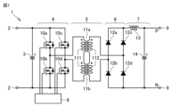
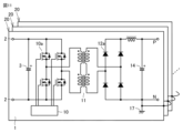
- FIG. 1 is a circuit diagram illustrating an example of a power supply circuit in a power conversion device according to an embodiment of the present disclosure.
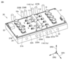
- 1 is a perspective view illustrating an example of a power unit and a cooler included in a power conversion device according to a first embodiment of the present disclosure.
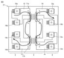
- 3 is a plan view showing an example of a wiring pattern formed on a substrate of the power conversion device shown in FIG. 2 and constituting a part of the power supply circuit shown in FIG. 1 .
- FIG. 3 is an exploded perspective view of a power unit of the power conversion device shown in FIG. 2 .
- FIG. 3 is a front view of a power unit of the power conversion device shown in FIG. 2 .
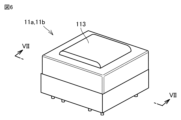
- 3 is a perspective view of a transformer included in a power unit of the power conversion device shown in FIG. 2.
- FIG. 7 is a cross-sectional view taken along line VII-VII in FIG. 6.
- 11 is a perspective view showing an example of a power unit included in a power conversion device according to a second embodiment.
- FIG. FIG. 9 is an exploded perspective view of a power unit of the power conversion device shown in FIG. 8 .
- FIG. 9 is a cross-sectional view of a power unit of the power conversion device shown in FIG. 8 .
- FIG. 11 is a circuit diagram showing an example of a plurality of power supply circuits in a power conversion device according to a third embodiment.
- FIG. 11 is a perspective view showing an example of a power unit and a cooler included in a power conversion device according to a third embodiment.
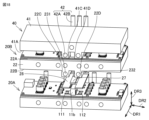
- FIG. 13 is an exploded perspective view of the power unit shown in FIG. 12.
- FIG. 13 is a side view for explaining the structure of the power unit shown in FIG. 12 and the connection structure between the power unit and a cooler.
- FIG. FIG. 13 is a cross-sectional view of the power unit shown in FIG. 12.
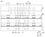
- FIG. 11 is a perspective view for explaining an example of a plurality of power units, a cooler, and a housing included in a power conversion device according to a third embodiment, the perspective view showing a state in which a side panel of the housing is open.
- 17 is a perspective view of the housing shown in FIG. 16, seen from a direction different from that of FIG. 16.
- FIG. FIG. 13 is an exploded perspective view for explaining an example of a power unit included in a power conversion device according to a fourth embodiment.
- FIG. 19 is a cross-sectional view of the power unit shown in FIG. 18.
- 13 is a cross-sectional view for explaining a first modified example of a power unit included in a power conversion device according to embodiment 4.
- FIG. FIG. 13 is an exploded perspective view for explaining a second modified example of the power unit included in the power conversion device according to embodiment 4.
- FIG. 22 is a cross-sectional view of the power unit shown in FIG. 21.
- FIG. 13 is a perspective view showing an example of a power unit included in a power conversion device according to embodiment 5.
- 24 is a cross-sectional view taken along line XXIV-XXIV in FIG. 23.
- 13 is a perspective view for explaining a modified example of a cooler included in a power conversion device according to embodiment 5.
- FIG. 13 is a perspective view showing an example of a power unit included in a power conversion device according to a sixth embodiment.
- FIG. 23 is an exploded perspective view for explaining a first modified example of a power unit included in a power conversion device according to embodiment 6.
- FIG. 23 is an exploded perspective view for explaining a second modified example of the power unit included in the power conversion device according to embodiment 6.
- FIG. 13 is a perspective view for explaining an example of a plurality of power units, a cooler, and a housing included in a power conversion device according to a sixth embodiment, the perspective view showing a state in which a side panel of the housing is open.
- a power conversion device includes a power supply circuit.
- the power supply circuit is, for example, a DC-DC converter.
- Fig. 1 shows an example of a circuit diagram of a DC-DC converter.
- the application of the power conversion device according to the embodiment of the present disclosure is not particularly limited, but is, for example, an electric vehicle.
- the DC-DC converter has a function of converting the input voltage of a lithium-ion battery, for example, between 100V and 300V, to a voltage between 12V and 15V, and outputting the converted voltage to charge a lead-acid battery.
- the DC-DC converter as a power supply circuit 1 comprises an input terminal 2, an input capacitor 3, an inverter circuit section 4, a transformer section 5, a rectifier circuit section 6, a smoothing circuit section 7, a control circuit section 8, and an output terminal 9.
- the inverter circuit section 4 and part of the transformer section 5 form the primary circuit, while the remaining part of the transformer section 5, the rectifier circuit section 6, and the smoothing circuit section 7 form the secondary circuit, which has an operating voltage different from that of the primary circuit.
- the inverter circuit section 4 is composed of four switching elements 10a, 10b, 10c, and 10d.
- the switching operations of the four switching elements 10a, 10b, 10c, and 10d are controlled by the control circuit section 8.
- Each of the switching elements 10a, 10b, 10c, and 10d is, for example, a power semiconductor element such as a MOS transistor (MOSFET: Metal Oxide Semiconductor Field Effect Transistor) or an insulated gate bipolar transistor (IGBT: Insulated Gate Bipolar Transistor).
- MOSFET Metal Oxide Semiconductor Field Effect Transistor
- IGBT Insulated Gate Bipolar Transistor
- the transformer section 5 is composed of two transformers 11a, 11b having a primary winding section 111 and a secondary winding section 112.
- the rectifier circuit section 6 is composed of four rectifier elements 12a, 12b, 12c, 12d.
- Each of the rectifier elements 12a, 12b, 12c, 12d is, for example, a power semiconductor element such as a diode, a MOS transistor, or a thyristor.
- the smoothing circuit section 7 is composed of a smoothing reactor 13 and a smoothing capacitor 14.
- the DC voltage input from the input terminal 2 is converted to an AC voltage by controlling the switching operation of each of the four switching elements 10a, 10b, 10c, and 10d in the inverter circuit section 4 by the control circuit section 8.
- the AC voltage converted in the inverter circuit section 4 is converted to an arbitrary voltage by the transformers 11a and 11b.
- the converted voltage is determined by the winding ratio between the primary winding section 111 and the secondary winding section 112 in the transformers 11a and 11b.
- the transformers 11a and 11b provide electrical insulation between the input terminal 2 and the output terminal 9.
- the AC voltage supplied from the transformer section 5 is converted back to DC voltage by four rectifier elements 12a, 12b, 12c, and 12d.
- the smoothing circuit section 7 the DC voltage converted by the rectifier circuit section 6 is smoothed by a smoothing reactor 13 and a smoothing capacitor 14. This stabilizes the output voltage output from the output terminal 9.
- One potential of the smoothing capacitor 14 is used as the reference potential of the power conversion device.
- the power conversion device which includes the power supply circuit 1, is provided with a heat dissipation unit that dissipates heat generated in at least one electronic component (first electronic component) among the switching elements 10a, 10b, 10c, and 10d, the rectifying elements 12a to 12d, the transformers 11a and 11b, and the smoothing reactor 13, and keeps the temperature of the first electronic component below its allowable temperature.
- the allowable temperature of each of the above-mentioned electronic components is, for example, 100°C or higher and 120°C or lower.
- the power conversion device includes a power unit 20 and a cooler 30.
- the power unit 20 includes a substrate 21, a first heat dissipation member 22, a plurality of first heat transport members 23, a thermally conductive member 24, and a positioning member 25.
- the substrate 21 is a wiring substrate that constitutes at least a part of the power supply circuit 1.
- the substrate 21 has a first surface 21A and a second surface 21B located on the opposite side to the first surface 21A.
- first direction DR1 The direction along the first surface 21A and perpendicular to the first direction
- second direction DR2 The direction along the first surface 21A and perpendicular to the first direction
- third direction DR3 The direction perpendicular to the first surface 21A will be referred to as the third direction DR3.
- Transformers 11a and 11b are mounted on the first surface 21A.
- Switching elements 10a, 10b, 10c, and 10d, rectifier elements 12a to 12d, and smoothing reactor 13 are mounted on the second surface 21B.
- an input capacitor 3 and a smoothing capacitor 14 are also mounted on the second surface 21B. From the viewpoint of smoothing the input voltage or output voltage, it is preferable that the capacitance of the input capacitor 3 and the smoothing capacitor 14 is several tens of uF or more.
- the input capacitor 3 and the smoothing capacitor 14 are, for example, electrolytic capacitors.
- the substrate 21 further has a wiring pattern that electrically connects the electronic components in the power supply circuit 1.
- the wiring pattern is formed, for example, on each of the first surface 21A and the second surface 21B.
- the substrate 21 is, for example, a glass composite substrate, a glass epoxy substrate, or a halogen-free substrate.
- the material that constitutes the wiring pattern may be any conductive material, for example, copper.
- the substrate 21 has a first wiring pattern 15 that electrically connects the inverter circuit section 4 and the primary winding section 111 of the transformers 11a, 11b of the transformer section 5, and a second wiring pattern 16 that electrically connects the rectifier circuit section 6 and the secondary winding section 112 of the transformers 11a, 11b.
- Each of the first wiring pattern 15 and the second wiring pattern 16 has, for example, a portion formed on the first surface 21A of the substrate 21, a portion formed on the second surface 21B, and a portion formed in a through hole penetrating between the first surface 21A and the second surface 21B and electrically connecting the above two portions.
- the switching elements 10a, 10b, 10c, and 10d included in the inverter circuit unit 4 are arranged on one side of the transformers 11a and 11b, and the rectifier elements 12a, 12b, 12c, and 12d included in the rectifier circuit unit 6 are arranged on the opposite side of the transformers 11a and 11b from the switching elements 10a, 10b, 10c, and 10d.
- the switching elements 10a, 10b, 10c, and 10d are arranged side by side in the first direction DR1.
- the rectifier elements 12a, 12b, 12c, and 12d are arranged side by side in the first direction DR1.
- the first wiring pattern 15 has, for example, a portion arranged between the switching elements 10a and 10b in the first direction DR1, and a portion arranged between the switching elements 10c and 10d in the first direction DR1.
- the second wiring pattern 16 has, for example, a portion that is arranged between the rectifying elements 12a and 12b in the first direction DR1, and a portion that is arranged between the rectifying elements 12c and 12d in the first direction DR1.
- each of the first wiring pattern 15 and the second wiring pattern 16 is designed to be wide so that the electrical resistance is low and excessive Joule heat is not generated during conduction.
- each of the first wiring pattern 15 and the second wiring pattern 16 is designed to be short in length and have a loop-shaped planar shape so that the parasitic inductance is low.
- each of the first wiring pattern 15 and the second wiring pattern 16 is designed so that the distance between them (insulation distance) satisfies various safety standards.
- the substrate 21 is positioned relative to the first heat dissipation member 22 by a number of positioning members 25.
- the first heat dissipation member 22 has a third surface 22A that is thermally connected to the first surface 21A, and a fourth surface 22B that is located on the opposite side to the third surface.
- the third surface 22A is, for example, parallel to the first surface 21A.
- the third surface 22A is thermally connected to the first surface 21A, for example, via a thermally conductive member 24.
- the third surface 22A may be in contact with the first surface 21A.
- the material constituting the first heat dissipation member 22 may be any material having high thermal conductivity, and includes, for example, aluminum (Al).
- the thermal conductivity of the first heat dissipation member 22 is 1.0 W/(m ⁇ K) or more, preferably 10.0 W/(m ⁇ K) or more, and more preferably 100.0 W/(m ⁇ K) or more.
- the first heat dissipation member 22 is, for example, an extruded material.
- a groove portion 221 is formed in the third surface 22A of the first heat dissipation member 22.
- the groove portion 221 has a pair of side surfaces 221A and a bottom surface 221B.
- the pair of side surfaces 221A are connected to the third surface 22A.
- Each of the pair of side surfaces 221A is, for example, perpendicular to the third surface 22A.
- the bottom surface 221B is, for example, parallel to the third surface 22A.
- a plurality of grooves 221 may be formed on the third surface 22A of the first heat dissipation member 22 at intervals in the second direction DR2.
- the depths of the plurality of grooves 221 may be equal to each other or may be different from each other.
- the grooves 221 are formed to extend, for example, from one end face to the other end face in the first direction DR1 of the first heat dissipation member 22.
- At least a portion of the transformers 11a and 11b is housed inside the groove 221.
- the entire transformers 11a and 11b and a portion of the thermally conductive member 24 are housed inside the groove 221.
- the pair of side surfaces 221A and the bottom surface 221B of the groove 221 are thermally connected to the transformers 11a and 11b via the thermally conductive member 24.
- the pair of side surfaces 221A are thermally connected, for example, to the outer peripheral surfaces of the cores of the transformers 11a and 11b.
- the bottom surface 221B is thermally connected, for example, to the spacer 113 of the transformers 11a and 11b.
- the first heat transport members are separate from the first heat dissipation member 22.
- the thermal conductivity of each of the first heat transport members 23 is higher than that of the first heat dissipation member 22.
- the thermal conductivity of each of the first heat transport members 23 is 10.0 W/(m ⁇ K) or more, preferably 100.0 W/(m ⁇ K) or more, and more preferably 1000.0 W/(m ⁇ K) or more.
- Each of the first heat transport members 23 includes a first portion 23A disposed inside the first heat dissipation member 22 and a second portion 23B connected to the first portion 23A and disposed outside the first heat dissipation member 22.
- Each of the first heat transport members 23 is provided to transport heat from the first portion 23A to the second portion 23B.
- At least a portion of the first portion 23A of each of the first heat transport members 23 extends parallel to the third surface 22A. At least a portion of the first portion 23A of each of the multiple first heat transport members 23 is disposed at intervals from one another in the second direction DR2. At least a portion of the first portion 23A of each of the multiple first heat transport members 23 extends parallel to one another, for example, along the first direction DR1. At least a portion of the second portion 23B of each of the multiple first heat transport members 23 extends parallel to one another, for example, along the third direction DR3. Each of the multiple first heat transport members 23 has a bent portion, for example, between the first portion 23A and the second portion 23B.
- Each of the multiple first heat transport members 23 is, for example, a heat pipe.
- the refrigerant vaporizes in the first portion 23A by absorbing heat from the first heat dissipation member 22, and liquefies in the second portion 23B by dissipating heat to the outside of the first heat dissipation member 22, so that the refrigerant circulates inside the heat pipe due to capillary action.
- the second portion 23B of each of the multiple first heat transport members 23 is thermally connected to the cooler 30.
- the cross-sectional shape perpendicular to the extension direction of each of the multiple first heat transfer members 23 is, for example, a circular shape. Note that the cross-sectional shape perpendicular to the extension direction of each of the multiple first heat transfer members 23 may be any shape, and may be, for example, an elliptical shape or a rectangular shape.
- each of the multiple first heat transport members 23 may have any configuration capable of transporting heat from the first heat dissipation member 22 to the outside of the first heat dissipation member 22.
- Each of the multiple first heat transport members 23 may be provided to form a flow path through which cooling water flows, or may include a graphite sheet made of graphite having a layered crystal structure.
- the multiple first heat transport members 23 include a first first heat transport member 231 (hereinafter also simply referred to as the first heat transport member 231), a second first heat transport member 232 (hereinafter also simply referred to as the first heat transport member 232), and a third first heat transport member 233 (hereinafter also simply referred to as the first heat transport member 233).
- the first portion 231A of the first heat transport member 231 extends along the side surface 221A of the groove portion 221. At least a part of the first portion 231A of the first heat transport member 231 is arranged so as to overlap the side surface 221A and the transformers 11a and 11b in a direction perpendicular to the side surface 221A (for example, the second direction DR2). At least a part of the first portion 231A of the first heat transport member 231 is arranged so as to overlap the third surface 22A, the substrate 21, and the switching elements 10a, 10b, 10c, and 10d in the third direction DR3.
- At least a part of the first portion 231A of the first heat transport member 231 is arranged so as to overlap the part of the first wiring pattern 15 that is arranged between the switching elements 10a and 10b in the third direction DR3 and the part that is arranged between the switching elements 10c and 10d in the first direction DR1.
- the center of the first portion 231A of the first heat transport member 231 is arranged so as to overlap the side surface 221A and the transformers 11a and 11b in a direction perpendicular to the side surface 221A, and is arranged so as to overlap the third surface 22A, the substrate 21, and each of the switching elements 10a, 10b, 10c, and 10d in the third direction DR3.
- the entire first portion 231A of the first heat transport member 231 is arranged so as to overlap the side surface 221A and the transformers 11a and 11b in a direction perpendicular to the side surface 221A, and is arranged so as to overlap the third surface 22A, the substrate 21, and each of the switching elements 10a, 10b, 10c, and 10d in the third direction DR3.
- the first portion 232A of the first heat transport member 232 extends along the side surface 221A of the groove portion 221. At least a portion of the first portion 232A of the first heat transport member 232 is arranged to overlap the side surface 221A and the transformers 11a and 11b in a direction perpendicular to the side surface 221A (e.g., the second direction DR2). At least a portion of the first portion 232A of the first heat transport member 232 is arranged to overlap each of the rectifying elements 12a, 12b, 12c, and 12d in the third direction DR3.
- first portion 232A of the first heat transport member 232 is arranged to overlap a portion of the second wiring pattern 16 that is arranged between the rectifying elements 12a and 12b in the first direction DR1 and a portion that is arranged between the rectifying elements 12c and 12d in the first direction DR1 in the third direction DR3.
- the first heat transfer member 231 and the first heat transfer member 232 are arranged to sandwich the groove portion 221 and the transformers 11a and 11b in the third direction DR3.
- the center of the first portion 232A of the first heat transport member 232 is arranged so as to overlap the side surface 221A and the transformers 11a and 11b in a direction perpendicular to the side surface 221A, and is arranged so as to overlap the third surface 22A, the substrate 21, and the rectifying elements 12a, 12b, 12c, and 12d in the third direction DR3.
- the entire first portion 232A of the first heat transport member 232 is arranged so as to overlap the side surface 221A and the transformers 11a and 11b in a direction perpendicular to the side surface 221A, and is arranged so as to overlap the third surface 22A, the substrate 21, and the rectifying elements 12a, 12b, 12c, and 12d in the third direction DR3.
- the first portion 233A of the first heat transport member 233 extends along the bottom surface 221B of the groove portion 221. At least a portion of the first portion 232A of the first heat transport member 232 is arranged so as to overlap with each of the bottom surface 221B, the transformer 11a, and the transformer 11b in a direction perpendicular to the bottom surface 221B (e.g., the third direction DR3).
- the center of the first portion 233A of the first heat transport member 233 is arranged so as to overlap with the bottom surface 221B, the transformer 11a, and the transformer 11b in a direction perpendicular to the bottom surface 221B. More preferably, the entire first portion 233A of the first heat transport member 233 is arranged so as to overlap with the bottom surface 221B, the transformer 11a, and the transformer 11b in a direction perpendicular to the bottom surface 221B.
- the first portion 231A of the first heat transport member 231, the first portion 232A of the first heat transport member 232, and the first portion 233A of the first heat transport member 233 are each thermally connected to the transformers 11a and 11b via the first heat dissipation member 22 and the thermally conductive member 24.
- the first portion 231A of the first heat transport member 231, the first portion 232A of the first heat transport member 232, and the first portion 233A of the first heat transport member 233 are each thermally connected to the transformers 11a and 11b without going through the substrate 21.
- the first portion 232A of the first heat transport member 232 is thermally connected to each of the switching elements 10a, 10b, 10c, and 10d via the first heat dissipation member 22, the substrate 21, and the thermally conductive member 24.
- the first portion 233A of the first heat transport member 233 is thermally connected to each of the rectifying elements 12a to 12d via the first heat dissipation member 22 and the thermally conductive member 24.
- the thermally conductive member 24 has high thermal conductivity and electrical insulation.
- the thermal conductivity of the thermally conductive member 24 is preferably 0.1 W/(m ⁇ K) or more, more preferably 1.0 W/(m ⁇ K) or more, and more preferably 10.0 W/(m ⁇ K) or more.
- the thermally conductive member 24 includes at least one selected from the group consisting of, for example, thermally conductive grease, a thermally conductive sheet, a thermally conductive adhesive, and a thermally conductive gap filler.
- the gap filler may be, for example, a one-liquid non-mixing type gap filler or a two-liquid mixing type gap filler.
- the plurality of positioning members 25 position the substrate 21 and the first heat dissipation member 22, which are stacked with the thermally conductive member 24 in between.
- the plurality of positioning members 25 includes, for example, a spacer portion that is stretched between the substrate 21 and the first heat dissipation member 22, and a fixing member such as a screw that fixes each of the substrate 21 and the first heat dissipation member 22 to the spacer portion.
- the plurality of positioning members 25 maintain the dimension (thickness) of the thermally conductive member 24 in the third direction DR3 constant regardless of the position in the first direction DR1 and the second direction DR2.
- the thermally conductive member 24 does not have a region with locally low insulation performance (voltage resistance) and heat dissipation performance, so that the deterioration of the reliability of the power conversion device can be suppressed.
- the thickness of the thermally conductive member 24 is non-uniform, in a thick-walled region where the thickness of the thermally conductive member 24 is locally thick, the heat dissipation performance is lower than in a thin-walled region where the thickness of the thermally conductive member 24 is thinner than the thick-walled region, and therefore hot spots are likely to be formed. Therefore, there is a risk of cracks occurring in the soldered portions of the substrate 21 located on the thick regions of the thermally conductive member 24.
- the thickness of the thermally conductive member 24 is uniform, so the above-mentioned cracks are less likely to form.
- the multiple positioning members 25 include, for example, a first positioning member 25 that is placed between the third surface 22A of the first heat dissipation member 22 and the substrate 21, and a second positioning member 25 that is placed between the bottom surface of the groove portion 221 of the first heat dissipation member 22 and the substrate 21.
- the material that constitutes each of the multiple positioning members 25 is not particularly limited, and may include at least one of metal and resin.
- the cooler 30 is provided to cool the second portion 23B of each of the multiple first heat transport members 23.
- the cooler 30 may have any structure capable of cooling the second portion 23B of each of the multiple first heat transport members 23.
- the cooler 30 includes, for example, at least one cooling body 31 thermally connected to the second portions 231B, 232B, 233B (see FIG. 5) of each of the multiple first heat transport members 231, 232, 233, and at least one fan 32 that blows air to the at least one cooling body 31.
- the cooling body 31 is forced air-cooled by the fan 32.
- the blowing direction of the fan 32 is, for example, along the second direction DR2.
- the cooling body 31 may have an air tunnel and fins exposed within the air tunnel.
- the cooler 30 is arranged side by side with the substrate 21 and the first heat dissipation member 22 in the first direction DR1.
- One of the transformers 11a, 11b is farther from the cooler 30 than the other.
- the transformer 11b is farther from the cooler 30 than the transformer 11a.
- Each of the switching elements 10a, 10b, 10c, and 10d is arranged side by side from the cooler 30 side in the first direction DR1.
- Each of the rectifying elements 12a, 12b, 12c, and 12d is arranged side by side from the cooler 30 side in the first direction DR1.
- the configuration of the transformers 11a and 11b is not particularly limited. As shown in Figs. 6 and 7, the transformers 11a and 11b have a core (EI core) that is a combination of an E-type core 114 and an I-type core 115, for example.
- the transformers 11a and 11b may also have a combination of two U-type cores, a combination of two E-type cores, or a combination of a T-type core and a U-type core.
- the secondary winding section 112 is wound around the primary winding section 111, for example, so as to surround the primary winding section 111.
- the transformers 11a and 11b may further include a U-shaped spacer 113 inserted between the primary winding section 111 and the secondary winding section 112.
- the spacer 113 is exposed, for example, on the side opposite the terminal electrically connected to the substrate 21 in the transformers 11a and 11b.
- the exposed surface of the spacer 113 may be thermally connected to the bottom surface 221B of the groove section 221 via the thermally conductive member 24.
- the cores of each of the transformers 11a and 11b are, for example, ferrite cores such as manganese zinc (Mn-Zn) ferrite cores or nickel zinc (Ni-Zn) ferrite cores, amorphous cores, or iron dust cores.
- ferrite cores such as manganese zinc (Mn-Zn) ferrite cores or nickel zinc (Ni-Zn) ferrite cores, amorphous cores, or iron dust cores.
- the power unit 20 may further include a first heat transport member having a first portion thermally connected to the input capacitor 3, and a first heat transport member having a first portion thermally connected to the smoothing capacitor 14.
- the power converter according to the first embodiment includes a first heat transfer member 231 whose first portion 231A is thermally connected to each of the transformers 11a and 11b (first electronic components) via the first heat dissipation member 22. Therefore, the heat generated in each of the transformers 11a and 11b is quickly transferred to the second portion 231B of the first heat transfer member 231 through the first heat dissipation member 22 and the first portion 231A of the first heat transfer member 231, and can be released from the second portion 231B to the outside of the power converter by the cooler 30 or the like.
- the power conversion device can achieve both miniaturization and high output, as compared with the conventional power conversion device described above.
- the transformers 11a and 11b are arranged side by side in the first direction DR1. At least a portion of the first portion 231A of the first heat transport member 231 extends along the first direction DR1 and is arranged so as to overlap with the first heat dissipation member 22 and each of the transformers 11a and 11b in the third direction DR3 perpendicular to the first surface.
- the heat dissipation performance for each of the transformers 11a and 11b is improved compared to a power conversion device not having the above configuration.
- the arrangement of electronic components that generate a large amount of heat is limited, so the wiring path of the circuit including the electronic components becomes long, and parasitic inductance increases, which may cause high switching surges.
- the conventional power conversion device described above requires high-voltage semiconductor elements and noise countermeasures, making it difficult to reduce the size and manufacturing costs.
- the arrangement of electronic components that generate a large amount of heat is not limited by the distance from the cooler 30. Therefore, the transformers 11a and 11b, the switching elements 10a, 10b, 10c, and 10d, and the rectifier elements 12a, 12b, 12c, and 12d can be arranged as shown in FIG. 3.
- the power conversion device according to embodiment 1 can suppress an increase in parasitic inductance and the generation of noise, and can also achieve size reduction and reduction in manufacturing costs.
- the power unit 20 and the cooler 30 are arranged side by side in the first direction DR1, so the dimension of the power conversion device in the third direction DR3 can be reduced (reduced in height).
- the cooling body 31 and the fan 32 are arranged side by side in the second direction DR2, so the dimension of the cooler 30 in the third direction DR3 can be reduced compared to when the cooling body 31 and the fan 32 are arranged side by side in the third direction DR3, and as a result, the dimension of the power conversion device in the third direction DR3 can be reduced.
- a groove 221 is formed in the third surface 22A of the first heat dissipation member 22, and a pair of side surfaces 221A of the groove 221 are thermally connected to the side surfaces of the transformers 11a and 11b.
- At least a part of the first portion 231A of the first heat transport member 231 extends along the side surface 221A and is arranged so as to overlap each of the transformers 11a and 11b and the side surface 221A in a direction perpendicular to the side surface 221A. Therefore, the heat generated in the transformers 11a and 11b can be rapidly transferred to the first portion 231A of the first heat transport member 231 via the side surface and the side surface 221A of the groove 221 of the first heat dissipation member 22.
- At least a portion of the first portion 231A of the first heat transport member 231 is arranged to overlap each of the switching elements 10a, 10b, 10c, and 10d (second electronic components) in the third direction DR3, and is thermally connected to each of the switching elements 10a, 10b, 10c, and 10d via the first heat dissipation member 22 and the substrate 21.
- the heat dissipation performance for each of the transformers 11a, 11b and the switching elements 10a, 10b, 10c, and 10d is improved compared to a power conversion device not having the above configuration.
- a power conversion device having the above configuration can be made smaller than a power conversion device in which the first heat transport member, in which at least a portion of the first portion is arranged to overlap each of the switching elements 10a, 10b, 10c, and 10d in the third direction DR3, is provided separately from the first heat transport member, in which at least a portion of the first portion is arranged to overlap each of the transformers 11a and 11b.
- the first portion 232A of the first heat transport member 232 is arranged so as to overlap each of the transformers 11a, 11b and the side surface 221A in a direction perpendicular to the side surface 221A, and to overlap each of the rectifying elements 12a, 12b, 12c, and 12d in the third direction DR3.
- the first portion 232A of the first heat transport member 232 is thermally connected to each of the transformers 11a, 11b via the first heat dissipation member 22, and is thermally connected to each of the rectifying elements 12a, 12b, 12c, and 12d via the first heat dissipation member 22 and the substrate 21.
- a power conversion device having the above configuration the heat dissipation performance for each of the transformers 11a, 11b and the rectifying elements 12a, 12b, 12c, and 12d is improved compared to a power conversion device not having the above configuration. Furthermore, a power conversion device having the above configuration can be made smaller than a power conversion device in which the first heat transport member, at least a portion of which is arranged to overlap each of the rectifier elements 12a, 12b, 12c, and 12d in the third direction DR3, is provided separately from the first heat transport member, at least a portion of which is arranged to overlap each of the transformers 11a and 11b.
- the bottom surface 221B of the groove portion 221 is thermally connected to the transformers 11a and 11b. At least a part of the first portion 233A of the first heat transfer member 233 extends along the bottom surface 221B, and is arranged so as to overlap with each of the transformers 11a and 11b and the bottom surface 221B in a direction perpendicular to the bottom surface 221B. In the power conversion device having the above configuration, the heat dissipation performance for each of the transformers 11a and 11b is improved compared to a power conversion device not having the first heat transfer member 233.
- At least a portion of the first portion 231A of the first heat transport member 231 is arranged to overlap in the third direction DR3 with a portion of the first wiring pattern 15 that electrically connects the primary winding portion 111 of the transformers 11a and 11b.
- at least a portion of the first portion 232A of the first heat transport member 232 is arranged to overlap in the third direction DR3 with a portion of the second wiring pattern 16 that electrically connects the rectifier circuit portion 6 with the secondary winding portion 112 of the transformers 11a and 11b.
- the Joule heat generated in the first wiring pattern 15 and the second wiring pattern 16 can also be rapidly transferred to the first portions 231A and 232A of the first heat transport members 231 and 232 via the first heat dissipation member 22.
- the heat dissipation performance for the first wiring pattern 15 and the second wiring pattern 16 is improved to the same level as the heat dissipation performance for the transformers 11a, 11b, etc.
- the power converters shown in Figures 2 to 5 include a plurality of first heat transport members thermally connected to each of the switching elements 10a, 10b, 10c, and 10d, the rectifying elements 12a to 12d, and the transformers 11a and 11b, but are not limited thereto.
- the power converter according to the embodiment of the present disclosure may include at least one first heat transport member thermally connected to at least one electronic component that generates a relatively large amount of heat.
- the first electronic component thermally connected to the first portion of at least one first heat transport member may be at least one of the transformers 11a and 11b, the switching elements 10a, 10b, 10c, and 10d, the rectifying elements 12a to 12d, and the smoothing reactor 13.
- the arrangement of the electronic components and the arrangement of the at least one first heat transport member 23 are not particularly limited, so long as the at least one first heat transport member is thermally connected to at least one electronic component that generates a relatively large amount of heat.
- the at least one first heat transport member 23 may be thermally connected to various types of electronic components.
- each of a plurality of electronic components of the same type may be thermally connected to a different first heat transport member.
- one first heat transport member 23 may be thermally connected to the transformer 11a and the switching element 10a, and another first heat transport member 23 may be thermally connected to the transformer 11b and the switching element 10b.
- At least one first heat transport member may be thermally connected to an electronic component that generates a relatively small amount of heat.
- the first heat transport member 231 may be thermally connected to the input capacitor 3 in addition to the switching elements 10a, 10b, 10c, and 10d, the transformers 11a and 11b, and the first wiring pattern 15.
- the electronic component that generates a relatively large amount of heat is thermally connected to a region of the first part of the first heat transport member that is closer to the second part than the electronic component that generates a relatively small amount of heat.
- the first portion 231A of the first heat transfer member 231 extends linearly along the first direction DR1, but is not limited to this.
- the first portion 231A may have, for example, a bent shape, such as a U-shape, an L-shape, or a serpentine shape.
- the transformer unit 5 of the power supply circuit 1 includes two transformers 11a, 11b, but the number of transformers included in the transformer unit 5 is not limited to two.
- the number of transformers included in the transformer unit 5 may be one.
- one transformer has a longitudinal direction and a lateral direction when viewed from the third direction DR3, the longitudinal direction of the one transformer is arranged along the first direction DR1, and the lateral direction of the one transformer is arranged along the second direction DR2.
- This type of power conversion device can also achieve both compactness and high output compared to the conventional power conversion device described above.
- the groove portion 221 only needs to be able to accommodate at least a portion of each of the transformers 11a and 11b.
- the groove portion 221 only needs to be formed in at least a portion of the area between one end face and the other end face in the first direction DR1 of the first heat dissipation member 22.
- Embodiment 2 8 to 10, unless otherwise specified, the power conversion device according to the second embodiment has the same configuration and the same action and effect as those of the first embodiment. Therefore, the same components as those of the first embodiment are denoted by the same reference numerals, and the description thereof will not be repeated.
- At least a portion of the transformers 11a and 11b are arranged on the second surface 21B together with the switching elements 10a, 10b, 10c, and 10d and the rectifying elements 12a, 12b, 12c, and 12d.
- Each of the transformers 11a and 11b has a portion disposed on the first surface 21A, a portion disposed on the second surface 21B, and a portion inserted into a through hole passing between the first surface 21A and the second surface 21B.
- Each of the transformers 11a and 11b has a structure that combines, for example, an E-type core and an I-type core.
- a part of the E-type core is arranged on the first surface 21A
- the I-type core is arranged on the second surface 21B.
- the legs of the E-type core are inserted into through holes in the substrate 21 that are formed to penetrate between the first surface 21A and the second surface 21B.
- the transformer 11b has a portion 11b1 arranged on the first surface 21A and a portion 11b2 arranged on the second surface 21B.
- the primary winding portion 111 and the secondary winding portion 112 of each of the transformers 11a and 11b are formed as wiring patterns on, for example, the second surface 21B of the substrate 21.
- a groove 221 is formed on the third surface 22A of the first heat dissipation member 22 to accommodate the portion of each of the transformers 11a, 11b that is disposed on the first surface 21A.
- the groove 221 is formed, for example, only in a partial area between one end face and the other end face of the first heat dissipation member 22 in the first direction DR1.
- the groove 221 may be formed to extend from one end face to the other end face of the first heat dissipation member 22 in the first direction DR1.
- each of the transformers 11a and 11b that is disposed on the first surface 21A is thermally connected to the inner circumferential surface of the groove portion 221 via the thermally conductive member 26.
- the thermally conductive member 26 is configured as a member separate from the thermally conductive member 24, for example.
- the thermally conductive member 26 may be configured integrally with the thermally conductive member 24 as the same member.
- the thermally conductive member 26 has high thermal conductivity and electrical insulation.
- the thermal conductivity of the thermally conductive member 26 is preferably 0.1 W/(m ⁇ K) or more, more preferably 1.0 W/(m ⁇ K) or more, and more preferably 10.0 W/(m ⁇ K) or more.
- the thermally conductive member 26 includes at least one selected from the group consisting of thermally conductive grease, a thermally conductive sheet, a thermally conductive adhesive, and a thermally conductive gap filler.
- the gap filler may be, for example, a one-liquid non-mixing type gap filler or a two-liquid mixing type gap filler.
- the thermally conductive member 26 is made of a thermally conductive gap filler
- the thermally conductive gap filler then hardens, bonding the transformers 11a and 11b to the first heat dissipation member 22 with the thermally conductive member 26, and the transformers 11a and 11b are thermally connected to the first heat dissipation member 22 via the thermally conductive member 26.
- the power unit 20 includes a plurality of first heat transport members 23.
- the plurality of first heat transport members 23 include a fourth first heat transport member 234 (hereinafter also simply referred to as the first heat transport member 234), a fifth first heat transport member 235 (hereinafter also simply referred to as the first heat transport member 235), a sixth first heat transport member 236 (hereinafter also simply referred to as the first heat transport member 236), and a sixth first heat transport member 237 (hereinafter also simply referred to as the first heat transport member 237).
- the first portion 234A of the first heat transport member 234 extends along the side of the groove portion 221. At least a portion of the first portion 234A of the first heat transport member 234 is arranged so as to overlap the side and the transformers 11a, 11b in a direction perpendicular to the side (e.g., the second direction DR2). At least a portion of the first portion 234A of the first heat transport member 234 is arranged so as to overlap each of the third surface 22A, the substrate 21, and the primary winding portion 111 in the third direction DR3.
- the center of the first portion 234A of the first heat transport member 234 is arranged so as to overlap the side surface and the transformers 11a and 11b in a direction perpendicular to the side surface, and is arranged so as to overlap the third surface 22A, the substrate 21, and the primary winding section 111 in the third direction DR3. More preferably, the entire first portion 234A of the first heat transport member 234 is arranged so as to overlap the side surface and the transformers 11a and 11b in a direction perpendicular to the side surface, and is arranged so as to overlap the third surface 22A, the substrate 21, and the primary winding section 111 in the third direction DR3.
- At least a portion of the first portion 235A of the first heat transfer member 235 is arranged to overlap with the third surface 22A, the substrate 21, and each of the switching elements 10a, 10b, 10c, and 10d in the third direction DR3.
- the center of the first portion 235A of the first heat transport member 235 is arranged to overlap with the third surface 22A, the substrate 21, and each of the switching elements 10a, 10b, 10c, and 10d in the third direction DR3. More preferably, the entire first portion 235A of the first heat transport member 235 is arranged to overlap with the third surface 22A, the substrate 21, and each of the switching elements 10a, 10b, 10c, and 10d in the third direction DR3.
- Each of the first heat transfer members 236 and 237 has a symmetrical relationship with each of the first heat transfer members 234 and 235 with respect to the groove portion 221, for example.
- the first portion 236A of the first heat transport member 236 extends along the side of the groove portion 221. At least a portion of the first portion 236A of the first heat transport member 236 is arranged to overlap the side and the transformers 11a, 11b in a direction perpendicular to the side (e.g., the second direction DR2). At least a portion of the first portion 236A of the first heat transport member 236 is arranged to overlap each of the third surface 22A, the substrate 21, and the secondary winding portion 112 in the third direction DR3.
- the center of the first portion 236A of the first heat transport member 236 is arranged so as to overlap the side surface and the transformers 11a and 11b in a direction perpendicular to the side surface, and is arranged so as to overlap the third surface 22A, the substrate 21, and the secondary winding section 112 in the third direction DR3. More preferably, the entire first portion 236A of the first heat transport member 236 is arranged so as to overlap the side surface and the transformers 11a and 11b in a direction perpendicular to the side surface, and is arranged so as to overlap the third surface 22A, the substrate 21, and the secondary winding section 112 in the third direction DR3.
- At least a portion of the first portion 237A of the first heat transport member 237 is arranged to overlap with the third surface 22A, the substrate 21, and each of the rectifying elements 12a, 12b, 12c, and 12d in the third direction DR3.
- the center of the first portion 237A of the first heat transport member 237 is arranged to overlap with the third surface 22A, the substrate 21, and each of the rectifying elements 12a, 12b, 12c, and 12d in the third direction DR3. More preferably, the entire first portion 237A of the first heat transport member 237 is arranged to overlap with the third surface 22A, the substrate 21, and each of the rectifying elements 12a, 12b, 12c, and 12d in the third direction DR3.
- the power conversion device according to the second embodiment also achieves the same effects as the power conversion device according to the first embodiment.
- heat generated in the primary winding section 111 and the secondary winding section 112 of the transformers 11a and 11b is quickly transferred to the first parts 234A and 236A of the first heat transport members 234 and 236 via the first heat dissipation member 22, thereby improving the heat dissipation performance of the transformers 11a and 11b.
- each of the switching elements 10a, 10b, 10c, and 10d is thermally connected to the first heat transport member 235 via the first heat dissipation member 22, and is also thermally connected to the first heat transport member 234 via the primary winding section 111 and the first heat dissipation member 22.
- each of the rectifying elements 12a, 12b, 12c, and 12d is thermally connected to the first heat transport member 237 via the first heat dissipation member 22, and is also thermally connected to the first heat transport member 236 via the secondary winding section 112 and the first heat dissipation member 22. Therefore, in the power conversion device according to the second embodiment, the heat dissipation performance of the switching elements 10a, 10b, 10c, and 10d and the rectifying elements 12a, 12b, 12c, and 12d is also improved.
- the entire transformers 11a and 11b may be disposed on the first surface 21 A.
- the third surface 22A of the first heat dissipation member 22 does not necessarily have to have a groove.
- the above-mentioned wiring pattern of the substrate 21 may be formed only on the second surface 21B.
- the substrate 21 may be a metal base substrate in which a metal base body, an insulating layer, and a wiring layer are laminated in the order described.
- the first surface 21A is the surface of the metal base body
- the second surface 21B is the surface of the wiring layer.
- the thermal conductivity of the metal base body is preferably 1.0 W/(m ⁇ K) or more, more preferably 10.0 W/(m ⁇ K) or more, and more preferably 100.0 W/(m ⁇ K) or more.
- the metal material constituting the metal base body is, for example, copper (Cu), iron (Fe), aluminum (Al), or an alloy thereof.
- the primary winding section 111 and the secondary winding section 112 of each of the transformers 11a and 11b may be a laminated bus bar mounted on the substrate 21.
- Such primary winding section 111 and secondary winding section 112 may be formed by laminating a laminate of an insulating film sheet and a metal conductor.
- the insulating film sheet includes at least one selected from the group consisting of a film made of polyethylene terephthalate (PET: Poly Ethylene Terephthalate), a film made of polyimide (PI: Poly Imide), and a sheet made of aramid (fully aromatic polyamide) fibers.
- PET Poly Ethylene Terephthalate
- PI Poly Imide
- aramid fully aromatic polyamide
- the power unit 20 may include a first heat transfer member 233, similar to the power unit 20.
- the power conversion device according to the second embodiment can also be modified in the same manner as the modified example of the power conversion device according to the first embodiment described above.
- the power conversion device according to the third embodiment has the same configuration and the same action and effect as those of the first or second embodiment. Therefore, the same components as those of the first or second embodiment are denoted by the same reference numerals, and the description thereof will not be repeated.
- the power conversion device includes a plurality of power units 20.
- Each of the plurality of power units 20 has a configuration equivalent to that of the power unit 20 of the second embodiment, for example.
- Each of the plurality of power units 20 includes a power supply circuit 1.
- the smoothing circuit section 7 of each of the plurality of power supply circuits 1 has a ground terminal 17.
- the first heat dissipation member 22 is electrically connected to the ground terminal 17.
- the multiple power units 20 are stacked in the third direction DR3.
- the multiple power units 20 include a first power unit 20A and a second power unit 20B.
- the second surface 21B of the substrate 21 of the first power unit 20A faces the fourth surface 22B of the first heat dissipation member 22 of the second power unit 20B.
- the fourth surface 22B of the first heat dissipation member 22 of the second power unit 20B is thermally connected to the transformers 11a and 11b of the first power unit 20A.
- the fourth surface 22B of the first heat dissipation member 22 of the second power unit 20B is thermally connected to the top surfaces of the transformers 11a and 11b of the first power unit 20A, for example, via a thermally conductive member 27.
- the thermally conductive member 27 has high thermal conductivity and electrical insulation.
- the thermal conductivity of the thermally conductive member 27 is preferably 0.1 W/(m ⁇ K) or more, more preferably 1.0 W/(m ⁇ K) or more, and more preferably 10.0 W/(m ⁇ K) or more.
- the thermally conductive member 27 includes at least one selected from the group consisting of, for example, thermally conductive grease, a thermally conductive sheet, a thermally conductive adhesive, and a thermally conductive gap filler.
- the gap filler may be, for example, a one-liquid non-mixing type gap filler or a two-liquid mixing type gap filler.
- the fourth surface 22B of the first heat dissipation member 22 of the second power unit 20B is disposed at a distance from, for example, the top surfaces of the switching elements 10a, 10b, 10c, 10d and the rectifying elements 12a, 12b, 12c, 12d of the first power unit 20A.
- the fourth surface 22B of the first heat dissipation member 22 of the second power unit 20B may be thermally connected to the top surfaces of the switching elements 10a, 10b, 10c, 10d and the rectifying elements 12a, 12b, 12c, 12d of the first power unit 20A via a thermally conductive member.
- the power conversion device further includes a heat dissipation unit 40.
- the multiple power units 20 and heat dissipation units 40 are stacked and arranged at intervals in the third direction DR3.
- the heat dissipation unit 40 is arranged on the opposite side of the second power unit 20B from the first power unit 20A.
- the heat dissipation unit 40 includes a second heat dissipation member 41 and a plurality of second heat transfer members 42.
- the second heat dissipation member 41 has, for example, a configuration similar to that of the first heat dissipation member 22.
- the second heat transfer member 42 has, for example, a configuration similar to that of the first heat transfer member 41.
- the second heat dissipation member 41 is thermally connected to the second power unit 20B.
- the second heat dissipation member 41 has a fifth surface 41A that faces the second surface 21B of the substrate 21 of the second power unit 20B.
- the fifth surface 41A of the second heat dissipation member 41 is thermally connected to the transformers 11a, 11b of the second power unit 20B.
- the fifth surface 41A is, for example, perpendicular to the third direction DR3.
- the second heat transport members are separate from the second heat dissipation member 41.
- the thermal conductivity of each of the second heat transport members 42 is higher than the thermal conductivity of the second heat dissipation member 41.
- Each of the second heat transport members 42 includes a third portion 42A disposed inside the second heat dissipation member 41 and a fourth portion 42B connected to the third portion 42A and disposed outside the second heat dissipation member 41.
- Each of the second heat transport members 42 is configured to transport heat from the third portion 42A to the fourth portion 42B.
- At least a portion of the third portion 42A of each of the multiple second heat transport members 42 extends parallel to the fifth surface 41A. At least a portion of the third portion 42A of each of the multiple second heat transport members 42 are arranged at intervals from each other in the second direction DR2. At least a portion of the third portion 42A of each of the multiple second heat transport members 42 extends parallel to each other, for example, along the first direction DR1.
- Each of the multiple second heat transport members 42 has a configuration equivalent to, for example, each of the multiple first heat transport members 23.
- Each of the multiple second heat transport members 42 is, for example, a heat pipe.
- the second portions 23B of the first heat transfer members 23 of each of the power units 20 and the fourth portions 42B of the second heat transfer members 42 of the heat dissipation unit 40 are thermally connected to, for example, one cooling body 31.
- one cooler 30 is provided to cool the power units 20 and the heat dissipation units 40.
- the cooler 30 includes, for example, one cooling body 31 and multiple fans 32.
- the multiple fans 32 are arranged, for example, next to each other in the third direction DR3. As described above, it is sufficient that the cooler 30 includes at least one fan 32.
- the power conversion device further includes a housing 50 that houses the multiple power units 20 and the cooling body 31 of the cooler 30.
- the fan 32 of the cooler 30 is arranged, for example, outside the housing 50.
- the multiple power units 20 and the cooler 30 are arranged inside the housing 50, for example, so that the first direction DR1 is aligned along the vertical direction.
- Each of the multiple power units 20 is arranged next to each other at intervals in the third direction DR3.
- the multiple power units 20 are arranged, for example, below the cooler 30.
- the housing 50 includes a number of plates that separate the interior and exterior of the housing 50.
- the multiple plates include a front plate 51, a rear plate 52, side plates 53, a top plate 54, and a bottom plate 55.
- the front plate 51 and the rear plate 52 are spaced apart from each other in the second direction DR2.
- the pair of side plates 53 are spaced apart from each other in the third direction DR3.
- the top plate 54 and the bottom plate 55 are spaced apart from each other in the first direction DR1.
- the fan 32 is fixed above the front plate 51.
- An opening (not shown) is formed above the front plate 51 through which the air sent from the fan 32 to the cooling body 31 flows from the outside of the housing 50 to the inside.
- An opening 57 (see FIG. 17) is formed above the rear plate 52 through which the air that has flowed around the cooling body 31 flows from the inside of the housing 50 to the outside.
- a pair of intake and exhaust ports 56 are formed in each of the front plate 51 and the rear plate 52 to communicate between the inside and outside of the housing 50.
- a portion of each of the multiple power units 20 is disposed between the pair of intake and exhaust ports 56 in the second direction DR2.
- the pair of intake and exhaust ports 56 are disposed so as to sandwich a portion of each of the multiple power units 20 in the second direction DR2.
- An air flow path can be formed between the pair of intake and exhaust ports 56 between two power units 20 adjacent to each other in the third direction DR3.
- the intake and exhaust port 56 is formed below the opening.
- the number and shape of the intake and exhaust ports 56 are not particularly limited.
- a fan may be provided to create an air flow through a pair of intake and exhaust ports 56.
- the power conversion device according to the third embodiment also achieves the same effects as the power conversion device according to the first embodiment.
- the transformers 11a and 11b of the first power unit 20A are thermally connected not only to the first heat dissipation member 22 and the first heat transport member 23 of the first power unit 20A, but also to the first heat dissipation member 22 and the first heat transport member 23 of the second power unit 20B. Furthermore, the transformers 11a and 11b of the second power unit 20B are thermally connected not only to the first heat dissipation member 22 and the first heat transport member 23 of the second power unit 20B, but also to the second heat dissipation member 41 and the second heat transport member 42 of the heat dissipation unit 40. Therefore, in the power conversion device according to the third embodiment, the cooling performance for the transformers 11a and 11b included in the multiple power units 20 is high.
- the potential of the first heat dissipation member 22 of each of the multiple power units 20 is set to the same potential as the earth, so that the radiated noise from each power supply circuit 1 can be blocked by each first heat dissipation member 22.
- the effect of the radiated noise on each of the multiple power supply circuits 1 is suppressed, making malfunctions less likely to occur.
- wind tunnels are formed between the first power unit 20A and the second power unit 20B, and between the second power unit 20B and the heat dissipation unit 40.
- the electronic components mounted on the second surface 21B of each of the first power unit 20A and the second power unit 20B face each wind tunnel.
- convection can be promoted by the chimney effect. Therefore, air that flows into the inside of the housing 50 from one of the intake and exhaust ports 56 passes through each wind tunnel, is heated by heat exchange with each electronic component, and can be discharged to the outside of the housing 50 from the other intake and exhaust port 56.
- each electronic component can be air-cooled.
- Such air cooling is particularly effective for dissipating heat from electronic components that are not thermally connected to the first heat transfer member 23 and the second heat transfer member 42.
- electronic components other than the transformers 11a and 11b may be thermally connected to the first heat dissipation member 22 of another power unit 20 or the second heat dissipation member 41 of the heat dissipation unit 40 different from the power unit 20 in which the electronic components are mounted.
- the transformers 11a and 11b, the switching elements 10a, 10b, 10c, and 10d, and the rectifying elements 12a, 12b, 12c, and 12d may be thermally connected to the first heat dissipation member 22 of the other power unit 20 or the second heat dissipation member 41 of the heat dissipation unit 40.
- the power conversion device according to the third embodiment can be modified in the same manner as the modifications of the first and second embodiments described above.
- the heat dissipation unit 40 may be provided in the power conversion device according to the first or second embodiment.
- the power conversion device according to the fourth embodiment has the same configuration and the same action and effect as those of the third embodiment. Therefore, the same components as those of the third embodiment are denoted by the same reference numerals and will not be described repeatedly.
- the first heat dissipation member 22 of the second power unit 20B has a first protrusion 22C and a second protrusion 22D that protrude from the fourth surface 22B toward the second surface 21B of the first power unit 20A.
- Each of the first protrusion 22C and the second protrusion 22D is arranged in the second direction DR2 so as to overlap with a portion of the transformers 11a and 11b of the first power unit 20A that is arranged on the second surface 21B.
- the first protrusion 22C and the second protrusion 22D are arranged in the second direction DR2 so as to sandwich a portion of the transformers 11a and 11b of the first power unit 20A that is arranged on the second surface 21B.
- each of the first protrusion 22C and the second protrusion 22D is thermally connected to the second surface 21B of the substrate 21 of the first power unit 20A.
- the top surface of the first protrusion 22C is thermally connected to the primary winding section 111 (third electronic component) mounted on the second surface 21B of the substrate 21 of the first power unit 20A, for example, via a thermally conductive member 28.
- the top surface of the second protrusion 22D is thermally connected to the secondary winding section 112 (third electronic component) mounted on the second surface 21B of the substrate 21 of the first power unit 20A, for example, via a thermally conductive member 28.
- the thermally conductive member 28 has high thermal conductivity and electrical insulation.
- the thermal conductivity of the thermally conductive member 28 is preferably 0.1 W/(m ⁇ K) or more, more preferably 1.0 W/(m ⁇ K) or more, and more preferably 10.0 W/(m ⁇ K) or more.
- the thermally conductive member 28 includes at least one selected from the group consisting of thermally conductive grease, a thermally conductive sheet, a thermally conductive adhesive, and a thermally conductive gap filler.
- the gap filler may be, for example, a one-liquid non-mixing type gap filler or a two-liquid mixing type gap filler.
- the thermally conductive member 28 may have a configuration equivalent to any one of the thermally conductive members 24, 26, and 27.
- the first portion 231A of the first heat transport member 231 is disposed inside the first protrusion 22C.
- the entire first portion 231A is sandwiched between both side surfaces of the first protrusion 22C.
- At least a portion of the first portion 231A of the first heat transport member 231 is disposed so as to overlap, in the second direction DR2, with a portion of the transformers 11a, 11b of the first power unit 20A that is disposed on the second surface 21B.
- At least a portion of the first portion 231A of the first heat transport member 231 is disposed so as to overlap, in the third direction DR3, with the primary winding portion 111 of the first power unit 20A.
- the first portion 232A of the first heat transport member 232 is disposed inside the second protrusion 22D. For example, the entire first portion 232A is sandwiched between both side surfaces of the second protrusion 22D. At least a portion of the first portion 231A of the first heat transport member 232 is disposed so as to overlap, in the second direction DR2, with a portion of the transformers 11a, 11b of the first power unit 20A that is disposed on the second surface 21B. At least a portion of the first portion 231A of the first heat transport member 232 is disposed so as to overlap, in the third direction DR3, with the secondary winding portion 112 of the first power unit 20A.
- the second heat dissipation member 41 of the heat dissipation unit 40 has a third protrusion 41C and a fourth protrusion 41D that protrude from the fifth surface 41A toward the second surface 21B of the second power unit 20B.
- the third protrusion 41C and the fourth protrusion 41D have a configuration similar to, for example, the first protrusion 22C and the second protrusion 22D.
- each of the third protrusion 41C and the fourth protrusion 41D is thermally connected to the second surface 21B of the substrate 21 of the second power unit 20B.
- the top surface of the third protrusion 41C is thermally connected to the primary winding section 111 as a wiring pattern mounted on the second surface 21B of the substrate 21 of the second power unit 20B, for example, via a thermally conductive member 28.
- the top surface of the fourth protrusion 41D is thermally connected to the secondary winding section 112 as a wiring pattern mounted on the second surface 21B of the substrate 21 of the second power unit 20B, for example, via a thermally conductive member 28.
- the plurality of second heat transport members 42 include a first group of second heat transport members 421 (hereinafter also simply referred to as second heat transport members 421) and a second group of second heat transport members 422 (hereinafter simply referred to as second heat transport members 421).
- Each third portion 421A of the first group of second heat transport members 421 is disposed inside the third protrusion 41C or the fourth protrusion 41D.
- the entire third portion 42A is sandwiched between both side surfaces of the third protrusion 41C or the fourth protrusion 41D.
- the third portion 422A of the second heat transport member 422 is disposed so as to overlap with a surface region of the fifth surface 41A located between the third protrusion 41C and the fourth protrusion 41D in a direction perpendicular to the fifth surface 41A (for example, the third direction DR3).
- the third portion 421A of the second heat transport member 421 and at least a portion of the third portion 422A of the second heat transport member 422 are arranged to overlap the transformers 11a, 11b of the second power unit 20B in the second direction DR2.
- the third portion 421A of the second heat transport member 421 and at least a portion of the third portion 422A of the second heat transport member 422 are arranged to overlap the primary winding portion 111 or the secondary winding portion 112 of the second power unit 20B in the third direction DR3.
- At least a portion of the third protrusion 41C is arranged to overlap with the first protrusion 22C, for example, in the third direction DR3.
- At least a portion of the fourth protrusion 41D is arranged to overlap with the second protrusion 22D, for example, in the third direction DR3.
- the power conversion device according to the fourth embodiment also achieves the same effects as the power conversion device according to the third embodiment.
- the heat of the primary winding section 111 and the secondary winding section 112 of each power unit 20 can be rapidly transferred not only to the first heat dissipation member 22 and the first heat transport member 23 of the power unit 20 in which they are mounted, but also to the first heat dissipation member 22 and the first heat transport member 23 of other power units 20 adjacent in the third direction DR3, or the second heat dissipation member 41 and the second heat transport member 42 of the heat dissipation unit 40.
- the heat increase from the transformers 11a and 11b to the switching elements 10a, 10b, 10c, and 10d and the rectifying elements 12a, 12b, 12c, and 12d, and the heat increase from the switching elements 10a, 10b, 10c, and 10d and the rectifying elements 12a, 12b, 12c, and 12d to the transformers 11a and 11b can be suppressed.
- the first heat dissipation member 22 may include at least one of the first protrusion 22C and the second protrusion 22D.
- the second heat dissipation member 41 may include at least one of the third protrusion 41C and the fourth protrusion 41D.
- first portion 23A of the first heat transport member 23 of the second power unit 20B may be disposed inside the first protrusion 22C and the second protrusion 22D.
- the first portion 23A of the first heat transport member 23 of the second power unit 20B may have a portion disposed so as to overlap with each of the transformers 11a, 11b of the second power unit 20B in the second direction DR2, and a portion disposed so as to overlap with each of the transformers 11a, 11b of the first power unit 20A in the second direction DR2.
- the first portion 23A of the first heat transport member 23 of the second power unit 20B is thermally connected not only to the transformers 11a, 11b of the second power unit 20B, but also to the transformers 11a, 11b of the first power unit 20A.
- the power unit 20 shown in FIG. 20 is suitable, for example, when the allowable temperature of the primary winding section 111 and the secondary winding section 112 is high and the heat dissipation performance required for these is lower than the heat dissipation performance achieved by the configurations shown in FIG. 18 and FIG. 19.
- the first protrusion 22C and the second protrusion 22D of the second power unit 20B may be thermally connected to each of the switching elements 10a, 10b, 10c, and 10d and the rectifying elements 12a, 12b, 12c, and 12d of the first power unit 20A, instead of the primary winding portion 111 and the secondary winding portion 112 of the first power unit 20A.
- the first protrusion 22C and the second protrusion 22D of the second power unit 20B may be thermally connected to each of the top surfaces of the switching elements 10a, 10b, 10c, and 10d and the rectifying elements 12a, 12b, 12c, and 12d of the first power unit 20A, for example, via a thermally conductive member 28.
- the third protrusion 41C and the fourth protrusion 41D of the heat dissipation unit 40 may be thermally connected to each of the switching elements 10a, 10b, 10c, 10d and the rectifying elements 12a, 12b, 12c, 12d (third electronic components) of the second power unit 20B, instead of the primary winding portion 111 and the secondary winding portion 112 of the second power unit 20B.
- the third protrusion 41C and the fourth protrusion 41D of the heat dissipation unit 40 may be thermally connected to each of the top surfaces of the switching elements 10a, 10b, 10c, 10d and the rectifying elements 12a, 12b, 12c, 12d of the second power unit 20B via the thermally conductive member 28.
- the heat of the switching elements 10a, 10b, 10c, 10d and rectifying elements 12a, 12b, 12c, 12d of each power unit 20 can be rapidly transferred not only to the first heat dissipation member 22 and first heat transport member 23 of the power unit 20 in which they are mounted, but also to the first heat dissipation member 22 and first heat transport member 23 of other power units 20 adjacent in the third direction DR3, or the second heat dissipation member 41 and second heat transport member 42 of the heat dissipation unit 40.
- heat propagation from the switching elements 10a, 10b, 10c, 10d and rectifying elements 12a, 12b, 12c, 12d to the transformers 11a, 11b can be suppressed.
- the power conversion device according to embodiment 4 can also be modified in the same manner as the modifications of embodiments 1, 2, and 3 described above.
- the cooler 30 has an air-cooled structure in which the cooling body 31 is cooled by air sent from the fan 32, but the cooling structure of the cooler 30 is not limited to this.
- the cooler 30 may have a water-cooled structure in which the cooling body 31 is cooled by liquid (e.g., water) sent from a pump or the like.
- the electronic components constituting at least a part of the power supply circuit 1 are mounted on the second surface 21B of the board 21, but the mounting location of the electronic components is not limited to the board 21.
- some of the electronic components may be mounted on a second board connected to the board 21.
- the input capacitor 3 and the output capacitor 14 may be mounted on the second board.
- the two modified examples may be implemented simultaneously, or only one of the two modified examples may be implemented. Details of the two modified examples will be described later in the fifth and sixth embodiments.
- the power conversion device according to the fifth embodiment has the same configuration and the same action and effect as those of the above-mentioned third and fourth embodiments. Therefore, the same components as those of the above-mentioned third and fourth embodiments are denoted by the same reference numerals, and the description thereof will not be repeated.
- the power conversion device includes a cooler 30 having a water-cooled structure.
- the cooler 30 has at least one cooling plate 33 (cooling body) and at least one pipe 34.
- the cooling plate 33 is thermally connected to the second portion 23B of each of the multiple first heat transfer members 23 of each of the multiple power units 20.
- the cooling plate 33 is arranged, for example, alongside each of the multiple power units 20 in the first direction DR1.
- the cooling plate 33 has a through hole or a stop hole formed therein for accommodating at least a portion of the second portion 23B.
- the through hole or stop hole of the cooling plate 33 extends, for example, along the first direction DR1.
- Each second portion 23B has a portion that is disposed, for example, inside a through hole or a stop hole in the cooling plate 33. Each second portion 23B extends, for example, in the first direction DR1. In each second portion 23B, the other end located opposite to the one end that is connected to the first portion 23A is, for example, closed.
- the material constituting the cooling plate 33 may be any material having high thermal conductivity, for example, aluminum (Al).
- the thermal conductivity of the cooling plate 33 is 0.1 W/(m ⁇ K) or more, preferably 1.0 W/(m ⁇ K) or more, and more preferably 10.0 W/(m ⁇ K) or more.
- the conduit 34 is thermally connected to the cooling plate 33.
- the conduit 34 is thermally connected to the second parts 23B of each of the plurality of first heat transfer members 23 via the cooling plate 33.
- the conduit 34 is disposed inside the cooling plate 33.
- a flow path is provided inside the conduit 34 for the heat medium to flow through.
- the heat medium is, for example, water.
- the conduit 34 is formed, for example, of a pipe.
- the conduit 34 has an inlet 34A through which the heat medium flows in and an outlet 34B through which the heat medium flows out.
- the inlet 34A and the outlet 34B are disposed side by side, for example, on one surface of the cooling plate 33.
- the inlet 34A and the outlet 34B are arranged, for example, outside the power conversion device according to embodiment 5, and are connected to a heat medium circulation device (not shown) that supplies the heat medium to the inlet 34A and recovers the heat medium from the outlet 34B.
- the pipe 34 forms part of a circuit through which the heat medium circulates.
- the heat medium circulation device is, for example, a chiller capable of cooling the heat medium.
- the heat medium circulation device is, for example, a chiller capable of cooling the heat medium.
- the inlet 34A and the outlet 34B are connected to the heat medium circulation device via, for example, a flexible hose.
- the conduit 34 is thermally connected to the cooling plate 33, for example, via a thermally conductive member (not shown).
- the thermally conductive member may have a configuration similar to any of the thermally conductive members 24, 26, 27, and 28 described above.
- each of the multiple first heat transport members 23 the first portion 23A and the second portion 23B are connected in a straight line.
- each of the multiple first heat transport members 23 does not have a bend between the first portion 23A and the second portion 23B.
- the pipe 34 when viewed from the extension direction of each second portion 23B, has, for example, a corrugated shape inside the cooling plate 33.
- a corrugated shape means a wavy shape in which multiple bent portions are connected in series with each other.
- the pipe 34 has, for example, multiple bent portions 34C and multiple straight pipe portions 34D.
- Each of the multiple bent portions 34C connects between the multiple straight pipe portions 34D.
- Each of the multiple bent portions 34C has, for example, an L-shape.
- Each of the multiple bent portions 34C and the multiple straight pipe portions 34D is arranged around the second portion 23B inside the cooling body 33.
- the multiple straight pipe sections 34D have a first straight pipe section 34D1 and a second straight pipe section 34D2.
- the first straight pipe section 34D1 and the second straight pipe section 34D2 are connected in series with each other via at least one bent section 34C and are adjacent to each other in the third direction DR3.
- the multiple second portions 23B arranged side by side in the second direction DR2 are arranged between the first straight pipe section 34D1 and the second straight pipe section 34D2.
- the straight pipe sections 34D further include, for example, a third straight pipe section 34D3 that connects between the first straight pipe section 34D1 and the second straight pipe section 34D2.
- the first straight pipe section 34D1 and the second straight pipe section 34D2 are connected in series with each other, for example, via two bent sections 34C and a third straight pipe section 34D3 that connects between the two bent sections 34C.
- the cooling plate 33 is also thermally connected, for example, to the fourth portions 42B of each of the plurality of second heat transfer members 42 of the heat dissipation unit 40.
- the cooling plate 33 is further formed with a through hole or a stop hole for accommodating at least a part of the fourth portion 42B.
- the conduit 34 is also thermally connected to the fourth portions 42B of each of the plurality of second heat transfer members 42 via the cooling plate 33.
- the effect of the power conversion device according to the fifth embodiment will be explained by comparing it with a power conversion device according to a comparative example.
- the power conversion device according to the comparative example does not include a plurality of first heat transfer members 23, and the cooler has a plurality of pipes thermally connected to each of the substrates of the plurality of power units, a distributor such as a manifold for distributing the heat medium to each of the plurality of pipes, and a flow control valve for adjusting the flow rate of the heat medium in each of the plurality of pipes.
- the cooler has a complex structure and a large number of parts that make up the cooler, which increases the size of the power conversion device and the manufacturing cost of the power conversion device.
- the pipe 34 through which the heat medium flows is thermally connected to the multiple first heat transfer members 23 via the cooling plate 33, so there is no need to provide multiple pipes and distributors for flowing the heat medium to each of the multiple power units 20. Therefore, in the power conversion device according to embodiment 5, the structure of the cooler 30 is simplified compared to the comparative example, and the number of parts that make up the cooler 30 can also be reduced. As a result, the power conversion device according to embodiment 5 can be made smaller than the comparative example, and manufacturing costs can be reduced.
- each of the multiple first heat transport members 23 is a heat pipe
- the capillary structure on the inner wall at the bent portion of the heat pipe collapses, and the heat transport capacity decreases.
- each of the multiple first heat transport members 23 can have a structure that does not have a bent portion, so that the heat transport capacity of the heat pipe can be fully utilized.
- the power conversion device may include at least one power unit.
- the cooling plate 33 may be thermally connected to each of the second portions 23B of the first heat transfer members 23 of the at least one power unit 20.
- the pipe 34 may be configured as part of a circuit through which the heat medium circulates.
- the cooler 30 may further include a cooling section capable of cooling the heat medium recovered from inside the pipe 34.
- the pipe 34 may be configured by a portion provided as a cavity inside the cooling plate 33 and a pipe arranged outside the cooling plate 33.
- the pipeline 34 When viewed from the extension direction of each second portion 23B, the pipeline 34 may not have a bent portion 34C, or may have only one bent portion 34C.
- the cooler 30 may have a plurality of cooling plates 33, 36 and a plurality of pipes 34, 37 arranged to sandwich a plurality of power units 20.
- the multiple cooling plates 33, 36 include a first cooling plate 33 and a second cooling plate 36.
- the first cooling plate 33 and the second cooling plate 36 are arranged to sandwich the multiple power units 20 in the first direction DR1.
- Each of the multiple first heat transport members 23 has a first portion 23A and a pair of second portions 23B connected to one end or the other end of the first portion 23A in the first direction DR1.
- One of the pair of second portions 23B is thermally connected to the first cooling plate 33.
- the other of the pair of second portions 23B is thermally connected to the second cooling plate 36.
- the multiple pipelines 34, 37 include a first pipeline 34 and a second pipeline 37.
- the first pipeline 34 is thermally connected to one of the pair of second portions 23B of each of the multiple first heat transport members 23 via a first cooling plate 33.
- the second pipeline 37 is thermally connected to the other of the pair of second portions 23B of each of the multiple first heat transport members 23 via a second cooling plate 36.
- the first portion 23A and the pair of second portions 23B are connected in a straight line.
- the first pipeline 34 and the second pipeline 37 are, for example, independent of each other. Note that the first pipeline 34 and the second pipeline 37 may be connected in parallel to each other, or may be connected in series to each other.
- the heat transferred to each of the multiple first heat transfer members 23 can be discharged from each of the pair of second parts 231B to the heat medium flowing through the first pipe 34 or the second pipe 37. Therefore, the heat dissipation performance of the power conversion device shown in FIG. 25 is higher than that of the power conversion device shown in FIG. 23.
- the power conversion device according to the sixth embodiment has the same configuration and the same action and effect as those of the above-mentioned third and fourth embodiments. Therefore, the same components as those of the above-mentioned third and fourth embodiments are denoted by the same reference numerals, and the description thereof will not be repeated.
- the power conversion device further includes a second substrate 61, an input capacitor 3 and an output capacitor 14 as examples of a fourth electronic component, and a connection member 62 that connects the second substrate 61 to the substrate 21.
- the second substrate 61 is, for example, a wiring substrate that, together with the substrate 21, constitutes part of the power supply circuit 1.
- the second substrate 61 is disposed at a distance from the substrate 21 in the first direction DR1.
- the second substrate 61 is disposed so as not to overlap the first surface 21A and the second surface 21B of the substrate 21 when viewed from the third direction DR3.
- the second substrate 61 is disposed on the side of the power unit 20 opposite the side where the second portion 23B protrudes from the first heat dissipation member 22.
- the second substrate 61 has a sixth surface 61A and a seventh surface 61B located on the opposite side to the sixth surface 61A.
- the input capacitor 3 and the output capacitor 14 are mounted on the sixth surface 61A.
- the input capacitor 3 and the output capacitor 14 are preferably arranged side by side in the second direction DR2.
- the seventh surface 61B faces the substrate 21.
- Each of the sixth surface 61A and the seventh surface 61B is, for example, perpendicular to the first direction DR1.
- the seventh surface 61B faces the substrate 21 in the first direction DR1, for example.
- the dimension of the second substrate 61 in the third direction DR3 is preferably smaller than the dimension of the second substrate 61 in the second direction DR2.
- the input capacitor 3 and the output capacitor 14 are, for example, film capacitors.
- a film capacitor has a polymer film as a dielectric and does not contain an electrolyte.
- connection member 62 electrically connects the wiring formed on each of the substrate 21 and the second substrate 61.
- the connection member 62 acts, for example, as a fixing member that fixes the second substrate 61 to the substrate 21.
- the connection member 62 is, for example, a bus bar.
- the input capacitor 3 and the output capacitor 14 are mounted on the second substrate 61 instead of the substrate 21, so the substrate 21 can be made smaller in size in the third direction DR3 compared to a power conversion device in which the input capacitor 3 and the output capacitor 14 are mounted on the first surface 21A or the second surface 21B of the substrate 21.
- the dimension (height) in the third direction DR3 of a typical film capacitor is the largest among the electronic components included in a power conversion device. Therefore, when mounting a film capacitor on a board 21, it is necessary to increase the distance in the third direction DR3 between the board 21 and the board 21 of the other power unit 20, or the distance in the third direction DR3 between the board 21 and the second heat dissipation member 41 of the heat dissipation unit 40. Therefore, a power conversion device in which a film capacitor is mounted on a board 21 becomes larger in the third direction DR3.
- the film capacitor is mounted on the second substrate 61 instead of substrate 21, so the entire power conversion device can be made smaller in size in the third direction DR3.
- film capacitors can be used for the input capacitor 3 and the output capacitor 14, so that problems that would be of concern if electrolytic capacitors were used for the input capacitor 3 and the output capacitor 14 do not occur.
- the electrolytic capacitor is provided with sealing rubber to suppress evaporation and leakage of the electrolyte, and the anode and negative lead terminals are passed through openings provided in the sealing rubber.
- the sealing rubber is made of an organic material. Therefore, the deterioration of the sealing rubber progresses according to the Arrhenius law, and it is known that, for example, when the operating temperature rises by 10°C, the life of the sealing rubber is halved.
- the capacitance of the electrolytic capacitor decreases. Therefore, when the input capacitor 3 and the output capacitor 14 are made of electrolytic capacitors, the capacitance of the input capacitor 3 and the output capacitor 14 decreases, impairing the function of smoothing the voltage required for the input capacitor 3 and the output capacitor 14, and as a result, it may not be possible to control the output voltage of the power supply circuit 1 to the target value.
- film capacitors can be used for the input capacitor 3 and the output capacitor 14, so there is no degradation in the function of the input capacitor 3 and the output capacitor 14 due to evaporation and leakage of the electrolyte.
- the reliability of the power conversion device according to embodiment 6 is higher than that of a power conversion device that uses electrolytic capacitors for the input capacitor 3 and the output capacitor 14.
- the second substrate 61 may be a laminate bus bar.
- the input capacitor 3 and the output capacitor 14 may be fastened to the laminate bus bar by, for example, screws.
- the input capacitor 3 and the output capacitor 14 are electrically connected to wiring formed on the substrate 21 via the laminate bus bar.
- the fourth electronic component mounted on the second substrate 61 is not limited to a film capacitor.
- the fourth electronic component may be any electronic component whose dimension in the third direction DR3 is larger than that of the first electronic component.
- the power conversion device may include a plurality of power units 20 and a plurality of second boards 61.
- the plurality of second boards 61 are mounted with electronic components of the power supply circuit 1 included in each of the plurality of power units 20.
- the plurality of second boards 61 are mounted with, for example, the input capacitor 3 and the output capacitor 14 of each power supply circuit 1. It is preferable that the dimension of each second board 61 in the third direction DR3 is smaller than the dimension of each second board 61 in the second direction DR2.
- the power conversion device according to the sixth embodiment may include a cooler 30 similar to that of the power conversion device according to the fifth embodiment.
- the cooling plate 33 of the cooler 30 is disposed on the opposite side of each of the power units 20 in the first direction DR1 from the second boards 61 and the input capacitors 3 and output capacitors 14 mounted on each of the second boards 61.
- the power conversion device according to the sixth embodiment may further include a housing 50.
- the housing 50 may have a configuration similar to that of the housing 50 of the power conversion device according to the third embodiment.
- Each of the inlet 34A and the outlet 34B of the pipe 34 of the cooler 30 protrudes to the outside of the housing 50, for example, from a through hole formed in the front plate 51.
- Each of the inlet 34A and the outlet 34B is connected to one end of a hose 70.
- the second board 61 is disposed below the multiple power units 20, and the input capacitor 3 and the output capacitor 14 are disposed below the second board 61.
Landscapes
- Engineering & Computer Science (AREA)
- Power Engineering (AREA)
- Physics & Mathematics (AREA)
- Thermal Sciences (AREA)
- Microelectronics & Electronic Packaging (AREA)
- Dc-Dc Converters (AREA)
Abstract
Cet appareil de conversion d'énergie électrique est pourvu d'une unité d'énergie électrique (20). L'unité d'énergie électrique (20) comprend : un substrat (21) ayant une première surface (21A) et une deuxième surface (21B) ; un premier élément de dissipation de chaleur (22) ayant une troisième surface (22A) qui est reliée thermiquement à la première surface (21A) ; et un premier élément de transport de chaleur (23) qui comprend une première partie (23A) disposée à l'intérieur du premier élément de dissipation de chaleur (22) et une seconde partie (23B) reliée à la première partie (23A) et disposée à l'extérieur du premier élément de dissipation de chaleur (22), et qui est disposée de façon à transporter de la chaleur de la première partie (23A) à la seconde partie (23B). La première surface (21A) du substrat (21) comporte un premier composant électronique monté sur celle-ci. La première partie (23A) du premier élément de transport de chaleur (23) est reliée thermiquement au premier composant électronique par l'intermédiaire du premier élément de dissipation de chaleur (22).
Priority Applications (1)
| Application Number | Priority Date | Filing Date | Title |
|---|---|---|---|
| JP2025516646A JPWO2024224955A1 (fr) | 2023-04-28 | 2024-04-02 |
Applications Claiming Priority (2)
| Application Number | Priority Date | Filing Date | Title |
|---|---|---|---|
| JP2023074109 | 2023-04-28 | ||
| JP2023-074109 | 2023-04-28 |
Publications (1)
| Publication Number | Publication Date |
|---|---|
| WO2024224955A1 true WO2024224955A1 (fr) | 2024-10-31 |
Family
ID=93256262
Family Applications (1)
| Application Number | Title | Priority Date | Filing Date |
|---|---|---|---|
| PCT/JP2024/013636 Ceased WO2024224955A1 (fr) | 2023-04-28 | 2024-04-02 | Appareil de conversion d'énergie électrique |
Country Status (2)
| Country | Link |
|---|---|
| JP (1) | JPWO2024224955A1 (fr) |
| WO (1) | WO2024224955A1 (fr) |
Citations (4)
| Publication number | Priority date | Publication date | Assignee | Title |
|---|---|---|---|---|
| JP2016197683A (ja) * | 2015-04-06 | 2016-11-24 | 株式会社デンソー | 電子制御装置 |
| WO2021033485A1 (fr) * | 2019-08-22 | 2021-02-25 | 三菱電機株式会社 | Structure de refroidissement de noyau et dispositif de conversion de puissance comprenant ladite structure de refroidissement de noyau |
| WO2021176934A1 (fr) * | 2020-03-05 | 2021-09-10 | 富士電機株式会社 | Dispositif de conversion de puissance |
| JP2021182820A (ja) * | 2020-05-19 | 2021-11-25 | 株式会社デンソー | 電力変換装置 |
-
2024
- 2024-04-02 WO PCT/JP2024/013636 patent/WO2024224955A1/fr not_active Ceased
- 2024-04-02 JP JP2025516646A patent/JPWO2024224955A1/ja active Pending
Patent Citations (4)
| Publication number | Priority date | Publication date | Assignee | Title |
|---|---|---|---|---|
| JP2016197683A (ja) * | 2015-04-06 | 2016-11-24 | 株式会社デンソー | 電子制御装置 |
| WO2021033485A1 (fr) * | 2019-08-22 | 2021-02-25 | 三菱電機株式会社 | Structure de refroidissement de noyau et dispositif de conversion de puissance comprenant ladite structure de refroidissement de noyau |
| WO2021176934A1 (fr) * | 2020-03-05 | 2021-09-10 | 富士電機株式会社 | Dispositif de conversion de puissance |
| JP2021182820A (ja) * | 2020-05-19 | 2021-11-25 | 株式会社デンソー | 電力変換装置 |
Also Published As
| Publication number | Publication date |
|---|---|
| JPWO2024224955A1 (fr) | 2024-10-31 |
Similar Documents
| Publication | Publication Date | Title |
|---|---|---|
| US8305760B2 (en) | Modular high-power drive stack cooled with vaporizable dielectric fluid | |
| CN102246612B (zh) | 母线系统得到冷却的功率转换器模块 | |
| US11432437B2 (en) | Power converter | |
| CA2965713C (fr) | Appareil de montage, pour le montage d'au moins un dispositif electrique dissipateur de chaleur, comprenant facultativement un corps puits de chaleur pour un echange de chaleur de solide, de gaz et de liquide, et ensemble carte de circuit fournissant une interface entre des circuits | |
| CN102246331B (zh) | 具有优异散热性能的电池模块及其电池组 | |
| JP5664472B2 (ja) | 電力変換装置 | |
| WO2024198465A1 (fr) | Dispositif de dissipation de chaleur à refroidissement par liquide, unité de commande de moteur électrique, ensemble d'alimentation et véhicule électrique | |
| JP7278155B2 (ja) | 電力変換器 | |
| JP7527446B2 (ja) | 電力変換装置 | |
| JP6945671B2 (ja) | 電力変換装置 | |
| US12355361B2 (en) | Power conversion device | |
| US20200068749A1 (en) | Cooling structure of power conversion device | |
| US20250008692A1 (en) | Heat Sink and Power Conversion Device | |
| US20220087080A1 (en) | Power converter | |
| CN220065888U (zh) | 电源装置及移动电源系统 | |
| WO2024224955A1 (fr) | Appareil de conversion d'énergie électrique | |
| CN115701823B (zh) | 一种充电设备和充电系统 | |
| WO2026063491A1 (fr) | Dispositif de conversion de puissance | |
| US12588504B2 (en) | Direct cooling type power module | |
| CN221766014U (zh) | 一种液冷结构以及计算设备 | |
| KR102710795B1 (ko) | 전력 변환 장치 | |
| WO2025109770A1 (fr) | Dispositif de conversion de puissance | |
| JP2024058809A (ja) | 電力変換装置 | |
| WO2025088779A1 (fr) | Dispositif de conversion de puissance | |
| CN121602598A (zh) | 不间断电源模块及不间断电源 |
Legal Events
| Date | Code | Title | Description |
|---|---|---|---|
| 121 | Ep: the epo has been informed by wipo that ep was designated in this application |
Ref document number: 24796713 Country of ref document: EP Kind code of ref document: A1 |
|
| ENP | Entry into the national phase |
Ref document number: 2025516646 Country of ref document: JP Kind code of ref document: A |
|
| WWE | Wipo information: entry into national phase |
Ref document number: 2025516646 Country of ref document: JP |
|
| NENP | Non-entry into the national phase |
Ref country code: DE |