WO2024236992A1 - Dispositif de détermination, procédé de détermination, programme de détermination et dispositif radar - Google Patents
Dispositif de détermination, procédé de détermination, programme de détermination et dispositif radar Download PDFInfo
- Publication number
- WO2024236992A1 WO2024236992A1 PCT/JP2024/015223 JP2024015223W WO2024236992A1 WO 2024236992 A1 WO2024236992 A1 WO 2024236992A1 JP 2024015223 W JP2024015223 W JP 2024015223W WO 2024236992 A1 WO2024236992 A1 WO 2024236992A1
- Authority
- WO
- WIPO (PCT)
- Prior art keywords
- signal
- chirp signal
- reflected
- velocity
- transmitted
- Prior art date
- Legal status (The legal status is an assumption and is not a legal conclusion. Google has not performed a legal analysis and makes no representation as to the accuracy of the status listed.)
- Ceased
Links
Images









Classifications
-
- G—PHYSICS
- G01—MEASURING; TESTING
- G01S—RADIO DIRECTION-FINDING; RADIO NAVIGATION; DETERMINING DISTANCE OR VELOCITY BY USE OF RADIO WAVES; LOCATING OR PRESENCE-DETECTING BY USE OF THE REFLECTION OR RERADIATION OF RADIO WAVES; ANALOGOUS ARRANGEMENTS USING OTHER WAVES
- G01S13/00—Systems using the reflection or reradiation of radio waves, e.g. radar systems; Analogous systems using reflection or reradiation of waves whose nature or wavelength is irrelevant or unspecified
- G01S13/02—Systems using reflection of radio waves, e.g. primary radar systems; Analogous systems
- G01S13/06—Systems determining position data of a target
- G01S13/08—Systems for measuring distance only
- G01S13/10—Systems for measuring distance only using transmission of interrupted, pulse modulated waves
- G01S13/26—Systems for measuring distance only using transmission of interrupted, pulse modulated waves wherein the transmitted pulses use a frequency- or phase-modulated carrier wave
-
- G—PHYSICS
- G01—MEASURING; TESTING
- G01S—RADIO DIRECTION-FINDING; RADIO NAVIGATION; DETERMINING DISTANCE OR VELOCITY BY USE OF RADIO WAVES; LOCATING OR PRESENCE-DETECTING BY USE OF THE REFLECTION OR RERADIATION OF RADIO WAVES; ANALOGOUS ARRANGEMENTS USING OTHER WAVES
- G01S13/00—Systems using the reflection or reradiation of radio waves, e.g. radar systems; Analogous systems using reflection or reradiation of waves whose nature or wavelength is irrelevant or unspecified
- G01S13/02—Systems using reflection of radio waves, e.g. primary radar systems; Analogous systems
- G01S13/06—Systems determining position data of a target
- G01S13/08—Systems for measuring distance only
- G01S13/10—Systems for measuring distance only using transmission of interrupted, pulse modulated waves
- G01S13/30—Systems for measuring distance only using transmission of interrupted, pulse modulated waves using more than one pulse per radar period
-
- G—PHYSICS
- G01—MEASURING; TESTING
- G01S—RADIO DIRECTION-FINDING; RADIO NAVIGATION; DETERMINING DISTANCE OR VELOCITY BY USE OF RADIO WAVES; LOCATING OR PRESENCE-DETECTING BY USE OF THE REFLECTION OR RERADIATION OF RADIO WAVES; ANALOGOUS ARRANGEMENTS USING OTHER WAVES
- G01S13/00—Systems using the reflection or reradiation of radio waves, e.g. radar systems; Analogous systems using reflection or reradiation of waves whose nature or wavelength is irrelevant or unspecified
- G01S13/02—Systems using reflection of radio waves, e.g. primary radar systems; Analogous systems
- G01S13/06—Systems determining position data of a target
- G01S13/08—Systems for measuring distance only
- G01S13/32—Systems for measuring distance only using transmission of continuous waves, whether amplitude-, frequency-, or phase-modulated, or unmodulated
- G01S13/34—Systems for measuring distance only using transmission of continuous waves, whether amplitude-, frequency-, or phase-modulated, or unmodulated using transmission of continuous, frequency-modulated waves while heterodyning the received signal, or a signal derived therefrom, with a locally-generated signal related to the contemporaneously transmitted signal
-
- G—PHYSICS
- G01—MEASURING; TESTING
- G01S—RADIO DIRECTION-FINDING; RADIO NAVIGATION; DETERMINING DISTANCE OR VELOCITY BY USE OF RADIO WAVES; LOCATING OR PRESENCE-DETECTING BY USE OF THE REFLECTION OR RERADIATION OF RADIO WAVES; ANALOGOUS ARRANGEMENTS USING OTHER WAVES
- G01S7/00—Details of systems according to groups G01S13/00, G01S15/00, G01S17/00
- G01S7/02—Details of systems according to groups G01S13/00, G01S15/00, G01S17/00 of systems according to group G01S13/00
Definitions
- the present invention relates to a determination device, a determination method, a determination program, and a radar device for determining the presence or absence of unwanted waves such as radio interference of a continuous wave radar.
- FMCW Frequency Modulated Continuous Wave
- multiple transmit antennas transmit chirp signals in groups called bursts.
- the receive antennas receive the reflected chirp signals.
- the received signals are downconverted, digitized, and then processed to obtain the range, velocity, and angle of arrival of multiple objects in front of the radar.
- Chirp signals are signals whose frequency varies linearly over time.
- radio interference when detecting the distance, speed, and angle of arrival of multiple objects in front of the radar, radio interference may occur, for example, with a radar system mounted on an oncoming vehicle. If coded transmission waves are used to reduce false peaks caused by radio interference, the false peaks can be reduced, but there is a problem in that the noise floor rises.
- Patent Document 1 describes a radar system 1 that performs interference removal processing to suppress the effects of radio wave interference on a non-countermeasure signal, which is a signal obtained from a radar sensor, to generate a countermeasure signal, and then performs frequency analysis processing using the countermeasure signal if the set operating mode is an interference mode, and the non-countermeasure signal if the operating mode is a normal mode, to determine whether or not radio wave interference exists.
- a non-countermeasure signal which is a signal obtained from a radar sensor
- Patent Document 1 requires the provision of a separate special mode to deal with radio interference, which results in poor efficiency.
- the objective of this technology is to provide a determination device, a determination method, a determination program, and a radar device that can determine the presence or absence of radio interference without raising the noise floor even when radio interference occurs, and without providing a special mode for radio interference.
- a determination device includes a receiving unit and a determination processing unit.
- the receiving unit receives a first reflected chirp signal that is a first transmitted chirp signal transmitted by a transmitting device toward an object and reflected by the object, and a second reflected chirp signal that is a second transmitted chirp signal that is irradiated by the transmitting device at a time different from the time when the first transmitted chirp signal is irradiated and reflected by the object.
- the determination processing unit generates a plurality of arrival angle spectra based on a plurality of corrected signals in which a plurality of velocity folding correction processes have been performed on the first reflected chirp signal and the second reflected chirp signal received by the receiving unit, and compares the plurality of arrival angle spectra with each other to determine whether or not an unwanted signal has been received.
- a first reflected chirp signal reflected from an object and a second reflected chirp signal different from the first reflected chirp signal are received, and multiple angle-of-arrival spectra are generated based on multiple corrected signals in which multiple velocity wraparound correction processes have been performed on the first reflected chirp signal and the second reflected chirp signal, and the presence or absence of an unwanted signal is determined by comparing the multiple angle-of-arrival spectra.
- the presence or absence of an unwanted signal as radio interference can be determined by comparing the multiple angle-of-arrival spectra. This makes it possible to determine the presence or absence of radio interference even when radio interference occurs without raising the noise floor or setting up a special mode for radio interference.
- the determination processing unit may have a beat signal generating unit that generates a first beat signal based on the first transmitted chirp signal and the first reflected chirp signal, and generates a second beat signal based on the second transmitted chirp signal and the second reflected chirp signal.
- the determination processing unit may have a conversion processing unit that performs Fourier transform processing based on the first reflected chirp signal to generate a first distance-velocity signal including a first distance signal related to the distance to the object and a first velocity signal related to the velocity of the object, and that performs Fourier transform processing based on the second reflected chirp signal to generate a second distance-velocity signal including a second distance signal related to the distance to the object and a second velocity signal related to the velocity of the object.
- the determination processing unit may have a determination unit that determines that an unnecessary signal is not present when there is only one arrival angle spectrum among the multiple arrival angle spectra in which the intensity of a second peak having the next highest reception intensity after the first peak is equal to or less than a predetermined intensity relative to the intensity of a first peak at which the reception intensity for the first reflected chirp signal and the second reflected chirp signal is maximum, and determines that the unnecessary signal is present when there are multiple arrival angle spectra among the multiple arrival angle spectra in which the intensity of the second peak is equal to or less than a predetermined intensity relative to the intensity of the first peak, and when there is no arrival angle spectrum among the multiple arrival angle spectra in which the intensity of the second peak is equal to or less than a predetermined intensity relative to the intensity of the first peak.
- the unwanted signal may be an interference signal transmitted from a transmitting device other than the transmitting device.
- the unwanted signal may be the first transmission chirp signal transmitted from the transmitting device that is reflected by the object and also by other objects different from the object.
- a determination method includes: receiving a first reflected chirp signal resulting from reflection by the object of a first transmitted chirp signal transmitted by a transmitting device toward the object, and a second reflected chirp signal resulting from reflection by the object of a second transmitted chirp signal irradiated by the transmitting device at a time different from the time at which each of the first transmitted chirp signals is irradiated;
- a plurality of arrival angle spectra are generated based on a plurality of corrected signals in which a plurality of velocity folding correction processes have been performed on the received first reflected chirp signal and the second reflected chirp signal, and the plurality of arrival angle spectra are compared to each other to determine whether or not an unwanted signal has been received.
- a determination program includes: receiving a first reflected chirp signal resulting from reflection from the object of a first transmitted chirp signal transmitted by a transmitting device toward the object, and a second reflected chirp signal resulting from reflection from the object of a second transmitted chirp signal irradiated by the transmitting device at a time different from the time at which each of the first transmitted chirp signals is irradiated; generating a plurality of arrival angle spectra based on a plurality of corrected signals obtained by performing a plurality of velocity aliasing correction processes on the received first reflected chirp signal and the second reflected chirp signal, and comparing the plurality of arrival angle spectra with each other to determine whether or not an unwanted signal is received; Execute the command.
- a radar device includes a transmitting device and a determining device.
- the transmitting device transmits, toward an object, a first transmission chirp signal and a second transmission chirp signal that is irradiated at a time different from a time at which the first transmission chirp signal is irradiated.
- the determination device includes a receiving unit and a determination processing unit,
- the receiving unit receives a first reflected chirp signal that is a first transmitted chirp signal transmitted by a transmitting device toward an object and reflected by the object, and a second reflected chirp signal that is a second transmitted chirp signal that is irradiated by the transmitting device at a time different from the time when the first transmitted chirp signal is irradiated and reflected by the object.
- the determination processing unit generates a plurality of arrival angle spectra based on a plurality of corrected signals in which a plurality of velocity folding correction processes have been performed on the first reflected chirp signal and the second reflected chirp signal received by the receiving unit, and compares the plurality of arrival angle spectra with each other to determine whether or not an unwanted signal has been received.
- the transmitting device may include a first transmitting antenna for transmitting the first transmitting chirp signal and a second transmitting antenna for transmitting the second transmitting chirp signal.
- the transmitting device may include a transmitting antenna that transmits the first transmitting chirp signal and the second transmitting chirp signal in a time-division manner.
- the transmitting device may include a transmitting antenna that transmits the first transmitting chirp signal and the second transmitting chirp signal by phase division.
- FIG. 1 is a block diagram showing a configuration of a radar device used in this embodiment of the present technology.
- FIG. 1 is a diagram illustrating the concept of horizontal MIMO.
- FIG. 1 is a diagram illustrating the concept of vertical MIMO.
- FIG. 1 is a diagram illustrating the concept of TDM-MIMO.
- FIG. 1 is a diagram illustrating the concept of velocity phase error in TDM-MIMO.
- FIG. 1 is a diagram illustrating a concept of velocity phase error correction in TDM-MIMO.
- FIG. 1 is a schematic diagram showing a concept of a limit of velocity phase correction due to velocity ambiguity.
- FIG. 1 is a diagram illustrating a concept of velocity phase correction due to velocity ambiguity.
- FIG. 13 is a diagram showing correction of phase difference due to velocity ambiguity.
- 1A and 1B are schematic diagrams showing a transmission signal, in which (A) shows a transmission signal and a reception signal, (B) shows a state in which a single pulse of parallel interference has entered, and (C) shows a state in which a timing-synchronized signal of parallel interference has entered.
- FIG. 12 is a diagram showing the aliasing correction process in the case of FIG.
- FIG. 1 shows the angle-of-arrival spectrum when no unwanted signals are present, where (A) is the correct spectrum and (B) is the erroneous spectrum.
- 12A and 12B are diagrams showing the processing of the determination processing unit in the case of FIG. 11B, in which FIG. 12A shows the aliasing correction processing, and FIG. 12B shows the arrival angle spectrum.
- 12A and 12B are diagrams showing the processing of the determination processing unit in the case of FIG. 11C, in which FIG. 12A shows the aliasing correction processing, and FIG. 12B shows the arrival angle spectrum.
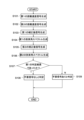
- 5 is a flowchart showing a processing procedure for determining an unnecessary signal in the present embodiment.
- FIG. 13 is a diagram showing a processing procedure in a modified example.
- FIG. 1 is a block diagram showing an example of the configuration of a vehicle control system.
- FIG. 2 is a diagram showing an example of a sensing region.
- Radar device 1 is a block diagram showing a configuration of a radar device 200 used in an embodiment of the present technology.
- the radar device 200 includes a transmission device 210 and a determination device 220.
- the transmission device 210 includes a transmission antenna array 210A and a signal generation unit 210B. The configuration of each device will be described below.
- the transmitting antenna array 210A includes multiple transmitting antennas that each transmit multiple chirp signals.
- the transmitting antenna array 210A and the receiving antenna array 220A configure a horizontal MIMO or vertical MIMO.
- the receiving antenna array 220A includes multiple receiving antennas that receive multiple chirp signals reflected by the object 300.
- Figure 2 shows a schematic diagram of the horizontal MIMO concept.
- Figure 3 shows a schematic diagram of the vertical MIMO concept.
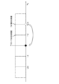
- the MIMO mentioned above is a method of virtually increasing the aperture length ( ⁇ antenna receiving area) by arranging multiple (in this example, two) transmitting antennas (first transmitting antenna 211A, second transmitting antenna 212A) with a spatial offset relative to multiple (in this example, eight) receiving antennas.
- Arranging multiple transmitting antennas with a horizontal offset improves the horizontal resolution (see Figure 2).
- VA1 is a virtual array and represents various combinations of transmitting and receiving antennas.
- a MIMO including multiple transmitting antennas and multiple receiving antennas is considered to be a virtual SIMO (single input multiple output), which is a mathematically equivalent antenna array, and there are (number of transmitting antennas x number of receiving antennas) receiving antennas and one transmitting antenna.
- Arranging multiple transmitting antennas with a vertical offset enables detection in the vertical direction in addition to the horizontal direction (see Figure 3).
- VA2, like VA1 is also a virtual array and represents various combinations of transmit and receive antennas.
- the signal generating unit 210B has a function of generating a plurality of chirp signals to be transmitted from the above-mentioned transmitting antenna array 210A.
- the signal generating unit 210B has a first chirp signal generating unit 211B, a second chirp signal generating unit 212B, a timing control unit 213B, and a first memory unit 214B.
- the first memory unit 214B is an information storage device such as a semiconductor memory or a hard disk.
- the first memory unit 214B stores a program for operating the signal generating unit 210B.
- the first chirp signal generating unit 211B generates the first transmission chirp signal TX1 transmitted from the first transmitting antenna 211A described above, and the second chirp signal generating unit 212B generates the second transmission chirp signal TX2 transmitted from the second transmitting antenna 212A described above.
- generating does not mean simply generating a chirp signal, but also transmitting a chirp signal.
- the first chirp signal generating unit 211B also transmits the transmitted first transmission chirp signal TX1 to the determination processing unit 220B. This makes it possible to generate a beat signal, which will be described later.
- the second chirp signal generating unit 212B also transmits the transmitted second transmission chirp signal TX2 to the determination processing unit 220B in the same manner as the first chirp signal generating unit 211B.
- the timing control unit 213B controls the timing of generating (transmitting) the first transmission chirp signal TX1 and the second transmission chirp signal TX2 toward the outside (object 300).
- TDM-MIMO time division multiplexing
- Figure 4 shows a schematic diagram of the concept of TDM-MIMO.
- the chirp signals transmitted from the transmitting antennas forming the MIMO are transmitted in a time-division manner by the number of transmitting antennas.
- the two transmitting antennas transmit the transmitting chirp signals TX1 and TX2 alternately.
- phase shift occurs due to the difference in speed and time between the receiving signal (first reflected chirp signal RX1 described later) formed by the first transmitting chirp signal TX1 transmitted from the first transmitting antenna 211A and the receiving signal (second reflected chirp signal RX2 described later) formed by the second transmitting chirp signal TX2 transmitted from the second transmitting antenna 212A.
- the timing control unit 213B may also control the timing of generating (transmitting) the first transmission chirp signal TX1 and the second transmission chirp signal TX2 to the determination processing unit 220B. That is, for example, the timing control unit 213B may transmit the first transmission chirp signal TX1 and the second transmission chirp signal TX2 to the outside as well as to the beat signal generating unit 221B.
- the beat signal generating unit 221B can determine whether it is the first transmission chirp signal TX1 or the second transmission chirp signal TX2, for example, based on the timing of transmission from the signal generating unit 210B.
- the determination device 220 has a receiving antenna array (receiving section) 220A and a determination processing section 220B. As described above, the receiving antenna array 220A receives a first reflected chirp signal RX1 resulting from the first transmitted chirp signal TX1 being reflected by the object 300, and a second reflected chirp signal RX2 resulting from the second transmitted chirp signal TX2 being reflected by the object 300. In this embodiment, the receiving antenna array 220A includes eight receiving antennas, but of course the number is not limited to eight and may be, for example, ten.
- the determination processing unit 220B has a function of determining whether or not an unwanted signal is present in a reflected chirp signal that is the result of the transmitted chirp signal being reflected by the object 300.
- the determination processing unit 220B has a beat signal generating unit 221B, a conversion processing unit 222B, a aliasing correction unit 223B, an arrival angle information generating unit 224B, a determination unit 225B, and a second memory unit 226B.
- the second memory unit 226B is an information storage device such as a semiconductor memory or a hard disk.
- the second memory unit 226B stores a program for operating the determination processing unit 220B.
- the beat signal generating unit 221B generates a beat signal based on the reflected chirp signal and the transmitted chirp signal transmitted from the first chirp signal generating unit 211B and the second chirp signal generating unit 212B.
- the beat signal is a signal that is generated by mixing the reflected chirp signal with the transmitted chirp signal, and the frequency component of the signal is the difference in frequency between the reflected chirp signal and the transmitted chirp signal.
- the beat signal is also called an IF (Intermediate Frequency) signal.
- the beat signal generating unit 221B mixes the first transmitted chirp signal TX1 and the first reflected chirp signal RX1 transmitted from the first chirp signal generating unit 211B to generate a first beat signal IF1, and mixes the second transmitted chirp signal TX2 and the second reflected chirp signal RX2 transmitted from the second chirp signal generating unit 212B to generate a second beat signal IF2.
- the transform processing unit 222B performs Fourier transform processing (Fast Fourier transform processing (FFT) or Discrete Fourier transform processing (DFT)) on the distance axis and the velocity axis based on the reflected chirp signal to generate a distance/velocity signal.
- the distance/velocity signal includes distance information on the distance from the receiver 220A (determination device 220) to the object 300 and velocity information on the velocity (or relative velocity) of the object.
- the distance/velocity signal is represented, for example, by a graph in which the X-axis direction is the distance bin, the Y-axis direction perpendicular to the X-axis direction is the velocity bin, and the Z-axis direction perpendicular to the X-axis and Y-axis is the signal strength.
- the distance to the object 300 and the velocity (or relative velocity) of the object 300 are calculated based on the signal strength of the distance/velocity signal.
- the conversion processing unit 222B performs Fourier transform processing based on the first beat signal IF1 to generate a first distance/velocity signal D1 including first distance information related to the distance from the receiving unit 220A (determination device 220, radar device 200) to the object 300 and first velocity information related to the velocity (or relative velocity) of the object 2, and performs Fourier transform processing based on the second beat signal IF2 to generate a second distance/velocity signal D2 including second distance information related to the distance from the receiving unit 220A (determination device 220, radar device 200) to the object 2 and second velocity information related to the velocity (or relative velocity) of the object 2.
- the foldback correction unit 223B performs a process of performing a velocity foldback correction process on the distance/speed signal.
- the foldback correction unit 223B performs a correction process on the first distance/speed signal D1 and the second distance/speed signal D2, which corresponds to a velocity foldback count of 0, to generate a first virtually arrayed corrected signal H1.
- the foldback correction unit 223B also performs a correction process on the first distance/speed signal D1 and the second distance/speed signal D2, which corresponds to a velocity foldback count of 1, to generate a second virtually arrayed corrected signal H2.
- the velocity foldback correction process will be described later.
- the arrival angle information generating unit 224B also performs a Fourier transform process on the first corrected signal H1 to generate an arrival angle spectrum S1.
- the arrival angle information generating unit 224B also performs a Fourier transform process on the second corrected signal H2 to generate an arrival angle spectrum S2.
- Figure 5 shows a schematic diagram of the concept of velocity phase error in TDM-MIMO
- Figure 6 shows a schematic diagram of the concept of velocity phase error correction in TDM-MIMO
- Figure 7 shows a schematic diagram of the concept of the limit of velocity phase correction due to velocity ambiguity.
- the speed of an object can be calculated by performing an FFT (fast Fourier transform) (speed FFT) in the chirp direction on each of the chirp signals TX1 and TX2 after the chirp signals multiplexed between multiple transmitting antennas in TDM-MIMO are separated for each transmitting antenna.
- the speed FFT can also detect phase advance and delay due to speed.
- the phase advance between the multiple chirp signals TX1 from the first transmitting antenna 211A is + ⁇ depending on the speed.
- phase difference due to the speed FFT can only be detected from - ⁇ to + ⁇ .
- the phase due to the speed can exceed + ⁇ .
- the phase difference between the chirps of the multiple chirp signal TX1 from the first transmitting antenna 211A is +2 ⁇
- FFT when FFT is performed, the phase difference of +2 ⁇ will be folded back to +0.
- Figure 8 shows a schematic of the concept of velocity phase correction due to velocity ambiguity.
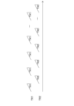
- chirp signals are transmitted so that the transmission timing of each chirp signal TX is equally spaced with respect to the burst interval TB.
- the burst interval TB is the interval between multiple chirp signals from the same antenna when the chirp signals multiplexed between the transmitting antennas are separated for each transmitting antenna.
- the first transmitting chirp signal TX1 from the first transmitting antenna 211A is transmitted at equal intervals with a timing of 0 [ ⁇ s]
- the second chirp signal TX2 from the second transmitting antenna 212A is transmitted at equal intervals with a timing of TB ⁇ 1/2 [ ⁇ s].
- the angular velocity ⁇ can be calculated using equation (1).
- Figure 9 shows the correction of phase difference due to velocity ambiguity.
- phase difference between the chirp signals TX1 and TX2 is ⁇ .
- phase correction speed wrap correction process
- phase correction speed wrap correction process
- Figure 10 shows the angle of arrival spectrum corresponding to (A) and (B) in Figure 9. Only when the phase difference between the chirp signals TX1 and TX2 is corrected, the main lobe of the angle of arrival spectrum (AoA (Angle of Arrival) spectrum) has a maximum value, and the ratio of the main lobe to the side lobe is also maximized.
- AoA Angle of Arrival
- MIMO speed phase correction and AoA can be performed for multiple possible speeds, and the speed candidate with the greater power can be determined as the true speed.
- Speed expansion makes it possible to detect the true speed even if the speed wraps around. Also, knowing the true speed makes it possible to prevent power drops, ghosting, false detection, etc.
- the velocity aliasing correction process detects the occurrence of aliasing, corrects the FFT results, and calculates the arrival angle spectrum, making it possible to obtain an accurate velocity. This process can determine the correct velocity when the received signal is a reflected signal from a target and has a uniquely determined arrival angle.
- the determination unit 225B determines whether or not an unwanted signal is present from the multiple arrival angle spectra generated by the aliasing correction unit 223B and the arrival angle information generation unit 224B.
- the unwanted signal is an interference signal transmitted from a transmission device other than the transmission device 210 (for example, a transmission device of an oncoming vehicle), and in this embodiment, parallel interference (constant interference, close interference) is assumed.
- parallel interference constant interference, close interference
- Figure 11 is a diagram showing a schematic diagram of a transmission signal, where (A) shows the transmission chirp signals TX1, TX2 and the reception signals RX1, RX2, (B) shows a state in which one pulse I1 of the parallel interference has entered, and (C) shows a state in which a signal I2 with synchronized timing has entered from the parallel interference.
- Parallel interference includes interference with other FMCW radars that have roughly the same frequency sweep timing.
- parallel interference is interference caused by the intrusion of a signal with roughly the same frequency gradient as the transmission chirp signals TX1 and TX2 transmitted from the transmitter 210.
- the unwanted signal also includes multipath, a phenomenon in which radar waves are reflected off the road surface, wall surfaces, etc., and received waves from the same object are detected via multiple paths.
- the determination unit 225B determines whether there is parallel interference and multipath interference (unwanted signals).
- the judgment unit 225B judges that no unwanted signal is present if there is only one arrival angle spectrum among the multiple arrival angle spectra in which the intensity of the second peak, which has the next highest reception intensity after the first peak, is equal to or lower than a predetermined intensity relative to the intensity of the first peak, among the multiple arrival angle spectra (first judgment); judges that an unwanted signal is present if there are multiple arrival angle spectra among the multiple arrival angle spectra in which the intensity of the second peak is equal to or lower than a predetermined intensity relative to the intensity of the first peak (second judgment); and judges that an unwanted signal is present if there is no arrival angle spectrum among the multiple arrival angle spectra in which the intensity of the second peak is equal to or lower than a predetermined intensity relative to the intensity of the first peak (third judgment).
- the received signal is normal. If there is no velocity fold number that correctly corrects the phase difference between chirp signals TX1 and TX2, or if there are multiple velocity fold numbers that correctly correct the phase difference, the received signal is determined to be a false signal caused by interference or a signal caused by unwanted reflection.
- Figure 12 is a diagram showing the aliasing correction process in the case of Figure 11 (A).
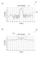
- Figure 13 shows the arrival angle spectrum when no unwanted signal is present, where (A) is the correct spectrum and (B) is the incorrect spectrum.
- "0" and " ⁇ " shown in FIG. 12 indicate the phase shift, and are expressed in units of, for example, radians.
- the first distance/speed signal D1 and the second distance/speed signal D2 have no phase shift
- the first angle-of-arrival spectrum S1 shown in FIG. 13(A) is the spectrum obtained when AoA is performed (Fourier transform processing is performed) on the first corrected signal H1 shown in FIG. 12
- the second angle-of-arrival spectrum S2 shown in FIG. 13(B) is the spectrum obtained when AoA is performed (Fourier transform processing is performed) on the second corrected signal H2 shown in FIG. 12.
- a correct spectrum is an arrival angle spectrum in which the second peak P2 is equal to or lower than a predetermined value relative to the intensity (dB) of the first peak P1.
- an incorrect spectrum is an arrival angle spectrum in which the second peak (P2) is not equal to or lower than a predetermined value relative to the intensity (dB) of the first peak P1.
- equal to or lower than a predetermined value means, for example, 30 dB lower than the reception intensity of the first peak P1, but of course it is not limited to 30 dB and may be 10 dB or 40 dB. It is also not limited to this and may be equal to or lower than half or one third of the reception intensity of the first peak P1.
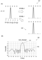
- Figure 14 shows the processing of the judgment processing unit 220B in the case of Figure 11 (B), (A) shows the aliasing correction processing, and (B) shows the third arrival angle spectrum S3.
- the third arrival angle spectrum S3 shown in FIG. 14(B) is a spectrum when the number of velocity folds is 0 and 1, and there is almost no change in shape.
- “almost no change” means that there is no change in peak intensity or spectrum shape (for example, the shapes are 60% or more identical).
- the third arrival angle spectrum S3 shown in FIG. 14(B) is in a state where a single pulse I1 has intruded, as shown in FIG. 11(B). For this reason, even if a velocity aliasing correction process is performed, there is almost no change in the shape of the spectrum (in other words, the intruding single pulse I1 has caused the peak intensity to increase in some places, and no change in the shape is observed even when the phase is rotated).
- the third arrival angle spectrum S3 in FIG. 14(B) has the same shape whether the number of velocity folds is 0 or 1, and there are multiple arrival angle spectra in which the intensity of the second peak P2 is equal to or lower than a predetermined value relative to the intensity of the first peak P1, and it is judged that an unwanted signal (single pulse I1) is present.
- Figure 15 shows the processing of the judgment processing unit 220B in the case of Figure 11 (C), (A) shows the aliasing correction processing, and (B) shows the fourth arrival angle spectrum S4.
- the phases of D1'' and D2'' do not match regardless of whether the number of velocity wraps is 0 or 1.
- the phases of D1'' and D2'' are always shifted by 1.1 regardless of the velocity wrap.
- the fourth arrival angle spectrum S4 shown in FIG. 15(B) is an erroneous spectrum in both cases where the number of velocity folds is 0 and 1, and its shape shows almost no change.
- almost no change means that the peak intensity and spectrum shape do not change (for example, the shapes are 60% or more identical), as described above.
- the fourth arrival angle spectrum S4 shown in FIG. 15(B) is in a state where the timing-synchronized signal I2 has entered as shown in FIG. 11(B). For this reason, even if a speed wraparound correction process is performed, there is almost no change in the shape of the spectrum (in other words, for example, when the timing-synchronized signal I2 enters from an oncoming vehicle, the phase of the timing-synchronized signal I2 and the phase of the transmission chirp signals TX1 and TX2 transmitted from the transmitter 210 are misaligned, so even if the phase is rotated, no change is observed).
- the fourth arrival angle spectrum S4 in FIG. 15(B) has the same shape (incorrect spectrum shape) whether the number of velocity wraparounds is 0 or 1, and since there is no arrival angle spectrum in which the intensity P2 of the second peak is equal to or less than a predetermined value relative to the intensity of the first peak P1, it is judged that an unwanted signal is present.
- Figure 16 is a flowchart showing the processing procedure for determining whether an unwanted signal is present in this embodiment. The following flowchart will mainly explain the case of Figure 11 (A).
- the conversion processing unit 222B performs Fourier transform processing on the first beat signal generated by the beat signal generating unit 221B based on the first transmitted chirp signal TX1 and the first reflected chirp signal RX1 to generate a first distance velocity signal D1 (step S101).
- the conversion processing unit 22B performs Fourier transform processing on the second beat signal generated by the beat signal generating unit 221B based on the second transmitted chirp signal TX2 and the second reflected chirp signal RX2 to generate a second distance velocity signal D2 (step S102).
- the folding correction unit 23B performs a correction process on the first distance-speed signal D1 and the second distance-speed signal D2 that corresponds to a speed folding count of 0 (i.e., does not correct the phase) to generate a first corrected signal H1 (step S103).
- the arrival angle information generating unit 24B performs AoA (executes Fourier transform processing) on the first corrected signal D1 to generate a first arrival angle spectrum S1 (step S104).
- the folding correction unit 23B performs a correction process (i.e., corrects the phase) on the first distance-speed signal D1 and the second distance-speed signal D2, which corresponds to one folding speed, and generates a second corrected signal H2 (step S105).
- a correction process i.e., corrects the phase
- the arrival angle information generating unit 24B performs AoA (executes Fourier transform processing) on the second corrected signal H2 to generate a second arrival angle spectrum S2 (step S106).
- the determination unit 25B compares the first arrival angle spectrum S1 with the second arrival angle spectrum S2, and determines whether the result is the first determination result described above (step S107).
- step S107 it is determined that no unwanted signal is present and that the object 300 is an actually existing target (step S108). That is, in the case of FIG. 11(A), step S107 is YES. If step S107 is NO, the second or third judgment result is obtained and it is determined that an unwanted signal due to parallel interference or multipath is present (step S109). That is, in the cases of FIG. 11(B) and (C), step S107 is NO, the second or third judgment result is obtained, and it is determined that an unwanted signal is present.
- the determination device 220 determines whether or not an unwanted signal is present using the arrival angle spectrum calculated to detect (estimate) the angle or speed (relative speed) of the object 300 relative to the receiving unit 220A (determination device 220, radar device 200).
- transmission chirp signals are transmitted from different transmitting antennas (first transmitting antenna 101A, second transmitting antenna 102A) by time division.
- transmission chirp signals may be transmitted from the same transmitting antenna by phase division.
- a process is executed to average the distance/rate signal D and the first corrected signal H obtained by performing zero velocity folding on the distance/rate signal D to generate a first averaged signal Av1. Also, a process is executed to average the distance/rate signal D and the second corrected signal H' obtained by performing one velocity folding on the distance/rate signal D to generate a second averaged signal Av2.
- the averaging referred to here is a process of averaging the phases of the distance/rate signal D and the first corrected signal H'. For example, if the phase of the first corrected signal H' corrected by velocity folding is shifted by + ⁇ from the phase of the distance/rate signal D, then by performing the averaging process, the phase of the first averaged signal Av1 will be shifted by + ⁇ /2 from the phase of the distance/rate signal D.
- AoA is performed on the first averaged signal Av1 in the same manner as in step S104 above, and AoA is performed on the second averaged signal Av2 in the same manner as in step S106 above.
- the unwanted signal shown in FIG. 11B is a signal by single-input multiple-output (SIMO), but of course, this is not limited to this, and for example, it may be a case where an oncoming vehicle uses MIMO and its signal enters. Even in this case, it is possible to determine whether or not an unwanted signal exists.
- the speed aliasing correction process phase correction
- the speed aliasing correction process may be performed on the first distance/speed signal D1.
- whether the spectrum is correct is determined based on the difference between the reception strength of the first peak P1 and the reception strength of the second peak P2, but of course this is not limited to this, and it may be determined based on whether the arrival angle spectra of each other have a predetermined matching rate (e.g., 60% or more) or more.
- a predetermined matching rate e.g. 60% or more
- the matching rate between multiple arrival angle spectra is below a predetermined value (corresponding to the diagram in this embodiment), it can be determined that no unwanted signal is present, and if the matching rate between multiple arrival angle spectra is not below a predetermined value, it can be determined that an unwanted signal is present. And, among the multiple arrival angle spectra determined to not contain an unwanted signal, if the difference between the reception intensity of the first peak P1 and the reception intensity of the second peak P2 is above a predetermined value as described above, it can be determined to be a correct spectrum.
- the speed wraparound correction process is performed 0 and 1 time, but it is not limited to this and may be performed 0 to 2 or more times.
- the phase correction range in this embodiment is expanded from - ⁇ to + ⁇ to -2 ⁇ to +2 ⁇ , but by further widening this phase correction range, the speed wraparound correction process (number of wraparounds) can be expanded to 2 or 3 times.
- FIG. 18 is a block diagram showing an example of the configuration of a vehicle control system 11, which is an example of a mobility device control system to which the present technology is applied.
- the vehicle control system 11 is provided in the vehicle 1 and performs processing related to the automated driving of the vehicle 1.
- This automated driving includes driving automation of levels 1 to 5, as well as remote driving and remote assistance of the vehicle 1 by a remote driver.
- the vehicle control system 11 includes a vehicle control ECU (Electronic Control Unit) 21, a communication unit 22, a map information storage unit 23, a location information acquisition unit 24, an external recognition sensor 25, an in-vehicle sensor 26, a vehicle sensor 27, a memory unit 28, a driving automation control unit 29, a DMS (Driver Monitoring System) 30, an HMI (Human Machine Interface) 31, and a vehicle control unit 32.
- vehicle control ECU Electronic Control Unit
- communication unit 22 includes a vehicle control ECU (Electronic Control Unit) 21, a communication unit 22, a map information storage unit 23, a location information acquisition unit 24, an external recognition sensor 25, an in-vehicle sensor 26, a vehicle sensor 27, a memory unit 28, a driving automation control unit 29, a DMS (Driver Monitoring System) 30, an HMI (Human Machine Interface) 31, and a vehicle control unit 32.
- the vehicle control ECU 21, communication unit 22, map information storage unit 23, position information acquisition unit 24, external recognition sensor 25, in-vehicle sensor 26, vehicle sensor 27, memory unit 28, driving automation control unit 29, DMS 30, HMI 31, and vehicle control unit 32 are connected to each other so as to be able to communicate with each other via a communication network 41.
- the communication network 41 is composed of an in-vehicle communication network or bus that complies with digital two-way communication standards such as CAN (Controller Area Network), LIN (Local Interconnect Network), LAN (Local Area Network), FlexRay (registered trademark), and Ethernet (registered trademark).
- the communication network 41 may be used differently depending on the type of data being transmitted.
- CAN may be applied to data related to vehicle control
- Ethernet may be applied to large-volume data.
- each part of the vehicle control system 11 may be directly connected without going through the communication network 41, using wireless communication intended for communication over relatively short distances, such as near field communication (NFC) or Bluetooth (registered trademark).
- NFC near field communication
- Bluetooth registered trademark
- the vehicle control ECU 21 is composed of various processors, such as a CPU (Central Processing Unit) and an MPU (Micro Processing Unit).
- the vehicle control ECU 21 controls all or part of the functions of the vehicle control system 11.
- the communication unit 22 communicates with various devices inside and outside the vehicle, other vehicles, servers, base stations, etc., and transmits and receives various types of data. At this time, the communication unit 22 can communicate using multiple communication methods.
- the communication unit 22 communicates with servers (hereinafter referred to as external servers) on an external network via base stations or access points using wireless communication methods such as 5G (fifth generation mobile communication system), LTE (Long Term Evolution), and DSRC (Dedicated Short Range Communications).
- the external network with which the communication unit 22 communicates is, for example, the Internet, a cloud network, or an operator-specific network.
- the communication method that the communication unit 22 uses with the external network is not particularly limited as long as it is a wireless communication method that allows digital two-way communication at a communication speed equal to or higher than a predetermined distance.
- the communication unit 22 can communicate with a terminal present in the vicinity of the vehicle using P2P (Peer To Peer) technology.
- the terminal present in the vicinity of the vehicle can be, for example, a terminal attached to a mobile object moving at a relatively slow speed, such as a pedestrian or a bicycle, a terminal installed at a fixed position in a store, or an MTC (Machine Type Communication) terminal.
- the communication unit 22 can also perform V2X communication.
- V2X communication refers to communication between the vehicle and others, such as vehicle-to-vehicle communication with other vehicles, vehicle-to-infrastructure communication with roadside devices, vehicle-to-home communication with a home, and vehicle-to-pedestrian communication with a terminal carried by a pedestrian, etc.
- the communication unit 22 can, for example, receive from the outside a program for updating the software that controls the operation of the vehicle control system 11 (Over the Air).
- the communication unit 22 can further receive map information, traffic information, information about the surroundings of the vehicle 1, etc. from the outside.
- the communication unit 22 can also transmit information about the vehicle 1 and information about the surroundings of the vehicle 1 to the outside.
- Information about the vehicle 1 that the communication unit 22 transmits to the outside includes, for example, data indicating the state of the vehicle 1, the recognition results by the recognition unit 73, etc.
- the communication unit 22 performs communication corresponding to a vehicle emergency notification system such as e-Call.
- the communication unit 22 receives electromagnetic waves transmitted by a road traffic information and communication system (VICS (Vehicle Information and Communication System) (registered trademark)) such as a radio beacon, optical beacon, or FM multiplex broadcasting.
- VICS Vehicle Information and Communication System
- the communication unit 22 can communicate with each device in the vehicle using, for example, wireless communication.
- the communication unit 22 can perform wireless communication with each device in the vehicle using a communication method that allows digital two-way communication at a communication speed equal to or higher than a predetermined speed via wireless communication, such as wireless LAN, Bluetooth, NFC, or WUSB (Wireless USB).
- the communication unit 22 can also communicate with each device in the vehicle using wired communication.
- the communication unit 22 can communicate with each device in the vehicle using wired communication via a cable connected to a connection terminal (not shown).
- the communication unit 22 can communicate with each device in the vehicle using a communication method that allows digital two-way communication at a communication speed equal to or higher than a predetermined speed via wired communication, such as USB (Universal Serial Bus), HDMI (High-Definition Multimedia Interface) (registered trademark), or MHL (Mobile High-definition Link).
- a communication method that allows digital two-way communication at a communication speed equal to or higher than a predetermined speed via wired communication, such as USB (Universal Serial Bus), HDMI (High-Definition Multimedia Interface) (registered trademark), or MHL (Mobile High-definition Link).
- the in-vehicle device refers to, for example, a device that is not connected to the communication network 41 inside the vehicle.
- examples of in-vehicle devices include mobile devices and wearable devices carried by users inside the vehicle, such as the driver, and information devices brought into the vehicle and temporarily installed.
- the map information storage unit 23 stores one or both of a map acquired from an external source and a map created by the vehicle 1.
- the map information storage unit 23 stores a three-dimensional high-precision map, a global map that is less accurate than a high-precision map and covers a wide area, etc.
- High-precision maps include, for example, dynamic maps, point cloud maps, and vector maps.
- a dynamic map is, for example, a map consisting of four layers of dynamic information, semi-dynamic information, semi-static information, and static information, and is provided to the vehicle 1 from an external server or the like.
- a point cloud map is a map made up of a point cloud (point cloud data).
- a vector map is, for example, a map that is adapted for driving automation by associating traffic information such as the positions of lanes and traffic lights with a point cloud map.
- the point cloud map and vector map may be provided, for example, from an external server, or may be created by the vehicle 1 based on sensing results from the camera 51, radar 52, LiDAR 53, etc. as a map for matching with a local map described below, and stored in the map information storage unit 23.
- map data of, for example, an area of several hundred meters square regarding the planned route along which the vehicle 1 will travel is acquired from the external server, etc., in order to reduce communication capacity.
- the location information acquisition unit 24 receives GNSS signals from Global Navigation Satellite System (GNSS) satellites and acquires location information of the vehicle 1.
- GNSS Global Navigation Satellite System
- the acquired location information is supplied to the driving automation control unit 29.
- the location information acquisition unit 24 is not limited to a method using GNSS signals, and may acquire location information using a beacon, for example.
- the external recognition sensor 25 includes various sensors used to recognize the situation outside the vehicle 1, and supplies sensor data from each sensor to each part of the vehicle control system 11.
- the type and number of sensors included in the external recognition sensor 25 are arbitrary.
- the external recognition sensor 25 includes a camera 51, a radar 52, a LiDAR (Light Detection and Ranging, Laser Imaging Detection and Ranging) 53, and an ultrasonic sensor 54.
- the external recognition sensor 25 may be configured to include one or more types of sensors among the camera 51, the radar 52, the LiDAR 53, and the ultrasonic sensor 54.
- the number of cameras 51, radars 52, LiDAR 53, and ultrasonic sensors 54 is not particularly limited as long as it is a number that can be realistically installed on the vehicle 1.
- the types of sensors included in the external recognition sensor 25 are not limited to this example, and the external recognition sensor 25 may include other types of sensors. Examples of the sensing areas of each sensor included in the external recognition sensor 25 will be described later.
- the imaging method of camera 51 is not particularly limited.
- cameras of various imaging methods such as a ToF (Time Of Flight) camera, a stereo camera, a monocular camera, and an infrared camera, which are imaging methods capable of distance measurement, can be applied to camera 51 as necessary.
- ToF Time Of Flight
- stereo camera stereo camera
- monocular camera stereo camera
- infrared camera infrared camera
- the present invention is not limited to this, and camera 51 may simply be used for acquiring photographic images, without regard to distance measurement.
- the external recognition sensor 25 can be equipped with an environmental sensor for detecting the environment relative to the vehicle 1.
- the environmental sensor is a sensor for detecting the environment such as the weather, climate, brightness, etc., and can include various sensors such as a raindrop sensor, a fog sensor, a sunlight sensor, a snow sensor, an illuminance sensor, etc.
- the external recognition sensor 25 includes a microphone that is used to detect sounds around the vehicle 1 and the location of sound sources.
- the in-vehicle sensor 26 includes various sensors for detecting information inside the vehicle, and supplies sensor data from each sensor to each part of the vehicle control system 11. There are no particular limitations on the types and number of the various sensors included in the in-vehicle sensor 26, so long as they are of the types and number that can be realistically installed in the vehicle 1.
- the in-vehicle sensor 26 may be equipped with one or more types of sensors including a camera, radar, a seating sensor, a steering wheel sensor, a microphone, and a biometric sensor.
- the camera equipped in the in-vehicle sensor 26 may be a camera using various imaging methods capable of measuring distances, such as a ToF camera, a stereo camera, a monocular camera, or an infrared camera. Without being limited to this, the camera equipped in the in-vehicle sensor 26 may be a camera simply for acquiring captured images, regardless of distance measurement.
- the biometric sensor equipped in the in-vehicle sensor 26 is provided, for example, on a seat, steering wheel, etc., and detects various types of biometric information of the user.
- the vehicle sensor 27 includes various sensors for detecting the state of the vehicle 1, and supplies sensor data from each sensor to each part of the vehicle control system 11. There are no particular limitations on the types and number of the various sensors included in the vehicle sensor 27, so long as they are of the types and number that can be realistically installed on the vehicle 1.
- the vehicle sensor 27 includes a speed sensor, an acceleration sensor, an angular velocity sensor (gyro sensor), and an inertial measurement unit (IMU) that integrates these.
- the vehicle sensor 27 includes a steering angle sensor that detects the steering angle of the steering wheel, a yaw rate sensor, an accelerator sensor that detects the amount of accelerator pedal operation, and a brake sensor that detects the amount of brake pedal operation.
- the vehicle sensor 27 includes a rotation sensor that detects the number of rotations of the engine or motor, an air pressure sensor that detects the air pressure of the tires, a slip ratio sensor that detects the slip ratio of the tires, and a wheel speed sensor that detects the rotation speed of the wheels.
- the vehicle sensor 27 includes a battery sensor that detects the remaining charge and temperature of the battery, and an impact sensor that detects external impacts.
- the memory unit 28 includes at least one of a non-volatile storage medium and a volatile storage medium, and stores data and programs.
- the memory unit 28 is used, for example, as an EEPROM (Electrically Erasable Programmable Read Only Memory) and a RAM (Random Access Memory), and the storage medium may be a magnetic storage device such as a hard disc drive (HDD), a semiconductor storage device, an optical storage device, or a magneto-optical storage device.
- the memory unit 28 stores various programs and data used by each part of the vehicle control system 11.
- the memory unit 28 includes an EDR (Event Data Recorder) and a DSSAD (Data Storage System for Automated Driving), and stores information about the vehicle 1 before and after an event such as an accident, and information acquired by the in-vehicle sensor 26.
- EDR Event Data Recorder
- DSSAD Data Storage System for Automated Driving
- the driving automation control unit 29 controls the driving automation function of the vehicle 1.
- the driving automation control unit 29 includes an analysis unit 61, an action planning unit 62, and an operation control unit 63.
- the analysis unit 61 performs analysis processing of the vehicle 1 and the surrounding conditions.
- the analysis unit 61 includes a self-position estimation unit 71, a sensor fusion unit 72, and a recognition unit 73.
- the self-position estimation unit 71 estimates the self-position of the vehicle 1 based on the sensor data from the external recognition sensor 25 and the high-precision map stored in the map information storage unit 23. For example, the self-position estimation unit 71 generates a local map based on the sensor data from the external recognition sensor 25, and estimates the self-position of the vehicle 1 by matching the local map with the high-precision map.
- the position of the vehicle 1 is based on, for example, the center of the rear wheel pair axle.
- the local map is, for example, a three-dimensional high-precision map or an occupancy grid map created using technology such as SLAM (Simultaneous Localization and Mapping).
- the three-dimensional high-precision map is, for example, the point cloud map described above.
- the occupancy grid map is a map in which the three-dimensional or two-dimensional space around the vehicle 1 is divided into grids of a predetermined size, and the occupancy state of objects is shown on a grid-by-grid basis.
- the occupancy state of objects is indicated, for example, by the presence or absence of an object and the probability of its existence.
- the local map is also used, for example, in detection processing and recognition processing of the situation outside the vehicle 1 by the recognition unit 73.
- the self-position estimation unit 71 may estimate the self-position of the vehicle 1 based on the position information acquired by the position information acquisition unit 24 and the sensor data from the vehicle sensor 27.
- the sensor fusion unit 72 performs sensor fusion processing to obtain information by combining multiple different types of sensor data (e.g., image data supplied from the camera 51 and sensor data supplied from the radar 52). Methods for combining different types of sensor data include compounding, integration, fusion, and association.
- the recognition unit 73 executes a detection process to detect the situation outside the vehicle 1, and a recognition process to recognize the situation outside the vehicle 1.
- the recognition unit 73 performs detection and recognition processing of the situation outside the vehicle 1 based on information from the external recognition sensor 25, information from the self-position estimation unit 71, information from the sensor fusion unit 72, etc.
- the recognition unit 73 performs detection processing and recognition processing of objects around the vehicle 1.
- Object detection processing is, for example, processing to detect the presence or absence, size, shape, position, movement, etc. of an object.
- Object recognition processing is, for example, processing to recognize attributes such as the type of object, and to identify a specific object.
- detection processing and recognition processing are not necessarily clearly separated, and there may be overlap.
- the recognition unit 73 detects objects around the vehicle 1 by performing clustering to classify a point cloud based on sensor data from the radar 52, the LiDAR 53, or the like into clusters of points. This allows the presence or absence, size, shape, and position of objects around the vehicle 1 to be detected.
- the recognition unit 73 detects the movement of objects around the vehicle 1 by performing tracking to follow the movement of clusters of point clouds classified by clustering. This allows the speed and direction of travel (movement vector) of objects around the vehicle 1 to be detected.
- the recognition unit 73 detects or recognizes vehicles, people, bicycles, obstacles, structures, roads, traffic lights, traffic signs, road markings, etc. based on image data supplied from the camera 51.
- the recognition unit 73 may also recognize the types of objects around the vehicle 1 by performing recognition processing such as semantic segmentation.
- the recognition unit 73 can perform recognition processing of traffic rules around the vehicle 1 based on the map stored in the map information storage unit 23, the result of self-location estimation by the self-location estimation unit 71, and the result of recognition of objects around the vehicle 1 by the recognition unit 73. Through this processing, the recognition unit 73 can recognize the positions and states of traffic lights, the contents of traffic signs and road markings, the contents of traffic regulations, and lanes on which travel is possible, etc.
- the recognition unit 73 can perform recognition processing of the environment around the vehicle 1.
- the surrounding environment that the recognition unit 73 recognizes may include weather, temperature, humidity, brightness, and road surface conditions.
- the behavior planning unit 62 creates a behavior plan for the vehicle 1. For example, the behavior planning unit 62 creates the behavior plan by performing route planning and route following processing.
- Route planning includes global path planning and local path planning.
- Global path planning involves planning a rough route from the start to the goal.
- Local path planning is also called trajectory planning, and involves generating a trajectory that allows safe and smooth progress in the vicinity of vehicle 1 on the planned route, taking into account the motion characteristics of vehicle 1.
- Path following is a process of planning operations for safely and accurately traveling along a route planned by a route plan within a planned time.
- the action planning unit 62 can, for example, calculate the target speed and target angular velocity of the vehicle 1 based on the results of this path following process.
- the operation control unit 63 controls the operation of the vehicle 1 to realize the action plan created by the action planning unit 62.
- the operation control unit 63 controls the steering control unit 81, the brake control unit 82, and the drive control unit 83 included in the vehicle control unit 32 described below, and performs lateral vehicle motion control and longitudinal vehicle motion control so that the vehicle 1 proceeds along the trajectory calculated by the trajectory plan.
- the operation control unit 63 performs control aimed at driving automation, such as driver assistance functions such as collision avoidance or impact mitigation, following driving, maintaining vehicle speed, collision warning for the vehicle itself, and lane departure warning for the vehicle itself, and driving without the operation of the driver or a remote driver.
- the DMS 30 performs processes such as authenticating the driver and recognizing the driver's state based on the sensor data from the in-vehicle sensors 26 and the input data input to the HMI 31 (described later).
- Examples of the driver's state to be recognized include physical condition, alertness, concentration, fatigue, line of sight, level of intoxication, driving operation, posture, etc.
- the DMS 30 may also perform authentication processing for users other than the driver and recognition processing for the status of the users.
- the DMS 30 may also perform recognition processing for the status inside the vehicle based on sensor data from the in-vehicle sensor 26. Examples of the status inside the vehicle that may be recognized include temperature, humidity, brightness, odor, etc.
- HMI31 inputs various data and instructions, and displays various data to the user.
- the HMI 31 is equipped with an input device that allows a person to input data.
- the HMI 31 generates input signals based on data and instructions input via the input device, and supplies the signals to each part of the vehicle control system 11.
- the HMI 31 is equipped with input devices such as a touch panel, buttons, switches, and levers. Without being limited to these, the HMI 31 may further be equipped with an input device that allows information to be input by a method other than manual operation, such as voice or gestures.
- the HMI 31 may use, as an input device, an externally connected device such as a remote control device that uses infrared or radio waves, or a mobile device or wearable device that supports the operation of the vehicle control system 11.
- the HMI 31 generates visual information, auditory information, and tactile information for the user or the outside of the vehicle.
- the HMI 31 also performs output control to control the output, output content, output timing, output method, etc. of each piece of generated information.
- the HMI 31 generates and outputs, as visual information, information indicated by images or light, such as an operation screen, vehicle 1 status display, warning display, and monitor image showing the situation around the vehicle 1.
- the HMI 31 also generates and outputs, as auditory information, information indicated by sounds, such as voice guidance, warning sounds, and warning messages.
- the HMI 31 also generates and outputs, as tactile information, information that is imparted to the user's sense of touch by force, vibration, movement, etc.
- the output device from which the HMI 31 outputs visual information may be, for example, a display device that presents visual information by displaying an image itself, or a projector device that presents visual information by projecting an image.
- the display device may be a device that displays visual information within the user's field of vision, such as a head-up display, a transmissive display, or a wearable device with an AR (Augmented Reality) function, in addition to a display device having a normal display.
- the HMI 31 may also use display devices such as a navigation device, instrument panel, CMS (Camera Monitoring System), electronic mirror, lamp, etc., provided in the vehicle 1 as output devices that output visual information.
- the output device through which the HMI 31 outputs auditory information can be, for example, an audio speaker, headphones, or earphones.
- Haptic elements using haptic technology can be used as an output device for the HMI 31 to output tactile information.
- Haptic elements are provided on parts that the user touches, such as the steering wheel and the seat.
- the vehicle control unit 32 controls each part of the vehicle 1.
- the vehicle control unit 32 includes a steering control unit 81, a brake control unit 82, a drive control unit 83, a body control unit 84, a light control unit 85, and a horn control unit 86.
- the steering control unit 81 detects and controls the state of the steering system of the vehicle 1.
- the steering system includes, for example, a steering mechanism including a steering wheel, an electric power steering, etc.
- the steering control unit 81 includes, for example, a steering ECU that controls the steering system, an actuator that drives the steering system, etc.
- the brake control unit 82 detects and controls the state of the brake system of the vehicle 1.
- the brake system includes, for example, a brake mechanism including a brake pedal, an ABS (Antilock Brake System), a regenerative brake mechanism, etc.
- the brake control unit 82 includes, for example, a brake ECU that controls the brake system, and an actuator that drives the brake system.
- the drive control unit 83 detects and controls the state of the drive system of the vehicle 1.
- the drive system includes, for example, an accelerator pedal, a drive force generating device for generating drive force such as an internal combustion engine or a drive motor, and a drive force transmission mechanism for transmitting the drive force to the wheels.
- the drive control unit 83 includes, for example, a drive ECU for controlling the drive system, and an actuator for driving the drive system.
- the body system control unit 84 detects and controls the state of the body system of the vehicle 1.
- the body system includes, for example, a keyless entry system, a smart key system, a power window device, a power seat, an air conditioning system, an airbag, a seat belt, a shift lever, etc.
- the body system control unit 84 includes, for example, a body system ECU that controls the body system, an actuator that drives the body system, etc.
- the light control unit 85 detects and controls the state of various lights of the vehicle 1. Examples of lights to be controlled include headlights, backlights, fog lights, turn signals, brake lights, projection, and bumper displays.
- the light control unit 85 includes a light ECU that controls the lights, an actuator that drives the lights, and the like.
- the horn control unit 86 detects and controls the state of the car horn of the vehicle 1.
- the horn control unit 86 includes, for example, a horn ECU that controls the car horn, an actuator that drives the car horn, etc.
- FIG. 19 is a diagram showing an example of a sensing area by the camera 51, radar 52, LiDAR 53, ultrasonic sensor 54, etc. of the external recognition sensor 25 in FIG. 18. Note that FIG. 19 shows a schematic view of the vehicle 1 as seen from above, with the left end side being the front end of the vehicle 1 and the right end side being the rear end of the vehicle 1.
- Sensing area 101F and sensing area 101B show examples of sensing areas of ultrasonic sensors 54. Sensing area 101F covers the periphery of the front end of vehicle 1 with multiple ultrasonic sensors 54. Sensing area 101B covers the periphery of the rear end of vehicle 1 with multiple ultrasonic sensors 54.
- sensing results in sensing area 101F and sensing area 101B are used, for example, for parking assistance for vehicle 1.
- Sensing area 102F to sensing area 102B show examples of sensing areas of a short-range or medium-range radar 52. Sensing area 102F covers a position farther in front of the vehicle 1 than sensing area 101F. Sensing area 102B covers a position farther in the rear of the vehicle 1 than sensing area 101B. Sensing area 102L covers the rear periphery of the left side of the vehicle 1. Sensing area 102R covers the rear periphery of the right side of the vehicle 1.
- the sensing results in sensing area 102F are used, for example, to detect vehicles, pedestrians, etc., that are in front of vehicle 1.
- the sensing results in sensing area 102B are used, for example, for collision prevention functions behind vehicle 1.
- the sensing results in sensing area 102L and sensing area 102R are used, for example, to detect objects in blind spots to the sides of vehicle 1.
- Sensing area 103F to sensing area 103B show examples of sensing areas by camera 51. Sensing area 103F covers a position farther in front of vehicle 1 than sensing area 102F. Sensing area 103B covers a position farther in the rear of vehicle 1 than sensing area 102B. Sensing area 103L covers the periphery of the left side of vehicle 1. Sensing area 103R covers the periphery of the right side of vehicle 1.
- the sensing results in sensing area 103F can be used, for example, for recognizing traffic lights and traffic signs, lane departure prevention support systems, and automatic headlight control systems.
- the sensing results in sensing area 103B can be used, for example, for parking assistance and surround view systems.
- the sensing results in sensing area 103L and sensing area 103R can be used, for example, for surround view systems.
- Sensing area 104 shows an example of the sensing area of LiDAR 53. Sensing area 104 covers a position farther in front of vehicle 1 than sensing area 103F. On the other hand, sensing area 104 has a narrower range in the left-right direction than sensing area 103F.
- the sensing results in the sensing area 104 are used, for example, to detect objects such as surrounding vehicles.
- a sensing area 105 shows an example of a sensing area of a long-range radar 52 .
- the sensing area 105 covers a position farther in front of the vehicle 1 than the sensing area 104.
- the sensing area 105 has a narrower range in the left-right direction than the sensing area 104.
- the sensing results in the sensing area 105 are used, for example, for ACC (Adaptive Cruise Control), emergency braking, collision avoidance, etc.
- ACC Adaptive Cruise Control
- emergency braking braking
- collision avoidance etc.
- the sensing areas of the cameras 51, radar 52, LiDAR 53, and ultrasonic sensors 54 included in the external recognition sensor 25 may have various configurations other than those shown in FIG. 2. Specifically, the ultrasonic sensor 54 may also sense the sides of the vehicle 1, and the LiDAR 53 may sense the rear of the vehicle 1.
- the installation positions of the sensors are not limited to the examples described above. The number of sensors may be one or more.
- the radar device 200 of the present disclosure may be applied to the radar 52 of the external recognition sensor 25.
- the presence or absence of generation of unwanted waves such as radio wave interference may be determined, and if it is determined that unwanted waves are generated, a notice may be sent to the user of the vehicle 1 that the radar device 200 may not operate properly.
- the on-board control system 11 may restrict some or all of the driving automation functions that operate based on the sensing results of the radar device 200.
- the present disclosure may have the following configurations.
- a receiving unit that receives a first reflected chirp signal that is a first transmission chirp signal that is transmitted by a transmitting device toward an object and reflected by the object, and a second reflected chirp signal that is a second transmission chirp signal that is irradiated by the transmitting device at a time different from the time when the first transmission chirp signal is irradiated and reflected by the object; a determination processing unit that generates a plurality of angle-of-arrival spectra based on a plurality of corrected signals obtained by performing a plurality of velocity aliasing correction processes on the first reflected chirp signal and the second reflected chirp signal received by the receiving unit, and compares the plurality of angle-of-arrival spectra with each other to determine whether or not an unwanted signal has been received.
- the determination processing unit includes a beat signal generating unit that generates a first beat signal based on the first transmitted chirp signal and the first reflected chirp signal, and generates a second beat signal based on the second transmitted chirp signal and the second reflected chirp signal.
- the determination processing unit has a conversion processing unit that performs Fourier transform processing based on the first reflected chirp signal to generate a first distance velocity signal including a first distance signal related to the distance to the object and a first velocity signal related to the velocity of the object, and performs Fourier transform processing based on the second reflected chirp signal to generate a second distance velocity signal including a second distance signal related to the distance to the object and a second velocity signal related to the velocity of the object.
- the determination device described in (1) or (2) above.
- the determination processing unit The determination device according to any one of (1) to (3), further comprising a determination unit that determines that no unnecessary signal is present when there is only one arrival angle spectrum among the multiple arrival angle spectra in which the intensity of a second peak having the next highest reception intensity after a first peak is equal to or less than a predetermined intensity relative to the intensity of a first peak at which the reception intensity for the arrival angle of the first reflected chirp signal and the second reflected chirp signal is maximum, and determines that the unnecessary signal is present when there are multiple arrival angle spectra among the multiple arrival angle spectra in which the intensity of the second peak is equal to or less than a predetermined intensity relative to the intensity of the first peak and when there is no arrival angle spectrum among the multiple arrival angle spectra in which the intensity of the second peak is equal to or less than the predetermined intensity relative to the intensity of the first peak.
- the determination device according to any one of (1) to (4), wherein the unnecessary signal is an interference signal transmitted from a transmitting device other than the transmitting device.
- the unnecessary signal is a signal that is the first transmission chirp signal transmitted from the transmitting device, reflected by the object and also reflected by another object different from the object.
- a method for determining whether or not an unwanted signal is received comprising: generating a plurality of angle-of-arrival spectra based on a plurality of corrected signals obtained by performing a plurality of velocity aliasing correction processes on the received first reflected chirp signal and the second reflected chirp signal; and comparing the plurality of angle-of-arrival spectra with each other.
- a transmitting device that transmits a first transmission chirp signal and a second transmission chirp signal that is irradiated at a time different from the time when the first transmission chirp signal is irradiated toward an object; a receiving unit that receives a first reflected chirp signal resulting from the first transmitted chirp signal being reflected by the object, and a second reflected chirp signal resulting from the second transmitted chirp signal being reflected by the object; a determination processing unit that generates a plurality of angle-of-arrival spectra based on a plurality of corrected signals obtained by performing a plurality of velocity aliasing correction processes on the first reflected chirp signal and the second reflected chirp signal received by the receiving unit, and compares the plurality of angle-of-arrival spectra to determine whether or not an unwanted signal has been received.
- the transmitting device includes a first transmitting antenna that transmits the first transmitting chirp signal and a second transmitting antenna that transmits the second transmitting chirp signal.
- the transmitting device includes a transmitting antenna that transmits the first transmission chirp signal and the second transmission chirp signal in a time division manner.
- the transmitting device includes a transmitting antenna that transmits the first transmitting chirp signal and the second transmitting chirp signal by phase division.
- Radar device 210 Transmitting device 210A: Transmitting antenna array 210B: Signal generating unit 220: Determination device 220A: Receiving antenna array 220B: Determination processing unit 221B: Beat signal generating unit 222B: Conversion processing unit 223B: Alias correction unit 224B: Arrival angle information generating unit 225B: Determination unit 300: Object
Landscapes
- Engineering & Computer Science (AREA)
- Radar, Positioning & Navigation (AREA)
- Remote Sensing (AREA)
- Computer Networks & Wireless Communication (AREA)
- Physics & Mathematics (AREA)
- General Physics & Mathematics (AREA)
- Radar Systems Or Details Thereof (AREA)
Abstract
Le problème décrit par la présente invention est de fournir un dispositif de détermination, un procédé de détermination, un programme de détermination et un dispositif radar permettant de déterminer la présence ou l'absence de perturbation radioélectrique sans provoquer d'élévation du plancher de bruit même en présence de perturbation radioélectrique et sans avoir de mode spécial prévu pour la perturbation radioélectrique. [Solution] Un dispositif de détermination selon un mode de réalisation de la présente technique comprend une unité de réception et une unité de traitement de détermination. L'unité de réception reçoit un premier signal chirp réfléchi résultant d'un premier signal chirp de transmission transmis vers un objet par un dispositif de transmission et réfléchi par l'objet, et un second signal chirp réfléchi, résultant d'un second signal chirp de transmission émis par le dispositif de transmission à un temps différent du temps de l'émission du premier signal chirp de transmission et réfléchi par l'objet. L'unité de traitement de détermination compare une pluralité de spectres d'angle d'arrivée générés sur la base d'une pluralité de signaux corrigés obtenus par l'exécution d'une pluralité de processus de correction de repliement spectral de vitesse sur le premier signal chirp réfléchi et le second signal chirp réfléchi, et détermine si un signal inutile a été reçu ou non.
Priority Applications (1)
| Application Number | Priority Date | Filing Date | Title |
|---|---|---|---|
| CN202480030818.XA CN121219607A (zh) | 2023-05-15 | 2024-04-17 | 判定装置、判定方法、判定程序、雷达装置 |
Applications Claiming Priority (2)
| Application Number | Priority Date | Filing Date | Title |
|---|---|---|---|
| JP2023-080160 | 2023-05-15 | ||
| JP2023080160A JP2024164574A (ja) | 2023-05-15 | 2023-05-15 | 判定装置、判定方法、判定プログラム及びレーダ装置 |
Publications (1)
| Publication Number | Publication Date |
|---|---|
| WO2024236992A1 true WO2024236992A1 (fr) | 2024-11-21 |
Family
ID=93518989
Family Applications (1)
| Application Number | Title | Priority Date | Filing Date |
|---|---|---|---|
| PCT/JP2024/015223 Ceased WO2024236992A1 (fr) | 2023-05-15 | 2024-04-17 | Dispositif de détermination, procédé de détermination, programme de détermination et dispositif radar |
Country Status (3)
| Country | Link |
|---|---|
| JP (1) | JP2024164574A (fr) |
| CN (1) | CN121219607A (fr) |
| WO (1) | WO2024236992A1 (fr) |
Citations (7)
| Publication number | Priority date | Publication date | Assignee | Title |
|---|---|---|---|---|
| JP2012167999A (ja) * | 2011-02-14 | 2012-09-06 | Honda Elesys Co Ltd | 電子走査型レーダ装置、受信波方向推定方法及び受信波方向推定プログラム |
| JP2017522576A (ja) * | 2014-06-26 | 2017-08-10 | ローベルト ボッシュ ゲゼルシャフト ミット ベシュレンクテル ハフツング | Mimoレーダー測定方法 |
| JP2017173227A (ja) * | 2016-03-25 | 2017-09-28 | パナソニック株式会社 | レーダ装置及びレーダ方法 |
| JP2019522220A (ja) * | 2016-07-09 | 2019-08-08 | 日本テキサス・インスツルメンツ合同会社 | 速度の曖昧さの解消を含むmimoレーダにおける速度検出のための方法及び装置 |
| JP2020056772A (ja) * | 2018-09-28 | 2020-04-09 | パナソニックIpマネジメント株式会社 | レーダ装置、及び、レーダ方法 |
| WO2023084910A1 (fr) * | 2021-11-09 | 2023-05-19 | ソニーセミコンダクタソリューションズ株式会社 | Dispositif de détection de vitesse, dispositif de traitement de l'information et procédé de traitement de l'information |
| WO2023149076A1 (fr) * | 2022-02-03 | 2023-08-10 | ソニーセミコンダクタソリューションズ株式会社 | Dispositif de détection de vitesse, dispositif de traitement d'informations et procédé de traitement d'informations |
-
2023
- 2023-05-15 JP JP2023080160A patent/JP2024164574A/ja active Pending
-
2024
- 2024-04-17 CN CN202480030818.XA patent/CN121219607A/zh active Pending
- 2024-04-17 WO PCT/JP2024/015223 patent/WO2024236992A1/fr not_active Ceased
Patent Citations (7)
| Publication number | Priority date | Publication date | Assignee | Title |
|---|---|---|---|---|
| JP2012167999A (ja) * | 2011-02-14 | 2012-09-06 | Honda Elesys Co Ltd | 電子走査型レーダ装置、受信波方向推定方法及び受信波方向推定プログラム |
| JP2017522576A (ja) * | 2014-06-26 | 2017-08-10 | ローベルト ボッシュ ゲゼルシャフト ミット ベシュレンクテル ハフツング | Mimoレーダー測定方法 |
| JP2017173227A (ja) * | 2016-03-25 | 2017-09-28 | パナソニック株式会社 | レーダ装置及びレーダ方法 |
| JP2019522220A (ja) * | 2016-07-09 | 2019-08-08 | 日本テキサス・インスツルメンツ合同会社 | 速度の曖昧さの解消を含むmimoレーダにおける速度検出のための方法及び装置 |
| JP2020056772A (ja) * | 2018-09-28 | 2020-04-09 | パナソニックIpマネジメント株式会社 | レーダ装置、及び、レーダ方法 |
| WO2023084910A1 (fr) * | 2021-11-09 | 2023-05-19 | ソニーセミコンダクタソリューションズ株式会社 | Dispositif de détection de vitesse, dispositif de traitement de l'information et procédé de traitement de l'information |
| WO2023149076A1 (fr) * | 2022-02-03 | 2023-08-10 | ソニーセミコンダクタソリューションズ株式会社 | Dispositif de détection de vitesse, dispositif de traitement d'informations et procédé de traitement d'informations |
Also Published As
| Publication number | Publication date |
|---|---|
| JP2024164574A (ja) | 2024-11-27 |
| CN121219607A (zh) | 2025-12-26 |
Similar Documents
| Publication | Publication Date | Title |
|---|---|---|
| US12560697B2 (en) | Information processing device, and information processing method | |
| CN112368598A (zh) | 信息处理设备、信息处理方法、计算机程序和移动设备 | |
| US20220390557A9 (en) | Calibration apparatus, calibration method, program, and calibration system and calibration target | |
| WO2020196003A1 (fr) | Dispositif de traitement de signal, procédé de traitement de signal, programme et dispositif de traitement d'informations | |
| JP2025013519A (ja) | 情報処理装置、および情報処理方法、並びにプログラム | |
| US20250172661A1 (en) | Speed detection apparatus, information processing device, and information processing method | |
| US20250099042A1 (en) | Vibration detection system and vibration detection method | |
| US20240426997A1 (en) | Information processing apparatus, information processing method, and information processing system | |
| US20240012108A1 (en) | Information processing apparatus, information processing method, and program | |
| WO2022239348A1 (fr) | Dispositif radar, procédé de traitement de signal, et programme | |
| US20240272285A1 (en) | Light source control device, light source control method, and distance measuring device | |
| WO2024236992A1 (fr) | Dispositif de détermination, procédé de détermination, programme de détermination et dispositif radar | |
| WO2022004423A1 (fr) | Dispositif de traitement d'informations, procédé de traitement d'informations, et programme | |
| US12437639B2 (en) | Information processing device, information processing method, and information processing program | |
| US20250102657A1 (en) | Information processing system, information processing apparatus, and information processing method | |
| WO2025069778A1 (fr) | Dispositif de traitement d'informations, procédé de traitement d'informations et dispositif de radar | |
| US20260063754A1 (en) | Radar apparatus and on-vehicle sensing system | |
| US20260004594A1 (en) | Information processing device, information processing method, and information processing system | |
| US20240019539A1 (en) | Information processing device, information processing method, and information processing system | |
| JP2024148010A (ja) | 情報処理装置、情報処理方法、及びプログラム | |
| WO2025154646A1 (fr) | Dispositif d'antenne et dispositif radar | |
| WO2024157658A1 (fr) | Caméra montée sur véhicule | |
| WO2026014149A1 (fr) | Dispositif de traitement d'informations, procédé de traitement d'informations et programme |
Legal Events
| Date | Code | Title | Description |
|---|---|---|---|
| 121 | Ep: the epo has been informed by wipo that ep was designated in this application |
Ref document number: 24806946 Country of ref document: EP Kind code of ref document: A1 |
|
| NENP | Non-entry into the national phase |
Ref country code: DE |