WO2024247227A1 - 鞍乗型車両用駆動源 - Google Patents
鞍乗型車両用駆動源 Download PDFInfo
- Publication number
- WO2024247227A1 WO2024247227A1 PCT/JP2023/020499 JP2023020499W WO2024247227A1 WO 2024247227 A1 WO2024247227 A1 WO 2024247227A1 JP 2023020499 W JP2023020499 W JP 2023020499W WO 2024247227 A1 WO2024247227 A1 WO 2024247227A1
- Authority
- WO
- WIPO (PCT)
- Prior art keywords
- type vehicle
- saddle
- motor
- inverter
- drive source
- Prior art date
- Legal status (The legal status is an assumption and is not a legal conclusion. Google has not performed a legal analysis and makes no representation as to the accuracy of the status listed.)
- Ceased
Links
Images



Classifications
-
- B—PERFORMING OPERATIONS; TRANSPORTING
- B62—LAND VEHICLES FOR TRAVELLING OTHERWISE THAN ON RAILS
- B62J—CYCLE SADDLES OR SEATS; AUXILIARY DEVICES OR ACCESSORIES SPECIALLY ADAPTED TO CYCLES AND NOT OTHERWISE PROVIDED FOR, e.g. ARTICLE CARRIERS OR CYCLE PROTECTORS
- B62J43/00—Arrangements of batteries
- B62J43/10—Arrangements of batteries for propulsion
- B62J43/16—Arrangements of batteries for propulsion on motorcycles or the like
-
- B—PERFORMING OPERATIONS; TRANSPORTING
- B62—LAND VEHICLES FOR TRAVELLING OTHERWISE THAN ON RAILS
- B62J—CYCLE SADDLES OR SEATS; AUXILIARY DEVICES OR ACCESSORIES SPECIALLY ADAPTED TO CYCLES AND NOT OTHERWISE PROVIDED FOR, e.g. ARTICLE CARRIERS OR CYCLE PROTECTORS
- B62J45/00—Electrical equipment arrangements specially adapted for use as accessories on cycles, not otherwise provided for
-
- B—PERFORMING OPERATIONS; TRANSPORTING
- B62—LAND VEHICLES FOR TRAVELLING OTHERWISE THAN ON RAILS
- B62M—RIDER PROPULSION OF WHEELED VEHICLES OR SLEDGES; POWERED PROPULSION OF SLEDGES OR SINGLE-TRACK CYCLES; TRANSMISSIONS SPECIALLY ADAPTED FOR SUCH VEHICLES
- B62M7/00—Motorcycles characterised by position of motor or engine
- B62M7/02—Motorcycles characterised by position of motor or engine with engine between front and rear wheels
- B62M7/06—Motorcycles characterised by position of motor or engine with engine between front and rear wheels directly under the saddle or seat
Definitions
- the present invention relates to a drive source for a saddle-type vehicle that is mounted on the saddle-type vehicle and outputs a driving force for traveling.
- the drive source in Patent Document 1 is installed on the swing arm under the seat of a scooter-type saddle-ride vehicle, minimizing the vehicle's longitudinal dimensions.
- the motor is placed in front of the swing arm, in a hollow rectangular cross section that extends in the vehicle width direction.
- the battery and inverter are placed in a storage box mounted above the cross section.
- a ventilation passage is provided between the rear of the cross section and the storage box and the rear fender.
- a ventilation fan is provided at the top of the ventilation passage to draw in outside air into the ventilation passage.
- Heat dissipation fins extending from the rear ends of the battery, inverter, and motor are arranged within this ventilation passage. The drive source is cooled via these heat dissipation fins.
- the object of the present invention is to provide a drive source for a saddle-type vehicle that can effectively cool an inverter using a simple and inexpensive configuration.
- the saddle-type vehicle drive source of the present invention is mounted on a saddle-type vehicle and outputs a drive force for propelling the saddle-type vehicle.
- This saddle-type vehicle drive source includes, in order from the top, a battery, an inverter, and a motor.
- the battery and the inverter, and the inverter and the motor, respectively, are at least partially overlapped in the vertical direction.
- the inverter has a protruding portion that protrudes horizontally beyond the motor, at a position where it comes into direct contact with the wind as the vehicle travels. Therefore, according to the present invention, it is possible to provide a drive source for a saddle-type vehicle that can effectively cool the inverter with a simple and inexpensive configuration.
- FIG. 1 is a front view showing a main part of a saddle-type vehicle including a drive source according to a first embodiment of the present invention
- 2 is a front view showing a motor and an inverter of the drive source in FIG. 1 as viewed from the front.
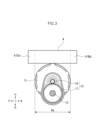
- FIG. 3 is a cross-sectional view taken along line III-III in FIG. 2 .
- FIG. 11 is a front view showing a motor and an inverter of a drive source according to a second embodiment of the present invention as viewed from the front.
- Fig. 1 shows the main parts of a saddle-type vehicle equipped with a drive source according to one embodiment of the present invention.
- this saddle-type vehicle 1 is equipped with a drive source 2 that outputs the drive force for traveling.
- the drive source 2 comprises, from top to bottom, a battery 3, an inverter 4 that converts DC power from the battery 3 into AC power, and a motor 5 that outputs rotational power using the power from the inverter 4.
- U, “D”, “F”, and “B” in Fig. 1 indicate that the directions of the corresponding arrows are "up”, “down”, “forward”, and “rear”, respectively. The same is true in Fig. 3.
- the battery 3, inverter 4, and motor 5 are mounted on the body frame 6 of the saddle-type vehicle 1.
- the drive source 2 is not held on the swing arm 8 that connects the body frame 6 and the rear wheel 7.
- the battery 3 and inverter 4 are positioned so that they at least partially overlap in the vertical direction.
- the inverter 4 and motor 5 are also positioned so that they at least partially overlap in the vertical direction.
- the inverter 4 has a protruding portion 9 that protrudes further than the motor 5 in the horizontal direction.
- the protruding portion 9 is disposed in a position that is directly exposed to the wind generated when the saddle-type vehicle 1 is traveling.
- a portion of the battery 3 is disposed inside the seat 10 of the saddle-type vehicle 1, as shown in FIG. 1.
- the protrusion 9 may be, for example, a forward protrusion that protrudes forward from the front end of the motor 5, a rearward protrusion that protrudes rearward from the rear end of the motor 5, a rightward protrusion that protrudes rightward from the right end of the motor 5 when viewed from the front, or a leftward protrusion that protrudes leftward from the left end of the motor 5.
- Figure 1 shows an example of an inverter 4 having a forward protrusion Fp and a rearward protrusion Bp.
- the protruding portion 9 (conceptually) includes a protruding portion 11 that protrudes horizontally beyond the battery 3.
- the protruding portion 11 may be a portion that protrudes forward, rearward, rightward, or leftward beyond the battery 3.
- a protruding portion Hf that protrudes forward beyond the battery 3 is shown.
- the protruding portion Hf has a forward protruding portion Fp that protrudes forward beyond the front end of the motor 5 described above.
- the protruding amount of the protruding portion Hf is greater than that of the forward protruding portion Fp.
- FIG. 2 shows the inverter 4 and motor 5 of the driving source 2 as seen from the front.
- FIG. 3 shows a cross section taken along line III-III in FIG. 2.
- the driving source 2 is equipped with an output shaft 12 that outputs the driving force for propelling the saddle-type vehicle 1 as rotational power, and a reducer 13 that reduces the rotational power of the rotating shaft of the motor 5 and transmits it to the output shaft 12.
- “U”, “D”, “L”, and “R” in FIG. 2 indicate that the directions of the corresponding arrows are “up”, “down”, “left”, and “right”, respectively. The same is true in FIG. 4.
- the inverter 4 includes a heat generating unit 14 having power transistors, which are heat generating elements such as MOSFETs and IGBTs, that perform switching when converting DC power from the battery 3 into AC power, and a control unit 15 having a microcomputer that controls the switching.
- the heat generating unit 14 having the heat generating element is provided on the protruding portion 9 of the inverter 4.
- Figure 2 shows an example in which the heat generating unit 14 is provided on the right protruding portion Rp.
- the reduction gear 13 includes a pinion gear 16 provided on the rotating shaft of the motor 5, and an output gear 17 fixed to the output shaft 12 and meshing with the pinion gear 16.
- a sprocket 18 is provided on the end of the output shaft 12.
- a roller chain 20 is stretched between the sprocket 18 and a sprocket 19 fixed to the rear wheel 7 of the saddle-type vehicle 1.
- the inverter 4 has a protruding portion 9 that protrudes horizontally beyond the motor 5, at a position where it comes into direct contact with the wind when the vehicle is running. This increases the heat dissipation surface of the inverter 4, allowing the wind to come into direct contact with the heat dissipation surface. Therefore, the inverter 4 can be effectively cooled by a simple, inexpensive configuration that only requires the provision of the protruding portion 9.
- the protrusion 9 may be a forward protrusion Fp, a rearward protrusion Bp, a rightward protrusion Rp, or a leftward protrusion, and these protrusions can be appropriately selected and set according to the arrangement of other parts of the saddle-type vehicle 1.
- the protrusion 9 includes a protrusion portion 11 that protrudes horizontally beyond the battery 3, which further increases the area of the heat dissipation surface of the inverter 4 and further improves the cooling effect of the inverter 4.
- the heating section 14 having a heating element is disposed on the protruding portion 9, the motor 5 and the heating element can be separated. This makes it difficult for the heat from the heating element to be transferred to the motor 5, so the high output of the motor 5 can be maintained without hindrance. In addition, since the heat from the motor 5 is difficult to transfer to the heating element, the function of the inverter 4 can also be maintained well.
- the entire range occupied by the reduction gear 13 is included within the range Ra occupied by the motor 5, so even if the reduction gear 13 is provided, the dimensions of the drive source 2 including the motor 5 and reduction gear 13 can be prevented from expanding in the fore-and-aft direction.
- the battery 3, inverter 4, and motor 5 are mounted on the body frame 6 of the saddle-type vehicle 1, the unsprung weight can be reduced compared to a conventional drive source in which the battery 3, inverter 4, and motor 5 are mounted on a swing arm 8 that functions as a suspension. This improves the dynamic performance of the saddle-type vehicle 1.
- FIG. 4 shows the motor 5 and inverter 4b of the drive source according to the second embodiment of the present invention, viewed from the front.
- the inverter 4b has fins 21 for heat dissipation provided on the underside of the right protrusion Rp.
- the fins 21 are provided so that the heat dissipation surface runs along the front-to-rear direction.
- the fin 21 is provided on the right protruding portion Rp, but if the inverter 4b has the above-mentioned forward protruding portion Fp, rearward protruding portion Bp, or left protruding portion, the fin 21 may be provided on these protruding portions. Also, if the inverter 4b has a protruding portion 11 that protrudes further than the battery 3, the fin 21 may be provided on the protruding portion 11.
- the inverter 4b has a larger heat dissipation surface area due to the fins 21 provided, compared to the inverter 4 in the first embodiment, so the inverter 4b can be cooled more effectively.
- Other points in this embodiment are the same as those in the first embodiment.
- the reduction gear 13 may have an intermediate gear between the pinion gear 16 and the output gear 17.
- the drive source 2 may be provided on the swing arm 8.
- the saddle-type vehicle 1 also includes scooter-type vehicles and other motorcycles.
Landscapes
- Engineering & Computer Science (AREA)
- Mechanical Engineering (AREA)
- Chemical & Material Sciences (AREA)
- Combustion & Propulsion (AREA)
- Transportation (AREA)
- Electric Propulsion And Braking For Vehicles (AREA)
Priority Applications (2)
| Application Number | Priority Date | Filing Date | Title |
|---|---|---|---|
| JP2025523170A JPWO2024247227A1 (de) | 2023-06-01 | 2023-06-01 | |
| PCT/JP2023/020499 WO2024247227A1 (ja) | 2023-06-01 | 2023-06-01 | 鞍乗型車両用駆動源 |
Applications Claiming Priority (1)
| Application Number | Priority Date | Filing Date | Title |
|---|---|---|---|
| PCT/JP2023/020499 WO2024247227A1 (ja) | 2023-06-01 | 2023-06-01 | 鞍乗型車両用駆動源 |
Publications (1)
| Publication Number | Publication Date |
|---|---|
| WO2024247227A1 true WO2024247227A1 (ja) | 2024-12-05 |
Family
ID=93657200
Family Applications (1)
| Application Number | Title | Priority Date | Filing Date |
|---|---|---|---|
| PCT/JP2023/020499 Ceased WO2024247227A1 (ja) | 2023-06-01 | 2023-06-01 | 鞍乗型車両用駆動源 |
Country Status (2)
| Country | Link |
|---|---|
| JP (1) | JPWO2024247227A1 (de) |
| WO (1) | WO2024247227A1 (de) |
Citations (7)
| Publication number | Priority date | Publication date | Assignee | Title |
|---|---|---|---|---|
| JP2012091595A (ja) * | 2010-10-25 | 2012-05-17 | Honda Motor Co Ltd | 鞍乗型電動車両 |
| JP2012100397A (ja) * | 2010-10-29 | 2012-05-24 | Honda Motor Co Ltd | 鞍乗り型車両 |
| WO2012085986A1 (ja) * | 2010-12-24 | 2012-06-28 | 川崎重工業株式会社 | 電動二輪車 |
| WO2012090241A1 (ja) * | 2010-12-27 | 2012-07-05 | 川崎重工業株式会社 | 鞍乗型電動車両 |
| JP2013071717A (ja) * | 2011-09-29 | 2013-04-22 | Honda Motor Co Ltd | 電動二輪車 |
| JP2016092899A (ja) * | 2014-10-30 | 2016-05-23 | スズキ株式会社 | 電動車両の駆動停止システム |
| WO2019186954A1 (ja) * | 2018-03-29 | 2019-10-03 | 本田技研工業株式会社 | 鞍乗型電動車両 |
-
2023
- 2023-06-01 JP JP2025523170A patent/JPWO2024247227A1/ja active Pending
- 2023-06-01 WO PCT/JP2023/020499 patent/WO2024247227A1/ja not_active Ceased
Patent Citations (7)
| Publication number | Priority date | Publication date | Assignee | Title |
|---|---|---|---|---|
| JP2012091595A (ja) * | 2010-10-25 | 2012-05-17 | Honda Motor Co Ltd | 鞍乗型電動車両 |
| JP2012100397A (ja) * | 2010-10-29 | 2012-05-24 | Honda Motor Co Ltd | 鞍乗り型車両 |
| WO2012085986A1 (ja) * | 2010-12-24 | 2012-06-28 | 川崎重工業株式会社 | 電動二輪車 |
| WO2012090241A1 (ja) * | 2010-12-27 | 2012-07-05 | 川崎重工業株式会社 | 鞍乗型電動車両 |
| JP2013071717A (ja) * | 2011-09-29 | 2013-04-22 | Honda Motor Co Ltd | 電動二輪車 |
| JP2016092899A (ja) * | 2014-10-30 | 2016-05-23 | スズキ株式会社 | 電動車両の駆動停止システム |
| WO2019186954A1 (ja) * | 2018-03-29 | 2019-10-03 | 本田技研工業株式会社 | 鞍乗型電動車両 |
Also Published As
| Publication number | Publication date |
|---|---|
| JPWO2024247227A1 (de) | 2024-12-05 |
Similar Documents
| Publication | Publication Date | Title |
|---|---|---|
| TWI383900B (zh) | 電動二輪機車 | |
| TWI397478B (zh) | Electric locomotive | |
| JP5167055B2 (ja) | 電気自動二輪車 | |
| JP4520341B2 (ja) | 電動パワーステアリング装置を備える不整地走行車両 | |
| JP2021062667A (ja) | 駆動ユニット、及び電動自転車 | |
| JPWO2019186946A1 (ja) | 鞍乗型電動車両 | |
| WO2023007971A1 (ja) | 電動車両 | |
| US20220032764A1 (en) | Series hybrid type straddled vehicle | |
| WO2019186952A1 (ja) | 鞍乗型電動車両 | |
| JPWO2020213590A5 (de) | ||
| WO2022162891A1 (ja) | 駆動ユニット、及び電動自転車 | |
| WO2024247227A1 (ja) | 鞍乗型車両用駆動源 | |
| JP5129713B2 (ja) | 電気自動二輪車 | |
| JP7422324B2 (ja) | 駆動ユニット、及び電動自転車 | |
| WO2022162892A1 (ja) | 駆動ユニット、及び電動自転車 | |
| CN115180054B (zh) | 具有至少两个车轮的机动车辆 | |
| JP6688825B2 (ja) | 車両 | |
| JP7646036B2 (ja) | 鞍乗り型車両 | |
| JP3324192B2 (ja) | 電動式スクータ型車両 | |
| CN112874675B (zh) | 跨乘型车辆 | |
| JP7766387B2 (ja) | 自走式電動車両および電動機ユニット | |
| JPWO2023127117A5 (ja) | 鞍乗り型車両 | |
| JP2021062669A (ja) | 駆動ユニット、及び電動自転車 | |
| JP2023015905A (ja) | 電動車両 | |
| JP7635288B2 (ja) | 冷却水配管の配置構造 |
Legal Events
| Date | Code | Title | Description |
|---|---|---|---|
| 121 | Ep: the epo has been informed by wipo that ep was designated in this application |
Ref document number: 23939701 Country of ref document: EP Kind code of ref document: A1 |
|
| ENP | Entry into the national phase |
Ref document number: 2025523170 Country of ref document: JP Kind code of ref document: A |
|
| WWE | Wipo information: entry into national phase |
Ref document number: 2025523170 Country of ref document: JP |
|
| WWE | Wipo information: entry into national phase |
Ref document number: 202547091485 Country of ref document: IN |
|
| WWP | Wipo information: published in national office |
Ref document number: 202547091485 Country of ref document: IN |
|
| NENP | Non-entry into the national phase |
Ref country code: DE |