WO2024247687A1 - 蛍光体および発光装置 - Google Patents
蛍光体および発光装置 Download PDFInfo
- Publication number
- WO2024247687A1 WO2024247687A1 PCT/JP2024/017603 JP2024017603W WO2024247687A1 WO 2024247687 A1 WO2024247687 A1 WO 2024247687A1 JP 2024017603 W JP2024017603 W JP 2024017603W WO 2024247687 A1 WO2024247687 A1 WO 2024247687A1
- Authority
- WO
- WIPO (PCT)
- Prior art keywords
- phosphor
- light
- wavelength
- light emitting
- emitting device
- Prior art date
- Legal status (The legal status is an assumption and is not a legal conclusion. Google has not performed a legal analysis and makes no representation as to the accuracy of the status listed.)
- Ceased
Links
Images

Classifications
-
- C—CHEMISTRY; METALLURGY
- C09—DYES; PAINTS; POLISHES; NATURAL RESINS; ADHESIVES; COMPOSITIONS NOT OTHERWISE PROVIDED FOR; APPLICATIONS OF MATERIALS NOT OTHERWISE PROVIDED FOR
- C09K—MATERIALS FOR MISCELLANEOUS APPLICATIONS, NOT PROVIDED FOR ELSEWHERE
- C09K11/00—Luminescent materials, e.g. electroluminescent or chemiluminescent
- C09K11/08—Luminescent materials, e.g. electroluminescent or chemiluminescent containing inorganic luminescent materials
- C09K11/64—Luminescent materials, e.g. electroluminescent or chemiluminescent containing inorganic luminescent materials containing aluminium
-
- H—ELECTRICITY
- H10—SEMICONDUCTOR DEVICES; ELECTRIC SOLID-STATE DEVICES NOT OTHERWISE PROVIDED FOR
- H10H—INORGANIC LIGHT-EMITTING SEMICONDUCTOR DEVICES HAVING POTENTIAL BARRIERS
- H10H20/00—Individual inorganic light-emitting semiconductor devices having potential barriers, e.g. light-emitting diodes [LED]
- H10H20/80—Constructional details
- H10H20/85—Packages
- H10H20/851—Wavelength conversion means
Definitions
- the present invention relates to a phosphor and a light-emitting device.
- Phosphors are sometimes used industrially to form wavelength conversion members in light emitting devices, that is, members that convert light of a short wavelength into light of a long wavelength. With the recent widespread use of LEDs (light emitting diodes), phosphors have become increasingly important in industry.
- Patent Document 2 as Example 11, a phosphor having a design composition represented by Ce0.05Sr0.95Al2Si3O4N4 is described. Patent Document 2 also describes that when this phosphor is irradiated with excitation light having a peak wavelength of 340 nm , emission having a peak wavelength of 411 nm is observed.
- Patent Document 3 can be cited as a document that describes a phosphor having a chemical structure or chemical composition similar to the phosphors described in Patent Documents 1 and 2.
- the present invention has been made in consideration of these circumstances.
- One of the objects of the present invention is to provide a phosphor with good luminescence characteristics, such as external quantum efficiency.
- a phosphor represented by the general formula Ba a1 Sr a2 Ce b Al c Si d O e N f, in which the composition ratios a1, a2, b, c, d, e, and f have the following relationship when c+d 5:
- the phosphor according to any one of 1. to 9., The phosphor is a powder having a median diameter D50 of 10 to 50 ⁇ m. 11.
- a light emitting device comprising a light emitting element and the phosphor according to any one of 1. to 11. 13.
- the light-emitting device according to claim 12, The light emitting device, wherein the light emitting element is an LED element. 15. 12. The light emitting device according to any one of claims 12 to 14, A light-emitting device that is a lighting device or a signaling device.
- the present invention provides a phosphor with good luminescence properties, such as external quantum efficiency.
- FIG. 2 is a diagram showing X-ray diffraction spectra of phosphors of Examples and Comparative Examples.
- the phosphor of this embodiment is a phosphor represented by the general formula Ba a1 Sr a2 Ce b Al c Si d O e N f .
- the composition ratios a1, a2, b, c, d, e and f have the following relationship: a1>a2 0.70 ⁇ a1+a2+b ⁇ 1.20 0.001 ⁇ b ⁇ 0.20 1.50 ⁇ c ⁇ 2.50 2.50 ⁇ d ⁇ 3.50 3.05 ⁇ e ⁇ 6.50 2.75 ⁇ f ⁇ 4.40
- the peak wavelength of the fluorescence emitted is 412 to 420 nm.
- the inventors have found through their investigations that in the above composition and its neighboring compositions, the peak wavelength of the fluorescence emitted when irradiated with light having a wavelength of 350 nm seems to correlate with the magnitude of the external quantum efficiency. Based on this finding, the peak wavelength of the fluorescence emitted when irradiated with light having a wavelength of 350 nm was adopted as one of the design indicators. Specifically, the external quantum efficiency could be increased by designing a phosphor so that the peak wavelength of the fluorescence emitted when irradiated with light having a wavelength of 350 nm is 412 to 420 nm.
- the phosphor contains a large amount of foreign phases, impurities, fine powder, etc., which hinder the improvement of the external quantum efficiency, the presence of these substances causes the peak wavelength of the fluorescence to be outside the range of 412 to 420 nm (often exceeding 420 nm).
- the peak wavelength of the fluorescence is thought to be within the range of 412 to 420 nm.
- the phosphor of this embodiment can be manufactured by using appropriate raw materials in an appropriate ratio and through an appropriate manufacturing process.
- it is effective to optimize the selection and blending of raw materials, as well as the manufacturing conditions.
- the luminescence characteristics may be further improved by performing an acid treatment or classification treatment, which will be described later.
- the manufacturing conditions are inappropriate, a phosphor having the desired characteristics may not be obtained even if appropriate raw materials are used in the appropriate ratio.
- a1 is preferably 0.50 ⁇ a1 ⁇ 0.99, more preferably 0.70 ⁇ a1 ⁇ 0.99, further preferably 0.85 ⁇ a1 ⁇ 0.97, and particularly preferably 0.90 ⁇ a1 ⁇ 0.96.
- a2 is preferably 0 ⁇ a2 ⁇ 0.10, more preferably 0 ⁇ a2 ⁇ 0.05, and further preferably 0 ⁇ a2 ⁇ 0.02. a2 may be zero.
- b is preferably 0.001 ⁇ b ⁇ 0.15, and more preferably 0.003 ⁇ b ⁇ 0.10.
- a1+a2+b 0.80 ⁇ a1+a2+b ⁇ 1.10 is preferable, and 0.90 ⁇ a1+a2+b ⁇ 1.00 is more preferable.
- c may be in the range of 1.50 ⁇ c ⁇ 2.50, but is preferably in the range of 1.70 ⁇ c ⁇ 2.30, more preferably 1.80 ⁇ c ⁇ 2.20, and even more preferably 1.90 ⁇ c ⁇ 2.10.
- d may be in the range of 2.50 ⁇ d ⁇ 3.50, but is preferably in the range of 2.70 ⁇ d ⁇ 3.30, more preferably 2.80 ⁇ d ⁇ 3.20, and even more preferably 2.90 ⁇ d ⁇ 3.10.
- e may be in the range of 3.05 ⁇ e ⁇ 6.50, but is preferably in the range of 4.00 ⁇ e ⁇ 6.50, more preferably 4.50 ⁇ e ⁇ 6.25, even more preferably 5.00 ⁇ e ⁇ 6.00, particularly preferably 5.00 ⁇ e ⁇ 5.80, and especially preferably 5.00 ⁇ e ⁇ 5.50.
- f may be in the range of 2.75 ⁇ f ⁇ 4.40, but is preferably in the range of 3.00 ⁇ f ⁇ 4.30, more preferably 3.00 ⁇ f ⁇ 4.00, and even more preferably 3.20 ⁇ f ⁇ 3.80.
- the relative magnitudes between the respective numerical values are preferably as follows: c/d: Preferably, 0.50 ⁇ c/d ⁇ 0.80, more preferably, 0.55 ⁇ c/d ⁇ 0.75, further preferably, 0.60 ⁇ c/d ⁇ 0.75, and particularly preferably, 0.62 ⁇ c/d ⁇ 0.73.
- e/f Preferably, 0.90 ⁇ e/f ⁇ 2.00, more preferably, 1.00 ⁇ e/f ⁇ 1.90, and even more preferably, 1.20 ⁇ e/f ⁇ 1.80.
- the phosphor of this embodiment generally does not substantially contain Eu, because, as described above, Ce is thought to act as the luminescence center in the phosphor of this embodiment.
- the phosphor of the present embodiment does not contain Eu.
- the phosphor of this embodiment may have a characteristic spectrum of emitted fluorescence due to its chemical composition, etc.
- the half width (full width at half maximum) of the fluorescence spectrum emitted when the phosphor of this embodiment is irradiated with light having a wavelength of 350 nm is preferably 75 to 130 nm, more preferably 75 to 100 nm, even more preferably 80 to 95 nm, and particularly preferably 80 to 90 nm.
- the internal quantum efficiency of the phosphor of this embodiment when irradiated with light having a wavelength of 350 nm is preferably 50 to 95%, more preferably 60 to 95%, and even more preferably 70 to 90%.
- the chromaticity x of the fluorescence emitted when the phosphor of this embodiment is irradiated with light having a wavelength of 350 nm in the XYZ color system is preferably 0.168 to 0.182, more preferably 0.170 to 0.180, and the chromaticity y of the fluorescence is preferably 0.095 to 0.135, more preferably 0.100 to 0.130.
- the phosphor of this embodiment Since the phosphor of this embodiment has an appropriate absorptance for light with a wavelength of 500 nm, the luminescence characteristics such as external quantum efficiency may be further improved.
- the absorptance of the phosphor of this embodiment for light with a wavelength of 500 nm is preferably 1 to 10%, more preferably 3 to 9%, further preferably 4 to 8%, and particularly preferably 4 to 7%.
- the phosphor of this embodiment generally has a crystal structure identical to or similar to that of a crystal of an inorganic compound represented by the general formula BaAl 2 Si 3 O 4 N 4.
- the phosphor of this embodiment can be considered as a solid solution in which part of Ba in the general formula BaAl 2 Si 3 O 4 N 4 is substituted with Ce or Sr.
- the X-ray diffraction spectrum of the phosphor of this embodiment has a peak at approximately the same position (2 ⁇ ) as the peak observed in the X-ray diffraction spectrum of a crystal of an inorganic compound represented by the general formula BaAl 2 Si 3 O 4 N 4 .
- the peak positions in the X-ray diffraction spectrum of a crystal of an inorganic compound represented by the general formula BaAl 2 Si 3 O 4 N 4 based on simulation are shown at the bottom of FIG.
- the ratio of the heterogeneous phase in the phosphor of this embodiment can be estimated.
- the heterogeneous phase refers to a phase that has a crystal structure different from the crystal structure of the inorganic compound represented by the general formula BaAl 2 Si 3 O 4 N 4 and does not contribute to or may adversely affect the light emission characteristics of the phosphor of this embodiment.
- the value of B/A is preferably 0.3 or less, more preferably 0.2 or less.
- the value of B/A is zero, but considering the manufacturing cost and the like, in reality, 0.01 to 0.3 is preferable, and 0.03 to 0.2 is more preferable.
- the phosphor of this embodiment has an appropriate diffuse reflectance for light with a wavelength of 700 nm or 800 nm, which may further improve the light emitting characteristics of the phosphor of this embodiment.
- the diffuse reflectance of light with a wavelength of 700 nm or 800 nm may also be related to the surface condition of the phosphor and the amount of heterogeneous phases in the phosphor that do not contribute to or may have a negative effect on the luminescence characteristics of the phosphor (diffuse reflectance may also change depending on the conditions of acid treatment or elutriation treatment in the manufacture of the phosphor).
- the diffuse reflectance of the phosphor of this embodiment for light with a wavelength of 700 nm is preferably 92 to 98%, and more preferably 93 to 97%.
- the diffuse reflectance of the phosphor of this embodiment for light with a wavelength of 800 nm is preferably 92 to 98%, and more preferably 93 to 97%.
- the phosphor of this embodiment is typically in a powder form, or in other words, an aggregate of phosphor particles.
- the particle size distribution can be adjusted, for example, by changing the pulverization conditions or the elutriation conditions in the phosphor manufacturing process described below.
- the powdered phosphor of this embodiment has a median diameter D 50 (cumulative 50% particle diameter on a volume basis determined by a laser diffraction/scattering method) of preferably 10 to 50 ⁇ m, and more preferably 10 to 40 nm.
- the powdered phosphor of this embodiment has a volume-based cumulative 10% particle diameter D 10 determined by a laser diffraction/scattering method of preferably 3 to 25 ⁇ m, and more preferably 5 to 20 ⁇ m.
- the powdered phosphor of this embodiment has a volume-based cumulative 90% particle diameter D 90 determined by a laser diffraction/scattering method of preferably 20 to 80 ⁇ m, and more preferably 25 to 70 ⁇ m.
- the value of (D 90 -D 10 )/D 50 is preferably 1.20 to 1.90, more preferably 1.30 to 1.80. This value indicates that the particle size distribution of the powdered phosphor is relatively sharp. A sharp particle size distribution means that the phosphor particles in the powdered phosphor are homogeneous at least in terms of particle size. This is expected to lead to stable light emission and to reduce the variation in light emission characteristics between product lots.
- the fact that the value of (D 90 -D 10 )/D 50 is not too large can also be said to represent that the ratio of coarse particles or phosphors with extremely small particle sizes (fine powder) in the powdered phosphor that do not contribute to improving the light emission characteristics or have a negative effect on the light emission characteristics is relatively small.
- the phosphor of this embodiment can be manufactured by using appropriate raw materials in an appropriate ratio and through an appropriate manufacturing process. If the raw materials used or their blending are inappropriate, or if the manufacturing conditions are inappropriate, a phosphor having good luminescence characteristics may not be manufactured. An example of a preferred manufacturing process will now be described.
- raw materials containing Ba, Eu, etc. are prepared.
- the raw materials are usually in powder form.
- raw materials containing Ba include BaAl 2 O 4 , BaCO 3 , BaO, Ba 2 N, and Ba 3 N 2.
- BaAl 2 O 4 is preferred from the viewpoint of further improving the performance of the phosphor that is finally produced.
- examples of raw materials containing Sr include SrAl2O4 , SrCO3 , SrO, Sr2N , and Sr3N2 .
- An example of a raw material containing Ce is CeO.
- An example of a raw material containing Si is Si 3 N 4 .
- An example of a raw material containing Al is Al2O3 .
- the prepared raw materials are weighed and thoroughly mixed to prepare a mixture.
- the amount (molar ratio) of each raw material is an appropriate amount calculated backwards from the values of a1, a2, b, c, d, e, and f in the general formula described above. It is preferable to pass the mixture through a sieve to ensure uniform mixing and remove coarse particles.
- the above mixture is filled into a heat-resistant container (preferably a boron nitride container) and heated to form a fired product.
- the firing temperature is preferably 1500 to 1800°C, more preferably 1500 to 1700°C.
- the firing time (the time for maintaining the above temperature) is preferably 1 to 12 hours, more preferably 2 to 8 hours.
- the firing is preferably carried out in an atmosphere of an inert gas such as nitrogen gas, and the gas pressure is preferably about 0.01 to 0.1 MPa ⁇ G.
- the phosphor (calcined product) obtained by firing is usually in a lump form. Therefore, it is preferable to crush it appropriately.
- a pulverization process may be performed to adjust the particle size.
- a jet mill can be used for pulverization.
- annealing By heating (annealing) the phosphor obtained by firing (fired product) at the same heating temperature as the firing or at a lower temperature, it is possible to further improve the performance of the phosphor, such as its luminescence characteristics. Although the details are unknown, it is assumed that annealing homogenizes and reconstructs the crystal structure in the phosphor.
- the annealing is preferably carried out by placing the phosphor (fired product) in a heat-resistant container, preferably a boron nitride container.
- the annealing temperature is preferably 1400 to 1550°C, and more preferably 1450 to 1550°C.
- the annealing time (the time for which the temperature is maintained) is preferably 2 to 24 hours, more preferably 4 to 12 hours.
- the annealing is preferably carried out in an atmosphere of an inert gas such as nitrogen gas, with the gas pressure preferably being about 0.01 to 0.1 MPa ⁇ G.
- the phosphor of this embodiment is preferably subjected to an acid treatment.
- the acid treatment can be performed, for example, by immersing the phosphor in an acid aqueous solution and stirring appropriately.
- the acid treatment may remove or reduce foreign matter on the phosphor surface or a different phase that does not contribute to fluorescence or has a negative effect on the light emission characteristics. In other words, the acid treatment may further improve the characteristics of the phosphor.
- the light absorptance or diffuse reflectance of the phosphor may change.
- the acid aqueous solution may be an aqueous solution containing one or more acids selected from hydrofluoric acid, sulfuric acid, phosphoric acid, hydrochloric acid, and nitric acid.
- the acid treatment can be carried out by stirring the phosphor in an aqueous acid solution for a few minutes to a few hours (for example, 10 minutes to 6 hours).
- a known stirrer or the like can be used for stirring.
- a magnetic stirrer is preferably used.
- the temperature during stirring is, for example, 50 to 100°C, preferably 65 to 85°C (the liquid is maintained at this temperature).
- the stirring time is, for example, 1 minute to 2 hours, preferably about 10 minutes to 1 hour.
- the stirring speed depends on the scale of the stirring device, but is, for example, 300 to 600 rpm, preferably 350 to 500 rpm on a laboratory scale. Stirring at a relatively high speed applies a strong shear force to the phosphor, making it possible to more effectively remove foreign matter and heterogeneous phases, and thus a further improvement in the performance of the phosphor can be expected.
- After the acid treatment it is desirable to appropriately perform filtration, washing with water, drying, etc.
- Classification (preferably by elutriation)
- elutriation In order to reduce the amount of phosphors (fine powders) with extremely small particle sizes that do not contribute to improving the luminescence characteristics or that adversely affect the luminescence characteristics in the powdered phosphor, it is preferable to perform classification.
- classification There are various specific methods for classification, but in this embodiment, it is preferable to perform classification by elutriation.
- the classification point can be found by calculation based on Stokes' equation or by several trial experiments.
- the elutriation treatment can be preferably carried out by dispersing the powdered phosphor in an aqueous solution of sodium hexametaphosphate or water to prepare a dispersion, allowing the dispersion to stand, and then removing the supernatant.
- Other specific methods for classification can be appropriately applied by known methods.
- a light emitting device can be configured by combining the above phosphor with a light emitting element. Specifically, the light emitting element emits light capable of exciting the phosphor, and the above phosphor emits fluorescence upon receiving the light emitted from the light emitting element.
- the phosphor is usually encapsulated with an encapsulant and incorporated into the light emitting device in the form of a wavelength conversion member.
- the light-emitting element is preferably a light-emitting element that emits light with a wavelength of 300 to 400 nm, and more preferably a light-emitting element that emits light with a wavelength of 345 to 385 nm.
- the light emitting element is preferably an LED element.
- the application of the light emitting device of this embodiment is not particularly limited.
- the light emitting device of this embodiment can be applied, for example, to backlights for liquid crystal display devices, light source devices for projectors, lighting devices, traffic lights, and the like.
- the light emitting device of this embodiment is considered to be preferable as a lamp for indicating autonomous driving (an indicator light for indicating to the outside of the vehicle that the vehicle is in autonomous driving). This is because the light emitted from the light emitting device of this embodiment can conform to the characteristics (chromaticity x, y, etc.) of lamps for indicating autonomous driving proposed by SAE International (Society of Automotive Engineers).
- the light emitting device of this embodiment can be preferably applied to a light source for inspection.
- halogen lamps with a broad emission spectrum have been used as light sources for industrial inspection.
- an LED that includes a phosphor that emits fluorescence with a broad spectrum when excited as a wavelength conversion member.
- the spectrum of the fluorescence emitted when the phosphor of this embodiment is excited with light having a wavelength of 300 to 400 nm is relatively broad and flat in the wavelength region of 400 nm or slightly longer. Therefore, a light-emitting device constructed by combining the phosphor of this embodiment with a light-emitting element meets the above-mentioned objectives.
- the phosphor was produced as follows. (1) Weighing and mixing of raw materials Each raw material was weighed according to the mass ratio shown in Table 1 below. All of the weighed raw materials were placed in a polyethylene bag with a zipper, the zipper of the bag was closed, and the bag was shaken for 1 minute. In this way, a mixture of raw materials was obtained. The obtained mixture was sieved through a #100 sieve, and the mixture that passed through the sieve was used in the next step.
- composition analysis was carried out on some of the phosphors of Examples 1 to 5.
- the contents of Ba, Sr, Ce, Al and Si in the phosphor were quantitatively analyzed by dissolving the phosphor by a pressurized acid decomposition method and then using an ICP emission spectrometer (5110VDV manufactured by Agilent).
- compositions of the phosphors of Examples 2 and 3 are considered to be similar to that of Example 4, considering that the raw material compositions of Examples 2 and 3 are the same as those of Example 4, and that the manufacturing processes of Examples 2 and 3 are similar to that of Example 4.
- ⁇ Particle size distribution measurement> Using Microtrac SYNC (manufactured by Microtrac Bell Co., Ltd.), the measurement was performed by the laser diffraction scattering method in accordance with JIS R1629:1997. 0.2 g of phosphor powder was added to 80 mL of ion-exchanged water, and a dispersion process was performed for 90 seconds using a horn-type ultrasonic homogenizer (output 300 W, horn diameter 26 mm), and then the particle size distribution was measured using SYNC. From the obtained particle size distribution, the volume-based median diameter D50 and the like were obtained. The obtained values, such as D50, are shown in Table 4.
- the X-ray diffraction spectrum of the obtained sample was measured using an Ultima IV-N device manufactured by Rigaku Corporation.
- the peak intensity (maximum value) A in the range of 2 ⁇ from 25.0 to 26.0° and the peak intensity (maximum value) B in the range of 2 ⁇ from 29.0 to 30.0° were read, and the value of B/A was calculated.
- Figure 1 The obtained X-ray diffraction spectrum is shown in Figure 1.
- the lower part of Figure 1 also shows the positions of peaks in the X-ray diffraction spectrum of a crystal of an inorganic compound represented by the general formula BaAl 2 Si 3 O 4 N 4 based on simulation.
- the B/A value is shown in Table 5.
- the diffuse reflectance of light with a wavelength of 700 nm or 800 nm was measured using an integrating sphere device (ISV-469) attached to a JASCO UV-Visible Spectrophotometer (V-550). Specifically, baseline correction was first performed using a standard reflector (Spectralon). Then, a solid sample holder filled with phosphor powder was attached to a predetermined position, and the diffuse reflectance of light with wavelengths of 700 nm and 800 nm was measured.
- the absorptance (%) of light with a wavelength of 500 nm was calculated in the same manner as the ⁇ Performance evaluation> shown below (absorptance, internal quantum efficiency, and external quantum efficiency when irradiated with light with a wavelength of 350 nm) except that the wavelength of the irradiated light was 500 nm instead of 350 nm, and Qex and Qref were calculated from the spectrum with a wavelength range of 495 nm to 510 nm.
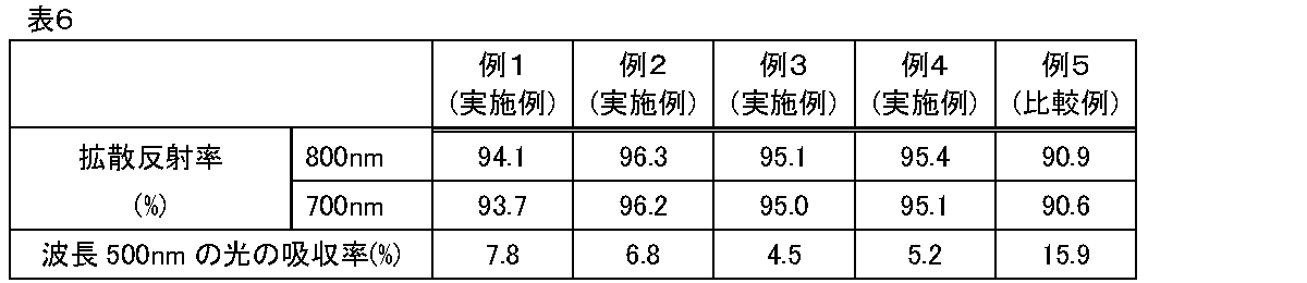
- the diffuse reflectance of light with a wavelength of 700 nm or 800 nm, and the absorptance of light with a wavelength of 500 nm are shown in Table 6.
- Monochromatic light which was split into 350 nm wavelengths from a light emission source (Xe lamp), was introduced into the integrating sphere using an optical fiber. This monochromatic light was irradiated onto the phosphor, and the fluorescence spectrum was measured.
- a standard reflector with a reflectance of 99% (Spectralon, manufactured by Labsphere) was attached to a predetermined position of the integrating sphere to measure the spectrum of excitation light with a wavelength of 350 nm. At that time, the number of excitation light photons (Qex) was calculated from the spectrum in the wavelength range of 345 nm to 360 nm.
- a cell filled with powdered phosphor was attached to a predetermined position of the integrating sphere, and the number of reflected excitation light photons (Qref) and the number of fluorescent photons (Qem) were calculated from the obtained spectrum data.
- the number of reflected excitation light photons was calculated in the same wavelength range as the number of excitation light photons, and the number of fluorescent photons was calculated in the range of 360 nm to 700 nm.
- the obtained Qex, Qref, and Qem were substituted into the following formula to determine the absorptance, internal quantum efficiency, and external quantum efficiency.
- the peak wavelength, half width, chromaticity x value, and chromaticity y value were determined.
- the chromaticity coordinates (x, y) were calculated according to the method in accordance with JIS Z 8724 (Method of measuring color-light source color-) and the calculation method in the XYZ color system defined in JIS Z 8701.
- the external quantum efficiency of the phosphors of Examples 1 to 4 was better than that of Example 5. That is, the phosphors represented by the general formula Ba a1 Sr a2 Ce b Al c Si d O e N f , which satisfied a1>a2, 0.70 ⁇ a1+a2+b ⁇ 1.20, 0.001 ⁇ b ⁇ 0.20, 1.50 ⁇ c ⁇ 2.50, 2.50 ⁇ d ⁇ 3.50, 3.05 ⁇ e ⁇ 6.50, and 2.75 ⁇ f ⁇ 4.40, and which emitted fluorescence with a peak wavelength of 412 to 420 nm when irradiated with light having a wavelength of 350 nm, exhibited good light-emitting properties. From the viewpoint of composition, such favorable light emission characteristics are believed to be due to the fact that the phosphor contains a relatively small amount of Ce, and the Ba content is relatively large compared to Sr, and so on.
- Example 5-1 A phosphor (Example 5-2) produced in the same manner as in Example 4, except that in the above ⁇ Production of phosphor>, (4) the annealing step, (5) the acid treatment and decantation, and (6) the elutriation classification were not carried out.
- Example 4-1 and 4-2 which did not undergo an annealing process or acid treatment, the various properties were different from those of Example 4.
- the peak wavelength of the fluorescence spectrum was over 520 nm.
- the B/A value determined by X-ray diffraction in Example 4-1 was large. From these, it can be seen that the luminescence properties can be optimized by appropriately reducing foreign phases, impurities, etc. through appropriate treatment after firing.
Landscapes
- Chemical & Material Sciences (AREA)
- Inorganic Chemistry (AREA)
- Engineering & Computer Science (AREA)
- Materials Engineering (AREA)
- Organic Chemistry (AREA)
- Luminescent Compositions (AREA)
Abstract
一般式Baa1Sra2CebAlcSidOeNfで示される蛍光体。この一般式において、c+d=5としたときの組成比a1、a2、b、c、d、eおよびfは、a1>a2、0.70≦a1+a2+b≦1.20、0.001≦b≦0.20、1.50≦c≦2.50、2.50≦d≦3.50、3.05≦e≦6.50および2.75≦f≦4.40を満たす。また、この蛍光体に波長350nmの光を照射したときに発せられる蛍光のピーク波長は412~420nmである。
Description
本発明は、蛍光体および発光装置に関する。
蛍光体は、産業上、発光装置における波長変換部材、つまり、短波長の光を長波長の光に変換する部材を構成するために用いられることがある。
近年のLED(発光ダイオード)の普及により、蛍光体は産業上ますます重要となってきている。
近年のLED(発光ダイオード)の普及により、蛍光体は産業上ますます重要となってきている。
特許文献1の請求項1には、一般式:MeaRebAlcSidOeNf(ただし、MeはSr及びBaから選ばれる一種以上の元素であり、ReはEuである。)で示される蛍光体であって、組成比a、b、c、d、eおよびfが次の関係を有する蛍光体が記載されている。
a+b=1
0.005<b<0.25
1.60<c<2.60
2.45<d<4.05
3.05<e<5.00
2.75<f<4.40
a+b=1
0.005<b<0.25
1.60<c<2.60
2.45<d<4.05
3.05<e<5.00
2.75<f<4.40
また、特許文献2には、実施例11として、設計組成がCe0.05Sr0.95Al2Si3O4N4で表される蛍光体が記載されている。特許文献2には、この蛍光体にピーク波長が340nmの励起光を照射したときに、ピーク波長が411nmの発光が観測されたことも記載されている。
さらに、特許文献1および2に記載された蛍光体と類似する化学構造または化学組成を有する蛍光体が記載された文献として、特許文献3を挙げることができる。
本発明者らの予備的検討の結果、例えば特許文献1~3に記載されているような従来の蛍光体には、外部量子効率などの発光特性の点で改良の余地があった。
本発明はこのような事情に鑑みてなされたものである。本発明の目的の1つは、外部量子効率などの発光特性が良好な蛍光体を提供することである。
本発明者らは、以下に提供される発明を完成させ、上記課題を解決した。
1.
一般式Baa1Sra2CebAlcSidOeNfで示される蛍光体であって、c+d=5としたときの組成比a1、a2、b、c、d、eおよびfが次の関係を有し、
波長350nmの光を照射したときに発せられる蛍光のピーク波長が412~420nmである蛍光体。
a1>a2
0.70≦a1+a2+b≦1.20
0.001≦b≦0.20
1.50≦c≦2.50
2.50≦d≦3.50
3.05≦e≦6.50
2.75≦f≦4.40
2.
1.に記載の蛍光体であって、
0.50≦a1≦0.99である蛍光体。
3.
1.または2.に記載の蛍光体であって、
0≦a2≦0.10である蛍光体。
4.
1.~3.のいずれか1つに記載の蛍光体であって、
波長350nmの光を照射したときに発せられる蛍光のスペクトルの半値幅が75~130nmである蛍光体。
5.
1.~4.のいずれか1つに記載の蛍光体であって、
波長500nmの光の吸収率が1~10%である蛍光体。
6.
1.~5.のいずれか1つに記載の蛍光体であって、
波長350nmの光を照射したときの内部量子効率が50~90%である蛍光体。
7.
1.~6.のいずれか1つに記載の蛍光体であって、
当該蛍光体をX線回折測定することで得られるX線回折スペクトルにおいて、2θが25.0~26.0°の範囲内にあるピークの強度をAとし、2θが29.0~30.0°の範囲内にあるピークの強度をBとしたとき、B/Aの値が0.3以下である蛍光体。
8.
1.~7.のいずれか1つに記載の蛍光体であって、
波長700nmの光の拡散反射率が92~97%である蛍光体。
9.
1.~8.のいずれか1つに記載の蛍光体であって、
波長800nmの光の拡散反射率が92~97%である蛍光体。
10.
1.~9.のいずれか1つに記載の蛍光体であって、
メジアン径D50が10~50μmの粉末である蛍光体。
11.
1.~10.のいずれか1つに記載の蛍光体であって、
Euを実質的に含まない蛍光体。
12.
発光素子と、1.~11.のいずれか1つに記載の蛍光体と、を備える発光装置。
13.
12.に記載の発光装置であって、
前記発光素子が、波長300~400nmの発光を有する発光素子である発光装置。
14.
12.または13.に記載の発光装置であって、
前記発光素子が、LED素子である発光装置。
15.
12.~14.のいずれか1つに記載の発光装置であって、
照明装置または信号装置である発光装置。
一般式Baa1Sra2CebAlcSidOeNfで示される蛍光体であって、c+d=5としたときの組成比a1、a2、b、c、d、eおよびfが次の関係を有し、
波長350nmの光を照射したときに発せられる蛍光のピーク波長が412~420nmである蛍光体。
a1>a2
0.70≦a1+a2+b≦1.20
0.001≦b≦0.20
1.50≦c≦2.50
2.50≦d≦3.50
3.05≦e≦6.50
2.75≦f≦4.40
2.
1.に記載の蛍光体であって、
0.50≦a1≦0.99である蛍光体。
3.
1.または2.に記載の蛍光体であって、
0≦a2≦0.10である蛍光体。
4.
1.~3.のいずれか1つに記載の蛍光体であって、
波長350nmの光を照射したときに発せられる蛍光のスペクトルの半値幅が75~130nmである蛍光体。
5.
1.~4.のいずれか1つに記載の蛍光体であって、
波長500nmの光の吸収率が1~10%である蛍光体。
6.
1.~5.のいずれか1つに記載の蛍光体であって、
波長350nmの光を照射したときの内部量子効率が50~90%である蛍光体。
7.
1.~6.のいずれか1つに記載の蛍光体であって、
当該蛍光体をX線回折測定することで得られるX線回折スペクトルにおいて、2θが25.0~26.0°の範囲内にあるピークの強度をAとし、2θが29.0~30.0°の範囲内にあるピークの強度をBとしたとき、B/Aの値が0.3以下である蛍光体。
8.
1.~7.のいずれか1つに記載の蛍光体であって、
波長700nmの光の拡散反射率が92~97%である蛍光体。
9.
1.~8.のいずれか1つに記載の蛍光体であって、
波長800nmの光の拡散反射率が92~97%である蛍光体。
10.
1.~9.のいずれか1つに記載の蛍光体であって、
メジアン径D50が10~50μmの粉末である蛍光体。
11.
1.~10.のいずれか1つに記載の蛍光体であって、
Euを実質的に含まない蛍光体。
12.
発光素子と、1.~11.のいずれか1つに記載の蛍光体と、を備える発光装置。
13.
12.に記載の発光装置であって、
前記発光素子が、波長300~400nmの発光を有する発光素子である発光装置。
14.
12.または13.に記載の発光装置であって、
前記発光素子が、LED素子である発光装置。
15.
12.~14.のいずれか1つに記載の発光装置であって、
照明装置または信号装置である発光装置。
本発明によれば、外部量子効率などの発光特性が良好な蛍光体が提供される。
以下、本発明の実施形態について、図面を参照しつつ、詳細に説明する。
本明細書中、数値範囲の説明における「X~Y」との表記は、特に断らない限り、X以上Y以下のことを表す。例えば、「1~5質量%」とは「1質量%以上5質量%以下」を意味する。
本明細書中、数値範囲の説明における「X~Y」との表記は、特に断らない限り、X以上Y以下のことを表す。例えば、「1~5質量%」とは「1質量%以上5質量%以下」を意味する。
<蛍光体>
本実施形態の蛍光体は、一般式Baa1Sra2CebAlcSidOeNfで示される蛍光体である。
この一般式において、c+d=5としたときの組成比a1、a2、b、c、d、eおよびfは、次の関係を有する。
a1>a2
0.70≦a1+a2+b≦1.20
0.001≦b≦0.20
1.50≦c≦2.50
2.50≦d≦3.50
3.05≦e≦6.50
2.75≦f≦4.40
本実施形態の蛍光体は、一般式Baa1Sra2CebAlcSidOeNfで示される蛍光体である。
この一般式において、c+d=5としたときの組成比a1、a2、b、c、d、eおよびfは、次の関係を有する。
a1>a2
0.70≦a1+a2+b≦1.20
0.001≦b≦0.20
1.50≦c≦2.50
2.50≦d≦3.50
3.05≦e≦6.50
2.75≦f≦4.40
また、本実施形態の蛍光体に、波長350nmの光を照射したときに発せられる蛍光のピーク波長は、412~420nmである。
本実施形態の蛍光体については、組成の観点では、比較的少量のCeを含む点が特徴の1つである。過去の知見に基づけば、この比較的少量のCeは発光中心として機能すると考えられる。
また、組成の観点では、a1>a2である、つまり、Srに比べてBaが比較的多く含まれること、および、a1>a2であることにより自動的にa1>0であり、組成中にBaが必ず含まれること(a2=0であり得るため)も、特徴的である。
詳細は不明であるが、発光中心であるCeと、それをとりまくBaなどの他元素の存在比率が適当であることが、本実施形態の蛍光体の良好な外部量子効率につながっている可能性がある。
また、組成の観点では、a1>a2である、つまり、Srに比べてBaが比較的多く含まれること、および、a1>a2であることにより自動的にa1>0であり、組成中にBaが必ず含まれること(a2=0であり得るため)も、特徴的である。
詳細は不明であるが、発光中心であるCeと、それをとりまくBaなどの他元素の存在比率が適当であることが、本実施形態の蛍光体の良好な外部量子効率につながっている可能性がある。
また、本発明者は、検討を通じ、上記組成のおよびその周辺の組成において、波長350nmの光を照射したときに発せられる蛍光のピーク波長が、外部量子効率の大きさと相関しているらしいことを知見した。この知見に基づき、波長350nmの光を照射したときに発せられる蛍光のピーク波長を設計指標の1つとして採用した。そして、具体的には、波長350nmの光を照射したときに発せられる蛍光のピーク波長が412~420nmとなるように蛍光体を設計することで、外部量子効率を高めることができた。
詳細は不明であるが、外部量子効率の良化の妨げとなる異相、不純物、微粉などが蛍光体中に多く含まれる場合、これらの存在のために蛍光のピーク波長は412~420nmの範囲外となる(420nm超となることが多い)と推測される。これに対し、蛍光体中の異相、不純物、微粉などが少ない場合、蛍光のピーク波長は412~420nmの範囲内に収まると考えられる。
詳細は不明であるが、外部量子効率の良化の妨げとなる異相、不純物、微粉などが蛍光体中に多く含まれる場合、これらの存在のために蛍光のピーク波長は412~420nmの範囲外となる(420nm超となることが多い)と推測される。これに対し、蛍光体中の異相、不純物、微粉などが少ない場合、蛍光のピーク波長は412~420nmの範囲内に収まると考えられる。
本実施形態の蛍光体は、適切な原料を適切な比率で用い、適切な製造プロセスを経ることで製造することができる。良好な発光特性を有する蛍光体を得るためには、原料の選択および配合の最適化に加え、製造条件の最適化も効果的である。例えば、製造プロセスについては、後述する酸処理や分級処理を行うことで発光特性を一層向上できる場合がある。
一方、製造条件が不適切な場合、適切な原料を適切な比率で用いたとしても所望の特性を有する蛍光体を得られないこともあり得る。
一方、製造条件が不適切な場合、適切な原料を適切な比率で用いたとしても所望の特性を有する蛍光体を得られないこともあり得る。
本実施形態の蛍光体について説明を続ける。
(一般式)
一般式Baa1Sra2CebAlcSidOeNfにおいて、c+d=5としたときの組成比a1、a2、b、c、d、eおよびfの値については、それぞれ以下に記載の通りである。
一般式Baa1Sra2CebAlcSidOeNfにおいて、c+d=5としたときの組成比a1、a2、b、c、d、eおよびfの値については、それぞれ以下に記載の通りである。
a1、a2およびbについては、a1>a2、0.70≦a1+a2+b≦1.20かつ0.001≦b≦0.20であればよい。
特に良好な発光特性の観点から、a1については、好ましくは0.50≦a1≦0.99、より好ましくは0.70≦a1≦0.99、さらに好ましくは0.85≦a1≦0.97、特に好ましくは0.90≦a1≦0.96である。
特に良好な発光特性の観点から、a2については、好ましくは0≦a2≦0.10、より好ましくは0≦a2≦0.05、さらに好ましくは0≦a2≦0.02である。a2はゼロであってもよい。
特に良好な発光特性の観点から、bについては好ましくは0.001≦b≦0.15、より好ましくは0.003≦b≦0.10である。
a1+a2+bについては、好ましくは0.80≦a1+a2+b≦1.10、より好ましくは0.90≦a1+a2+b≦1.00である。
特に良好な発光特性の観点から、a1については、好ましくは0.50≦a1≦0.99、より好ましくは0.70≦a1≦0.99、さらに好ましくは0.85≦a1≦0.97、特に好ましくは0.90≦a1≦0.96である。
特に良好な発光特性の観点から、a2については、好ましくは0≦a2≦0.10、より好ましくは0≦a2≦0.05、さらに好ましくは0≦a2≦0.02である。a2はゼロであってもよい。
特に良好な発光特性の観点から、bについては好ましくは0.001≦b≦0.15、より好ましくは0.003≦b≦0.10である。
a1+a2+bについては、好ましくは0.80≦a1+a2+b≦1.10、より好ましくは0.90≦a1+a2+b≦1.00である。
cは、1.50≦c≦2.50であればよいが、好ましくは1.70≦c≦2.30、より好ましくは1.80≦c≦2.20、さらに好ましくは1.90≦c≦2.10である。
dは、2.50≦d≦3.50であればよいが、好ましくは2.70≦d≦3.30、より好ましくは2.80≦d≦3.20、さらに好ましくは2.90≦d≦3.10である。
eは、3.05≦e≦6.50であればよいが、好ましくは4.00≦e≦6.50、より好ましくは4.50≦e≦6.25、さらに好ましくは5.00≦e≦6.00、特に好ましくは5.00≦e≦5.80、とりわけ好ましくは5.00≦e≦5.50である。
fは、2.75≦f≦4.40であればよいが、好ましくは3.00≦f≦4.30、より好ましくは3.00≦f≦4.00、さらに好ましくは3.20≦f≦3.80である。
結晶構造の安定化などの観点から、各数値間の相対的な大きさについては、以下のとおりであることが好ましい。
c/d:
好ましくは0.50<c/d<0.80、より好ましくは0.55<c/d<0.75、さらに好ましくは0.60<c/d<0.75、特に好ましくは0.62<c/d<0.73
e/f:
好ましくは0.90<e/f<2.00、より好ましくは1.00<e/f<1.90、さらに好ましくは1.20<e/f<1.80
c/d:
好ましくは0.50<c/d<0.80、より好ましくは0.55<c/d<0.75、さらに好ましくは0.60<c/d<0.75、特に好ましくは0.62<c/d<0.73
e/f:
好ましくは0.90<e/f<2.00、より好ましくは1.00<e/f<1.90、さらに好ましくは1.20<e/f<1.80
本実施形態の蛍光体は、通常、Euを実質的に含まない。前述のように、本実施形態の蛍光体においては、Ceが発光中心として働くと考えられるためである。
「実質的に含まない」とは、具体的には、前述の一般式において、c+d=5としたときのEuの比率が、好ましくは0.001以下、より好ましくは0.0001以下であることをいう。
好ましくは、本実施形態の蛍光体はEuを含まない。
「実質的に含まない」とは、具体的には、前述の一般式において、c+d=5としたときのEuの比率が、好ましくは0.001以下、より好ましくは0.0001以下であることをいう。
好ましくは、本実施形態の蛍光体はEuを含まない。
(波長350nmの光を照射したときに発せられる蛍光について)
本実施形態の蛍光体は、化学組成などに起因して、発せられる蛍光のスペクトルが特徴的であり得る。
一例として、本実施形態の蛍光体に、波長350nmの光を照射したときに発せられる蛍光のスペクトルの半値幅(半値全幅)は、好ましくは75~130nm、より好ましくは75~100nm、さらに好ましくは80~95nm、特に好ましくは80~90nmである。
別観点として、本実施形態の蛍光体に、波長350nmの光を照射したときの内部量子効率は、好ましくは50~95%、より好ましくは60~95%、さらに好ましくは70~90%である。
さらに別の観点として、本実施形態の蛍光体に、波長350nmの光を照射したときに発せられる蛍光の、XYZ表色系における色度xは、好ましくは0.168~0.182、より好ましく0.170~0.180であり、また、色度yは、好ましくは0.095~0.135、より好ましくは0.100~0.130である。
本実施形態の蛍光体は、化学組成などに起因して、発せられる蛍光のスペクトルが特徴的であり得る。
一例として、本実施形態の蛍光体に、波長350nmの光を照射したときに発せられる蛍光のスペクトルの半値幅(半値全幅)は、好ましくは75~130nm、より好ましくは75~100nm、さらに好ましくは80~95nm、特に好ましくは80~90nmである。
別観点として、本実施形態の蛍光体に、波長350nmの光を照射したときの内部量子効率は、好ましくは50~95%、より好ましくは60~95%、さらに好ましくは70~90%である。
さらに別の観点として、本実施形態の蛍光体に、波長350nmの光を照射したときに発せられる蛍光の、XYZ表色系における色度xは、好ましくは0.168~0.182、より好ましく0.170~0.180であり、また、色度yは、好ましくは0.095~0.135、より好ましくは0.100~0.130である。
(波長500nmの光の吸収率)
本実施形態の蛍光体の、波長500nmの光の吸収率が適当であることにより、外部量子効率などの発光特性を一層高められる場合がある。
具体的には、本実施形態の蛍光体の、波長500nmの光の吸収率は、好ましくは1~10%、より好ましくは3~9%、さらに好ましくは4~8%、特に好ましくは4~7%である。
本実施形態の蛍光体の、波長500nmの光の吸収率が適当であることにより、外部量子効率などの発光特性を一層高められる場合がある。
具体的には、本実施形態の蛍光体の、波長500nmの光の吸収率は、好ましくは1~10%、より好ましくは3~9%、さらに好ましくは4~8%、特に好ましくは4~7%である。
(結晶構造およびX線回折スペクトル)
本発明者の知見によれば、本実施形態の蛍光体は、通常、一般式BaAl2Si3O4N4で表される無機化合物の結晶と同一または類似した結晶構造を有する。具体的には、本実施形態の蛍光体は、一般式BaAl2Si3O4N4におけるBaの一部が、CeまたはSrに置換固溶したものと捉えることができる。
上記結晶構造に起因して、本実施形態の蛍光体のX線回折スペクトルは、通常、一般式BaAl2Si3O4N4で表される無機化合物の結晶のX線回折スペクトルで観察されるピークの位置とほぼ同じ位置(2θ)に、ピークがある。
参考のため、シミュレーションに基づく、一般式BaAl2Si3O4N4で表される無機化合物の結晶のX線回折スペクトル中のピークの位置を、図1の一番下に示しておく。
本発明者の知見によれば、本実施形態の蛍光体は、通常、一般式BaAl2Si3O4N4で表される無機化合物の結晶と同一または類似した結晶構造を有する。具体的には、本実施形態の蛍光体は、一般式BaAl2Si3O4N4におけるBaの一部が、CeまたはSrに置換固溶したものと捉えることができる。
上記結晶構造に起因して、本実施形態の蛍光体のX線回折スペクトルは、通常、一般式BaAl2Si3O4N4で表される無機化合物の結晶のX線回折スペクトルで観察されるピークの位置とほぼ同じ位置(2θ)に、ピークがある。
参考のため、シミュレーションに基づく、一般式BaAl2Si3O4N4で表される無機化合物の結晶のX線回折スペクトル中のピークの位置を、図1の一番下に示しておく。
一般式BaAl2Si3O4N4で表される無機化合物の結晶のX線回折スペクトルと、本実施形態の蛍光体のX線回折スペクトルとを比較し、前者では表れていないが後者では表れている回折ピークを分析することで、本実施形態の蛍光体中の異相の比率を見積もりうる。ここで「異相」とは、一般式BaAl2Si3O4N4で表される無機化合物の結晶構造とは異なる結晶構造を有し、本実施形態の蛍光体の発光特性に寄与しないまたは悪影響を及ぼしうる相のことである。
具体的には、本実施形態の蛍光体をX線回折測定することで得られるX線回折スペクトルにおいて、2θが25.0~26.0°の範囲内にあるピークの強度をAとし、2θが29.0~30.0°の範囲内にあるピークの強度をBとしたとき、B/Aの値は、好ましくは0.3以下、より好ましくは0.2以下である。理想的にはB/Aの値はゼロであるが、製造コストなども考慮すると、現実的には0.01~0.3が好ましく、0.03~0.2がより好ましい。
具体的には、本実施形態の蛍光体をX線回折測定することで得られるX線回折スペクトルにおいて、2θが25.0~26.0°の範囲内にあるピークの強度をAとし、2θが29.0~30.0°の範囲内にあるピークの強度をBとしたとき、B/Aの値は、好ましくは0.3以下、より好ましくは0.2以下である。理想的にはB/Aの値はゼロであるが、製造コストなども考慮すると、現実的には0.01~0.3が好ましく、0.03~0.2がより好ましい。
(波長700nmまたは800nmの光の拡散反射率)
本実施形態の蛍光体の、波長700nmまたは800nmの光の拡散反射率は適当であることが好ましい、このことにより、本実施形態の蛍光体の発光特性などは一層向上する場合がある。
詳細は不明であるが、波長700nmまたは800nmの光の拡散反射率についても、蛍光体の表面状態や、蛍光体中の、蛍光体の発光特性に寄与しないまたは悪影響を及ぼしうる異相などの量に関係している可能性がある(拡散反射率も、例えば蛍光体の製造における酸処理や水簸処理の条件により変化しうる)。また、過去の知見によれば、発光に直接関係しない波長領域の拡散反射率の大きさと、母体結晶の結晶性の高さとの間には相関関係がある場合がある。結晶性が低いと発光(蛍光)を阻害しうるため、拡散反射率が大きく結晶性が高い方が良いと考えられる。これら推定理由により、波長700nmまたは800nmの光の拡散反射率を適切に調整することにより、蛍光体の発光特性などの性能を一層向上できると考えられる。
本実施形態の蛍光体の、波長700nmまたは800nmの光の拡散反射率は適当であることが好ましい、このことにより、本実施形態の蛍光体の発光特性などは一層向上する場合がある。
詳細は不明であるが、波長700nmまたは800nmの光の拡散反射率についても、蛍光体の表面状態や、蛍光体中の、蛍光体の発光特性に寄与しないまたは悪影響を及ぼしうる異相などの量に関係している可能性がある(拡散反射率も、例えば蛍光体の製造における酸処理や水簸処理の条件により変化しうる)。また、過去の知見によれば、発光に直接関係しない波長領域の拡散反射率の大きさと、母体結晶の結晶性の高さとの間には相関関係がある場合がある。結晶性が低いと発光(蛍光)を阻害しうるため、拡散反射率が大きく結晶性が高い方が良いと考えられる。これら推定理由により、波長700nmまたは800nmの光の拡散反射率を適切に調整することにより、蛍光体の発光特性などの性能を一層向上できると考えられる。
具体的には、本実施形態の蛍光体の、波長700nmの光の拡散反射率は、好ましくは92~98%、より好ましくは93~97%である。
また、本実施形態の蛍光体の、波長800nmの光の拡散反射率は、好ましくは92~98%、より好ましくは93~97%である。
また、本実施形態の蛍光体の、波長800nmの光の拡散反射率は、好ましくは92~98%、より好ましくは93~97%である。
(粒子径分布:メジアン径D50など)
本実施形態の蛍光体は、典型的には粉末状である。別の言い方として、本実施形態の蛍光体は、蛍光体粒子の集合体である。
粉末状である本実施形態の蛍光体の粒径分布が適当であることにより、発光特性などの諸性能の一層の向上を図ることができる場合がある。粒径分布は、例えば、後述する蛍光体の製造工程において、粉砕の条件や水簸処理の条件などを変えることで調整することができる。
本実施形態の蛍光体は、典型的には粉末状である。別の言い方として、本実施形態の蛍光体は、蛍光体粒子の集合体である。
粉末状である本実施形態の蛍光体の粒径分布が適当であることにより、発光特性などの諸性能の一層の向上を図ることができる場合がある。粒径分布は、例えば、後述する蛍光体の製造工程において、粉砕の条件や水簸処理の条件などを変えることで調整することができる。
具体的には、粉末状である本実施形態の蛍光体の、メジアン径D50(レーザー回折・散乱法により求められる体積基準の累積50%粒子径)は、好ましくは10~50μm、より好ましくは10~40nmである。
また、粉末状である本実施形態の蛍光体の、レーザー回折・散乱法により求められる、体積基準の累積10%粒子径D10は、好ましくは3~25μm、より好ましくは5~20μmである。
また、粉末状である本実施形態の蛍光体の、レーザー回折・散乱法により求められる、体積基準の累積90%粒子径D90は、好ましくは20~80μm、より好ましくは25~70μmである。
また、粉末状である本実施形態の蛍光体の、レーザー回折・散乱法により求められる、体積基準の累積10%粒子径D10は、好ましくは3~25μm、より好ましくは5~20μmである。
また、粉末状である本実施形態の蛍光体の、レーザー回折・散乱法により求められる、体積基準の累積90%粒子径D90は、好ましくは20~80μm、より好ましくは25~70μmである。
別観点として、(D90-D10)/D50の値は、好ましくは1.20~1.90、より好ましくは1.30~1.80である。この数値は、粉末状である蛍光体の粒径分布が比較的シャープであることを示す。粒径分布がシャープであるということは、粉末状である蛍光体中の蛍光体粒子が、少なくとも粒径の点で均質的であるということを意味する。そしてこのことは安定的な発光に繋がったり、製品ロット間での発光特性のばらつきを小さくすることに繋がったりすることが期待される。また、(D90-D10)/D50の値が大きすぎないということは、粉末状である蛍光体中の、発光特性の向上に寄与しないまたは発光特性に悪影響を及ぼす、粗大粒子や粒径が極めて小さい蛍光体(微粉)の比率が比較的少ないことを表すともいえる。
(蛍光体の製造方法)
本実施形態の蛍光体は、適切な原料を適当な比率で用い、適切な製造プロセスを経ることにより製造することができる。用いる原料やその配合が不適切であったり、製造条件が不適切であったりする場合には、良好な発光特性を有する蛍光体を製造できない場合がある。
以下、好ましい製造プロセスの一例を説明する。
本実施形態の蛍光体は、適切な原料を適当な比率で用い、適切な製造プロセスを経ることにより製造することができる。用いる原料やその配合が不適切であったり、製造条件が不適切であったりする場合には、良好な発光特性を有する蛍光体を製造できない場合がある。
以下、好ましい製造プロセスの一例を説明する。
・原料の準備
まず、Ba、Euなどを含む原料を準備する。原料は、通常、粉末状である。
Baを含む原料としては、BaAl2O4、BaCO3、BaO、Ba2N、Ba3N2などを挙げることができる。これらの中でも、最終的に製造される蛍光体の性能の一層の向上の観点からは、BaAl2O4が好ましい。
本実施形態の蛍光体がSrを含む場合、Srを含む原料としては、SrAl2O4、SrCO3、SrO、Sr2N、Sr3N2などを挙げることができる。
Ceを含む原料としては、CeOなどを挙げることができる。
Siを含む原料としては、Si3N4などを挙げることができる。
Alを含む原料としては、Al2O3などを挙げることができる。
まず、Ba、Euなどを含む原料を準備する。原料は、通常、粉末状である。
Baを含む原料としては、BaAl2O4、BaCO3、BaO、Ba2N、Ba3N2などを挙げることができる。これらの中でも、最終的に製造される蛍光体の性能の一層の向上の観点からは、BaAl2O4が好ましい。
本実施形態の蛍光体がSrを含む場合、Srを含む原料としては、SrAl2O4、SrCO3、SrO、Sr2N、Sr3N2などを挙げることができる。
Ceを含む原料としては、CeOなどを挙げることができる。
Siを含む原料としては、Si3N4などを挙げることができる。
Alを含む原料としては、Al2O3などを挙げることができる。
・原料の秤量および混合
準備した原料を秤量し、十分に混合して混合物とする。各原料の量(モル比)は、前述の一般式におけるa1、a2、b、c、d、eおよびfの値から逆算した適当な量とする。均一な混合や粗大粒子の除去のため、混合物は篩を通過させることが好ましい。
準備した原料を秤量し、十分に混合して混合物とする。各原料の量(モル比)は、前述の一般式におけるa1、a2、b、c、d、eおよびfの値から逆算した適当な量とする。均一な混合や粗大粒子の除去のため、混合物は篩を通過させることが好ましい。
・焼成
上記混合物を、耐熱性容器(好ましくは窒化ホウ素性容器)に充填し、加熱することで焼成物とする。
焼成の温度は、好ましくは1500~1800℃、より好ましくは1500~1700℃である。
焼成の時間(上記温度で維持する時間)は、好ましくは1~12時間、より好ましくは2~8時間である。
焼成は、窒素ガスなどの不活性ガス雰囲気下で行われることが好ましい。この際、ガスの圧力は0.01~0.1MPa・G程度とすることが好ましい。
上記混合物を、耐熱性容器(好ましくは窒化ホウ素性容器)に充填し、加熱することで焼成物とする。
焼成の温度は、好ましくは1500~1800℃、より好ましくは1500~1700℃である。
焼成の時間(上記温度で維持する時間)は、好ましくは1~12時間、より好ましくは2~8時間である。
焼成は、窒素ガスなどの不活性ガス雰囲気下で行われることが好ましい。この際、ガスの圧力は0.01~0.1MPa・G程度とすることが好ましい。
・解砕/粉砕
焼成して得られた蛍光体(焼成物)は、通常、塊状である。よって、適宜解砕することが好ましい。また、粒径の調整のために粉砕処理を施してもよい。粉砕には例えばジェットミルを用いることができる。
焼成して得られた蛍光体(焼成物)は、通常、塊状である。よって、適宜解砕することが好ましい。また、粒径の調整のために粉砕処理を施してもよい。粉砕には例えばジェットミルを用いることができる。
・アニール
焼成して得られた蛍光体(焼成物)に、焼成時の加熱温度かそれより低温での加熱(アニール)を施すことにより、蛍光体の発光特性などの性能を一層向上できる場合がある。詳細は不明であるが、アニールにより、蛍光体中の結晶構造の均質化、再構成などが起こっていると推測される。
アニールは、蛍光体(焼成物)を耐熱性容器に入れて行うことが好ましい。耐熱性容器としては、好ましくは窒化ホウ素性容器を挙げることができる。
アニールの温度は、好ましくは1400~1550℃、より好ましくは1450~1550℃である。
アニールの時間(上記温度で維持する時間)は、好ましくは2~24時間、より好ましくは4~12時間である。
アニールは、窒素ガスなどの不活性ガス雰囲気下で行われることが好ましい。この際、ガスの圧力は0.01~0.1MPa・G程度とすることが好ましい。
焼成して得られた蛍光体(焼成物)に、焼成時の加熱温度かそれより低温での加熱(アニール)を施すことにより、蛍光体の発光特性などの性能を一層向上できる場合がある。詳細は不明であるが、アニールにより、蛍光体中の結晶構造の均質化、再構成などが起こっていると推測される。
アニールは、蛍光体(焼成物)を耐熱性容器に入れて行うことが好ましい。耐熱性容器としては、好ましくは窒化ホウ素性容器を挙げることができる。
アニールの温度は、好ましくは1400~1550℃、より好ましくは1450~1550℃である。
アニールの時間(上記温度で維持する時間)は、好ましくは2~24時間、より好ましくは4~12時間である。
アニールは、窒素ガスなどの不活性ガス雰囲気下で行われることが好ましい。この際、ガスの圧力は0.01~0.1MPa・G程度とすることが好ましい。
・酸処理
本実施形態の蛍光体には、酸処理が施されることが好ましい。酸処理は、例えば、蛍光体を酸水溶液に浸漬し、適宜攪拌することにより行うことができる。酸処理により、蛍光体表面の異物や、蛍光に寄与しないまたは発光特性に悪影響を及ぼす異相を除去または低減できる場合がある。つまり、酸処理により蛍光体の特性を一層向上できる場合がある。ちなみに、酸処理で蛍光体表面の異物や異相が除去または低減された結果として、蛍光体の光吸収率や拡散反射率は変化する場合がある。
本実施形態の蛍光体には、酸処理が施されることが好ましい。酸処理は、例えば、蛍光体を酸水溶液に浸漬し、適宜攪拌することにより行うことができる。酸処理により、蛍光体表面の異物や、蛍光に寄与しないまたは発光特性に悪影響を及ぼす異相を除去または低減できる場合がある。つまり、酸処理により蛍光体の特性を一層向上できる場合がある。ちなみに、酸処理で蛍光体表面の異物や異相が除去または低減された結果として、蛍光体の光吸収率や拡散反射率は変化する場合がある。
酸水溶液としては、フッ化水素酸、硫酸、リン酸、塩酸、硝酸から選ばれる1種以上の酸を含む水溶液を用いることができる。
酸処理は、蛍光体を、数分から数時間程度(例えば10分から6時間)、酸水溶液中で撹拌することにより行うことができる。攪拌には公知のスターラ等を用いることができる。実験室においてはマグネチックスターラーを好ましく用いることができる。
攪拌時の温度は、例えば50~100℃、好ましくは65~85℃である(液体をこの温度に維持する)。攪拌の時間は、例えば1分~2時間、好ましくは10分~1時間程度である。攪拌速度は、撹拌装置のスケールにもよるが、実験室レベルのスケールでは、例えば300~600rpm、好ましくは350~500rpmである。比較的高速での撹拌により、蛍光体に強いせんだん力が加わるため、異物や異相をより一層強く除去することができ、ひいては蛍光体の一層の性能向上を期待することができる。
酸処理の後、適宜、ろ過、水洗、乾燥などを行うことが望ましい。また、酸処理後の蛍光体の回収に際しては、デカンテーション、吸引ろ過などを適切に行うことが好ましい。
酸処理は、蛍光体を、数分から数時間程度(例えば10分から6時間)、酸水溶液中で撹拌することにより行うことができる。攪拌には公知のスターラ等を用いることができる。実験室においてはマグネチックスターラーを好ましく用いることができる。
攪拌時の温度は、例えば50~100℃、好ましくは65~85℃である(液体をこの温度に維持する)。攪拌の時間は、例えば1分~2時間、好ましくは10分~1時間程度である。攪拌速度は、撹拌装置のスケールにもよるが、実験室レベルのスケールでは、例えば300~600rpm、好ましくは350~500rpmである。比較的高速での撹拌により、蛍光体に強いせんだん力が加わるため、異物や異相をより一層強く除去することができ、ひいては蛍光体の一層の性能向上を期待することができる。
酸処理の後、適宜、ろ過、水洗、乾燥などを行うことが望ましい。また、酸処理後の蛍光体の回収に際しては、デカンテーション、吸引ろ過などを適切に行うことが好ましい。
・分級(好ましくは水簸処理)
粉末状である蛍光体中の、発光特性の向上に寄与しないまたは発光特性に悪影響を及ぼす、粒径が極めて小さい蛍光体(微粉)の量を低減するため、分級を行うことが好ましい。分級には様々な具体的方法があり得るが、本実施形態においては水簸処理により分級を行うことが好ましい。分級を行う場合、分級点は、3~10μm程度に設定することが好ましい。ちなみに、水簸処理により分級を行う場合、分級点は、ストークスの式に基づく計算や、数回の試し実験により知ることができる。
水簸処理は、好ましくは、粉末状である蛍光体を、ヘキサメタリン酸Na水溶液または水に分散させて分散液を作り、そしてその分散液を静置し、その後に上澄み液を除去することにより行うことができる。その他、分級の具体的なやり方は公知の方法を適宜適用することができる。
粉末状である蛍光体中の、発光特性の向上に寄与しないまたは発光特性に悪影響を及ぼす、粒径が極めて小さい蛍光体(微粉)の量を低減するため、分級を行うことが好ましい。分級には様々な具体的方法があり得るが、本実施形態においては水簸処理により分級を行うことが好ましい。分級を行う場合、分級点は、3~10μm程度に設定することが好ましい。ちなみに、水簸処理により分級を行う場合、分級点は、ストークスの式に基づく計算や、数回の試し実験により知ることができる。
水簸処理は、好ましくは、粉末状である蛍光体を、ヘキサメタリン酸Na水溶液または水に分散させて分散液を作り、そしてその分散液を静置し、その後に上澄み液を除去することにより行うことができる。その他、分級の具体的なやり方は公知の方法を適宜適用することができる。
<発光装置>
上述の蛍光体と、発光素子とを組み合わせることで、発光装置を構成することができる。具体的には、蛍光体を励起させることが可能な光を発する発光素子と、その発光素子から発せられた光を受けて蛍光を発する上述の蛍光体と、により、発光装置を構成することができる。
蛍光体は、通常、封止材により封止されて、波長変換部材の形で発光装置中に組み込まれる。
上述の蛍光体と、発光素子とを組み合わせることで、発光装置を構成することができる。具体的には、蛍光体を励起させることが可能な光を発する発光素子と、その発光素子から発せられた光を受けて蛍光を発する上述の蛍光体と、により、発光装置を構成することができる。
蛍光体は、通常、封止材により封止されて、波長変換部材の形で発光装置中に組み込まれる。
上述の蛍光体の特性を鑑み、発光素子は、波長300~400nmの発光を有する発光素子であることが好ましく、波長345~385nmの発光を有する発光素子であることがより好ましい。
製造コストや種々の用途への適用を踏まえると、発光素子は、LED素子であることが好ましい。
製造コストや種々の用途への適用を踏まえると、発光素子は、LED素子であることが好ましい。
本実施形態の発光装置の適用用途は特に限定されない。本実施形態の発光装置は、例えば、液晶表示装置用バックライト、プロジェクタの光源装置、照明装置、信号装置などに適用可能である。その他、本実施形態の発光装置は自動運転表示用のランプ(自動車が自動運転中であることを車外に示すための表示灯)として好ましいと考えられる。これは、本実施形態の発光装置から発せられる光が、SAE International(Society of Automotive Engineers、米国自動車技術者協会)が提唱する、自動運転表示用のランプの特性(色度x、yなど)に適合しうるためである。
上記以外の用途として、本実施形態の発光装置は、検査用光源に好ましく適用可能と考えられる。
従来、工業的な検査用光源としては、ブロードな発光スペクトルを有するハロゲンランプが用いられてきた。そのブロードな発光スペクトルをLEDで再現するためには、励起されたときにブロードなスペクトルの蛍光を発する蛍光体を波長変換部材として備えるLEDを用いることが好ましい。
従来、工業的な検査用光源としては、ブロードな発光スペクトルを有するハロゲンランプが用いられてきた。そのブロードな発光スペクトルをLEDで再現するためには、励起されたときにブロードなスペクトルの蛍光を発する蛍光体を波長変換部材として備えるLEDを用いることが好ましい。
本実施形態の蛍光体を、波長300~400nmの光で励起したときに発せられる蛍光のスペクトルは、波長400nmかそれよりやや長波長の領域において、比較的ブロードで平坦である。よって、本実施形態の蛍光体と発光素子とを組み合わせて構成した発光装置は、上記目的に適う。
以上、本発明の実施形態について述べたが、これらは本発明の例示であり、上記以外の様々な構成を採用することができる。また、本発明は上述の実施形態に限定されるものではなく、本発明の目的を達成できる範囲での変形、改良等は本発明に含まれる。
本発明の実施態様を、実施例および比較例に基づき詳細に説明する。念のため述べておくと、本発明は実施例のみに限定されない。
<原料の準備>
以下の原料を準備した。
BaAl2O4:株式会社高純度化学研究所製
SrAl2O4:株式会社高純度化学研究所製
Si3N4:UBE株式会社製(品番:E10)
Al2O3:住友化学株式会社製(品番:AA-03)
CeO:信越化学工業株式会社製(品番:C)
以下の原料を準備した。
BaAl2O4:株式会社高純度化学研究所製
SrAl2O4:株式会社高純度化学研究所製
Si3N4:UBE株式会社製(品番:E10)
Al2O3:住友化学株式会社製(品番:AA-03)
CeO:信越化学工業株式会社製(品番:C)
<蛍光体の製造>
以下要領で蛍光体を製造した。
(1)原料の秤量および混合
各原料を、以下の表1に記載の質量比で秤量した。秤量した原料のすべてを、チャック付きのポリエチレン製の袋に入れ、袋のチャックを閉じ、1分間、袋を振った。このようにして原料の混合物を得た。得られた混合を#100の篩に通篩し、篩を通過した混合物を次工程に用いた。
以下要領で蛍光体を製造した。
(1)原料の秤量および混合
各原料を、以下の表1に記載の質量比で秤量した。秤量した原料のすべてを、チャック付きのポリエチレン製の袋に入れ、袋のチャックを閉じ、1分間、袋を振った。このようにして原料の混合物を得た。得られた混合を#100の篩に通篩し、篩を通過した混合物を次工程に用いた。

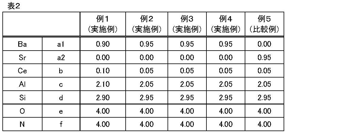
参考のため、上記組成の原料が完全に反応したと仮定した場合の、一般式Baa1Sra2CebAlcSidOeNfにおいてc+d=5としたときのa1、a2、b、c、d、eおよびfの値を表2に示す。
(2)焼成
(1)で得られた混合物およそ100gを、容量400ccの窒化ホウ素製容器(デンカ社製、N1グレード)に充填した。そして、以下条件で焼成した。
[焼成条件]
・焼成炉:富士電波工業社製の多目的焼成炉
・焼成温度と保持時間:例1および2は最高温度1650℃で4hr、例3~5は最高温度1550℃で4hr
・焼成雰囲気:N2 0.03MPa・G(N2)
(1)で得られた混合物およそ100gを、容量400ccの窒化ホウ素製容器(デンカ社製、N1グレード)に充填した。そして、以下条件で焼成した。
[焼成条件]
・焼成炉:富士電波工業社製の多目的焼成炉
・焼成温度と保持時間:例1および2は最高温度1650℃で4hr、例3~5は最高温度1550℃で4hr
・焼成雰囲気:N2 0.03MPa・G(N2)
(3)解砕/粉砕
焼成の終了後、容器内から、得られた焼成物を回収した。
そして、例1~3においては、乳鉢を用いて、♯200の篩を全通する程度に焼成物を解砕した。
一方、例4および5においては、乳鉢を用いて解砕し、その後、日本ニューマッチック工業社製の装置PJM-80SPを用い、試料供給速度:20g/min、粉砕エア圧:0.5MPaの条件でジェットミル粉砕を行った。
焼成の終了後、容器内から、得られた焼成物を回収した。
そして、例1~3においては、乳鉢を用いて、♯200の篩を全通する程度に焼成物を解砕した。
一方、例4および5においては、乳鉢を用いて解砕し、その後、日本ニューマッチック工業社製の装置PJM-80SPを用い、試料供給速度:20g/min、粉砕エア圧:0.5MPaの条件でジェットミル粉砕を行った。
(4)アニール工程
(3)の解砕/粉砕を経たサンプルを、容量400ccの窒化ホウ素製容器(デンカ社製、N1グレード)に充填した。その後、下記焼成条件でアニール処理を実施した。アニール処理後、室温まで自然冷却し、そして容器から焼成物を回収した。回収物は乳鉢を用いて♯200の篩を全通するように解砕した。
[アニール条件]
・焼成炉:富士電波工業社製の多目的焼成炉
・焼成温度と保持時間:1500℃で8hr
・焼成雰囲気:N2 0.03MPa・G(N2)
(3)の解砕/粉砕を経たサンプルを、容量400ccの窒化ホウ素製容器(デンカ社製、N1グレード)に充填した。その後、下記焼成条件でアニール処理を実施した。アニール処理後、室温まで自然冷却し、そして容器から焼成物を回収した。回収物は乳鉢を用いて♯200の篩を全通するように解砕した。
[アニール条件]
・焼成炉:富士電波工業社製の多目的焼成炉
・焼成温度と保持時間:1500℃で8hr
・焼成雰囲気:N2 0.03MPa・G(N2)
(5)酸処理およびデカンテーション
フッ素樹脂製ビーカーに、硝酸(60質量%、富士フイルム和光純薬社製)10mLとイオン交換水70mLを入れた。このビーカーを、ウォーターバスを用いて、ビーカー内の液体(酸水溶液)が60℃になるよう加熱した。
加熱された酸水溶液に、(4)でアニール処理し解砕されたサンプル約20gを入れ、30分間撹拌した。撹拌にはマグネチックスターラーを用いた。また、回転速度は400rpmに設定した。
撹拌終了後、ビーカーをウォーターバスから持ち上げて移動させ、約10分間静置した。その後、上澄み液を除去するデカンテーションの操作を計3回実施した。
デカンテーションを経て得られたスラリー状のサンプルを吸引濾過して回収した。そして、回収したサンプルを100℃×12hrの条件で乾燥させた。乾燥後のサンプルは#200のナイロン篩で通篩した。
フッ素樹脂製ビーカーに、硝酸(60質量%、富士フイルム和光純薬社製)10mLとイオン交換水70mLを入れた。このビーカーを、ウォーターバスを用いて、ビーカー内の液体(酸水溶液)が60℃になるよう加熱した。
加熱された酸水溶液に、(4)でアニール処理し解砕されたサンプル約20gを入れ、30分間撹拌した。撹拌にはマグネチックスターラーを用いた。また、回転速度は400rpmに設定した。
撹拌終了後、ビーカーをウォーターバスから持ち上げて移動させ、約10分間静置した。その後、上澄み液を除去するデカンテーションの操作を計3回実施した。
デカンテーションを経て得られたスラリー状のサンプルを吸引濾過して回収した。そして、回収したサンプルを100℃×12hrの条件で乾燥させた。乾燥後のサンプルは#200のナイロン篩で通篩した。
(6)分級(水簸処理)
事前に、ストークスの式に基づき、水簸処理を行う場合の、粒子径7μm以下の微粉を除去するために必要十分な蛍光体粉末の沈降時間を計算した。
上記計算に基づき、分散媒に分散させた上記(5)のサンプルを、容積500mLの棒瓶に入れ、所定時間静置した後、所定高さ以上の上澄み液を除去した。分散媒としては0.05質量%ヘキサメタリン酸ナトリウム水溶液を用いた。この操作は数回繰り返した。最終的に沈殿物として得られた粉末をろ過によって回収し、乾燥した。このようにして、乾燥した粉末状の蛍光体を得た。
事前に、ストークスの式に基づき、水簸処理を行う場合の、粒子径7μm以下の微粉を除去するために必要十分な蛍光体粉末の沈降時間を計算した。
上記計算に基づき、分散媒に分散させた上記(5)のサンプルを、容積500mLの棒瓶に入れ、所定時間静置した後、所定高さ以上の上澄み液を除去した。分散媒としては0.05質量%ヘキサメタリン酸ナトリウム水溶液を用いた。この操作は数回繰り返した。最終的に沈殿物として得られた粉末をろ過によって回収し、乾燥した。このようにして、乾燥した粉末状の蛍光体を得た。
<組成分析>
例1~5の蛍光体のうち一部について、組成分析を行った。
蛍光体中のBa、Sr、Ce、Al、Si含有率は、加圧酸分解法により蛍光体を溶解させた後、ICP発光分光分析装置(Agilent社製5110VDV)を用いて定量分析した。
また、蛍光体中のO、N含有率は、酸素窒素分析計装置(株式会社堀場製作所製、EMGA-920)を用いて定量分析した。」
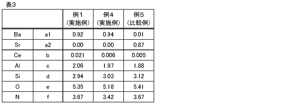
これら分析結果に基づき、一般式Baa1Sra2CebAlcSidOeNfにおいて、c+d=5としたときの組成比a1、a2、b、c、d、eおよびfを求めた。
組成分析の結果を表3に示す。
(附言:例2および3の蛍光体の組成分析は行わなかったが、例2および3の原料組成は例4と同じであること、および、例2および3の製造プロセスは例4と類似していることを踏まえれば、例2および3の蛍光体の組成は、例4と近似していると考えられる。)
例1~5の蛍光体のうち一部について、組成分析を行った。
蛍光体中のBa、Sr、Ce、Al、Si含有率は、加圧酸分解法により蛍光体を溶解させた後、ICP発光分光分析装置(Agilent社製5110VDV)を用いて定量分析した。
また、蛍光体中のO、N含有率は、酸素窒素分析計装置(株式会社堀場製作所製、EMGA-920)を用いて定量分析した。」
これら分析結果に基づき、一般式Baa1Sra2CebAlcSidOeNfにおいて、c+d=5としたときの組成比a1、a2、b、c、d、eおよびfを求めた。
組成分析の結果を表3に示す。
(附言:例2および3の蛍光体の組成分析は行わなかったが、例2および3の原料組成は例4と同じであること、および、例2および3の製造プロセスは例4と類似していることを踏まえれば、例2および3の蛍光体の組成は、例4と近似していると考えられる。)
<粒径分布測定>
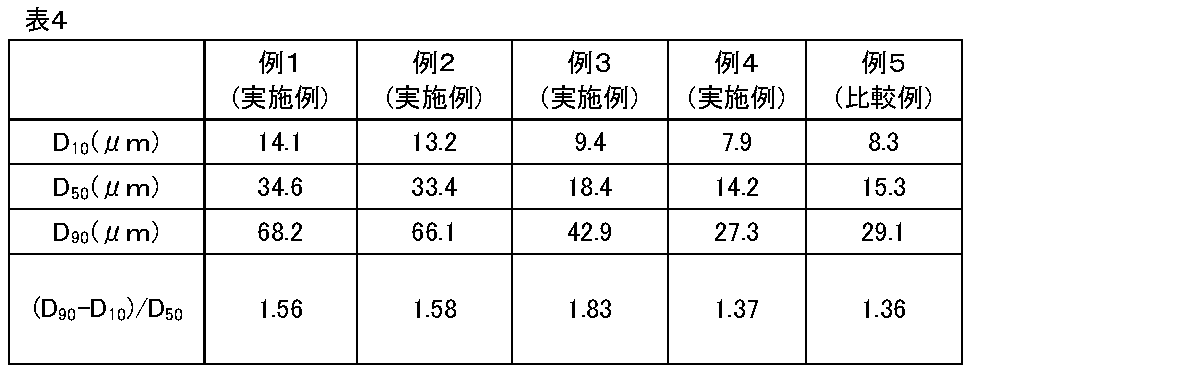
Microtrac SYNC(マイクロトラック・ベル株式会社製)を用い、JIS R1629:1997に準拠したレーザー回折散乱法により測定した。イオン交換水80mLに蛍光体粉末0.2gを投入し、そこにホーン式の超音波ホモジナイザー(出力300W、ホーン径26mm)で90秒間、分散処理を行い、その後、SYNCで粒径分布を測定した。得られた粒径分布から、体積基準のメジアン径D50などを求めた。
得られたD50などの値を表4に示す。
Microtrac SYNC(マイクロトラック・ベル株式会社製)を用い、JIS R1629:1997に準拠したレーザー回折散乱法により測定した。イオン交換水80mLに蛍光体粉末0.2gを投入し、そこにホーン式の超音波ホモジナイザー(出力300W、ホーン径26mm)で90秒間、分散処理を行い、その後、SYNCで粒径分布を測定した。得られた粒径分布から、体積基準のメジアン径D50などを求めた。
得られたD50などの値を表4に示す。
<X線回折測定>
得られたサンプルのX線回折スペクトルを測定した。測定にはRigaku社の装置Ultima IV―Nを用いた。
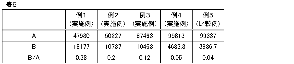
得られたX線回折スペクトルにおいて、2θが25.0~26.0°の範囲内にあるピークの強度(極大値)Aと、2θが29.0~30.0°の範囲内にあるピークの強度(極大値)Bの値を読み取った。そして、B/Aの値を計算した。
得られたサンプルのX線回折スペクトルを測定した。測定にはRigaku社の装置Ultima IV―Nを用いた。
得られたX線回折スペクトルにおいて、2θが25.0~26.0°の範囲内にあるピークの強度(極大値)Aと、2θが29.0~30.0°の範囲内にあるピークの強度(極大値)Bの値を読み取った。そして、B/Aの値を計算した。
得られたX線回折スペクトルを図1に示す。図1の下部には、参考のため、シミュレーションに基づく、一般式BaAl2Si3O4N4で表される無機化合物の結晶のX線回折スペクトル中のピークの位置も示している。
また、B/Aの値を表5に示す。
また、B/Aの値を表5に示す。
<波長700nmまたは800nmの光の拡散反射率、および、波長500nmの光の吸収率>
波長700nmまたは800nmの光の拡散反射率については、日本分光社製紫外可視分光光度計(V-550)に積分球装置(ISV-469)を取り付けて測定した。具体的には、まず、標準反射板(スペクトラロン)でベースライン補正を行った。その後、蛍光体粉末を充填した固体試料ホルダーを所定の位置に取り付けて、700nmおよび800nmの各波長の光に対する拡散反射率を測定した。
波長700nmまたは800nmの光の拡散反射率については、日本分光社製紫外可視分光光度計(V-550)に積分球装置(ISV-469)を取り付けて測定した。具体的には、まず、標準反射板(スペクトラロン)でベースライン補正を行った。その後、蛍光体粉末を充填した固体試料ホルダーを所定の位置に取り付けて、700nmおよび800nmの各波長の光に対する拡散反射率を測定した。
波長500nmの光の吸収率については、照射する光の波長を350nmではなく500nmとし、Qex、Qrefの算出は495nm以上510nm以下の波長範囲のスペクトルからを算出したこと以外は、以下に示す<性能評価>(波長350nmの光を照射したときの吸収率、内部量子効率および外部量子効率)と同様にして、波長500nmの光の吸収率(%)を求めた。
波長700nmまたは800nmの光の拡散反射率、および、波長500nmの光の吸収率を表6に示す。
<評価>
(波長350nmの光を照射したときの吸収率、内部量子効率および外部量子効率)
分光光度計(大塚電子株式会社製MCPD-7000)を用いて、蛍光体に波長350nmの光を照射したときの吸収率、内部量子効率および外部量子効率を求めた。具体的手順は以下のようにした。
(1)粉末状の蛍光体を、凹型セル内に充填した。このとき、充填した蛍光体の表面が平滑になるようにした。このセルを、積分球の所定の位置に取り付けた。この積分球に、発光光源(Xeランプ)から350nmの波長に分光した単色光を、光ファイバーを用いて導入した。この単色光を蛍光体に照射し、蛍光スペクトルを測定した。
(2)積分球の所定の位置に、反射率が99%の標準反射板(Labsphere社製スペクトラロン)を取り付けて、波長350nmの励起光のスペクトルを測定した。その際、345nm以上360nm以下の波長範囲のスペクトルから励起光フォトン数(Qex)を算出した。
(3)積分球の所定の位置に、粉末状の蛍光体を充填したセルを取り付けて、得られたスペクトルデータから励起反射光フォトン数(Qref)及び蛍光フォトン数(Qem)を算出した。励起反射光フォトン数は、励起光フォトン数と同じ波長範囲で、蛍光フォトン数は、360nm以上700nm以下の範囲で算出した。
(4)得られたQex、QrefおよびQemを以下式に代入して、吸収率、内部量子効率および外部量子効率を求めた。
吸収率=(Qex-Qref)/Qex
内部量子効率=Qem/(Qex-Qref)
外部量子効率=Qem/Qex
後掲の表7には、上記各値に100を掛けて%表記した値を記載した。
(波長350nmの光を照射したときの吸収率、内部量子効率および外部量子効率)
分光光度計(大塚電子株式会社製MCPD-7000)を用いて、蛍光体に波長350nmの光を照射したときの吸収率、内部量子効率および外部量子効率を求めた。具体的手順は以下のようにした。
(1)粉末状の蛍光体を、凹型セル内に充填した。このとき、充填した蛍光体の表面が平滑になるようにした。このセルを、積分球の所定の位置に取り付けた。この積分球に、発光光源(Xeランプ)から350nmの波長に分光した単色光を、光ファイバーを用いて導入した。この単色光を蛍光体に照射し、蛍光スペクトルを測定した。
(2)積分球の所定の位置に、反射率が99%の標準反射板(Labsphere社製スペクトラロン)を取り付けて、波長350nmの励起光のスペクトルを測定した。その際、345nm以上360nm以下の波長範囲のスペクトルから励起光フォトン数(Qex)を算出した。
(3)積分球の所定の位置に、粉末状の蛍光体を充填したセルを取り付けて、得られたスペクトルデータから励起反射光フォトン数(Qref)及び蛍光フォトン数(Qem)を算出した。励起反射光フォトン数は、励起光フォトン数と同じ波長範囲で、蛍光フォトン数は、360nm以上700nm以下の範囲で算出した。
(4)得られたQex、QrefおよびQemを以下式に代入して、吸収率、内部量子効率および外部量子効率を求めた。
吸収率=(Qex-Qref)/Qex
内部量子効率=Qem/(Qex-Qref)
外部量子効率=Qem/Qex
後掲の表7には、上記各値に100を掛けて%表記した値を記載した。
また、この測定で得られた蛍光スペクトルから、ピーク波長、半値幅、色度x値及び色度y値を求めた。
色度の求め方について補足しておくと、JIS Z 8724(色の測定方法-光源色-)に準じた方法で、JIS Z 8701に規定されるXYZ表色系における算出法により、色度座標(x、y)を算出した。
色度の求め方について補足しておくと、JIS Z 8724(色の測定方法-光源色-)に準じた方法で、JIS Z 8701に規定されるXYZ表色系における算出法により、色度座標(x、y)を算出した。
評価結果をまとめて表7に示す。

表7に示されるとおり、例1~4の蛍光体の外部量子効率は例5よりも良好であった。つまり、一般式Baa1Sra2CebAlcSidOeNfで示され、a1>a2、0.70≦a1+a2+b≦1.20、0.001≦b≦0.20、1.50≦c≦2.50、2.50≦d≦3.50、3.05≦e≦6.50、2.75≦f≦4.40を満たし、かつ、波長350nmの光を照射したときに発せられる蛍光のピーク波長が412~420nmである蛍光体は、良好な発光特性を示した。
このような良好な発光特性は、組成の観点では、蛍光体が比較的少量のCeを含むこと、Srに比べてBaの含有量が比較的多いこと、などに起因していると考えられる。
このような良好な発光特性は、組成の観点では、蛍光体が比較的少量のCeを含むこと、Srに比べてBaの含有量が比較的多いこと、などに起因していると考えられる。
<参考:製造プロセスの条件変更に伴う特性の変化>
参考のため、以下2つの蛍光体を製造した。そして、これら蛍光体の特性の測定・評価をして、例5の蛍光体と比較した。
(例5-1)
上記<蛍光体の製造>において、(4)アニール工程、(5)酸処理およびデカンテーションおよび(6)水簸分級を行わなかった以外は例4と同様にして製造した蛍光体
(例5-2)
上記<蛍光体の製造>において、(5)酸処理およびデカンテーションおよび(6)水簸分級を行わなかった以外は例4と同様にして製造した蛍光体
参考のため、以下2つの蛍光体を製造した。そして、これら蛍光体の特性の測定・評価をして、例5の蛍光体と比較した。
(例5-1)
上記<蛍光体の製造>において、(4)アニール工程、(5)酸処理およびデカンテーションおよび(6)水簸分級を行わなかった以外は例4と同様にして製造した蛍光体
(例5-2)
上記<蛍光体の製造>において、(5)酸処理およびデカンテーションおよび(6)水簸分級を行わなかった以外は例4と同様にして製造した蛍光体
結果をまとめて表8に示す。

表8から理解されるように、アニール工程や酸処理を行わなかった例4-1および4-2では、諸特性は例4と異なっていた。例えば、例4-1および4-2において、蛍光スペクトルのピーク波長は520nm超であった。また、例4-1のX線回折により求められるB/Aの値は大きかった。これらのことから、焼成後の適切な処理により、異相、不純物等を適切に低減することにより発光特性を最適化しうることが理解される。
この出願は、2023年5月26日に出願された日本出願特願2023-086764号を基礎とする優先権を主張し、その開示の全てをここに取り込む。
Claims (15)
- 一般式Baa1Sra2CebAlcSidOeNfで示される蛍光体であって、c+d=5としたときの組成比a1、a2、b、c、d、eおよびfが次の関係を有し、
波長350nmの光を照射したときに発せられる蛍光のピーク波長が412~420nmである蛍光体。
a1>a2
0.70≦a1+a2+b≦1.20
0.001≦b≦0.20
1.50≦c≦2.50
2.50≦d≦3.50
3.05≦e≦6.50
2.75≦f≦4.40 - 請求項1に記載の蛍光体であって、
0.50≦a1≦0.99である蛍光体。 - 請求項1または2に記載の蛍光体であって、
0≦a2≦0.10である蛍光体。 - 請求項1または2に記載の蛍光体であって、
波長350nmの光を照射したときに発せられる蛍光のスペクトルの半値幅が75~130nmである蛍光体。 - 請求項1または2に記載の蛍光体であって、
波長500nmの光の吸収率が1~10%である蛍光体。 - 請求項1または2に記載の蛍光体であって、
波長350nmの光を照射したときの内部量子効率が50~90%である蛍光体。 - 請求項1または2に記載の蛍光体であって、
当該蛍光体をX線回折測定することで得られるX線回折スペクトルにおいて、2θが25.0~26.0°の範囲内にあるピークの強度をAとし、2θが29.0~30.0°の範囲内にあるピークの強度をBとしたとき、B/Aの値が0.3以下である蛍光体。 - 請求項1または2に記載の蛍光体であって、
波長700nmの光の拡散反射率が92~97%である蛍光体。 - 請求項1または2に記載の蛍光体であって、
波長800nmの光の拡散反射率が92~97%である蛍光体。 - 請求項1または2に記載の蛍光体であって、
メジアン径D50が10~50μmの粉末である蛍光体。 - 請求項1または2に記載の蛍光体であって、
Euを実質的に含まない蛍光体。 - 発光素子と、請求項1または2に記載の蛍光体と、を備える発光装置。
- 請求項12に記載の発光装置であって、
前記発光素子が、波長300~400nmの発光を有する発光素子である発光装置。 - 請求項12に記載の発光装置であって、
前記発光素子が、LED素子である発光装置。 - 請求項12に記載の発光装置であって、
照明装置または信号装置である発光装置。
Priority Applications (1)
| Application Number | Priority Date | Filing Date | Title |
|---|---|---|---|
| JP2025523424A JPWO2024247687A1 (ja) | 2023-05-26 | 2024-05-13 |
Applications Claiming Priority (2)
| Application Number | Priority Date | Filing Date | Title |
|---|---|---|---|
| JP2023086764 | 2023-05-26 | ||
| JP2023-086764 | 2023-05-26 |
Publications (1)
| Publication Number | Publication Date |
|---|---|
| WO2024247687A1 true WO2024247687A1 (ja) | 2024-12-05 |
Family
ID=93657512
Family Applications (1)
| Application Number | Title | Priority Date | Filing Date |
|---|---|---|---|
| PCT/JP2024/017603 Ceased WO2024247687A1 (ja) | 2023-05-26 | 2024-05-13 | 蛍光体および発光装置 |
Country Status (3)
| Country | Link |
|---|---|
| JP (1) | JPWO2024247687A1 (ja) |
| TW (1) | TW202506962A (ja) |
| WO (1) | WO2024247687A1 (ja) |
Citations (4)
| Publication number | Priority date | Publication date | Assignee | Title |
|---|---|---|---|---|
| JP2011037913A (ja) * | 2009-08-06 | 2011-02-24 | Showa Denko Kk | 蛍光体及びその製造方法、並びにそれを用いた発光装置 |
| CN102181285A (zh) * | 2011-03-08 | 2011-09-14 | 中国科学技术大学 | 一种硅氧氮化物荧光粉及其制备方法 |
| WO2013069696A1 (ja) * | 2011-11-07 | 2013-05-16 | 独立行政法人物質・材料研究機構 | 蛍光体および製造方法、蛍光体を用いる発光装置および画像表示装置 |
| WO2015093429A1 (ja) * | 2013-12-17 | 2015-06-25 | 電気化学工業株式会社 | 蛍光体、発光装置及びその製造方法 |
-
2024
- 2024-05-13 WO PCT/JP2024/017603 patent/WO2024247687A1/ja not_active Ceased
- 2024-05-13 JP JP2025523424A patent/JPWO2024247687A1/ja active Pending
- 2024-05-22 TW TW113118844A patent/TW202506962A/zh unknown
Patent Citations (4)
| Publication number | Priority date | Publication date | Assignee | Title |
|---|---|---|---|---|
| JP2011037913A (ja) * | 2009-08-06 | 2011-02-24 | Showa Denko Kk | 蛍光体及びその製造方法、並びにそれを用いた発光装置 |
| CN102181285A (zh) * | 2011-03-08 | 2011-09-14 | 中国科学技术大学 | 一种硅氧氮化物荧光粉及其制备方法 |
| WO2013069696A1 (ja) * | 2011-11-07 | 2013-05-16 | 独立行政法人物質・材料研究機構 | 蛍光体および製造方法、蛍光体を用いる発光装置および画像表示装置 |
| WO2015093429A1 (ja) * | 2013-12-17 | 2015-06-25 | 電気化学工業株式会社 | 蛍光体、発光装置及びその製造方法 |
Also Published As
| Publication number | Publication date |
|---|---|
| JPWO2024247687A1 (ja) | 2024-12-05 |
| TW202506962A (zh) | 2025-02-16 |
Similar Documents
| Publication | Publication Date | Title |
|---|---|---|
| JP5368557B2 (ja) | β型サイアロン蛍光体、その用途及びその製造方法 | |
| TWI404792B (zh) | A phosphor and a method for manufacturing the same, and a light-emitting device using the same | |
| JP6572373B1 (ja) | β型サイアロン蛍光体の製造方法 | |
| JPWO2020054351A1 (ja) | 蛍光体及び発光装置 | |
| JPWO2020054350A1 (ja) | 蛍光体及び発光装置 | |
| JP2009096882A (ja) | 蛍光体とその製造方法 | |
| JPWO2014077240A1 (ja) | 蛍光体、発光素子及び照明装置 | |
| JP7045192B2 (ja) | 蛍光体および発光装置 | |
| JP7577660B2 (ja) | 蛍光体粒子の製造方法 | |
| JP2018002870A (ja) | β型サイアロン蛍光体とその製造方法及びそれを用いた発光装置 | |
| KR102936342B1 (ko) | 형광체 분말, 발광 장치, 화상 표시 장치 및 조명 장치 | |
| TW202225376A (zh) | 螢光體粉末、發光裝置、影像顯示裝置及照明裝置 | |
| WO2017155111A1 (ja) | 蛍光体、発光素子及び発光装置 | |
| JP5388699B2 (ja) | α型サイアロン蛍光体およびそれを用いた発光素子 | |
| JP7498171B2 (ja) | 表面被覆蛍光体粒子、及び発光装置 | |
| KR102924279B1 (ko) | 형광체 분말, 발광 장치, 화상 표시 장치 및 조명 장치 | |
| KR102923378B1 (ko) | 형광체 분말, 발광 장치, 화상 표시 장치 및 조명 장치 | |
| WO2024247685A1 (ja) | 蛍光体および発光装置 | |
| TW202506962A (zh) | 螢光體及發光裝置 | |
| WO2020235297A1 (ja) | α型サイアロン蛍光体、発光部材、および発光装置 | |
| JP2021054910A (ja) | 希土類アルミン酸塩蛍光体の製造方法、希土類アルミン酸塩蛍光体及び発光装置 | |
| TW202342698A (zh) | Eu賦活β型矽鋁氮氧化物螢光體粒子、β型矽鋁氮氧化物螢光體粉末及發光裝置 | |
| JP2024094873A (ja) | 蛍光体粉末の製造方法 | |
| JP2022136795A (ja) | ユウロピウム賦活β型サイアロン蛍光体、及び発光装置 |
Legal Events
| Date | Code | Title | Description |
|---|---|---|---|
| 121 | Ep: the epo has been informed by wipo that ep was designated in this application |
Ref document number: 24815171 Country of ref document: EP Kind code of ref document: A1 |
|
| ENP | Entry into the national phase |
Ref document number: 2025523424 Country of ref document: JP Kind code of ref document: A |
|
| NENP | Non-entry into the national phase |
Ref country code: DE |