WO2024252447A1 - 情報提示方法,情報提示システム、及びプログラム - Google Patents
情報提示方法,情報提示システム、及びプログラム Download PDFInfo
- Publication number
- WO2024252447A1 WO2024252447A1 PCT/JP2023/020764 JP2023020764W WO2024252447A1 WO 2024252447 A1 WO2024252447 A1 WO 2024252447A1 JP 2023020764 W JP2023020764 W JP 2023020764W WO 2024252447 A1 WO2024252447 A1 WO 2024252447A1
- Authority
- WO
- WIPO (PCT)
- Prior art keywords
- robot
- display screen
- unit
- telepresence robot
- person
- Prior art date
- Legal status (The legal status is an assumption and is not a legal conclusion. Google has not performed a legal analysis and makes no representation as to the accuracy of the status listed.)
- Ceased
Links
Images


Classifications
-
- G—PHYSICS
- G06—COMPUTING OR CALCULATING; COUNTING
- G06F—ELECTRIC DIGITAL DATA PROCESSING
- G06F3/00—Input arrangements for transferring data to be processed into a form capable of being handled by the computer; Output arrangements for transferring data from processing unit to output unit, e.g. interface arrangements
- G06F3/01—Input arrangements or combined input and output arrangements for interaction between user and computer
Definitions
- One aspect of the present invention relates to an information presentation method, an information presentation system, and a program for remote communication.
- Hybrid work is a work style that combines traditional office work, where people come to the office, with remote work from home or in a shared office. Remote communication is also becoming more common in stores and facilities in commercial spaces.
- Telepresence robots are attracting attention as a remote communication tool. Telepresence robots are robots that combine videoconferencing functions with remote control technology. Some telepresence robots have mobility capabilities. By using a physical device such as a telepresence robot, the person speaking to the robot can more easily sense the presence of the person operating the telepresence robot in a remote location.
- Non-Patent Document 1 shows an example of using a telepresence robot in an office space.
- Non-Patent Document 2 shows an example of using a telepresence robot in a commercial space (store).
- Non-Patent Document 3 shows the results of a survey on acceptability of robots.
- the present invention has been made in light of these points.
- the purpose of the present invention is to reduce psychological resistance to conversation with a robot in an information presentation method for remote communication using a robot.
- One aspect of the information presentation method is a method of presenting information using an information presentation system including a robot having a moving mechanism, a display screen, and a video calling function, and a remote control device for the robot, and includes displaying an audio waveform of audio acquired by the remote control device on the display screen, moving the robot to a first distance away from the person being spoken to while the audio waveform is displayed on the display screen, displaying a live-action video of the operator of the remote control device on the display screen, moving the robot to a position where the angle with respect to the person being spoken to is a first angle while the live-action video is displayed on the display screen, displaying an avatar of the operator on the display screen, and moving the robot to a second distance away from the position away from the person being spoken to that is shorter than the first distance while the avatar is displayed on the display screen.
- the information presentation method can control the display screen and the method of approaching a person when the telepresence robot approaches a person and attempts to converse with them in remote communication using a telepresence robot having a screen display function and a movement function. This can improve the person who is spoken to by the telepresence robot's acceptance of the telepresence robot.
- FIG. 1 is a block diagram showing an example of an overall configuration of an information presentation system according to an embodiment.
- FIG. 2 is a block diagram showing an example of a circuit configuration of a remote control device included in the information presentation system according to an embodiment.
- FIG. 3 is a block diagram showing an example of a circuit configuration of a telepresence robot included in an information presentation system according to an embodiment.
- FIG. 4 is a block diagram illustrating an example of a functional configuration of an information presentation system according to an embodiment.
- FIG. 5 is a diagram showing a specific example of a screen display on a display screen of a remote control device included in an information presentation system according to an embodiment.
- FIG. 6 is a diagram showing a specific example of a screen display on a display screen of a telepresence robot included in an information presentation system according to an embodiment.
- FIG. 7 is a diagram showing a specific example of a direction in which a telepresence robot included in an information presentation system according to an embodiment approaches a local speaker.
- FIG. 8 is a diagram showing a specific example of the moving direction of a telepresence robot and a screen display on a display screen when the telepresence robot included in an information presentation system according to an embodiment approaches a local speaker.
- FIG. 9 is a flowchart showing an overall flow of an information presentation method in an information presentation system according to an embodiment.
- Fig. 1 is a block diagram showing an example of an overall configuration of the information presentation system 1.
- the information presentation system 1 includes a remote control device 10 and a telepresence robot 20 (hereinafter simply referred to as "robot") that can communicate with the remote control device 10.
- robot a telepresence robot 20
- the location where the remote control device 10 is operated is referred to as the "remote location.”
- the location where the telepresence robot 20 is operating is referred to as the "local location.”
- the remote control device 10 is, for example, a personal computer.
- the remote control device 10 may be a tablet terminal such as a smartphone, or may be another computer device.
- the remote control device 10 has a function of remotely controlling the telepresence robot 20.
- the remote control device 10 also has a function of performing a video call (video chat) with the telepresence robot 20. For example, an image of the local area is displayed on the display screen 1000 of the remote control device 10.
- a person operating the remote control device 10 hereinafter referred to as "operator HM1" may operate the telepresence robot 20 via the remote control device 10.
- the operator HM1 operates the telepresence robot 20 to search for a person to talk to on-site, or to move the telepresence robot 20 closer to the person to talk to.
- the operator HM1 uses the video call function between the remote control device 10 and the telepresence robot 20 to talk to the person to be spoken to who is facing the telepresence robot 20 (hereinafter referred to as the "local speaker HM2").
- the telepresence robot 20 includes a moving mechanism 21, a support 22, and a video calling unit 23. Note that the telepresence robot 20 may be a mobile humanoid robot.
- the moving mechanism 21 moves the telepresence robot 20 based on the operation of the remote control device 10.
- the moving mechanism 21 includes a base, wheels, a motor for driving (rotating) the wheels, etc.
- the wheel drive motor (not shown) is installed in the base.
- two wheels are provided on the sides (left and right) of the cylindrical base. Separate wheel drive motors are attached to the two wheels. The two wheels are controlled independently of each other. By controlling the rotation of the left and right wheels, the telepresence robot 20 can run and turn.
- the configuration and arrangement of the base and wheels are not limited to this.
- the base may be a rectangular parallelepiped.
- three or more wheels may be provided.
- the support 22 is provided on the moving mechanism 21.
- a video calling unit 23 is provided on the support 22.
- the support 22 may be provided with an extension mechanism, and may also be provided with a rotation mechanism for rotating the video calling unit 23 (display screen 2000).
- the telepresence robot 20 may adjust the length of the support 22 to match the height of the local speaker HM2.
- the telepresence robot 20 may also change the orientation of the video calling unit 23 (display screen 2000) depending on the traveling direction of the moving mechanism 21 and the positional relationship with the local speaker HM2.
- the video call unit 23 is used for video calls.
- the video call unit 23 includes a display screen 2000.
- An image of a remote location (an image of the operator HM1) is displayed on the display screen 2000.
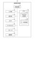
- Fig. 2 is a block diagram showing an example of the circuit configuration of the remote control device 10.
- the remote control device 10 includes a control circuit 11, a memory 12, an input unit 13, a display unit 14, a camera 15, a microphone 16, a speaker 17, and a communication unit 18. These are connected to each other so that they can transmit and receive data.
- the control circuit 11 is, for example, a CPU (Central Processing Unit).
- the control circuit 11 controls the entire remote control device 10.
- the control circuit 11 executes a program stored in the program storage section 121 of the memory 12.
- the memory 12 includes a program storage unit 121 and a data storage unit 122.
- the memory 12 may also include various types of storage devices as external storage, such as a magnetic disk storage device (HDD: Hard Disk Drive) or a solid state drive (SSD: Solid State Drive).
- HDD Hard Disk Drive
- SSD Solid State Drive
- the program storage unit 121 may be configured as a non-transient storage medium, for example, a non-volatile memory such as a ROM (Read Only Memory).
- the program storage unit 121 stores programs used to execute the information presentation system 1.
- the programs include an operation program for the telepresence robot 20 and a video call application with the telepresence robot 20.
- the data storage unit 122 may be configured as a storage medium, for example, a volatile memory such as a RAM (Random Access Memory).
- the data storage unit 122 stores data necessary for executing the information presentation system 1.
- the input unit 13 includes an input device such as a keyboard, a mouse, a touch panel, or a button switch.
- the operator HM1 can use the input device to operate the telepresence robot 20.
- the presentation unit 14 includes a display screen 1000 (e.g., an LCD (Liquid Crystal Display) or an EL (Electroluminescence) display) as a display device.
- a display screen 1000 e.g., an LCD (Liquid Crystal Display) or an EL (Electroluminescence) display
- the presentation unit 14 displays an image captured on-site (hereinafter referred to as "on-site image") on the display screen 1000 based on the control of the control circuit 11.
- Camera 15 is used to capture images of a remote location, i.e., of operator HM1, under the control of control circuit 11.
- images captured by camera 15 at a remote location will be referred to as "remote location images.”
- the microphone 16 is used to acquire voice from a remote location (hereinafter referred to as "remote voice"), i.e., the voice of the operator HM1, based on the control of the control circuit 11.
- remote voice i.e., the voice of the operator HM1
- the speaker 17 is used to play back audio captured locally (hereinafter referred to as "local audio") under the control of the control circuit 11.
- the communication unit 18 is used for wireless communication with the telepresence robot 20.
- the communication unit 18 transmits remote video and remote audio (video and audio of the operator HM1) and operation signals of the telepresence robot 20 to the telepresence robot 20.
- the communication unit 18 also receives local video and audio from the telepresence robot 20, as well as information acquired by the telepresence robot 20.
- the microphone 16 and speaker 17 may be built into the remote control device 10, or may be earphones or headphones with a microphone connected to the remote control device 10.
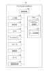
- Fig. 3 is a block diagram showing an example of the circuit configuration of the telepresence robot 20.
- the telepresence robot 20 includes a control circuit 30, a memory 31, an input unit 32, a presentation unit 33, a camera 34, a microphone 35, a speaker 36, a communication unit 37, a sensor 38, and a drive control unit 39. These are connected so that they can transmit and receive information to each other.
- the presentation unit 33, the camera 34, the microphone 35, and the speaker 36 are provided in the video calling unit 23.
- the drive control unit 39 is provided in the moving mechanism 21.
- the control circuit 30, the memory 31, the communication unit 37, and the sensor 38 may be provided in the moving mechanism 21 or in the video calling unit 23.
- the control circuit 30 is, for example, a CPU.
- the control circuit 30 controls the entire telepresence robot 20. More specifically, the control circuit 30 controls the movement of the telepresence robot 20.
- the control circuit 30 also controls the video call with the operator HM1.
- the control circuit 30 executes a program stored in the program storage unit 41 of the memory 31.
- the memory 31 includes a program storage unit 41 and a data storage unit 42. Note that the memory 31 may also include various types of storage devices as external storage, such as a magnetic disk storage device (HDD) or a solid state drive (SSD).
- HDD magnetic disk storage device
- SSD solid state drive
- the program storage unit 41 may be configured as a non-transient storage medium, for example, a non-volatile memory such as a ROM (Read Only Memory).
- the program storage unit 41 stores the execution program of the telepresence robot 20.
- the program includes a movement control program for the telepresence robot 20, a video processing application, and a video call application with the remote control device 10.
- the data storage unit 42 may be configured as a storage medium, for example, a volatile memory such as a RAM (Random Access Memory).
- the data storage unit 42 stores data necessary for the operation of the telepresence robot 20.
- the input unit 32 includes input devices such as a touch panel or button switches.
- the local speaker HM2 may use these input devices to send and receive information to and from the operator HM1. These input devices may also be used during maintenance of the telepresence robot 20.
- the presentation unit 33 includes a display screen 2000 (e.g., an LCD or EL display) as a display device.
- the presentation unit 33 presents a remote image (image of the operator HM1) based on the control of the control circuit 30.
- the image displayed on the presentation unit 33 is switched based on the positional relationship between the telepresence robot 20 and the local speaker HM2.
- Camera 34 is used to capture local video including local speaker HM2 under the control of control circuit 30.
- the microphone 35 is used to acquire local voice, including the voice of the local speaker HM2, based on the control of the control circuit 30.
- the speaker 36 is used to play remote audio (the voice of the operator HM1) based on the control of the control circuit 30.
- the communication unit 37 is used for wireless communication with the remote control device 10. For example, the communication unit 37 transmits local video and audio, as well as information acquired by the telepresence robot 20, to the remote control device 10. The communication unit 37 also receives remote video and audio, as well as operation signals for the telepresence robot 20, from the remote control device 10.
- the telepresence robot 20 includes a plurality of sensors 38.
- the telepresence robot 20 includes a range sensor (laser sensor) or a depth sensor (infrared sensor) to measure the distance to a person or an obstacle.
- the telepresence robot 20 also includes a gyro sensor or an acceleration sensor to measure the inclination of the support 22, the position and moving speed of the telepresence robot 20, etc.
- Information from these sensors 38 is transmitted to the control circuit 30.
- the control circuit 30 controls the moving mechanism 21 (drive control unit 39) based on the information from the sensors 38.
- the drive control unit 39 controls the drive of the wheel drive motor of the moving mechanism 21 based on the control of the control circuit 30.
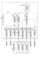
- Fig. 4 is a block diagram showing an example of the functional configuration of the information presentation system 1.
- the remote control device 10 includes an operation acquisition unit 111, a video acquisition unit 112, and a voice acquisition unit 113 as processing functions for presenting information.
- the operation acquisition unit 111, the video acquisition unit 112, and the voice acquisition unit 113 are realized by causing the control circuit 11 to execute a program stored in the program storage unit 121.
- part or all of the operation acquisition unit 111, the video acquisition unit 112, and the voice acquisition unit 113 may be realized using hardware such as an LSI (Large Scale Integration) or an ASIC (Application Specific Integrated Circuit).
- the operation acquisition unit 111 acquires operation instructions for operating the telepresence robot 20 from the operator HM1. More specifically, the operation acquisition unit 111 acquires local information from the local information presentation unit 304 of the telepresence robot 20.
- the local information includes local audio, local video, and person information detected from the local video.
- the local information may also include position information of the telepresence robot 20 and distance information between the telepresence robot 20 and the detected person.
- the operation acquisition unit 111 displays the local information on the display screen 1000.
- the operator HM1 refers to the local information displayed on the display screen 1000 and instructs the operation of the telepresence robot 20.
- the operator HM1 decides whether or not to select that person as the person to be spoken to, that is, the local speaker HM2. Furthermore, when there are multiple people detected from the local video, the operator HM1 can select the local speaker HM2 from among them.
- the operation acquisition unit 111 generates an operation signal that instructs the operator HM1 to approach the local speaker HM2 (the person to be spoken to) selected by the operator HM1, and transmits the operation signal to the local information presentation unit 304.
- the video acquisition unit 112 acquires remote location video, for example of the operator HM1, from the camera 15 of the remote control device 10.
- the video acquisition unit 112 transmits the acquired remote location video to the remote location video acquisition unit 307 of the telepresence robot 20.
- the voice acquisition unit 113 acquires remote voice, including the conversation of the operator HM1, from the microphone 16 of the remote control device 10.
- the voice acquisition unit 113 transmits the acquired remote voice to the remote voice acquisition unit 308 of the telepresence robot 20.
- the telepresence robot 20 includes, as information presentation processing functions, a local voice acquisition unit 301, a local video acquisition unit 302, a person information acquisition unit 303, a local information presentation unit 304, a movement control unit 305, a movement processing unit 306, a remote location video acquisition unit 307, a remote location audio acquisition unit 308, a remote location audio output unit 309, a display screen synthesis unit 310, and a screen display unit 311.
- the local voice acquisition unit 301, the local video acquisition unit 302, the person information acquisition unit 303, the local information presentation unit 304, the movement control unit 305, the movement processing unit 306, the remote location video acquisition unit 307, the remote location audio acquisition unit 308, the remote location audio output unit 309, the display screen synthesis unit 310, and the screen display unit 311 are realized by causing the control circuit 30 to execute a program stored in the program storage unit 41.
- local audio acquisition unit 301 may be realized using hardware such as an LSI or ASIC.
- the local voice acquisition unit 301 acquires local voice from the microphone 35.
- the local voice acquisition unit 301 transmits the acquired local voice to the local information presentation unit 304.
- the local image acquisition unit 302 acquires local image from the camera 34.
- the local image acquisition unit 302 transmits the local image to the person information acquisition unit 303.
- the person information acquisition unit 303 analyzes the on-site video to acquire person information.
- the person information includes information about the person area and the face direction of the person.
- the person area is an area in the on-site video where a person is determined to be included.
- the person information acquisition unit 303 can detect multiple people from the on-site video. For example, YOLO (You Only Look Once) or the like may be used as an algorithm for person (object) detection.
- the person information acquisition unit 303 also detects the face direction of the person in the person area by face direction detection.
- the person information acquisition unit 303 may detect the moving direction of the person.
- the person information acquisition unit 303 can detect the body direction (front direction) of the person by detecting the face direction or the moving direction.
- This person information is used by the operator HM1 to grasp the on-site situation and to process the movement of the telepresence robot 20.
- the person information acquisition unit 303 transmits the on-site video and the person information to the on-site information presentation unit 304 and the movement processing unit 306.
- the local information presentation unit 304 generates local information including local audio, local video, and person information.
- the local information presentation unit 304 presents (transmits) the local information to the operation acquisition unit 111 of the remote control device 10.
- the local information presentation unit 304 also transmits the local information and the operation signal received from the operation acquisition unit 111 to the movement control unit 305.
- the movement control unit 305 controls the movement of the telepresence robot 20. More specifically, the movement control unit 305 recognizes the local speaker HM2 (the person to be spoken to) based on the local information and operation signal received from the local information presentation unit 304. The movement control unit 305 obtains, for example, a result of measuring the distance between the telepresence robot 20 and the local speaker HM2 (hereinafter referred to as the "face-to-face distance") from the sensor 38. The movement control unit 305 transmits information about the local speaker HM2 to the movement processing unit 306. The movement control unit 305 controls the movement of the telepresence robot 20 based on the movement instruction signal received from the movement processing unit 306. More specifically, the movement control unit 305 transmits a drive signal for the wheel drive motor of the movement mechanism 21 to the drive control unit 39.
- the local speaker HM2 the person to be spoken to
- the movement control unit 305 obtains, for example, a result of measuring the distance between the telepresence robot 20 and the local speaker HM
- the movement processing unit 306 selects the method of approaching the local speaker HM2 and the contents of the screen display on the display screen 2000 based on the positional relationship between the telepresence robot 20 and the local speaker HM2. More specifically, the movement processing unit 306 receives information about the local speaker HM2 from the movement control unit 305. The movement processing unit 306 also receives local video and person information. The movement processing unit 306 calculates the positional relationship between the telepresence robot 20 and the local speaker HM2 from this information.
- the information on the positional relationship includes the face-to-face distance between the telepresence robot 20 and the local speaker HM2, and the angle at which the telepresence robot 20 faces from the front of the local speaker HM2.
- the movement processing unit 306 determines the method of movement of the telepresence robot 20 and the contents of the screen display to be presented on the display screen 2000 based on the information on the positional relationship. The details of the method of approaching the local speaker HM2 and the contents of the screen display will be described later.
- the movement processing unit 306 determines the movement direction of the telepresence robot 20 based on the approach method.
- the movement processing unit 306 transmits a movement instruction signal that instructs the movement direction of the telepresence robot 20 to the movement control unit 305.
- the movement processing unit 306 also transmits a display instruction signal that instructs the contents of the screen display to the display screen synthesis unit 310.
- the remote location video acquisition unit 307 acquires remote location video, i.e., video of the operator HM1, from the video acquisition unit 112 of the remote control device 10.
- the remote location video acquisition unit 307 transmits the remote location video to the display screen synthesis unit 310.
- the remote voice acquisition unit 308 acquires remote voice, i.e., the voice of the operator HM1, from the voice acquisition unit 113 of the remote operation device 10.
- the remote voice acquisition unit 308 transmits the remote voice to the remote voice output unit 309 and the display screen synthesis unit 310.
- the remote location audio output unit 309 outputs the remote location audio to the speaker 36 of the telepresence robot 20.
- the display screen synthesis unit 310 receives remote video, i.e., an image of the operator HM1, from the remote video acquisition unit 307.
- the display screen synthesis unit 310 receives remote audio, i.e., the audio of the operator HM1, from the remote audio acquisition unit 308.
- the display screen synthesis unit 310 also receives a display instruction signal from the movement processing unit 306.
- the display screen synthesis unit 310 reads out screen display data 421 from the data storage unit 42 based on the display instruction signal.
- the display screen synthesis unit 310 synthesizes an image to be displayed on the display screen 2000 based on the video and audio of the operator HM1, the display instruction signal, and the screen display data 421.
- the screen display unit 311 displays the image acquired from the display screen synthesis unit 310 as a remote location image on the display screen 2000 of the telepresence robot 20.
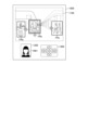
- Fig. 5 is a diagram showing a specific example of screen displays on the display screen 1000 of the remote control device 10.
- a local image display window 1100, a remote image display window 1200, and a controller display window 1300 are displayed on the display screen 1000 of the presentation unit 14.
- Local image display window 1100 displays local image and person information.
- an image of a shopping mall is shown as the local image.
- the person area is shown by frame FR.
- three frames FRa, FRb, and FRc are shown.
- one frame FR may contain multiple people.
- frame FRa contains one woman.
- Frame FRb contains three parents and their children.
- Frame FRc contains a male-female duo.
- the direction of the face (movement direction) of the detected person is indicated by an arrow.
- frame FRb which is indicated by a double frame, is shown in a selected state.
- the remote location video display window 1200 displays the video of operator HM1.
- the controller display window 1300 is used to select the frame FR (local speaker HM2).
- the remote control device 10 transmits an operation signal to the telepresence robot 20 to instruct it to approach the selected local speaker HM2 (the person to be spoken to).
- Fig. 6 is a diagram showing a specific example of a screen display on a display screen 2000 of the telepresence robot 20.
- the display screen 2000 of the presentation unit 33 displays one of a live-action image of the face of the operator HM1 (remote image), an image of the avatar of the operator HM1, and an image of the voice waveform of the operator HM1 (voice waveform of the remote voice).
- a live-action image of the face of the operator HM1 remote image
- an image of the avatar of the operator HM1 image of the voice waveform of the remote voice
- voice waveform of the remote voice For example, an avatar that displays facial elements such as the eyes, nose, and mouth is applied.
- the voice waveform does not need to be displayed as a circular waveform as shown in FIG. 6, so long as it presents the state of the speech voice of the operator HM1.
- the display screen synthesis unit 310 synthesizes one of the images based on a display instruction signal received from the movement processing unit 306.
- the display screen synthesis unit 310 synthesizes an avatar based on the live-action image of the operator HM1 and the screen display data 421.
- the display screen synthesis unit 310 then changes the facial expression of the avatar based on the voice of the operator HM1.
- the anthropomorphism of the images decreases in the order of live-action images, avatars, and audio waveforms.
- the information presentation system 1 can control the acceptance of the local speaker HM2 by displaying images with adjusted anthropomorphism on the display screen 2000 based on the positional relationship between the telepresence robot 20 and the local speaker HM2.
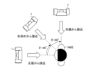
- Fig. 7 is a diagram showing a specific example of a direction in which the telepresence robot 20 approaches the local speaker HM2.
- the telepresence robot 20 can control the direction of approach when approaching the local speaker HM2, i.e., the approach angle.
- the approach angle ⁇ is set to 0° when the telepresence robot 20 approaches the local speaker from the front.
- the approach angle ⁇ is set to 45° when the telepresence robot 20 approaches the local speaker from diagonally to the right.
- the approach angle ⁇ is set to 90° when the telepresence robot 20 approaches the local speaker from the right side.
- the information presentation system 1 can control the sense of acceptance of the local speaker HM2 by adjusting the approach angle ⁇ based on the positional relationship between the telepresence robot 20 and the local speaker HM2.
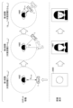
- Fig. 8 is a diagram showing a specific example of the moving direction of the telepresence robot 20 and the screen display of the display screen 2000 when the telepresence robot 20 approaches the local speaker HM2.
- the direction of movement of the telepresence robot 20 and the contents of the screen display of the display screen 2000 are divided into, for example, three stages depending on the facing distance D between the telepresence robot 20 and the local speaker HM2.
- the first stage is a stage where the face-to-face distance D between the telepresence robot 20 and the local speaker HM2 is longer (farther) than a preset first distance d th_app (D>d th_app ).
- the telepresence robot 20 approaches the local speaker HM2 from a relatively long distance.
- a voice waveform with low anthropomorphism is displayed on the display screen 2000 so that the local speaker HM2 is not aware of the conversation. When the voice waveform is displayed, the local speaker HM2 is more receptive than when a live-action video or an avatar is displayed.
- the telepresence robot 20 adjusts the approach angle ⁇ .
- the approach angle ⁇ is preferably 30° ⁇ 60° (diagonal right) or ⁇ 30° ⁇ 60° (diagonal left).
- the telepresence robot 20 is positioned diagonally right or diagonally left with respect to the local speaker HM2, thereby reducing the psychological resistance of the local speaker HM2 to the telepresence robot 20.
- the telepresence robot 20 moves such that the face-to-face distance D is not shorter than the first distance d th_app .
- the telepresence robot 20 moves on an arc with a radius d th_app centered on the local speaker HM2.
- a real-life image of the operator HM1 is displayed on the display screen 2000.
- the third stage is a case where the telepresence robot 20 approaches the local speaker HM2 from the position (first distance d th_app and approach angle ⁇ ) to the second distance d th_fin (d th_app >D ⁇ d th_fin ).
- the second distance d th_fin is shorter than the first distance d th_app .
- the telepresence robot 20 stops when it approaches the second distance d th_fin .
- the telepresence robot 20 approaches the local speaker HM2 from an oblique position, so that the psychological resistance of the local speaker HM2 is reduced.
- an avatar with intermediate anthropomorphism is displayed on the display screen 2000.
- the telepresence robot 20 talks to the local speaker HM2 while the avatar is displayed on the display screen 2000. Displaying an avatar will be more acceptable to local speakers HM2 than displaying live video or audio waveforms.
- the moving speed of the telepresence robot 20 in each stage may be different.
- the moving speed in the third stage may be slower than the first and second stages.
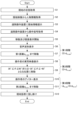
- Fig. 9 is a flowchart showing the overall flow of the information presentation method.
- the telepresence robot 20 acquires the local conditions (S1). More specifically, the local audio acquisition unit 301 acquires local audio. Also, the local video acquisition unit 302 acquires local video.
- the person information acquisition unit 303 acquires person information (information on person area, facial direction, etc.) from the local video (S2).
- the local information presentation unit 304 presents local information (local audio, local video, and person information) to the operation acquisition unit 111 of the remote control device 10 (S3).
- the local information presentation unit 304 acquires an operation signal from the remote control device 10 (S4). More specifically, local information is displayed on the display screen 1000 of the remote control device 10.
- the operator HM1 refers to the display screen 1000 and selects a local speaker HM2.
- the operation acquisition unit 111 transmits an operation signal for the telepresence robot 20 to the local information presentation unit 304 based on the selection result of the operator HM1.
- the telepresence robot 20 starts moving the telepresence robot 20 and displaying the display screen 2000 based on the operation signal (S5). More specifically, the movement processing unit 306 checks the positional relationship between the telepresence robot 20 and the local speaker HM2. If the facing distance D is longer than the first distance d th_app , the movement processing unit 306 selects the first stage of the approach method. The movement processing unit 306 transmits a movement instruction signal to the movement control unit 305 and transmits a display instruction signal to the display screen synthesis unit 310.
- the display screen synthesis unit 310 When the display screen synthesis unit 310 receives a display instruction signal for the first stage of screen display from the movement processing unit 306, it synthesizes the audio waveform.
- the screen display unit 311 displays the audio waveform on the display screen 2000 (S6).
- the movement control unit 305 When the movement control unit 305 receives the first stage movement instruction signal from the movement processing unit 306, it moves the telepresence robot 20 to the first distance d th_app (S7). That is, in the first stage, the telepresence robot 20 approaches the local speaker HM2 to the first distance d th_app while displaying the voice waveform on the display screen 2000.
- the movement processing unit 306 moves to the second stage of the approach method.
- the display screen synthesis unit 310 receives a display instruction signal for the second stage of screen display from the movement processing unit 306, it selects the live-action video of the operator HM1.
- the screen display unit 311 displays the live-action video of the operator HM1 on the display screen 2000 (S8).
- the movement control unit 305 When the movement control unit 305 receives a second-stage movement instruction signal from the movement processing unit 306, it moves the telepresence robot 20 to a position where the approach angle ⁇ is 30° ⁇ 60° (right diagonal) or -30° ⁇ -60° (left diagonal) (S9). That is, in the second stage, the telepresence robot 20 moves to a preset approach angle ⁇ while displaying a live-action image of the operator HM1 on the display screen 2000.
- the movement processing unit 306 moves to the third stage of the approach method.
- the display screen synthesis unit 310 receives a display instruction signal for the third stage screen display from the movement processing unit 306, it synthesizes an avatar of the operator HM1 based on the live video and audio of the operator HM1.
- the screen display unit 311 displays the avatar of the operator HM1 on the display screen 2000 (S10).
- the movement control unit 305 When the movement control unit 305 receives a third-stage movement instruction signal from the movement processing unit 306, the movement control unit 305 moves the telepresence robot 20 to a second distance d th_fin from the position to which the telepresence robot 20 was moved in the second stage (S11). That is, in the third stage, the telepresence robot 20 approaches the local speaker HM2 to the second distance d th_fin while displaying an avatar on the display screen 2000.
- the operator HM1 speaks to the local speaker HM2 via the telepresence robot 20 (S12). Note that the operator HM1 may start speaking to the local speaker HM2 from the first or second stage.
- the information presentation system 1 can switch the moving direction of the telepresence robot 20 and the contents of the screen display of the display screen 2000 according to the distance between the telepresence robot 20 and the local speaker HM2 when the telepresence robot 20 approaches the local speaker HM2.
- the telepresence robot 20 can approach the local speaker HM2 up to a first distance d th_app while displaying a voice waveform on the display screen 2000.
- the telepresence robot 20 can move to a position where 30° ⁇ 60° (right diagonal) or ⁇ 30° ⁇ 60° (left diagonal) while displaying a live-action image of the operator HM1 on the display screen 2000.
- the telepresence robot 20 can approach the local speaker HM2 up to a second distance d th_fin while displaying an avatar on the display screen 2000.
- the telepresence robot 20 can then speak to the local speaker HM2 at a position where the second distance d th_fin is satisfied and 0° ⁇ 60° (right diagonal) or -30° ⁇ -60° (left diagonal).
- a movement direction and screen display contents that pose relatively little psychological resistance to the local speaker HM2 can be selected. This can improve the receptiveness of the local speaker HM2 who is spoken to by the telepresence robot 20 to the telepresence robot 20.
- the present invention is not limited to the above-described embodiment, and various modifications can be made in the implementation stage without departing from the gist of the invention. Furthermore, the embodiments may be implemented in appropriate combinations as far as possible, in which case the combined effects can be obtained. Furthermore, the above-described embodiment includes inventions at various stages, and various inventions can be extracted by appropriate combinations of the multiple components disclosed.
- PROGRAM MEMORY UNIT 42 DATA MEMORY UNIT 111... OPERATION ACQUISITION UNIT 112... VIDEO ACQUISITION UNIT 113... AUDIO ACQUISITION UNIT 121... PROGRAM MEMORY UNIT 122... DATA MEMORY UNIT 301... ON-SITE AUDIO ACQUISITION UNIT 302... ON-SITE VIDEO ACQUISITION UNIT 303... PERSONAL INFORMATION ACQUISITION UNIT 304... ON-SITE INFORMATION PRESENTATION UNIT 305...
- MOVING CONTROL UNIT 306 Movement processing unit 307: Remote location video acquisition unit 308: Remote location audio acquisition unit 309: Remote location audio output unit 310: Display screen synthesis unit 311: Screen display unit 421: Screen display data 1000: Display screen 1100: Local location video display window 1200: Remote location video display window 1300: Controller display window 2000: Display screen HM1: Operator HM2: Local speaker
Landscapes
- Engineering & Computer Science (AREA)
- General Engineering & Computer Science (AREA)
- Theoretical Computer Science (AREA)
- Human Computer Interaction (AREA)
- Physics & Mathematics (AREA)
- General Physics & Mathematics (AREA)
- Manipulator (AREA)
- User Interface Of Digital Computer (AREA)
Abstract
実施形態によれば、情報提示方法は、表示画面に遠隔操作装置が取得した音声の音声波形を表示すること(S6)と、表示画面に音声波形が表示された状態で、ロボットを第1距離まで話し掛け対象者に近づけること(S7)と、表示画面に遠隔操作装置の操作者の実写映像を表示すること(S8)と、表示画面に実写映像が表示された状態で、ロボットを話し掛け対象者に対する角度が第1角度となる位置まで移動させること(S9)と、表示画面に操作者のアバターを表示すること(S10)と、表示画面にアバターが表示された状態で、ロボットを位置から第1距離よりも短い第2距離まで話し掛け対象者に近づけること(S11)とを含む。
Description
本発明の一態様は、遠隔コミュニケーションにおける情報提示方法、情報提示システム、及びプログラムに関する。
近年、近接・対面で行われてきた人間の様々な活動が急速に遠隔化している。例えば、オフィスでは、ハイブリッドワークが一つの勤務体系として確立してきている。ハイブリッドワークは、従来の出社型のオフィスワークと、在宅またはシェアオフィスによるリモートワークとを組み合わせたワークスタイルである。また、商業空間の店舗あるいは施設においてもコミュニケーションの遠隔化が進んできている。
遠隔コミュニケーションツールの1つとして、テレプレゼンスロボットが注目されている。テレプレゼンスロボットは、テレビ会議の機能と遠隔操作技術とが組み合わされたロボットである。テレプレゼンスロボットには、移動機能を有するものがある。テレプレゼンスロボットのような物理的なデバイスを利用することにより、ロボットと対面している通話者が、遠隔地にてテレプレゼンスロボットを操作している通話者の存在を感じやすくなる。
例えば、非特許文献1には、オフィス空間におけるテレプレゼンスロボットの使用例が示されている。また、非特許文献2には、商業空間(店舗)におけるテレプレゼンスロボットの使用例が示されている。
Maral Muratbekova-Touron、Emmanuelle Leon、「"Is there anybody out there?" Using a telepresence robot to engage in face time at the office」、Information Technology & People、2023年、Vol. 36、No. 1、p. 48-65
和田一義、「リテール空間におけるロボット技術」、日本機械学会誌、2021年5月、Vol. 124、No. 1230、p. 34-35
日戸浩之、谷山大介、稲垣仁美、「ロボット・AI技術導入をめぐる生活者の受容性と課題、日米独3カ国調査からの示唆」、知的資産創造、2016年5月号、p. 108-125
遠隔コミュニケーションにおいて、初対面の人とテレプレゼンスロボットを介して会話をする場合、お互いによく知っている人と会話する場合に比べて、心理的抵抗感が強くなる。例えば、お互いを知っているオフィス空間に比べて、初対面のスタッフと訪問客とが対話する商業空間では、テレプレゼンスロボットからの話しかけは、心理的な抵抗感が生じやすく、コミュニケーションが受容されにくい。例えば、非特許文献3には、ロボットに対する受容性に関する調査結果が示されている。
本願発明はこうした点に鑑みてなされたものである。本願発明は、ロボットを用いた遠隔コミュニケーションにおける情報提示方法において、ロボットとの会話に対する心理的抵抗感を低減することを目的とする。
一態様の情報提示方法は、移動機構及び表示画面を含みビデオ通話機能を有するロボットと、ロボットの遠隔操作装置とを備える情報提示システムを用いた情報提示方法であって、表示画面に遠隔操作装置が取得した音声の音声波形を表示することと、表示画面に音声波形が表示された状態で、ロボットを第1距離まで話し掛け対象者に近づけることと、表示画面に遠隔操作装置の操作者の実写映像を表示することと、表示画面に実写映像が表示された状態で、ロボットを話し掛け対象者に対する角度が第1角度となる位置まで移動させることと、表示画面に操作者のアバターを表示することと、表示画面にアバターが表示された状態で、ロボットを位置から第1距離よりも短い第2距離まで話し掛け対象者に近づけることとを含む。
実施形態によれば、情報提示方法は、画面表示機能と移動機能とを有するテレプレゼンスロボットを用いた遠隔コミュニケーションにおいて、テレプレゼンスロボットが人に接近して会話を試みる際に、表示画面と、人への接近方法を制御できる。これにより、テレプレゼンスロボットに話し掛けられる人が、テレプレゼンスロボットを受け入れる受容感を向上できる。
以下、図面を参照して実施形態について説明する。なお、以下の説明において、同一の機能及び構成を有する構成要素については、共通する参照符号を付す。
1.情報提示システムの全体構成
まず、図1を参照して、情報提示システム1の全体構成の一例について説明する。図1は、情報提示システム1の全体構成の一例を示すブロック図である。
まず、図1を参照して、情報提示システム1の全体構成の一例について説明する。図1は、情報提示システム1の全体構成の一例を示すブロック図である。
図1に示すように、例えば、情報提示システム1は、遠隔操作装置10と、遠隔操作装置10と通信可能なテレプレゼンスロボット20(以下、単に「ロボット」とも表記する)とを含む。以下の説明において、遠隔操作装置10の操作場所を「遠隔地」と表記する。また、テレプレゼンスロボット20が稼働している場所を「現地」と表記する。
遠隔操作装置10は、例えば、パーソナルコンピュータである。なお、遠隔操作装置10は、スマートフォン等のタブレット端末であってもよいし、他のコンピュータ装置であってもよい。遠隔操作装置10は、テレプレゼンスロボット20を遠隔操作する機能を有する。また、遠隔操作装置10は、テレプレゼンスロボット20とビデオ通話(ビデオチャット)を実行する機能を有する。例えば、遠隔操作装置10の表示画面1000には、現地の映像が表示される。遠隔操作装置10を操作する人(以下、「操作者HM1」と表記する)は、遠隔操作装置10を介して、テレプレゼンスロボット20を操作し得る。例えば、操作者HM1は、テレプレゼンスロボット20を操作して、現地で話し掛ける人を探したり、話し掛け対象者にテレプレゼンスロボット20を接近させたりする。または、操作者HM1は、遠隔操作装置10とテレプレゼンスロボット20との間のビデオ通話機能を利用して、テレプレゼンスロボット20と対面している話し掛け対象者(以下、「現地話者HM2」と表記する)に話し掛ける。
テレプレゼンスロボット20は、移動機構21、支柱22、及びビデオ通話ユニット23を含む。なお、テレプレゼンスロボット20は、移動可能なヒューマノイドロボットであってもよい。
移動機構21は、遠隔操作装置10による操作に基づいて、テレプレゼンスロボット20を移動させる。移動機構21は、台座、車輪、車輪駆動(回転)用モータ等を含む。図示せぬ車輪駆動用モータは、台座内に設置されている。図1の例では、円柱形状の台座の側面(左右)に2つの車輪が設けられている。2つの車輪には、それぞれ別の車輪駆動用モータが取り付けられている。2つの車輪は、互いに独立して制御される。左右の車輪の回転を制御することにより、テレプレゼンスロボット20は、走行及び旋回し得る。なお、台座及び車輪の構成及び配置はこれに限定されない。例えば、台座は直方体であってもよい。また、車輪は、3つ以上設けられていてもよい。
支柱22は、移動機構21の上に設けられる。支柱22の上には、ビデオ通話ユニット23が設けられている。支柱22は、伸縮機構が設けられてもよいし、及びビデオ通話ユニット23(表示画面2000)を回転させる回転機構が設けられていてもよい。例えば、テレプレゼンスロボット20は、現地話者HM2の身長に合わせて、支柱22の長さを調整し得る。また、テレプレゼンスロボット20は、移動機構21の進行方向と、現地話者HM2との位置関係に応じて、ビデオ通話ユニット23(表示画面2000)の向きを変更し得る。
ビデオ通話ユニット23は、ビデオ通話に用いられる。ビデオ通話ユニット23は、表示画面2000を含む。表示画面2000には、遠隔地の映像(操作者HM1の映像)が表示される。
1.1 遠隔操作装置の回路構成
次に、図2を参照して、遠隔操作装置10の回路構成の一例について説明する。図2は、遠隔操作装置10の回路構成の一例を示すブロック図である。
次に、図2を参照して、遠隔操作装置10の回路構成の一例について説明する。図2は、遠隔操作装置10の回路構成の一例を示すブロック図である。
図2に示すように、遠隔操作装置10は、制御回路11、メモリ12、入力部13、提示部14、カメラ15、マイクロフォン16、スピーカ17、及び通信部18を含む。これらは、互いに送受信可能に接続される。
制御回路11は、例えば、CPU(Central Processing Unit)である。制御回路11は、遠隔操作装置10の全体を制御する。制御回路11は、メモリ12のプログラム記憶部121に記憶されたプログラムを実行する。
メモリ12は、プログラム記憶部121及びデータ記憶部122を含む。なお、メモリ12は、外部ストレージとして、磁気ディスク記憶装置(HDD:Hard Disk Drive)またはソリッドステートドライブ(SSD:Solid State Drive)等の各種記憶装置を含んでいてもよい。
プログラム記憶部121は、非一時的な記憶媒体として、例えば、ROM(Read Only Memory)等の不揮発性メモリにより構成され得る。プログラム記憶部121は、情報提示システム1の実行に用いられるプログラムを記憶する。例えば、プログラムには、テレプレゼンスロボット20の操作プログラム及びテレプレゼンスロボット20とのビデオ通話アプリケーションが含まれる。
データ記憶部122は、記憶媒体として、例えば、RAM(Random Access Memory)等の揮発性メモリにより構成され得る。データ記憶部122には、情報提示システム1の実行に必要なデータが記憶される。
入力部13は、キーボード、マウス、タッチパネル、またはボタンスイッチ等の入力装置を含む。操作者HM1は、入力装置を用いて、テレプレゼンスロボット20を操作し得る。
提示部14は、表示装置として、表示画面1000(例えば、LCD(Liquid Crystal Display)またはEL(Electroluminescence)ディスプレイ等)を含む。例えば、提示部14は、制御回路11の制御に基づいて、現地で撮影された映像(以下、「現地映像」と表記する)を表示画面1000に表示する。
カメラ15は、制御回路11の制御に基づいて、遠隔地の撮影、すなわち、操作者HM1の撮影に用いられる。以下、カメラ15により遠隔地で撮影された映像を「遠隔地映像」と表記する。
マイクロフォン16は、制御回路11の制御に基づいて、遠隔地の音声(以下、「遠隔地音声」と表記する)、すなわち、操作者HM1の音声取得に用いられる。
スピーカ17は、制御回路11の制御に基づいて、現地にて取得された音声(以下、「現地音声」と表記する)の再生に用いられる。
通信部18は、テレプレゼンスロボット20との無線通信に用いられる。例えば、通信部18は、テレプレゼンスロボット20に、遠隔地映像及び遠隔地音声(操作者HM1の映像及び音声)、並びにテレプレゼンスロボット20の操作信号を送信する。また、通信部18は、テレプレゼンスロボット20から、現地映像及び現地音声、並びにテレプレゼンスロボット20が取得した情報を受信する。
なお、マイクロフォン16及びスピーカ17は、遠隔操作装置10に内蔵されていてもよいし、遠隔操作装置10に接続されたマイクロフォン付きイヤホンまたはヘッドフォンであってもよい。
1.2 テレプレゼンスロボット20の回路構成
次に、図3を参照して、テレプレゼンスロボット20の回路構成について説明する。図3は、テレプレゼンスロボット20の回路構成の一例を示すブロック図である。
次に、図3を参照して、テレプレゼンスロボット20の回路構成について説明する。図3は、テレプレゼンスロボット20の回路構成の一例を示すブロック図である。
図3に示すように、テレプレゼンスロボット20は、制御回路30、メモリ31、入力部32、提示部33、カメラ34、マイクロフォン35、スピーカ36、通信部37、センサ38、及び駆動制御部39を含む。これらは、互いに送受信可能に接続される。例えば、提示部33、カメラ34、マイクロフォン35、及びスピーカ36は、ビデオ通話ユニット23内に設けられる。駆動制御部39は、移動機構21内に設けられる。制御回路30、メモリ31、通信部37、及びセンサ38は、移動機構21内に設けれてもよいし、ビデオ通話ユニット23内に設けられてもよい。
制御回路30は、例えば、CPUである。制御回路30は、テレプレゼンスロボット20の全体を制御する。より具体的には、制御回路30は、テレプレゼンスロボット20の移動を制御する。また、制御回路30は、操作者HM1とのビデオ通話を制御する。制御回路30は、メモリ31のプログラム記憶部41に記憶されたプログラムを実行する。
メモリ31は、プログラム記憶部41及びデータ記憶部42を含む。なお、メモリ31は、外部ストレージとして、磁気ディスク記憶装置(HDD)またはソリッドステートドライブ(SSD)等の各種記憶装置を含んでいてもよい。
プログラム記憶部41は、非一時的な記憶媒体として、例えば、ROM(Read Only Memory)等の不揮発性メモリにより構成され得る。プログラム記憶部41は、テレプレゼンスロボット20の実行プログラムを記憶する。例えば、プログラムには、テレプレゼンスロボット20の移動制御プログラム、映像処理用アプリケーション、及び遠隔操作装置10とのビデオ通話アプリケーションが含まれる。
データ記憶部42は、記憶媒体として、例えば、RAM(Random Access Memory)等の揮発性メモリにより構成され得る。データ記憶部42には、テレプレゼンスロボット20の動作に必要なデータが記憶される。
入力部32は、タッチパネルまたはボタンスイッチ等の入力装置を含む。例えば、現地話者HM2は、これら入力装置を用いて、操作者HM1と情報の送受信を行ってもよい。また、テレプレゼンスロボット20のメンテナンスの際に、これらの入力装置が用いられてもよい。
提示部33は、表示装置として、表示画面2000(例えば、LCDまたはELディスプレイ等)を含む。例えば、提示部33は、制御回路30の制御に基づいて、遠隔地映像(操作者HM1の映像)を提示する。なお、提示部33に表示される映像は、テレプレゼンスロボット20と現地話者HM2との位置関係に基づいて、切り替えられる。
カメラ34は、制御回路30の制御に基づいて、現地話者HM2を含む現地映像の撮影に用いられる。
マイクロフォン35は、制御回路30の制御に基づいて、現地話者HM2の音声を含む現地音声の取得に用いられる。
スピーカ36は、制御回路30の制御に基づいて、遠隔地音声(操作者HM1の音声)の再生に用いられる。
通信部37は、遠隔操作装置10との無線通信に用いられる。例えば、通信部37は、遠隔操作装置10に、現地映像及び現地音声、並びにテレプレゼンスロボット20が取得した情報を送信する。また、通信部37は、遠隔操作装置10から、遠隔地映像及び遠隔地音声、並びにテレプレゼンスロボット20の操作信号を受信する。
テレプレゼンスロボット20は、複数のセンサ38を含む。例えば、テレプレゼンスロボット20は、人あるいは障害物との距離を計測するために、測域センサ(レーザーセンサ)または深度センサ(赤外線センサ)等を含む。また、例えば、テレプレゼンスロボット20は、支柱22の傾斜、テレプレゼンスロボット20の位置及び移動速度等を計測するために、ジャイロセンサまたは加速度センサ等を含む。これらのセンサ38の情報は、制御回路30に送信される。例えば、制御回路30は、センサ38の情報に基づいて、移動機構21(駆動制御部39)を制御する。
駆動制御部39は、制御回路30の制御に基づいて、移動機構21の車輪駆動用モータの駆動を制御する。
1.3 情報提示システムの機能構成
次に、図4を参照して、情報提示システム1の機能構成について説明する。図4は、情報提示システム1の機能構成の一例を示すブロック図である。
次に、図4を参照して、情報提示システム1の機能構成について説明する。図4は、情報提示システム1の機能構成の一例を示すブロック図である。
まず、遠隔操作装置10の機能構成について説明する。
図4に示すように、遠隔操作装置10は、情報提示の処理機能として、操作取得部111、映像取得部112、及び音声取得部113を含む。操作取得部111、映像取得部112、及び音声取得部113は、制御回路11にプログラム記憶部121に格納されたプログラムを実行させることにより実現される。なお、操作取得部111、映像取得部112、及び音声取得部113の一部または全部は、LSI(Large Scale Integration)やASIC(Application Specific Integrated Circuit)等のハードウェアを用いて実現されてもよい。
操作取得部111は、操作者HM1からテレプレゼンスロボット20を操作するための操作指示を取得する。より具体的には、操作取得部111は、テレプレゼンスロボット20の現地情報提示部304から現地情報を取得する。現地情報には、現地音声、現地映像、及び現地映像から検出された人物情報が含まれる。なお、現地情報には、テレプレゼンスロボット20の位置情報及びテレプレゼンスロボット20と検出された人物との距離情報が含まれてもよい。操作取得部111は、現地情報を表示画面1000に表示する。操作者HM1は、表示画面1000に表示された現地情報を参照し、テレプレゼンスロボット20の操作を指示する。例えば、操作者HM1は、現地映像から検出された人物が一人である場合、当該人物を話し掛け対象者、すなわち、現地話者HM2として選択するか否かを決定する。また、操作者HM1は、現地映像から検出された人物が複数人いる場合、その中から現地話者HM2を選択し得る。操作取得部111は、操作者HM1が選択した現地話者HM2(話し掛け対象者)への接近を指示する操作信号を生成し、現地情報提示部304に操作信号を送信する。
映像取得部112は、遠隔操作装置10のカメラ15から、例えば操作者HM1が撮影された遠隔地映像を取得する。映像取得部112は、テレプレゼンスロボット20の遠隔地映像取得部307に、取得した遠隔地映像を送信する。
音声取得部113は、遠隔操作装置10のマイクロフォン16から、操作者HM1の会話を含む遠隔地音声を取得する。音声取得部113は、テレプレゼンスロボット20の遠隔地音声取得部308に、取得した遠隔地音声を送信する。
次に、テレプレゼンスロボット20の機能構成について説明する。テレプレゼンスロボット20は、情報提示の処理機能として、現地音声取得部301、現地映像取得部302、人物情報取得部303、現地情報提示部304、移動制御部305、移動処理部306、遠隔地映像取得部307、遠隔地音声取得部308、遠隔地音声出力部309、表示画面合成部310、及び画面表示部311を含む。現地音声取得部301、現地映像取得部302、人物情報取得部303、現地情報提示部304、移動制御部305、移動処理部306、遠隔地映像取得部307、遠隔地音声取得部308、遠隔地音声出力部309、表示画面合成部310、及び画面表示部311は、制御回路30にプログラム記憶部41に格納されたプログラムを実行させることにより実現される。なお、現地音声取得部301、現地映像取得部302、人物情報取得部303、現地情報提示部304、移動制御部305、移動処理部306、遠隔地映像取得部307、遠隔地音声取得部308、遠隔地音声出力部309、表示画面合成部310、及び画面表示部311の一部または全部は、LSIやASIC等のハードウェアを用いて実現されてもよい。
現地音声取得部301は、マイクロフォン35から、現地音声を取得する。現地音声取得部301は、現地情報提示部304に、取得した現地音声を送信する。
現地映像取得部302は、カメラ34から、現地映像を取得する。現地映像取得部302は、人物情報取得部303に、現地映像を送信する。
人物情報取得部303は、現地映像を解析して、人物情報を取得する。人物情報は、人物領域及び人物の顔の向きについての情報を含む。人物領域は、現地映像において、人物が写っていると判定された領域である。人物情報取得部303は、現地映像から複数人の人物を検出し得る。例えば、人物(物体)検出のアルゴリズムとして、YOLO(You Only Look Once)等が用いられてもよい。また、人物情報取得部303は、顔向き検出により、人物領域内の人物の顔の向きを検出する。なお、人物情報取得部303は、人物の移動方向を検出してもよい。人物情報取得部303は、顔向き検出または移動方向の検出により、人物の体の向き(正面方向)を検出し得る。これらの人物情報は、操作者HM1による現場状況の把握及びテレプレゼンスロボット20の移動処理に用いられる。人物情報取得部303は、現地情報提示部304及び移動処理部306に、現地映像及び人物情報を送信する。
現地情報提示部304は、現地音声、現地映像、及び人物情報を含む現地情報を生成する。現地情報提示部304は、遠隔操作装置10の操作取得部111に、現地情報を提示(送信)する。また、現地情報提示部304は、移動制御部305に、現地情報及び操作取得部111から受信した操作信号を送信する。
移動制御部305は、テレプレゼンスロボット20の移動を制御する。より具体的には、移動制御部305は、現地情報提示部304から受信した現地情報及び操作信号により、現地話者HM2(話し掛け対象者)を認識する。移動制御部305は、例えば、センサ38から、テレプレゼンスロボット20と現地話者HM2との間の距離(以下、「対面距離」と表記する)を計測した結果を取得する。移動制御部305は、これらの現地話者HM2に関する情報を移動処理部306に送信する。移動制御部305は、移動処理部306から受信した移動指示信号に基づいて、テレプレゼンスロボット20の移動を制御する。より具体的には、移動制御部305は、駆動制御部39に移動機構21の車輪駆動用モータの駆動信号を送信する。
移動処理部306は、テレプレゼンスロボット20が現地話者HM2に向かって移動する際に、テレプレゼンスロボット20と現地話者HM2との位置関係から、現地話者HM2への接近方法及び表示画面2000における画面表示の内容を選択する。より具体的には、移動処理部306は、移動制御部305から現地話者HM2に関する情報を受信する。また、移動処理部306は、現地映像及び人物情報を受信する。移動処理部306は、これらの情報からテレプレゼンスロボット20と現地話者HM2との位置関係を算出する。位置関係の情報には、テレプレゼンスロボット20と現地話者HM2との対面距離、及び現地話者HM2の正面からテレプレゼンスロボット20を向いた角度が含まれる。移動処理部306は、位置関係の情報から、テレプレゼンスロボット20の移動方法及び表示画面2000に提示する画面表示の内容を決定する。現地話者HM2への接近方法及び画面表示の内容の詳細については、後述する。移動処理部306は、接近方法に基づいて、テレプレゼンスロボット20の移動方向を決定する。移動処理部306は、テレプレゼンスロボット20の移動方向を指示する移動指示信号を移動制御部305に送信する。また、移動処理部306は、画面表示の内容を指示する表示指示信号を表示画面合成部310に送信する。
遠隔地映像取得部307は、遠隔操作装置10の映像取得部112から、遠隔地映像、すなわち、操作者HM1の映像を取得する。遠隔地映像取得部307は、表示画面合成部310に、遠隔地映像を送信する。
遠隔地音声取得部308は、遠隔操作装置10の音声取得部113から、遠隔地音声、すなわち、操作者HM1の音声を取得する。遠隔地音声取得部308は、遠隔地音声出力部309及び表示画面合成部310に、遠隔地音声を送信する。
遠隔地音声出力部309は、テレプレゼンスロボット20のスピーカ36に、遠隔地音声を出力する。
表示画面合成部310は、遠隔地映像取得部307から、遠隔地映像、すなわち、操作者HM1の画像を受信する。表示画面合成部310は、遠隔地音声取得部308から、遠隔地音声、すなわち、操作者HM1の音声を受信する。また、表示画面合成部310は、移動処理部306から、表示指示信号を受信する。表示画面合成部310は、表示指示信号に基づいて、データ記憶部42から画面表示データ421を読み出す。表示画面合成部310は、操作者HM1の映像及び音声、表示指示信号、及び画面表示データ421に基づいて、表示画面2000に表示させる映像を合成する。
画面表示部311は、テレプレゼンスロボット20の表示画面2000に、遠隔地映像として、表示画面合成部310から取得した映像を表示させる。
2.遠隔操作装置における画面表示の具体例
次に、図5を参照して、遠隔操作装置10における画面表示の具体例について説明する。図5は、遠隔操作装置10の表示画面1000における画面表示の具体例を示す図である。
次に、図5を参照して、遠隔操作装置10における画面表示の具体例について説明する。図5は、遠隔操作装置10の表示画面1000における画面表示の具体例を示す図である。
図5に示すように、例えば、提示部14の表示画面1000には、現地映像表示ウィンドウ1100、遠隔地映像表示ウィンドウ1200、及びコントローラ表示ウィンドウ1300が表示される。
現地映像表示ウィンドウ1100には、現地映像及び人物情報が表示される。図5の例では、現地映像としてショッピングモールの映像が示されている。この中で、人物領域は、フレームFRで示されている。図5の例では、3つのフレームFRa、FRb、及びFRcが示されている。なお、1つのフレームFR内に、複数の人物が含まれていてもよい。例えば、フレームFRaには、一人の女性が含まれている。フレームFRbには、子供連れの三人の親子が含まれている。フレームFRcには、男女二人組が含まれている。各フレームFRにおいて、検出された人物の顔の向き(移動方向)が矢印で示されている。図5の例では、二重枠で示されたフレームFRbが選択された状態を示している。
遠隔地映像表示ウィンドウ1200には、操作者HM1の映像が表示されている。
コントローラ表示ウィンドウ1300には、上下左右をそれぞれ示す4つの矢印キーが表示されている。コントローラ表示ウィンドウ1300は、フレームFR(現地話者HM2)の選択に用いられる。
フレームFRの選択方法として、例えば2つの方法がある。1つは、コントローラ表示ウィンドウ1300の矢印キーを操作(クリック)して、フレームFRを選択する方法である。もう1つは、対象のフレームFR内をクリックすることによりフレームFRを選択する方法である。例えば、遠隔操作装置10は、テレプレゼンスロボット20に、選択された現地話者HM2(話し掛け対象者)への接近を指示する操作信号を送信する。
3.テレプレゼンスロボットにおける画面表示の具体例
次に、図6を参照して、テレプレゼンスロボット20における画面表示の具体例について説明する。図6は、テレプレゼンスロボット20の表示画面2000における画面表示の具体例を示す図である。
次に、図6を参照して、テレプレゼンスロボット20における画面表示の具体例について説明する。図6は、テレプレゼンスロボット20の表示画面2000における画面表示の具体例を示す図である。
図6に示すように、例えば、提示部33の表示画面2000には、操作者HM1の顔の実写映像(遠隔地映像)、操作者HM1のアバターの映像、及び操作者HM1の音声波形(遠隔地音声の音声波形)の映像のいずれかが表示される。例えば、アバターには、目、鼻、口といった顔の要素が表示されるものが適用される。なお、音声波形は、操作者HM1の発話音声の状況を提示するものであれば、図6に示したような円形の波形表示で無くてもよい。表示画面合成部310は、移動処理部306から受信した表示指示信号に基づいて、いずれかの映像を合成する。例えば、表示画面合成部310は、操作者HM1の実写映像と画面表示データ421とに基づいてアバターを合成する。そして、表示画面合成部310は、操作者HM1の音声に基づいて、アバターの表情を変化させる。
映像の擬人性は、実写映像、アバター、音声波形の順に低くなる。情報提示システム1は、テレプレゼンスロボット20と現地話者HM2との位置関係に基づいて、表示画面2000に、擬人性を調整した映像を表示することにより、現地話者HM2の受容感を制御できる。
4.テレプレゼンスロボットが現地話者に接近する方向の具体例
次に、図7を参照して、テレプレゼンスロボット20が現地話者HM2に接近する方向の具体例について説明する。図7は、テレプレゼンスロボット20が現地話者HM2に接近する方向の具体例を示す図である。
次に、図7を参照して、テレプレゼンスロボット20が現地話者HM2に接近する方向の具体例について説明する。図7は、テレプレゼンスロボット20が現地話者HM2に接近する方向の具体例を示す図である。
図7に示すように、テレプレゼンスロボット20は、現地話者HM2に接近する際に接近する方向、すなわち、接近角度を制御できる。例えば、テレプレゼンスロボット20が現地話者の正面から接近する場合の接近角度θを0°とする。テレプレゼンスロボット20が現地話者の右斜めから接近する場合の接近角度θを45°とする。また、テレプレゼンスロボット20が現地話者の右横から接近する場合の接近角度θを90°とする。情報提示システム1は、テレプレゼンスロボット20と現地話者HM2との位置関係に基づいて、接近角度θを調整することにより、現地話者HM2の受容感を制御できる。
5.現地話者への接近方法
次に、図8を参照して、テレプレゼンスロボット20が現地話者HM2に接近する方法の一例について説明する。図8は、テレプレゼンスロボット20が現地話者HM2に接近する際のテレプレゼンスロボット20の移動方向及び表示画面2000の画面表示の具体例を示す図である。
次に、図8を参照して、テレプレゼンスロボット20が現地話者HM2に接近する方法の一例について説明する。図8は、テレプレゼンスロボット20が現地話者HM2に接近する際のテレプレゼンスロボット20の移動方向及び表示画面2000の画面表示の具体例を示す図である。
図8に示すように、テレプレゼンスロボット20が現地話者HM2に接近する場合、テレプレゼンスロボット20の移動方向及び表示画面2000の画面表示の内容は、テレプレゼンスロボット20と現地話者HM2との対面距離Dに応じて、例えば、3段階に分けられる。
まず、第1段階は、テレプレゼンスロボット20と現地話者HM2との対面距離Dが予め設定された第1距離dth_appよりも長い(遠い)段階(D>dth_app)である。テレプレゼンスロボット20は、現地話者HM2に、比較的遠方から接近する。第1段階では、接近角度θは限定されない。なお、例えば、現地話者HM2の正面(接近角度θ=0°)からテレプレゼンスロボット20が接近してくると、現地話者HM2は、テレプレゼンスロボット20の存在に気づきやすい。第1段階では、現地話者HM2に話し掛けを意識させないようにするため、表示画面2000に擬人性の低い音声波形が表示される。音声波形を表示すると、実写映像またはアバターを表示する場合よりも現地話者HM2の受容性は大きくなる。
第2段階は、テレプレゼンスロボット20が第1距離dth_appまで現地話者HM2に近づいた段階(D=dth_app)である。第2段階で、テレプレゼンスロボット20は、接近角度θを調整する。例えば、接近角度θとしては、30°≦θ≦60°(右斜め)または-30°≦θ≦-60°(左斜め)が好適である。例えば、テレプレゼンスロボット20が現地話者HM2に対して右斜めまたは左斜めに位置することにより、現地話者HM2のテレプレゼンスロボット20に対する心理的抵抗感が低減される。このとき、テレプレゼンスロボット20は、対面距離Dが第1距離dth_appよりも短くならない移動する。例えば、テレプレゼンスロボット20は、現地話者HM2を中心した半径dth_appの円弧上を移動する。第2段階では、現地話者HM2に心理的抵抗感を感じさせないようにするため、表示画面2000に操作者HM1の実写映像を表示する。
第3段階は、テレプレゼンスロボット20が現地話者HM2に第2段階で移動した位置(第1距離dth_app且つ接近角度θ)から第2距離dth_finまで接近する場合(dth_app>D≧dth_fin)である。第2距離dth_finは、第1距離dth_appよりも短い距離である。テレプレゼンスロボット20は、第2距離dth_finまで接近すると静止する。現地話者HM2は、テレプレゼンスロボット20が斜めの位置から接近してくるため、心理的抵抗感が低減される。第3段階では、テレプレゼンスロボット20に対する心理的抵抗感を低減するために、表示画面2000に、擬人性が中間となるアバターが表示される。テレプレゼンスロボット20は、表示画面2000にアバターが表示されている状態で、現地話者HM2に話し掛ける。アバターを表示すると、実写映像または音声波形を表示する場合よりも、現地話者HM2の受容性は大きくなる。
なお、各段階のテレプレゼンスロボット20の移動速度は、異なっていてもよい。例えば、第3段階の移動速度は、第1段階及び第2段階よりも遅くてもよい。
6.情報提示方法の全体の流れ
次に、図9を参照して、情報提示方法の流れの一例について説明する。図9は、情報提示方法の全体の流れを示すフローチャートである。
次に、図9を参照して、情報提示方法の流れの一例について説明する。図9は、情報提示方法の全体の流れを示すフローチャートである。
図9に示すように、まず、テレプレゼンスロボット20は、現地の状態を取得する(S1)。より具体的には、現地音声取得部301は、現地音声を取得する。また、現地映像取得部302は、現地映像を取得する。
人物情報取得部303は、現地映像から人物情報(人物領域及び顔向き等の情報)を取得する(S2)。
現地情報提示部304は、遠隔操作装置10の操作取得部111に、現地情報(現地音声、現地映像、及び人物情報)を提示する(S3)。
現地情報提示部304は、遠隔操作装置10から操作信号を取得する(S4)。より具体的には、遠隔操作装置10の表示画面1000には、現地情報が表示される。操作者HM1は、表示画面1000を参照して、現地話者HM2を選択する。操作取得部111は、操作者HM1の選択結果に基づいて、現地情報提示部304に、テレプレゼンスロボット20の操作信号を送信する。
テレプレゼンスロボット20は、操作信号に基づいて、テレプレゼンスロボット20の移動及び表示画面2000の画面表示を開始する(S5)。より具体的には、移動処理部306は、テレプレゼンスロボット20と現地話者HM2との位置関係を確認する。対面距離Dが第1距離dth_appより長い場合、移動処理部306は、接近方法の第1段階を選択する。移動処理部306は、移動制御部305に移動指示信号を送信し、表示画面合成部310に表示指示信号を送信する。
表示画面合成部310は、移動処理部306から第1段階の画面表示の表示指示信号を受信すると、音声波形を合成する。画面表示部311は、表示画面2000に音声波形を表示する(S6)。
移動制御部305は、移動処理部306から第1段階の移動指示信号を受信すると、テレプレゼンスロボット20を第1距離dth_appまで移動させる(S7)。すなわち、第1段階として、テレプレゼンスロボット20は、表示画面2000に音声波形を表示させながら、第1距離dth_appまで現地話者HM2に接近する。
移動処理部306は、接近方法の第1段階が終了すると、接近方法の第2段階に移行する。表示画面合成部310は、移動処理部306から第2段階の画面表示の表示指示信号を受信すると、操作者HM1の実写映像を選択する。画面表示部311は、表示画面2000に操作者HM1の実写映像を表示する(S8)。
移動制御部305は、移動処理部306から第2段階の移動指示信号を受信すると、接近角度θが、30°≦θ≦60°(右斜め)または-30°≦θ≦-60°(左斜め)となる位置に、テレプレゼンスロボット20を移動させる(S9)。すなわち、第2段階として、テレプレゼンスロボット20は、表示画面2000に操作者HM1の実写映像を表示させながら、予め設定された接近角度θまで移動する。
移動処理部306は、接近方法の第2段階が終了すると、接近方法の第3段階に移行する。表示画面合成部310は、移動処理部306から第3段階の画面表示の表示指示信号を受信すると、操作者HM1の実写映像及び音声に基づいて、操作者HM1のアバターを合成する。画面表示部311は、表示画面2000に操作者HM1のアバターを表示する(S10)。
移動制御部305は、移動処理部306から第3段階の移動指示信号を受信すると、テレプレゼンスロボット20を第2段階で移動した位置から第2距離dth_finまで移動させる(S11)。すなわち、第3段階として、テレプレゼンスロボット20は、表示画面2000にアバターを表示させながら、第2距離dth_finまで現地話者HM2に接近する。
操作者HM1は、テレプレゼンスロボット20を介して、現地話者HM2に話し掛ける(S12)。なお、操作者HM1は、第1段階または第2段階から現地話者HM2に話し掛けを開始してもよい。
7.本実施形態に係る効果
本実施形態に係る構成であれば、情報提示システム1は、テレプレゼンスロボット20が現地話者HM2に接近する際に、テレプレゼンスロボット20と現地話者HM2との距離に応じて、テレプレゼンスロボット20の移動方向と表示画面2000の画面表示の内容を切り換えることができる。例えば、第1段階では、テレプレゼンスロボット20は、表示画面2000に音声波形を表示させながら、第1距離dth_appまで現地話者HM2に接近できる。第2段階では、テレプレゼンスロボット20は、表示画面2000に操作者HM1の実写映像を表示させながら、30°≦θ≦60°(右斜め)または-30°≦θ≦-60°(左斜め)となる位置に移動できる。第3段階では、テレプレゼンスロボット20は、表示画面2000にアバターを表示させながら、第2距離dth_finまで現地話者HM2に接近できる。そして、テレプレゼンスロボット20は、第2距離dth_fin且つ0°≦θ≦60°(右斜め)または-30°≦θ≦-60°(左斜め)となる位置で現地話者HM2に話し掛けることができる。テレプレゼンスロボット20と現地話者HM2との位置関係に応じて、現地話者HM2の心理的抵抗感の比較的少ない移動方向及び画面表示の内容を選択できる。よって、テレプレゼンスロボット20に話し掛けられる現地話者HM2がテレプレゼンスロボット20を受け入れる受容感を向上できる。
本実施形態に係る構成であれば、情報提示システム1は、テレプレゼンスロボット20が現地話者HM2に接近する際に、テレプレゼンスロボット20と現地話者HM2との距離に応じて、テレプレゼンスロボット20の移動方向と表示画面2000の画面表示の内容を切り換えることができる。例えば、第1段階では、テレプレゼンスロボット20は、表示画面2000に音声波形を表示させながら、第1距離dth_appまで現地話者HM2に接近できる。第2段階では、テレプレゼンスロボット20は、表示画面2000に操作者HM1の実写映像を表示させながら、30°≦θ≦60°(右斜め)または-30°≦θ≦-60°(左斜め)となる位置に移動できる。第3段階では、テレプレゼンスロボット20は、表示画面2000にアバターを表示させながら、第2距離dth_finまで現地話者HM2に接近できる。そして、テレプレゼンスロボット20は、第2距離dth_fin且つ0°≦θ≦60°(右斜め)または-30°≦θ≦-60°(左斜め)となる位置で現地話者HM2に話し掛けることができる。テレプレゼンスロボット20と現地話者HM2との位置関係に応じて、現地話者HM2の心理的抵抗感の比較的少ない移動方向及び画面表示の内容を選択できる。よって、テレプレゼンスロボット20に話し掛けられる現地話者HM2がテレプレゼンスロボット20を受け入れる受容感を向上できる。
8.その他
上述した実施形態には、種々の変形が適用可能である。
上述した実施形態には、種々の変形が適用可能である。
なお、本願発明は、上記実施形態に限定されるものではなく、実施段階ではその要旨を逸脱しない範囲で種々に変形することが可能である。また、各実施形態は可能な限り適宜組み合わせて実施してもよく、その場合組み合わせた効果が得られる。更に、上記実施形態には種々の段階の発明が含まれており、開示される複数の構成要件における適当な組み合わせにより種々の発明が抽出され得る。
1…情報提示システム
10…遠隔操作装置
11…制御回路
12…メモリ
13…入力部
14…提示部
15…カメラ
16…マイクロフォン
17…スピーカ
18…通信部
20…テレプレゼンスロボット
21…移動機構
22…支柱
23…ビデオ通話ユニット
30…制御回路
31…メモリ
32…入力部
33…提示部
34…カメラ
35…マイクロフォン
36…スピーカ
37…通信部
38…センサ
39…駆動制御部
41…プログラム記憶部
42…データ記憶部
111…操作取得部
112…映像取得部
113…音声取得部
121…プログラム記憶部
122…データ記憶部
301…現地音声取得部
302…現地映像取得部
303…人物情報取得部
304…現地情報提示部
305…移動制御部
306…移動処理部
307…遠隔地映像取得部
308…遠隔地音声取得部
309…遠隔地音声出力部
310…表示画面合成部
311…画面表示部
421…画面表示データ
1000…表示画面
1100…現地映像表示ウィンドウ
1200…遠隔地映像表示ウィンドウ
1300…コントローラ表示ウィンドウ
2000…表示画面
HM1…操作者
HM2…現地話者
10…遠隔操作装置
11…制御回路
12…メモリ
13…入力部
14…提示部
15…カメラ
16…マイクロフォン
17…スピーカ
18…通信部
20…テレプレゼンスロボット
21…移動機構
22…支柱
23…ビデオ通話ユニット
30…制御回路
31…メモリ
32…入力部
33…提示部
34…カメラ
35…マイクロフォン
36…スピーカ
37…通信部
38…センサ
39…駆動制御部
41…プログラム記憶部
42…データ記憶部
111…操作取得部
112…映像取得部
113…音声取得部
121…プログラム記憶部
122…データ記憶部
301…現地音声取得部
302…現地映像取得部
303…人物情報取得部
304…現地情報提示部
305…移動制御部
306…移動処理部
307…遠隔地映像取得部
308…遠隔地音声取得部
309…遠隔地音声出力部
310…表示画面合成部
311…画面表示部
421…画面表示データ
1000…表示画面
1100…現地映像表示ウィンドウ
1200…遠隔地映像表示ウィンドウ
1300…コントローラ表示ウィンドウ
2000…表示画面
HM1…操作者
HM2…現地話者
Claims (8)
- 移動機構及び表示画面を含みビデオ通話機能を有するロボットと、前記ロボットの遠隔操作装置とを備える情報提示システムを用いた情報提示方法であって、
前記表示画面に前記遠隔操作装置が取得した音声の音声波形を表示することと、
前記表示画面に前記音声波形が表示された状態で、前記ロボットを第1距離まで話し掛け対象者に近づけることと、
前記表示画面に前記遠隔操作装置の操作者の実写映像を表示することと、
前記表示画面に前記実写映像が表示された状態で、前記ロボットを前記話し掛け対象者に対する角度が第1角度となる位置まで移動させることと、
前記表示画面に前記操作者のアバターを表示することと、
前記表示画面に前記アバターが表示された状態で、前記ロボットを前記位置から前記第1距離よりも短い第2距離まで前記話し掛け対象者に近づけることと
を備える、情報提示方法。 - 前記第1角度は、30°以上且つ60°以下、または-30°以上且つ-60°以下である請求項1に記載の情報提示方法。
- 前記ロボットが稼働している現地映像を撮影することと、
前記現地映像から人物情報を取得すること
前記遠隔操作装置に、前記現地映像及び前記人物情報を提示することと
を更に備える、請求項1に記載の情報提示方法。 - 前記人物情報を取得することは、
前記現地映像から人物領域を検出することと、
前記人物領域内の人物の顔の向きを検出することと
を含む、請求項3に記載の情報提示方法。 - 前記アバターを表示することは、
前記遠隔操作装置から前記操作者の映像及び音声を受信することと、
前記操作者の映像及び音声に基づいて、前記アバターを合成することと
を含む、請求項1に記載の情報提示方法。 - 前記ロボットが、前記遠隔操作装置から、前記操作者が前記話し掛け対象者を選択した結果に基づく操作信号を受信すること
を更に備える、請求項1に記載の情報提示方法。 - 移動機構及び表示画面を含みビデオ通話機能を有するロボットと、
前記ロボットの遠隔操作装置と
を備え、
前記ロボットと話し掛け対象者との間の距離が第1距離より長い場合、前記ロボットは、前記表示画面に前記遠隔操作装置が取得した音声の音声波形を表示した状態で、前記話し掛け対象者に近づき、
前記ロボットと前記話し掛け対象者との間の前記距離が第1距離である場合、前記ロボットは、前記表示画面に前記遠隔操作装置の操作者の実写映像を表示した状態で、前記話し掛け対象者に対する角度が第1角度となる位置に移動し、
前記位置まで移動した後、前記ロボットは、前記表示画面に前記の操作者のアバターを表示した状態で、前記位置から前記第1距離よりも短い第2距離まで前記話し掛け対象者に近づく、
情報提示システム。 - 請求項1乃至請求項6のいずれか1項に記載の情報提示方法の処理を、情報提示システムが備えるコンピュータに実行させるプログラム。
Priority Applications (2)
| Application Number | Priority Date | Filing Date | Title |
|---|---|---|---|
| PCT/JP2023/020764 WO2024252447A1 (ja) | 2023-06-05 | 2023-06-05 | 情報提示方法,情報提示システム、及びプログラム |
| JP2025525426A JPWO2024252447A1 (ja) | 2023-06-05 | 2023-06-05 |
Applications Claiming Priority (1)
| Application Number | Priority Date | Filing Date | Title |
|---|---|---|---|
| PCT/JP2023/020764 WO2024252447A1 (ja) | 2023-06-05 | 2023-06-05 | 情報提示方法,情報提示システム、及びプログラム |
Publications (1)
| Publication Number | Publication Date |
|---|---|
| WO2024252447A1 true WO2024252447A1 (ja) | 2024-12-12 |
Family
ID=93795221
Family Applications (1)
| Application Number | Title | Priority Date | Filing Date |
|---|---|---|---|
| PCT/JP2023/020764 Ceased WO2024252447A1 (ja) | 2023-06-05 | 2023-06-05 | 情報提示方法,情報提示システム、及びプログラム |
Country Status (2)
| Country | Link |
|---|---|
| JP (1) | JPWO2024252447A1 (ja) |
| WO (1) | WO2024252447A1 (ja) |
Citations (3)
| Publication number | Priority date | Publication date | Assignee | Title |
|---|---|---|---|---|
| JP2013059856A (ja) * | 2005-09-30 | 2013-04-04 | Irobot Corp | 個人の相互交流のためのコンパニオンロボット |
| JP2020066094A (ja) * | 2018-10-24 | 2020-04-30 | トヨタ自動車株式会社 | コミュニケーションロボットおよびコミュニケーションロボットの制御プログラム |
| JP2022074052A (ja) * | 2020-10-29 | 2022-05-17 | 株式会社ユピテル | 情報処理装置、通信端末、及びプログラム等 |
-
2023
- 2023-06-05 JP JP2025525426A patent/JPWO2024252447A1/ja active Pending
- 2023-06-05 WO PCT/JP2023/020764 patent/WO2024252447A1/ja not_active Ceased
Patent Citations (3)
| Publication number | Priority date | Publication date | Assignee | Title |
|---|---|---|---|---|
| JP2013059856A (ja) * | 2005-09-30 | 2013-04-04 | Irobot Corp | 個人の相互交流のためのコンパニオンロボット |
| JP2020066094A (ja) * | 2018-10-24 | 2020-04-30 | トヨタ自動車株式会社 | コミュニケーションロボットおよびコミュニケーションロボットの制御プログラム |
| JP2022074052A (ja) * | 2020-10-29 | 2022-05-17 | 株式会社ユピテル | 情報処理装置、通信端末、及びプログラム等 |
Also Published As
| Publication number | Publication date |
|---|---|
| JPWO2024252447A1 (ja) | 2024-12-12 |
Similar Documents
| Publication | Publication Date | Title |
|---|---|---|
| US10462421B2 (en) | Projection unit | |
| US9900688B2 (en) | Beamforming audio with wearable device microphones | |
| US9294716B2 (en) | Method and system for controlling an imaging system | |
| TWI694904B (zh) | 機器人語音操控系統及方法 | |
| CN110583013B (zh) | 远程呈现系统 | |
| JP4949969B2 (ja) | コミュニケーションロボットとその動作方法 | |
| JP4512830B2 (ja) | コミュニケーションロボット | |
| US12202121B2 (en) | Robot | |
| JP2009166184A (ja) | ガイドロボット | |
| US11659041B2 (en) | Systems and methods for remote presence | |
| JP4315872B2 (ja) | 移動ロボットの制御装置 | |
| US20230217202A1 (en) | Audio integration of portable electronic devices for enclosed environments | |
| CN115552891A (zh) | 远程控制系统和其远程作业装置、影像处理装置及程序 | |
| JPWO2019155735A1 (ja) | 情報処理装置、情報処理方法及びプログラム | |
| JP7106097B2 (ja) | テレプレゼンスシステム | |
| CN110202586A (zh) | 与用户交流的装置、机器人、方法以及程序 | |
| WO2024252447A1 (ja) | 情報提示方法,情報提示システム、及びプログラム | |
| US20240051147A1 (en) | Entertainment system and robot | |
| WO2012008553A1 (ja) | ロボットシステム | |
| US20220301130A1 (en) | Image processing device, telepresence system, image processing method, and image processing program | |
| JP7402784B2 (ja) | 遠隔表示システム、ロボット、及び表示端末 | |
| JP2006075948A (ja) | ロボットの制御装置 | |
| JP7639780B2 (ja) | 操縦システム、操縦方法及びプログラム | |
| JP2024123375A (ja) | 情報処理装置、制御プログラムおよび制御方法 | |
| US20250110630A1 (en) | User interfaces and techniques for displaying information |
Legal Events
| Date | Code | Title | Description |
|---|---|---|---|
| 121 | Ep: the epo has been informed by wipo that ep was designated in this application |
Ref document number: 23940555 Country of ref document: EP Kind code of ref document: A1 |
|
| ENP | Entry into the national phase |
Ref document number: 2025525426 Country of ref document: JP Kind code of ref document: A |
|
| NENP | Non-entry into the national phase |
Ref country code: DE |