WO2024252454A1 - 空気調和システム、及び、認証方法 - Google Patents
空気調和システム、及び、認証方法 Download PDFInfo
- Publication number
- WO2024252454A1 WO2024252454A1 PCT/JP2023/020781 JP2023020781W WO2024252454A1 WO 2024252454 A1 WO2024252454 A1 WO 2024252454A1 JP 2023020781 W JP2023020781 W JP 2023020781W WO 2024252454 A1 WO2024252454 A1 WO 2024252454A1
- Authority
- WO
- WIPO (PCT)
- Prior art keywords
- network
- authentication
- indoor unit
- devices
- unit
- Prior art date
- Legal status (The legal status is an assumption and is not a legal conclusion. Google has not performed a legal analysis and makes no representation as to the accuracy of the status listed.)
- Ceased
Links
Images


Classifications
-
- F—MECHANICAL ENGINEERING; LIGHTING; HEATING; WEAPONS; BLASTING
- F24—HEATING; RANGES; VENTILATING
- F24F—AIR-CONDITIONING; AIR-HUMIDIFICATION; VENTILATION; USE OF AIR CURRENTS FOR SCREENING
- F24F11/00—Control or safety arrangements
- F24F11/50—Control or safety arrangements characterised by user interfaces or communication
- F24F11/54—Control or safety arrangements characterised by user interfaces or communication using one central controller connected to several sub-controllers
-
- F—MECHANICAL ENGINEERING; LIGHTING; HEATING; WEAPONS; BLASTING
- F24—HEATING; RANGES; VENTILATING
- F24F—AIR-CONDITIONING; AIR-HUMIDIFICATION; VENTILATION; USE OF AIR CURRENTS FOR SCREENING
- F24F11/00—Control or safety arrangements
- F24F11/50—Control or safety arrangements characterised by user interfaces or communication
- F24F11/56—Remote control
- F24F11/58—Remote control using Internet communication
-
- G—PHYSICS
- G06—COMPUTING OR CALCULATING; COUNTING
- G06F—ELECTRIC DIGITAL DATA PROCESSING
- G06F21/00—Security arrangements for protecting computers, components thereof, programs or data against unauthorised activity
- G06F21/30—Authentication, i.e. establishing the identity or authorisation of security principals
- G06F21/44—Program or device authentication
Definitions
- This disclosure relates to an air conditioning system and an authentication method.
- One security measure is, for example, equipment authentication, which verifies that each device in the air conditioning system is a legitimate device.
- Patent Document 1 describes an air conditioning system in which an outdoor unit of an air conditioner authenticates a system controller for operating the air conditioner.
- Patent Document 1 is insufficient as a security measure because it does not authenticate any devices other than the system controller among the devices in the air conditioning system.
- the time required for device authentication becomes enormous. For this reason, there is a demand for technology that shortens the time required for authentication of devices in the air conditioning system.
- This disclosure has been made in consideration of the above problems, and aims to provide an air conditioning system and authentication method that shortens the time required to authenticate devices included in the air conditioning system.
- the air conditioning system comprises: An air conditioning system having a plurality of devices including an outdoor unit and an indoor unit, Each of the plurality of devices belongs to at least one of a plurality of networks; Each of the plurality of networks includes an authentication device that authenticates other devices that belong to the network to which the own device belongs.
- each of the multiple networks is equipped with an authentication device that authenticates other devices that belong to the network to which the device belongs. Therefore, according to the present disclosure, it is possible to reduce the time required to authenticate devices equipped in an air conditioning system.
- FIG. 1 is an explanatory diagram of an authentication method in an air conditioning system according to a first embodiment. Illustration of authentication-related information FIG. 1 is a sequence diagram showing the flow of processing executed by each device according to the first embodiment.
- Configuration diagram of an air conditioning system according to embodiment 2 FIG. 13 is an explanatory diagram of an authentication method in an air conditioning system according to a second embodiment.
- FIG. 11 is a sequence diagram showing the flow of processing executed by each device according to the second embodiment.
- FIG. 13 is an explanatory diagram of an authentication method in an air conditioning system according to a third embodiment.
- FIG. 1 is a sequence diagram showing the flow of processing executed by each device according to the first embodiment.
- Configuration diagram of an air conditioning system according to embodiment 2 FIG. 13 is an explanatory diagram of an authentication method in an air conditioning system according to a second embodiment.
- FIG. 11 is a sequence diagram showing the flow of processing executed by each device according to the second embodiment.
- FIG. 13 is an explanatory diagram of an authentication method in an air conditioning system
- FIG. 13 is an explanatory diagram of an authentication method in an air conditioning system according to a fourth embodiment.
- FIG. 13 is an explanatory diagram of an authentication method in an air conditioning system according to a fifth embodiment.
- FIG. 13 is an explanatory diagram of an authentication method in an air conditioning system according to a sixth embodiment.
- FIG. 1 is a diagram showing the configuration of an air conditioning system 1000 according to this embodiment.
- the air conditioning system 1000 is a system for conditioning the air inside a building, a condominium, an apartment, a factory, etc.
- the air conditioning system 1000 has a function of authenticating each device included in the air conditioning system 1000.
- Device authentication is to confirm whether a device is a legitimate device or an illegitimate device.
- the air conditioning system 1000 includes a cloud server 110, a system controller 120, an outdoor unit 131, an outdoor unit 132, an indoor unit 141, an indoor unit 142, an individual controller 143, an indoor unit 144, an indoor unit 145, an individual controller 146, an individual controller 151, and a communication adapter 152.
- the cloud server 110 is a server that provides resources in cloud computing and provides services related to air conditioning processing.
- the cloud server 110 remotely controls and monitors each device in the air conditioning system 1000 via the system controller 120.
- the system controller 120 is a device that controls the overall operation of the air conditioning system 1000.
- the cloud server 110 and the system controller 120 are connected to each other via at least one of the communication lines 311 and 312.
- the cloud server 110 and the system controller 120 may be connected to each other via the communication line 311, or may be connected to each other via the communication lines 311 and 312 that are connected to each other by the broadband router 500.
- the communication line 311 is the Internet, a telephone network, etc. This telephone network is compatible with LTE (Long Term Evolution), 4G (4th Generation), 5G (5th Generation), etc.
- the communication line 312 is, for example, a line for a LAN (Local Area Network) provided in a building, condominium, apartment, factory, etc.
- the cloud server 110, the system controller 120, the communication lines 311, and the communication lines 312 constitute the network 210.
- the network 210 is a network to which devices used for remote operation among the devices provided in the air conditioning system 1000 are connected.
- the network 210 will be referred to as the remote operation system, and communication using the network 210 will be referred to as remote operation system communication, as appropriate.
- Outdoor units 131 and 132 are equipment devices that condition indoor air and are installed outdoors. Conditioning indoor air means adjusting the temperature, humidity, air cleanliness, etc. of the indoor air.
- Indoor units 141, 142, 144, and 145 are equipment devices that are installed indoors and are installed outdoors. Indoor units 141, 142, 144, and 145 blow air into the room for heating, cooling, dehumidification, ventilation, etc.
- Outdoor unit 131 circulates refrigerant between indoor units 141 and 142 via refrigerant piping (not shown).
- Outdoor unit 132 circulates refrigerant between indoor units 144 and 145 via refrigerant piping (not shown).
- Individual controller 143 is a controller for controlling devices belonging to network 231 to which the device itself belongs. In other words, individual controller 143 is a controller for controlling outdoor unit 131, indoor unit 141, and indoor unit 142.
- Individual controller 146 is a controller for controlling devices belonging to network 232 to which the device itself belongs. In other words, individual controller 146 is a controller for controlling outdoor unit 132, indoor unit 144, and indoor unit 145.
- the system controller 120 and the outdoor units 131 and 132 are connected to each other via a communication line 320.
- the communication line 320 is a line for connecting the system controller 120 to the air conditioning devices.
- the air conditioning devices connected to the system controller 120 are two air conditioning devices, the outdoor units 131 and 132.
- the system controller 120, the outdoor units 131 and 132, and the communication line 320 constitute a network 220.
- the network 220 is a network to which the system controller 120 and the air conditioning devices are connected.
- the network 220 will be referred to as the system controller system, and communication using the network 220 will be referred to as system controller system communication, as appropriate.
- the outdoor unit 131, the indoor unit 141, the indoor unit 142, and the individual controller 143 are connected to each other via a communication line 331.
- the outdoor unit 132, the indoor unit 144, the indoor unit 145, and the individual controller 146 are connected to each other via a communication line 332.
- Each of the communication lines 331 and 332 is a line for connecting devices in the same refrigerant system.
- Outdoor unit 131, indoor unit 141, indoor unit 142, individual controller 143, and communication line 331 constitute network 231. Outdoor unit 132, indoor unit 144, indoor unit 145, individual controller 146, and communication line 332 constitute network 232.
- Each of networks 231 and 232 is a network to which devices in the same refrigerant system are connected.
- networks 231 and 232 will be referred to as the refrigerant system, and communication using network 231 or network 232 will be referred to as refrigerant system communication, as appropriate.
- the individual controller 151 is a controller for controlling devices connected to itself. In other words, the individual controller 151 is a controller for controlling the indoor unit 141.
- the indoor unit 141 and the individual controller 151 are connected to each other via a communication line 341.
- the communication line 341 is a line for connecting the indoor unit 141 and the individual controller 151.
- the indoor unit 141, the individual controller 151, and the communication line 341 constitute a network 241.
- the network 241 is a network to which the indoor unit 141 and the individual controller 151 are connected.
- the network 241 will be referred to as an individual controller system, and communication using the network 241 will be referred to as individual controller system communication, as appropriate.
- the communication adapter 152 is a communication adapter for expanding the system to which the device connected to the communication adapter 152 belongs.
- the communication adapter 152 is a communication adapter for expanding the air conditioning system 1000 to which the indoor unit 145 belongs.
- the indoor unit 145 and the communication adapter 152 are connected to each other via a communication line 342.
- the communication line 342 is a line for connecting the indoor unit 145 and the communication adapter 152.
- the indoor unit 145, the communication adapter 152, and the communication line 342 constitute a network 242.
- Network 242 is a network to which indoor unit 145 and communication adapter 152 are connected.
- network 242 will be referred to as the system expansion system, and communication using network 242 will be referred to as system expansion system communication.
- communication adapter 152 has a function of connecting network 232 with a network not shown. Therefore, communication adapter 152 is also connected to devices not shown that belong to a network not shown.
- the air conditioning system 1000 includes a plurality of devices 100 that belong to at least one of a plurality of networks included in the air conditioning system 1000.
- Device 100 is a collective term for outdoor unit 131, outdoor unit 132, indoor unit 141, indoor unit 142, individual controller 143, indoor unit 144, indoor unit 145, individual controller 146, individual controller 151, and communication adapter 152.
- device 100 includes, for example, control unit 11, memory unit 12, display unit 13, operation reception unit 14, first communication unit 15, and second communication unit 16.
- the control unit 11 includes a CPU (Central Processing Unit), ROM (Read Only Memory), RAM (Random Access Memory), RTC (Real Time Clock), etc.
- the CPU is also called a central processing unit, central processing unit, processor, microprocessor, microcomputer, DSP (Digital Signal Processor), etc., and functions as a central processing unit that executes processes and calculations related to the control of the device 100.
- the CPU reads out programs and data stored in the ROM and uses the RAM as a work area to control the device 100.
- the RTC is, for example, an integrated circuit with a timekeeping function. The CPU can determine the current date and time from the time information read from the RTC.
- the memory unit 12 is equipped with non-volatile semiconductor memory such as flash memory, EPROM (Erasable Programmable ROM), and EEPROM (Electrically Erasable Programmable ROM), and serves as a so-called auxiliary storage device.
- the memory unit 12 stores programs and data used by the control unit 11 to execute various processes.
- the memory unit 12 also stores data generated or acquired by the control unit 11 as a result of executing various processes.
- the display unit 13 displays various images according to the control of the control unit 11. For example, the display unit 13 displays a screen for accepting various operations from the user.
- the display unit 13 includes a touch screen, a liquid crystal display, etc.
- the operation acceptance unit 14 accepts various operations from the user and supplies information indicating the contents of the accepted operations to the control unit 11.
- the operation acceptance unit 14 includes a touch screen, a button, a lever, etc.
- the first communication unit 15 communicates with the device 100 connected to a certain network in accordance with the control of the control unit 11.
- the second communication unit 16 communicates with the device 100 connected to another network in accordance with the control of the control unit 11.
- the first communication unit 15 and the second communication unit 16 communicate with the device 100 in accordance with various wired communication standards or various wireless communication standards.
- Wireless communication standards include Wi-Fi (registered trademark), Bluetooth (registered trademark), Zigbee (registered trademark), LTE (Long Term Evolution), 4G (4th Generation), 5G (5th Generation), etc.
- Wired communication standards include Ethernet (registered trademark), USB (Universal Serial Bus, registered trademark), Thunderbolt (registered trademark), etc.
- the first communication unit 15 and the second communication unit 16 are provided with communication interfaces that comply with various communication standards.
- the device 100 does not have to include all of the control unit 11, the memory unit 12, the display unit 13, the operation reception unit 14, the first communication unit 15, and the second communication unit 16.
- the device 100 does not have to include the display unit 13, does not have to include the operation reception unit 14, does not have to include the first communication unit 15, and does not have to include the second communication unit 16.
- each of the multiple devices 100 included in the air conditioning system 1000 belongs to at least one of the multiple networks 200 included in the air conditioning system 1000.
- Network 200 is a collective term for network 210, network 220, network 231, network 232, network 241, and network 242.
- Each of the multiple networks 200 includes an authentication device that authenticates other devices that belong to the network 200 to which the device itself belongs, and an authenticated device that is authenticated by the authentication device.
- authentication of the device 100 across networks 200 is not performed, and authentication of the device 100 is completed within the network 200. In other words, in this embodiment, authentication of the device 100 is performed for each network 200.
- the multiple networks 200 provided in the air conditioning system 1000 include a first network, a second network, and a third network
- the multiple devices 100 provided in the air conditioning system 1000 include a first authentication device, a second authentication device, and a third authentication device.
- the first authentication device belongs to the first network and authenticates other devices that belong to the first network.
- the second authentication device belongs to the first network and the second network, is authenticated by the first authentication device, and authenticates other devices that belong to the second network.
- the third authentication device belongs to the second network and the third network, is authenticated by the second authentication device, and authenticates other devices that belong to the third network.
- devices 100A, 100B, and 100C are connected by communication line 300A
- devices 100B, 100D, and 100E are connected by communication line 300B
- devices 100D, 100F, and 100G are connected by communication line 300C.
- communication lines 300A, 300B, and 300C will be collectively referred to as communication line 300 as appropriate.
- device 100A authenticates devices 100B and 100C. Therefore, device 100A is the authenticating device, and devices 100B and 100C are authenticated devices.
- device 100B authenticates devices 100D and 100E. Therefore, device 100B is an authenticating device, and devices 100D and 100E are authenticated devices.
- device 100D authenticates devices 100F and 100G. Therefore, device 100D is an authenticating device, and devices 100F and 100G are authenticated devices.
- Network 200A is an example of a first network
- network 200B is an example of a second network
- network 200C is an example of a third network
- Device 100A is an example of a first authenticated device
- device 100B is an example of a second authenticated device
- device 100D is an example of a third authenticated device.
- one authenticated device authenticates all other devices 100 as authenticated devices, and authenticated devices other than the first authenticated device are authenticated by authenticated devices belonging to other networks 200.
- network 210 corresponds to network 200A
- network 220 corresponds to network 200B
- networks 231 and 232 correspond to network 200C
- cloud server 110 corresponds to device 100A
- system controller 120 corresponds to device 100B
- outdoor units 131 and 132 correspond to device 100C.
- the authentication method in the air conditioning system 1000 will be specifically described with reference to FIG. 4.
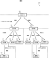
- the multiple devices 100 included in the air conditioning system 1000 are connected in a tree structure.
- Cloud server 110 is the root node.
- System controller 120 is a child node with cloud server 110 as the parent node.
- Outdoor units 131 and 132 are child nodes with system controller 120 as the parent node.
- Indoor units 141, 142, and individual controller 143 are child nodes with outdoor unit 131 as the parent node.
- Indoor units 144, 145, and individual controller 146 are child nodes with outdoor unit 132 as the parent node.
- Individual controller 151 is a child node with indoor unit 141 as the parent node.
- Communication adapter 152 is a child node with indoor unit 145 as the parent node.
- a parent node authenticates a child node. That is, an authentication device provided in each of the multiple networks 200 authenticates a device 100 that corresponds to a child node from the perspective of the authentication device itself.
- the cloud server 110 which is a first authentication device, authenticates the system controller 120 in the network 210, which is the first network.
- the system controller 120 which is a second authentication device, authenticates the outdoor units 131 and 132 in the network 220, which is the second network.
- the outdoor unit 131 which is a third authentication device, authenticates the indoor units 141, 142, and individual controller 143 within network 231, which is the third network.
- the outdoor unit 132 which is a third authentication device, authenticates the indoor units 144, 145, and individual controller 146 within network 232, which is the third network.
- the indoor unit 141 which is a fourth authentication device, authenticates the individual controller 151 within network 241, which is the fourth network.
- the indoor unit 145 which is a fourth authentication device, authenticates the communication adapter 152 within network 242, which is the fourth network.
- devices 100 belonging to both the upper network 200 and the lower network 200 are devices to be authenticated in the upper network 200, and are authenticating devices in the lower network 200.
- the outdoor unit 131 is a device to be authenticated in the network 220, and is an authenticating device in the network 231.
- the indoor unit 141 is a device to be authenticated in the network 231, and is an authenticating device in the network 241.
- the authenticating device authenticates the authenticated device based on authentication-related information written to the memory unit 12 of the device 100 when the device 100 is shipped.
- FIG. 5 shows the authentication-related information.
- the authentication-related information includes a CA (Certificate Authority) certificate, a device certificate, a device private key, and a device public key.
- the CA certificate is a certificate common to all manufacturers and is used to verify the device certificate.
- the CA certificate is created by the manufacturer and written to the memory unit 12 of each device 100 when the device 100 is shipped from the factory.
- the CA certificate includes a CA public key. Information encrypted with the CA private key can be decrypted with the CA public key.
- the device certificate is a certificate unique to the device 100, and includes a device public key signed with a CA private key.
- the device certificate is created by the manufacturer and written to the memory unit 12 of the device 100 when the device 100 is shipped from the factory.
- the device private key is a private key unique to the device 100.
- the device public key is a public key unique to the device 100. Information encrypted with the device public key can be decrypted with the device private key.
- the device private key and device public key are created by the device 100 itself, and written to the memory unit 12 of the device 100 when the device 100 is shipped from the factory.
- the authenticating device authenticates the authenticated device by verifying the device certificate of the authenticated device obtained from the authenticated device with the CA certificate held by the authenticating device.
- the authentication process executed by the air conditioning system 1000 will be described below with reference to FIG. 6. Note that FIG. 6 shows sequences related to the cloud server 110, system controller 120, outdoor unit 131, indoor unit 141, and individual controller 151, and omits sequences related to other devices.
- the cloud server 110, the system controller 120, the outdoor unit 131, the indoor unit 141, and the individual controller 151 each start device authentication in response to the occurrence of a device authentication trigger.
- the device authentication trigger is set for each device 100, for example, and it is possible for each device 100 in each network to proceed with device authentication completely in parallel. Therefore, the order in which device authentication is started is not limited to the example shown in FIG. 6.
- device authentication of the outdoor unit 131 by the system controller 120 may be executed after device authentication of the individual controller 151 by the indoor unit 141.
- Possible device authentication triggers include a user operation on a user interface, a trigger based on plug and play, etc.
- Possible user operations include a user operation on an operation reception unit 14 equipped with a touch screen, dip switches, etc.
- step ST111 the cloud server 110 requests the system controller 120 for the system controller 120's device certificate. Meanwhile, in step ST122, the system controller 120 transmits the system controller 120's device certificate to the cloud server 110. In step ST113, the cloud server 110 verifies the device certificate received from the system controller 120 with the CA certificate held by the cloud server 110.
- the cloud server 110 decrypts the device public key, which is included in the device certificate and signed with the CA private key, using the CA public key included in the CA certificate. If the cloud server 110 is successful in decrypting the device public key using the CA public key, it determines that the device certificate is a legitimate certificate and that the system controller 120 is a legitimate device 100. If the cloud server 110 is unsuccessful in decrypting the device public key using the CA public key, it determines that the device certificate is an invalid certificate and that the system controller 120 is an invalid device 100.
- step ST121 the system controller 120 requests the outdoor unit 131 for its device certificate from the outdoor unit 131. Meanwhile, in step ST132, the outdoor unit 131 transmits its device certificate to the system controller 120. In step ST123, the system controller 120 verifies the device certificate received from the outdoor unit 131 with the CA certificate held by the system controller 120.
- the system controller 120, outdoor unit 131, indoor unit 141, etc. verify the device certificate with the CA certificate using a method similar to that used by the cloud server 110. Although not shown in the figure, the system controller 120 also requests a device certificate from the outdoor unit 132, and verifies the device certificate obtained from the outdoor unit 132 with the CA certificate.
- step ST131 the outdoor unit 131 requests the indoor unit 141's device certificate from the indoor unit 141. Meanwhile, in step ST142, the indoor unit 141 transmits the indoor unit 141's device certificate to the outdoor unit 131. In step ST133, the outdoor unit 131 verifies the device certificate received from the indoor unit 141 with the CA certificate held by the outdoor unit 131.
- the outdoor unit 131 also requests device certificates from the indoor unit 142 and the individual controller 143, and verifies the device certificates obtained from the indoor unit 142 and the individual controller 143 with the CA certificate.
- the outdoor unit 132 also requests device certificates from the indoor unit 144, the indoor unit 145, and the individual controller 146, and verifies the device certificates obtained from the indoor unit 144, the indoor unit 145, and the individual controller 146 with the CA certificate.
- step ST141 the indoor unit 141 requests the individual controller 151 for its device certificate from the individual controller 151. Meanwhile, in step ST152, the individual controller 151 transmits its device certificate to the indoor unit 141. In step ST143, the indoor unit 141 verifies the device certificate received from the individual controller 151 with the CA certificate held by the indoor unit 141. Although not shown in the figure, the indoor unit 145 requests a device certificate from the communication adapter 152 and verifies the device certificate obtained from the communication adapter 152 with the CA certificate.
- the authentication device transmits the authentication result from its own device and the authentication result acquired from the child node to the parent node.
- the indoor unit 141 transmits the authentication result for the individual controller 151 to the outdoor unit 131.
- the indoor unit 145 transmits the authentication result for the communication adapter 152 to the outdoor unit 132.
- the outdoor unit 131 transmits the authentication results for the indoor unit 141, indoor unit 142, individual controller 143, and individual controller 151 to the system controller 120.
- the outdoor unit 132 transmits the authentication results for the indoor units 144, 145, the individual controller 146, and the communication adapter 152 to the system controller 120.
- the system controller 120 transmits the authentication results for the outdoor units 131, 132, the indoor units 141, 142, the individual controller 143, the indoor units 144, 145, the individual controller 146, the individual controller 151, and the communication adapter 152 to the cloud server 110.
- all authentication results are supplied to the cloud server 110, which is the root node.
- encrypted communication is performed between the authenticated devices 100.
- the authentication device generates a pair of a network public key and a network private key.
- the authentication device encrypts the network certificate signed with the authenticating device's device private key and the network private key with the device public key of the authenticated device, and sends it to the authenticated device.
- the authenticated device decrypts the encrypted network certificate and network private key with the authenticated device's device private key.
- the network certificate contains the network public key.
- the authentication device and authenticated device perform encrypted communication based on the network certificate, for example, in accordance with the Datagram Transport Layer Security (DTLS) protocol.
- DTLS Datagram Transport Layer Security
- each of the multiple networks 200 included in the air conditioning system 1000 includes an authentication device that authenticates other devices that belong to the network 200 to which the local device belongs.
- an authentication device is provided for each network 200, and device authentication is performed for each network 200. Therefore, in this embodiment, authentication sequences in the multiple networks 200 can be performed in parallel.
- the time required for device authentication of the entire air conditioning system 1000 is shorter than in a configuration in which a single device 100, such as the cloud server 110 or the system controller 120, authenticates all of the other devices 100.
- the time required for authentication of the devices 100 included in the air conditioning system 1000 can be shortened. Note that each authentication device does not need to have high processing power because it does not need to authenticate devices 100 that belong to a network 200 to which the device does not belong.
- a second authentication device that belongs to both the first network and the second network and authenticates other devices that belong to the second network is authenticated by the first authentication device that belongs to the first network.
- a third authentication device that belongs to both the second network and the third network and authenticates other devices that belong to the third network is authenticated by the second authentication device that belongs to the second network.
- authentication devices other than the first authentication device are authenticated by the other authentication devices. Therefore, according to this embodiment, it is possible to authenticate all devices 100 other than the first authentication device, which is the base point of authentication.
- the first authenticated device is the cloud server 110
- the second authenticated device is the system controller 120.
- the cloud server 110 is a device 100 that is less likely to be spoofed and is more reliable than the system controller 120. For this reason, it is believed that no particular problem will arise if the cloud server 110 is not authenticated by other devices.
- the system controller 120 is authenticated by the cloud server 110. Therefore, according to this embodiment, improved security can be expected.
- the multiple devices 100 in the air conditioning system 1000 are connected in a tree structure, and the authentication devices in each of the multiple networks 200 authenticate the devices 100 that correspond to child nodes from the perspective of the device itself.
- a chain of device authentication is established in which the parent node authenticates the child node with the root node as the base point. Therefore, according to this embodiment, all devices 100 other than the root node are properly authenticated.
- the authentication sequence in each network 200 is independent, and it is possible to employ an authentication sequence that is not dependent on the device configuration, network configuration, etc.
- the first authentication device which is the base point of device authentication, authenticates other devices that belong to the first network to which the first authentication device belongs. If the first authentication device belongs to multiple first networks, the first authentication device authenticates other devices that belong to each first network. If the authenticated device that has been authenticated by the first authentication device also belongs to a second network to which the first authentication device does not belong, it authenticates other devices that belong to the second network as the second authentication device.
- the authenticated device that has been authenticated by the second authentication device also belongs to a third network to which the second authentication device does not belong, it authenticates other devices that belong to the third network as a third authentication device. After that, using a similar procedure, the authenticated device that has been authenticated by the authentication device authenticates the other devices as an authenticating device if there are other devices that it should authenticate. With this configuration, all devices 100 other than the first authentication device, which is the base point for device authentication, are authenticated.
- Embodiment 2 In the first embodiment, an example in which device authentication is performed based on the cloud server 110, which is difficult to spoof and highly reliable, has been described. In the present embodiment, an example in which device authentication is performed based on the refrigerant system device 100, which is difficult to spoof and highly reliable, in a case in which such a cloud server 110 does not exist, will be described. Note that descriptions of configurations and functions similar to those in the first embodiment will be omitted or simplified as appropriate.
- FIG. 7 is a diagram showing the configuration of an air conditioning system 1200 according to this embodiment.
- the air conditioning system 1200 includes a system controller 120, an outdoor unit 131, an outdoor unit 132, an indoor unit 141, an indoor unit 142, an individual controller 143, an indoor unit 144, an indoor unit 145, an individual controller 146, an individual controller 151, and a communication adapter 152.
- the air conditioning system 1200 does not include a cloud server 110 that is difficult to spoof and highly reliable. Therefore, in this embodiment, equipment authentication is performed based on the refrigerant system equipment 100 that is difficult to spoof and considered to be highly reliable among the equipment 100 included in the air conditioning system 1200.
- the refrigerant system equipment 100 includes outdoor unit 131, outdoor unit 132, indoor unit 141, indoor unit 142, indoor unit 144, indoor unit 145, etc.
- the outdoor unit is adopted as the base point for equipment authentication.
- the outdoor unit 131 and the outdoor unit 132 are adopted as the base points for equipment authentication.
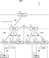
- the multiple devices 100 included in the air conditioning system 1200 are connected in a tree structure, and the root node is the system controller 120.
- the outdoor unit 131 which is the first authentication device, authenticates the system controller 120 in network 220, which is the first network.
- the outdoor unit 131 authenticates the indoor units 141, 142, and the individual controller 143 in network 231, which is the first network.
- the outdoor unit 132 which is the first authentication device, authenticates the system controller 120 in network 220, which is the first network.
- the outdoor unit 132 authenticates the indoor units 144, 145, and the individual controller 146 in network 232, which is the first network.
- the indoor unit 141 which is the second authentication device, authenticates the individual controller 151 in network 241, which is the second network.
- the indoor unit 145 which is the second authentication device, authenticates the communication adapter 152 in network 242, which is the second network.
- the authenticating device authenticates the authenticated device by verifying the device certificate of the authenticated device obtained from the authenticated device with the CA certificate held by the authenticating device.
- the authentication process executed by the air conditioning system 1200 will be described below with reference to FIG. 9. Note that FIG. 9 shows the sequence relating to the system controller 120, outdoor unit 131, indoor unit 141, and individual controller 151, and omits the sequences relating to other devices.
- the outdoor unit 131 which is the first authenticated device and the starting point of device authentication, starts device authentication in response to the occurrence of a device authentication trigger.
- the outdoor unit 131 requests the system controller 120 for its device certificate in step ST231A.
- the system controller 120 transmits the system controller 120's device certificate to the outdoor unit 131 in step ST222.
- the outdoor unit 131 verifies the device certificate received from the system controller 120 with the CA certificate held by the outdoor unit 131.
- step ST231B the outdoor unit 131 requests the indoor unit 141's device certificate from the indoor unit 141.
- the indoor unit 141 transmits the indoor unit 141's device certificate to the outdoor unit 131.
- step ST233B the outdoor unit 131 verifies the device certificate received from the indoor unit 141 with the CA certificate held by the outdoor unit 131.
- the outdoor unit 131 also requests device certificates from the indoor unit 142 and the individual controller 143, and verifies the device certificates obtained from the indoor unit 142 and the individual controller 143 with the CA certificate.
- the outdoor unit 131 may authenticate the outdoor unit 132.
- step ST241 the indoor unit 141 requests the individual controller 151 for its device certificate from the individual controller 151. Meanwhile, in step ST252, the individual controller 151 transmits its device certificate to the indoor unit 141. In step ST243, the indoor unit 141 verifies the device certificate received from the individual controller 151 with the CA certificate held by the indoor unit 141.
- the authentication result is supplied to, for example, the outdoor unit 131, which is the device 100 that is the base point of the device authentication. That is, in step ST244, the indoor unit 141 transmits the authentication result for the individual controller 151 to the outdoor unit 131. This allows the outdoor unit 131 to obtain all authentication results of the device authentication based on the outdoor unit 131.
- the method of device authentication based on the outdoor unit 132 is the same as the method of device authentication based on the outdoor unit 131. After device authentication based on the outdoor unit 131 and device authentication based on the outdoor unit 132 are completed, encrypted communication is performed between the authenticated devices 100.
- the refrigerant-system equipment 100 which is difficult to spoof and highly reliable, is the base point of equipment authentication. Therefore, according to this embodiment, the refrigerant-system equipment 100, which is difficult to spoof and highly reliable, is prevented from being subjected to improper operation by equipment 100, which is easy to spoof and less reliable.
- the outdoor units 131 and 132 are the first authenticated equipment, which is the base point of equipment authentication. According to this embodiment, spoofing of the indoor units 141, 142, 144, and 145 can be detected.
- the first authentication device which is the refrigerant system device 100 that is difficult to spoof and highly reliable, or the second authentication device authenticated by the first authentication device, authenticates the system controller 120 that is easy to spoof and has low reliability. Therefore, according to this embodiment, the refrigerant system device 100 is prevented from being subjected to improper operations by the system controller 120.
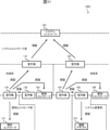
- equipment authentication is performed with the outdoor unit 131 as the base point of equipment authentication.
- the outdoor unit 131 which is the first authentication device, authenticates the system controller 120 and the outdoor unit 132 in the network 220, which is the first network.
- the outdoor unit 131 authenticates the indoor units 141, 142, and the individual controller 143 in the network 231, which is the first network.
- the outdoor unit 132 which is the second authentication device, authenticates the indoor units 144, 145, and the individual controller 146 in the network 232, which is the second network.
- the indoor unit 141 which is the second authentication device, authenticates the individual controller 151 in the network 241, which is the second network.
- the indoor unit 145 which is the third authentication device, authenticates the communication adapter 152 in the network 242, which is the third network.
- the outdoor unit 131 is the first authenticated device that is the base point for device authentication. According to this embodiment, counterfeiting of the outdoor unit 132, indoor unit 141, indoor unit 142, indoor unit 144, and indoor unit 145 can be detected.
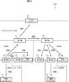
- equipment authentication is performed with the indoor units 141 and 144 as the base points of equipment authentication.
- the indoor unit 141 which is the first authenticated device, authenticates the outdoor unit 131, the indoor unit 142, and the individual controller 143 within the network 231, which is the first network.
- the indoor unit 141 which is the first authenticated device, authenticates the individual controller 151 within the network 241, which is the first network.
- the outdoor unit 131 which is the second authenticated device, authenticates the system controller 120 within the network 220, which is the second network.
- the indoor unit 144 which is the first authentication device, authenticates the outdoor unit 132, the indoor unit 145, and the individual controller 146 within the first network, network 232.
- the outdoor unit 132 which is the second authentication device, authenticates the system controller 120 within the second network, network 220.
- the indoor unit 145 which is the second authentication device, authenticates the communication adapter 152 within the second network, network 242.
- the indoor unit 141 and the indoor unit 144 are the first authenticated equipment that is the base point of equipment authentication. According to this embodiment, counterfeiting of the outdoor unit 131, the outdoor unit 132, the indoor unit 142, and the indoor unit 145 can be detected.
- equipment authentication is performed with the indoor unit 141 as the base point of equipment authentication.
- the indoor unit 141 which is the first authentication device, authenticates the outdoor unit 131, the indoor unit 142, and the individual controller 143 within network 231, which is the first network.
- the indoor unit 141 which is the first authentication device, authenticates the individual controller 151 within network 241, which is the first network.
- the outdoor unit 131 which is the second authentication device, authenticates the system controller 120 and the outdoor unit 132 within network 220, which is the second network.
- the outdoor unit 132 which is a third authenticated device, authenticates the indoor units 144, 145, and the individual controller 146 within the network 232, which is the third network.
- the indoor unit 145 which is a fourth authenticated device, authenticates the communication adapter 152 within the network 242, which is the fourth network.
- the indoor unit 141 is the base point for equipment authentication. According to this embodiment, counterfeiting of the outdoor unit 131, the outdoor unit 132, the indoor unit 142, the indoor unit 144, and the indoor unit 145 can be detected.
- the multiple devices 100 included in the air conditioning system 1600 are connected in a tree structure with the system controller 120 as the root node.
- the parent node authenticates the child node
- the child node authenticates the parent node. That is, the system controller 120 authenticates the outdoor units 131 and 132 within the network 220. Also, the outdoor units 131 and 132 authenticate the system controller 120 within the network 220.
- the outdoor unit 131 authenticates the indoor units 141, 142, and individual controller 143 within the network 231.
- the indoor units 141, 142, and individual controller 143 authenticate the outdoor unit 131 within the network 231.
- the outdoor unit 132 authenticates the indoor units 144, 145, and individual controller 146 within the network 232.
- the indoor units 144, 145, and individual controller 146 authenticate the outdoor unit 132 within the network 232.
- the indoor unit 141 authenticates the individual controller 151 within the network 241.
- the individual controller 151 authenticates the indoor unit 141 within the network 241.
- the indoor unit 145 authenticates the communication adapter 152 within the network 242.
- the communication adapter 152 authenticates the indoor unit 145 within the network 242.
- FIG. 14 shows sequences relating to the system controller 120, outdoor unit 131, indoor unit 141, and individual controller 151, and omits sequences relating to other devices.
- step ST321 the system controller 120 requests the outdoor unit 131 for its device certificate from the outdoor unit 131. Meanwhile, in step ST332A, the outdoor unit 131 transmits its device certificate to the system controller 120. In step ST323, the system controller 120 verifies the device certificate received from the outdoor unit 131 with the CA certificate held by the system controller 120.
- step ST331B the outdoor unit 131 requests the system controller 120 for its device certificate from the system controller 120. Meanwhile, in step ST322B, the system controller 120 transmits the system controller 120's device certificate to the outdoor unit 131. In step ST333B, the outdoor unit 131 verifies the device certificate received from the system controller 120 with the CA certificate held by the outdoor unit 131. Although not shown in the figure, the system controller 120 and the outdoor unit 132 authenticate each other.
- step ST331A the outdoor unit 131 requests the indoor unit 141's device certificate from the indoor unit 141.
- step ST342A the indoor unit 141 transmits the indoor unit 141's device certificate to the outdoor unit 131.
- step ST333A the outdoor unit 131 verifies the device certificate received from the indoor unit 141 with the CA certificate held by the outdoor unit 131.
- step ST341B the indoor unit 141 requests the outdoor unit 131 for its device certificate from the outdoor unit 131. Meanwhile, in step ST332B, the outdoor unit 131 transmits its device certificate to the indoor unit 141. In step ST343B, the indoor unit 141 verifies the device certificate received from the outdoor unit 131 with the CA certificate held by the indoor unit 141.
- mutual authentication is also performed between the outdoor unit 131 and the indoor unit 142, between the outdoor unit 131 and the individual controller 143, between the outdoor unit 132 and the indoor unit 144, between the outdoor unit 132 and the indoor unit 145, and between the outdoor unit 132 and the individual controller 146.
- step ST341A the indoor unit 141 requests the individual controller 151 for its device certificate from the individual controller 151. Meanwhile, in step ST352, the individual controller 151 transmits its device certificate to the indoor unit 141. In step ST343A, the indoor unit 141 verifies the device certificate received from the individual controller 151 with the CA certificate held by the indoor unit 141.
- step ST351 the individual controller 151 requests the indoor unit 141's device certificate from the indoor unit 141.
- step ST342B the indoor unit 141 transmits the indoor unit 141's device certificate to the individual controller 151.
- step ST353 the individual controller 151 verifies the device certificate received from the indoor unit 141 with the CA certificate held by the individual controller 151.
- the indoor unit 145 and the communication adapter 152 authenticate each other.
- the authentication result is supplied to the system controller 120, which is the root node, for example.
- the individual controller 151 transmits the authentication result for the indoor unit 141 to the indoor unit 141.
- the communication adapter 152 transmits the authentication result for the indoor unit 145 to the indoor unit 145.
- the indoor unit 141 transmits the authentication result for the indoor unit 141 and the individual controller 151 to the outdoor unit 131.
- the indoor unit 145 transmits the authentication result for the indoor unit 145 and the communication adapter 152 to the outdoor unit 132.
- the outdoor unit 131 transmits the authentication results for the outdoor unit 131, the indoor unit 141, the indoor unit 142, the individual controller 143, and the individual controller 151 to the system controller 120.
- the outdoor unit 132 transmits the authentication results for the outdoor unit 132, the indoor unit 144, the indoor unit 145, the individual controller 146, and the communication adapter 152 to the system controller 120.
- all authentication results are supplied to the system controller 120, which is the root node. Thereafter, encrypted communication is performed between the authenticated devices 100.
- the trigger with which the authenticating device of each network 200 starts authenticating the authenticated device can be adjusted as appropriate.
- the authenticating device of each network 200 may start authenticating the authenticated device in response to a request from a specific device 100 among the multiple devices 100 included in the air conditioning system 1000.
- the authenticating device of each network 200 may start authenticating the authenticated device spontaneously. In this way, the direction of device authentication and the order in which device authentication is performed do not have to match.
- the configuration of the air conditioning system is not limited to that shown in embodiments 1-6.
- the indoor unit 141 may be connected to the system controller 120 instead of the outdoor unit 131 in the network 220, and the indoor unit 141 and the outdoor unit 131 may be connected in the network 231.
- the indoor unit 141 is authenticated by the system controller 120, and in the network 231, the outdoor unit 131 is authenticated by the indoor unit 141.
- the first authentication device that serves as the base point for device authentication is not limited to the device 100 shown in embodiment 1-6.
- the outdoor unit 132 or the indoor unit 144 may be set alone as the first authentication device, or at least one device 100 among the system controller 120, the indoor unit 142, the individual controller 143, the indoor unit 145, the individual controller 146, the individual controller 151, and the communication adapter 152 may be set as the first authentication device.
- each network 200 Although multiple authentication devices may be provided in each network 200, it is preferable that one authentication device is provided in each network 200.
- the method of determining one authentication device in each network 200 can be adjusted as appropriate. It is preferable that the authentication device is a device 100 that always exists and is uniquely determined in each network 200. For example, in each network 200, the device 100 with the smallest network address, the device 100 supplying power to other devices in the network 200, etc. may be determined to be the authentication device.
- This disclosure is applicable to air conditioning systems equipped with multiple devices, including outdoor units and indoor units.
Landscapes
- Engineering & Computer Science (AREA)
- General Engineering & Computer Science (AREA)
- Human Computer Interaction (AREA)
- Computer Security & Cryptography (AREA)
- Mechanical Engineering (AREA)
- Combustion & Propulsion (AREA)
- Chemical & Material Sciences (AREA)
- Theoretical Computer Science (AREA)
- Software Systems (AREA)
- General Physics & Mathematics (AREA)
- Physics & Mathematics (AREA)
- Computer Hardware Design (AREA)
- Air Conditioning Control Device (AREA)
Abstract
空気調和システムは、室外機と室内機とを含む複数の機器(100A、100B、100C、100D、100E、100F、100G)を備える。複数の機器(100A、100B、100C、100D、100E、100F、100G)のそれぞれは、複数のネットワーク(200A、200B、200C)のうち少なくとも1つのネットワークに属する。複数のネットワーク(200A、200B、200C)のそれぞれは、自機器が属するネットワークに属する他の機器を認証する認証機器を備える。
Description
本開示は、空気調和システム、及び、認証方法に関する。
近年、室外機と室内機とを備える空気調和システムがサイバー攻撃の対象となる事例が発生している。このため、空気調和システムに対して、サイバー攻撃に対するセキュリティ対策が望まれている。セキュリティ対策としては、例えば、空気調和システムが備える各機器が正当な機器であることを確認する機器認証がある。
このような機器認証に関する技術は、例えば、特許文献1に記載されている。特許文献1には、空調機が備える室外機が、空調機を操作するためのシステムコントローラを認証する空気調和システムが記載されている。
しかしながら、特許文献1に記載された技術では、空気調和システムが備える機器のうちシステムコントローラ以外の機器が認証されないため、セキュリティ対策としては不十分である。ここで、例えば、空気調和システムが備える1つの機器が、他の全ての機器を認証すると、機器認証に要する時間が膨大になる。このため、空気調和システムが備える機器の認証に要する時間を短縮する技術が望まれている。
本開示は、上記問題に鑑みてなされたものであり、空気調和システムが備える機器の認証に要する時間を短縮する空気調和システム、及び、認証方法を提供することを目的とする。
上記目的を達成するために、本開示に係る空気調和システムは、
室外機と室内機とを含む複数の機器を備える空気調和システムであって、
前記複数の機器のそれぞれは、複数のネットワークのうち少なくとも1つのネットワークに属し、
前記複数のネットワークのそれぞれは、自機器が属するネットワークに属する他の機器を認証する認証機器を備える。
室外機と室内機とを含む複数の機器を備える空気調和システムであって、
前記複数の機器のそれぞれは、複数のネットワークのうち少なくとも1つのネットワークに属し、
前記複数のネットワークのそれぞれは、自機器が属するネットワークに属する他の機器を認証する認証機器を備える。
本開示では、複数のネットワークのそれぞれが、自機器が属するネットワークに属する他の機器を認証する認証機器を備える。従って、本開示によれば、空気調和システムが備える機器の認証に要する時間を短縮することができる。
以下、本開示の実施の形態について、図面を参照しながら詳細に説明する。なお、図中同一又は相当部分には同一符号を付す。
(実施の形態1)
図1は、本実施の形態に係る空気調和システム1000の構成を示す図である。空気調和システム1000は、ビル、マンション、アパート、工場等の内部の空気を調和するためのシステムである。空気調和システム1000は、空気調和システム1000が備える各機器を認証する機能を有する。機器の認証は、機器が正当な機器と不当な機器との何れであるかを確認することである。
図1は、本実施の形態に係る空気調和システム1000の構成を示す図である。空気調和システム1000は、ビル、マンション、アパート、工場等の内部の空気を調和するためのシステムである。空気調和システム1000は、空気調和システム1000が備える各機器を認証する機能を有する。機器の認証は、機器が正当な機器と不当な機器との何れであるかを確認することである。
正当な機器は、例えば、なりすましにより偽装されていない機器であり、信頼できる機器である。不当な機器は、例えば、なりすましにより偽装された機器であり、信頼できない機器である。空気調和システム1000は、クラウドサーバ110と、システムコントローラ120と、室外機131と、室外機132と、室内機141と、室内機142と、個別コントローラ143と、室内機144と、室内機145と、個別コントローラ146と、個別コントローラ151と、通信アダプタ152とを備える。
クラウドサーバ110は、クラウドコンピューティングにおけるリソースを提供するサーバであり、空気調和処理に関するサービスを提供するサーバである。本実施の形態では、クラウドサーバ110は、システムコントローラ120を介して、空気調和システム1000が備える各機器を遠隔から制御又は監視する。
システムコントローラ120は、空気調和システム1000の全体の動作を制御する機器である。なお、クラウドサーバ110とシステムコントローラ120とは、通信回線311と通信回線312とのうち少なくとも一方を介して相互に接続される。つまり、クラウドサーバ110とシステムコントローラ120とは、通信回線311を介して相互に接続されてもよいし、ブロードバンドルータ500により相互に接続された通信回線311及び通信回線312を介して相互に接続されてもよい。
通信回線311は、インターネット、電話網等である。この電話網は、LTE(Long Term Evolution)、4G(4th Generation)、5G(5th Generation)等に対応した電話網である。通信回線312は、例えば、ビル、マンション、アパート、工場等に設けられたLAN(Local Area Network)用の回線である。クラウドサーバ110とシステムコントローラ120と通信回線311と通信回線312とは、ネットワーク210を構成する。ネットワーク210は、空気調和システム1000が備える機器のうち遠隔操作に用いる機器が接続されたネットワークである。以下、適宜、ネットワーク210を遠隔操作系といい、ネットワーク210を用いた通信を遠隔操作系通信という。
室外機131と室外機132とは、室内の空気を調和する設備機器のうち室外に設置される設備機器である。室内の空気を調和することは、室内の空気の温度、湿度、空気清浄度等を調整することである。室内機141と室内機142と室内機144と室内機145とは、室内の空気を調和する設備機器のうち室内に設置される設備機器である。室内機141と室内機142と室内機144と室内機145とは、暖房、冷房、除湿、送風等のための空気を室内に吹き出す。室外機131は、冷媒配管(図示せず)を介して、室内機141及び室内機142との間で冷媒を循環させる。室外機132は、冷媒配管(図示せず)を介して、室内機144及び室内機145との間で冷媒を循環させる。
個別コントローラ143は、自機器が属するネットワーク231に属する機器を制御するためのコントローラである。つまり、個別コントローラ143は、室外機131と室内機141と室内機142とを制御するためのコントローラである。個別コントローラ146は、自機器が属するネットワーク232に属する機器を制御するためのコントローラである。つまり、個別コントローラ146は、室外機132と室内機144と室内機145とを制御するためのコントローラである。
システムコントローラ120と室外機131と室外機132とは、通信回線320を介して相互に接続される。通信回線320は、システムコントローラ120と空気調和装置とを接続するための回線である。本実施の形態では、システムコントローラ120と接続される空気調和装置は、室外機131と室外機132との2つの空気調和装置である。システムコントローラ120と室外機131と室外機132と通信回線320とは、ネットワーク220を構成する。ネットワーク220は、システムコントローラ120と空気調和装置とが接続されたネットワークである。以下、適宜、ネットワーク220をシステムコントローラ系といい、ネットワーク220を用いた通信をシステムコントローラ系通信という。
室外機131と室内機141と室内機142と個別コントローラ143とは、通信回線331を介して相互に接続される。室外機132と室内機144と室内機145と個別コントローラ146とは、通信回線332を介して相互に接続される。通信回線331と通信回線332とのそれぞれは、同一の冷媒系統内の機器を接続するための回線である。
室外機131と室内機141と室内機142と個別コントローラ143と通信回線331とは、ネットワーク231を構成する。室外機132と室内機144と室内機145と個別コントローラ146と通信回線332とは、ネットワーク232を構成する。ネットワーク231とネットワーク232とのそれぞれは、同一の冷媒系統内の機器が接続されたネットワークである。以下、適宜、ネットワーク231及びネットワーク232を冷媒系といい、ネットワーク231又はネットワーク232を用いた通信を冷媒系通信という。
個別コントローラ151は、自機器に接続された機器を制御するためのコントローラである。つまり、個別コントローラ151は、室内機141を制御するためのコントローラである。室内機141と個別コントローラ151とは、通信回線341を介して相互に接続される。通信回線341は、室内機141と個別コントローラ151とを接続するための回線である。室内機141と個別コントローラ151と通信回線341とは、ネットワーク241を構成する。ネットワーク241は、室内機141と個別コントローラ151とが接続されたネットワークである。以下、適宜、ネットワーク241を個別コントローラ系といい、ネットワーク241を用いた通信を個別コントローラ系通信という。
通信アダプタ152は、自機器に接続された機器が属するシステムを拡張するための通信アダプタである。つまり、通信アダプタ152は、室内機145が属する空気調和システム1000を拡張するための通信アダプタである。室内機145と通信アダプタ152とは、通信回線342を介して相互に接続される。通信回線342は、室内機145と通信アダプタ152とを接続するための回線である。室内機145と通信アダプタ152と通信回線342とは、ネットワーク242を構成する。
ネットワーク242は、室内機145と通信アダプタ152とが接続されたネットワークである。以下、適宜、ネットワーク242をシステム拡張系といい、ネットワーク242を用いた通信をシステム拡張系通信という。なお、通信アダプタ152は、ネットワーク232と図示しないネットワークとを接続する機能を有する。従って、通信アダプタ152は、図示しないネットワークに属する図示しない機器にも接続される。
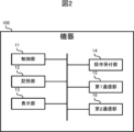
以上、説明したように、空気調和システム1000は、空気調和システム1000が備える複数のネットワークのうち少なくとも1つのネットワークに属する複数の機器100を備える。機器100は、室外機131と室外機132と室内機141と室内機142と個別コントローラ143と室内機144と室内機145と個別コントローラ146と個別コントローラ151と通信アダプタ152の総称である。図2に示すように、機器100は、例えば、制御部11と、記憶部12と、表示部13と、操作受付部14と、第1通信部15と、第2通信部16とを備える。
制御部11は、CPU(Central Processing Unit)、ROM(Read Only Memory)、RAM(Random Access Memory)、RTC(Real Time Clock)等を備える。CPUは、中央処理装置、中央演算装置、プロセッサ、マイクロプロセッサ、マイクロコンピュータ、DSP(Digital Signal Processor)等とも呼び、機器100の制御に係る処理及び演算を実行する中央演算処理部として機能する。制御部11において、CPUは、ROMに格納されているプログラム及びデータを読み出し、RAMをワークエリアとして用いて、機器100を統括制御する。RTCは、例えば、計時機能を有する集積回路である。なお、CPUは、RTCから読み出される時刻情報から現在日時を特定可能である。
記憶部12は、フラッシュメモリ、EPROM(Erasable Programmable ROM)、EEPROM(Electrically Erasable Programmable ROM)等の不揮発性の半導体メモリを備えており、いわゆる補助記憶装置としての役割を担う。記憶部12は、制御部11が各種処理を実行するために使用するプログラム及びデータを記憶する。また、記憶部12は、制御部11が各種処理を実行することにより生成又は取得するデータを記憶する。
表示部13は、制御部11による制御に従って、各種の画像を表示する。例えば、表示部13は、ユーザから各種の操作を受け付けるための画面を表示する。表示部13は、タッチスクリーン、液晶ディスプレイ等を備える。操作受付部14は、ユーザから各種の操作を受け付け、受け付けた操作の内容を示す情報を制御部11に供給する。操作受付部14は、タッチスクリーン、ボタン、レバー等を備える。
第1通信部15は、制御部11による制御に従って、あるネットワークに接続された機器100と通信する。第2通信部16は、制御部11による制御に従って、他のネットワークに接続された機器100と通信する。第1通信部15と第2通信部16とは、各種の有線通信規格又は各種の無線通信規格に則って、機器100と通信する。無線通信規格としては、Wi-Fi(登録商標)、Bluetooth(登録商標)、Zigbee(登録商標)、LTE(Long Term Evolution)、4G(4th Generation)、5G(5th Generation)等がある。有線通信規格としては、イーサネット(登録商標)、USB(Universal Serial Bus、登録商標)、Thunderbolt(登録商標)等がある。第1通信部15と第2通信部16とは、各種の通信規格に準拠した通信インターフェースを備える。
なお、機器100は、制御部11と、記憶部12と、表示部13と、操作受付部14と、第1通信部15と、第2通信部16との全てを備えていなくてもよい。例えば、機器100は、表示部13を備えていなくてもよいし、操作受付部14を備えていなくてもよいし、第1通信部15を備えていなくてもよいし、第2通信部16を備えていなくてもよい。
次に、図3を参照して、空気調和システム1000で採用される各機器100の認証手順について説明する。
まず、本実施の形態では、空気調和システム1000が備える複数の機器100のそれぞれは、空気調和システム1000が備える複数のネットワーク200のうち少なくとも1つのネットワーク200に属する。ネットワーク200は、ネットワーク210とネットワーク220とネットワーク231とネットワーク232とネットワーク241とネットワーク242との総称である。そして、複数のネットワーク200のそれぞれは、自機器が属するネットワーク200に属する他の機器を認証する認証機器と、認証機器により認証される被認証機器とを備える。本実施の形態では、ネットワーク200を跨ぐ機器100の認証が実施されず、ネットワーク200内で機器100の認証が完結する。つまり、本実施の形態では、ネットワーク200毎に機器100の認証が実行される。
本実施の形態では、空気調和システム1000が備える複数のネットワーク200は、第1ネットワークと第2ネットワークと第3ネットワークとを含み、空気調和システム1000が備える複数の機器100は、第1認証機器と第2認証機器と第3認証機器とを含む。第1認証機器は、第1ネットワークに属し、第1ネットワークに属する他の機器を認証する。第2認証機器は、第1ネットワークと第2ネットワークとに属し、第1認証機器により認証され、第2ネットワークに属する他の機器を認証する。第3認証機器は、第2ネットワークと第3ネットワークとに属し、第2認証機器により認証され、第3ネットワークに属する他の機器を認証する。
例えば、図3に示すように、ネットワーク200Aにおいて機器100Aと機器100Bと機器100Cとが通信回線300Aにより接続され、ネットワーク200Bにおいて機器100Bと機器100Dと機器100Eとが通信回線300Bにより接続され、ネットワーク200Cにおいて機器100Dと機器100Fと機器100Gとが通信回線300Cにより接続される場合を想定する。以下、適宜、通信回線300Aと通信回線300Bと通信回線300Cとを総称して通信回線300という。この場合、ネットワーク200Aでは、機器100Aが、機器100Bと機器100Cとを認証する。従って、機器100Aは認証機器であり、機器100Bと機器100Cとは被認証機器である。
ネットワーク200Bでは、機器100Bが、機器100Dと機器100Eとを認証する。従って、機器100Bは認証機器であり、機器100Dと機器100Eとは被認証機器である。ネットワーク200Cでは、機器100Dが、機器100Fと機器100Gとを認証する。従って、機器100Dは認証機器であり、機器100Fと機器100Gとは被認証機器である。
ネットワーク200Aは、第1ネットワークの一例であり、ネットワーク200Bは、第2ネットワークの一例であり、ネットワーク200Cは、第3ネットワークの一例である。機器100Aは第1認証機器の一例であり、機器100Bは第2認証機器の一例であり、機器100Dは第3認証機器の一例である。本実施の形態では、各ネットワーク200において、1つの認証機器が他の全ての機器100を被認証機器として認証し、第1認証機器以外の認証機器は、他のネットワーク200に属する認証機器から認証を受ける。
なお、本実施の形態では、ネットワーク210がネットワーク200Aに対応し、ネットワーク220がネットワーク200Bに対応し、ネットワーク231とネットワーク232とがネットワーク200Cに対応する。また、本実施の形態では、クラウドサーバ110が機器100Aに対応し、システムコントローラ120が機器100Bに対応し、室外機131と室外機132とが機器100Cに対応する。
以下、図4を参照して、空気調和システム1000における認証方法を具体的に説明する。図4に示すように、本実施の形態では、空気調和システム1000が備える複数の機器100は、ツリー構造で接続されている。
クラウドサーバ110は、ルートノードである。システムコントローラ120は、クラウドサーバ110を親ノードとする子ノードである。室外機131と室外機132とは、システムコントローラ120を親ノードとする子ノードである。室内機141と室内機142と個別コントローラ143とは、室外機131を親ノードとする子ノードである。室内機144と室内機145と個別コントローラ146とは、室外機132を親ノードとする子ノードである。個別コントローラ151は、室内機141を親ノードとする子ノードである。通信アダプタ152は、室内機145を親ノードとする子ノードである。
本実施の形態では、親ノードが子ノードを認証する。つまり、複数のネットワーク200のそれぞれが備える認証機器は、自機器から見て子ノードに対応する機器100を認証する。具体的には、第1認証機器であるクラウドサーバ110は、第1ネットワークであるネットワーク210内において、システムコントローラ120を認証する。第2認証機器であるシステムコントローラ120は、第2ネットワークであるネットワーク220内において、室外機131と室外機132とを認証する。
第3認証機器である室外機131は、第3ネットワークであるネットワーク231内において、室内機141と室内機142と個別コントローラ143とを認証する。第3認証機器である室外機132は、第3ネットワークであるネットワーク232内において、室内機144と室内機145と個別コントローラ146とを認証する。第4認証機器である室内機141は、第4ネットワークであるネットワーク241内において、個別コントローラ151を認証する。第4認証機器である室内機145は、第4ネットワークであるネットワーク242内において、通信アダプタ152を認証する。
このように、上位のネットワーク200と下位のネットワーク200とに属する機器100は、上位のネットワーク200においては被認証機器であり、下位のネットワーク200においては認証機器である。例えば、室外機131は、ネットワーク220においては被認証機器であり、ネットワーク231においては認証機器である。また、例えば、室内機141は、ネットワーク231においては被認証機器であり、ネットワーク241においては認証機器である。
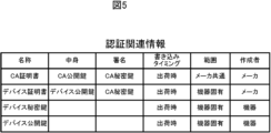
本実施の形態では、認証機器は、機器100の出荷時に機器100の記憶部12に書き込まれる認証関連情報に基づいて、被認証機器を認証する。図5に、認証関連情報を示す。認証関連情報は、CA(Certificate Authority)証明書とデバイス証明書とデバイス秘密鍵とデバイス公開鍵とを含む。CA証明書は、メーカ共通の証明書であり、デバイス証明書を検証するための証明書である。CA証明書は、メーカにより作成され、各機器100の工場出荷時に各機器100の記憶部12に書き込まれる。CA証明書には、CA公開鍵が含まれる。CA秘密鍵で暗号化した情報は、CA公開鍵で復号可能である。
デバイス証明書は、機器100固有の証明書であり、CA秘密鍵で署名されたデバイス公開鍵を含む証明書である。デバイス証明書は、メーカにより作成され、機器100の工場出荷時に機器100の記憶部12に書き込まれる。デバイス秘密鍵は、機器100固有の秘密鍵である。デバイス公開鍵は、機器100固有の公開鍵である。デバイス公開鍵で暗号化した情報は、デバイス秘密鍵で復号可能である。デバイス秘密鍵とデバイス公開鍵とは、機器100自身により作成され、機器100の工場出荷時に機器100の記憶部12に書き込まれる。
本実施の形態では、認証機器は、被認証機器から取得した被認証機器のデバイス証明書を、認証機器が保持するCA証明書で検証することにより、被認証機器を認証する。以下、図6を参照して、空気調和システム1000が実行する認証処理について説明する。なお、図6では、クラウドサーバ110とシステムコントローラ120と室外機131と室内機141と個別コントローラ151とに関するシーケンスが示され、他の機器に関するシーケンスが省略されている。
クラウドサーバ110とシステムコントローラ120と室外機131と室内機141と個別コントローラ151とのそれぞれは、機器認証のトリガが発生したことに応答して、機器認証を開始する。機器認証のトリガは、例えば、機器100毎に設定され、各ネットワークにおいて各機器100が完全に並行して機器認証を進めることが可能である。従って、機器認証が開始される順番は、図6に示す例に限定されない。例えば、図6において、システムコントローラ120による室外機131の機器認証は、室内機141による個別コントローラ151の機器認証の後に実行されてもよい。機器認証のトリガとしては、ユーザインタフェースに対するユーザ操作、プラグアンドプレイに基づくトリガ等が考えられる。ユーザ操作としては、タッチスクリーン、ディップスイッチ等を備える操作受付部14に対するユーザ操作が考えられる。
クラウドサーバ110は、上記トリガが発生した場合、ステップST111において、システムコントローラ120に、システムコントローラ120のデバイス証明書を要求する。一方、システムコントローラ120は、ステップST122において、システムコントローラ120のデバイス証明書をクラウドサーバ110に送信する。クラウドサーバ110は、ステップST113において、システムコントローラ120から受信したデバイス証明書を、クラウドサーバ110が保持するCA証明書で検証する。
具体的には、クラウドサーバ110は、デバイス証明書に含まれる、CA秘密鍵で署名されたデバイス公開鍵を、CA証明書に含まれるCA公開鍵で復号化する。クラウドサーバ110は、CA公開鍵によるデバイス公開鍵の復号化が成功した場合、デバイス証明書が正当な証明書であると判別し、システムコントローラ120が正当な機器100であると判別する。クラウドサーバ110は、CA公開鍵によるデバイス公開鍵の復号化が失敗した場合、デバイス証明書が不当な証明書であると判別し、システムコントローラ120が不当な機器100であると判別する。
また、システムコントローラ120は、上記トリガが発生した場合、ステップST121において、室外機131に、室外機131のデバイス証明書を要求する。一方、室外機131は、ステップST132において、室外機131のデバイス証明書をシステムコントローラ120に送信する。システムコントローラ120は、ステップST123において、室外機131から受信したデバイス証明書を、システムコントローラ120が保持するCA証明書で検証する。
システムコントローラ120、室外機131、室内機141等は、クラウドサーバ110と同様の手法により、デバイス証明書をCA証明書で検証する。また、図示を省略するが、システムコントローラ120は、室外機132に対してもデバイス証明書を要求し、室外機132から取得したデバイス証明書をCA証明書で検証する。
室外機131は、上記トリガが発生した場合、ステップST131において、室内機141に、室内機141のデバイス証明書を要求する。一方、室内機141は、ステップST142において、室内機141のデバイス証明書を室外機131に送信する。室外機131は、ステップST133において、室内機141から受信したデバイス証明書を、室外機131が保持するCA証明書で検証する。
なお、図示を省略するが、室外機131は、室内機142と個別コントローラ143とに対してもデバイス証明書を要求し、室内機142と個別コントローラ143とから取得したデバイス証明書をCA証明書で検証する。また、図示を省略するが、室外機132は、室内機144と室内機145と個別コントローラ146とに対してもデバイス証明書を要求し、室内機144と室内機145と個別コントローラ146とから取得したデバイス証明書をCA証明書で検証する。
室内機141は、上記トリガが発生した場合、ステップST141において、個別コントローラ151に、個別コントローラ151のデバイス証明書を要求する。一方、個別コントローラ151は、ステップST152において、個別コントローラ151のデバイス証明書を室内機141に送信する。室内機141は、ステップST143において、個別コントローラ151から受信したデバイス証明書を、室内機141が保持するCA証明書で検証する。なお、図示を省略するが、室内機145は、通信アダプタ152に対してデバイス証明書を要求し、通信アダプタ152から取得したデバイス証明書をCA証明書で検証する。
認証装置は、自機器による認証結果と子ノードから取得した認証結果とを、親ノードに送信する。具体的には、室内機141は、ステップST144において、個別コントローラ151に対する認証結果を室外機131に送信する。また、図示を省略するが、室内機145は、通信アダプタ152に対する認証結果を室外機132に送信する。また、室外機131は、ステップST134において、室内機141、室内機142、個別コントローラ143及び個別コントローラ151に対する認証結果をシステムコントローラ120に送信する。
また、図示を省略するが、室外機132は、室内機144、室内機145、個別コントローラ146及び通信アダプタ152に対する認証結果をシステムコントローラ120に送信する。また、システムコントローラ120は、ステップST124において、室外機131、室外機132、室内機141、室内機142、個別コントローラ143、室内機144、室内機145、個別コントローラ146、個別コントローラ151及び通信アダプタ152に対する認証結果をクラウドサーバ110に送信する。これにより、全ての認証結果が、ルートノードであるクラウドサーバ110に供給される。
以後、認証された機器100同士で暗号化通信が実行される。具体的には、まず、認証機器は、ネットワーク公開鍵とネットワーク秘密鍵とのペアを生成する。認証機器は、認証機器のデバイス秘密鍵で署名したネットワーク証明書と、ネットワーク秘密鍵とを、被認証機器のデバイス公開鍵で暗号化して、被認証機器に送信する。被認証機器は、暗号化されたネットワーク証明書とネットワーク秘密鍵とを、被認証機器のデバイス秘密鍵で復号化する。なお、ネットワーク証明書には、ネットワーク公開鍵が含まれている。以後、認証機器と被認証機器とは、ネットワーク証明書に基づいて、例えば、DTLS(Datagram Transport Layer Security)プロトコルに従って暗号化通信を実行する。
本実施の形態では、空気調和システム1000が備える複数のネットワーク200のそれぞれは、自機器が属するネットワーク200に属する他の機器を認証する認証機器を備える。つまり、本実施の形態では、ネットワーク200毎に認証機器が用意され、ネットワーク200毎に機器認証が実施される。このため、本実施の形態では、複数のネットワーク200における認証シーケンスが並行して実施可能である。
本実施の形態では、例えば、クラウドサーバ110、システムコントローラ120等の単一の機器100が他の全ての機器100を認証する形態に比べて、空気調和システム1000全体の機器認証に要する時間が短い。つまり、本実施の形態によれば、空気調和システム1000が備える機器100の認証に要する時間を短縮することができる。なお、各認証機器は、自機器が属さないネットワーク200に属する機器100を認証する必要がないため、それ程処理能力が高くなくてもよい。
また、本実施の形態では、第1ネットワークと第2ネットワークとに属し、第2ネットワークに属する他の機器を認証する第2認証機器は、第1ネットワークに属する第1認証機器により認証される。また、本実施の形態では、第2ネットワークと第3ネットワークとに属し、第3ネットワークに属する他の機器を認証する第3認証機器は、第2ネットワークに属する第2認証機器により認証される。つまり、本実施の形態では、第1認証機器以外の認証機器は、他の認証機器により認証される。従って、本実施の形態によれば、認証の基点である第1認証機器以外の全ての機器100の認証が可能である。
また、本実施の形態では、第1認証機器はクラウドサーバ110であり、第2認証機器はシステムコントローラ120である。クラウドサーバ110は、システムコントローラ120に比べて、偽装されにくく、信頼性が高い機器100である。このため、クラウドサーバ110は、他の機器から認証を受けなくても特段の問題が生じないと考えられる。また、システムコントローラ120は、クラウドサーバ110による認証を受ける。従って、本実施の形態によれば、セキュリティの向上が期待できる。
また、本実施の形態では、空気調和システム1000が備える複数の機器100は、ツリー構造で接続されており、複数のネットワーク200のそれぞれが備える認証機器は、自機器から見て子ノードに対応する機器100を認証する。本実施の形態では、ルートノードを基点として親ノードが子ノードを認証するという機器認証のチェーンが確立される。従って、本実施の形態によれば、ルートノード以外の全ての機器100が適切に認証される。
また、本実施の形態では、各ネットワーク200における認証シーケンスが独立しており、機器構成、ネットワーク構成等に依存しない認証シーケンスが採用可能である。例えば、本実施の形態では、機器認証の基点となる第1認証機器が、自機器が属する第1ネットワークに属する他の機器を認証する。なお、第1認証機器が複数の第1ネットワークに属する場合、第1認証機器は、各第1ネットワークに属する他の機器を認証する。第1認証機器から認証を受けた被認証機器は、第1認証機器が属さない第2ネットワークにも属する場合、第2認証機器として、第2ネットワークに属する他の機器を認証する。
第2認証機器から認証を受けた被認証機器は、第2認証機器が属さない第3ネットワークにも属する場合、第3認証機器として、第3ネットワークに属する他の機器を認証する。以下、同様の手順により、認証機器から認証を受けた被認証機器は、自機器が認証すべき他の機器が存在する場合、認証機器として、他の機器を認証する。かかる構成によれば、機器認証の基点となる第1認証機器以外の全ての機器100が認証される。
(実施の形態2)
実施の形態1では、偽装されにくく、信頼性が高いクラウドサーバ110を基点として機器認証が実施される例について説明した。本実施の形態では、このようなクラウドサーバ110が存在しない場合において、偽装されにくく、信頼性が高い冷媒系の機器100を基点として機器認証が実施される例について説明する。なお、実施の形態1と同様の構成及び機能については、適宜、説明を省略又は簡略化する。
実施の形態1では、偽装されにくく、信頼性が高いクラウドサーバ110を基点として機器認証が実施される例について説明した。本実施の形態では、このようなクラウドサーバ110が存在しない場合において、偽装されにくく、信頼性が高い冷媒系の機器100を基点として機器認証が実施される例について説明する。なお、実施の形態1と同様の構成及び機能については、適宜、説明を省略又は簡略化する。
図7は、本実施の形態に係る空気調和システム1200の構成を示す図である。空気調和システム1200は、システムコントローラ120と、室外機131と、室外機132と、室内機141と、室内機142と、個別コントローラ143と、室内機144と、室内機145と、個別コントローラ146と、個別コントローラ151と、通信アダプタ152とを備える。空気調和システム1200は、偽装されにくく、信頼性が高いクラウドサーバ110を備えていない。そこで、本実施の形態では、空気調和システム1200が備える機器100のうち、偽装されにくく、信頼性が高いと考えられる冷媒系の機器100を基点として、機器認証が実施される。
冷媒系の機器100としては、室外機131、室外機132、室内機141、室内機142、室内機144、室内機145等がある。ここで、一般的に、室外機と室内機とでは、サイズを考慮すると、室外機の方が偽物に置換しにくく、偽装されにくいと考えられる。つまり、室外機は、室内機よりも信頼性が高いと考えられる。また、一般的に、室外機は、室内機に比べて、処理能力が高いことが多い。そこで、本実施の形態では、機器認証の基点として、室外機が採用される。具体的には、本実施の形態では、機器認証の基点として、室外機131と室外機132とが採用される。
図8に示すように、本実施の形態では、空気調和システム1200が備える複数の機器100はツリー構造で接続されており、ルートノードは、システムコントローラ120である。
本実施の形態では、第1認証機器である室外機131は、第1ネットワークであるネットワーク220内において、システムコントローラ120を認証する。室外機131は、第1ネットワークであるネットワーク231内において、室内機141と室内機142と個別コントローラ143とを認証する。第1認証機器である室外機132は、第1ネットワークであるネットワーク220内において、システムコントローラ120を認証する。室外機132は、第1ネットワークであるネットワーク232内において、室内機144と室内機145と個別コントローラ146とを認証する。第2認証機器である室内機141は、第2ネットワークであるネットワーク241内において、個別コントローラ151を認証する。第2認証機器である室内機145は、第2ネットワークであるネットワーク242内において、通信アダプタ152を認証する。
本実施の形態においても、認証機器は、被認証機器から取得した被認証機器のデバイス証明書を、認証機器が保持するCA証明書で検証することにより、被認証機器を認証する。以下、図9を参照して、空気調和システム1200が実行する認証処理について説明する。なお、図9では、システムコントローラ120と室外機131と室内機141と個別コントローラ151とに関するシーケンスが示され、他の機器に関するシーケンスが省略されている。
まず、第1認証機器であり、機器認証の基点である室外機131は、機器認証のトリガが発生したことに応答して、機器認証を開始する。室外機131は、上記トリガが発生した場合、ステップST231Aにおいて、システムコントローラ120に、システムコントローラ120のデバイス証明書を要求する。一方、システムコントローラ120は、ステップST222において、システムコントローラ120のデバイス証明書を室外機131に送信する。室外機131は、ステップST233Aにおいて、システムコントローラ120から受信したデバイス証明書を、室外機131が保持するCA証明書で検証する。
また、室外機131は、ステップST231Bにおいて、室内機141に、室内機141のデバイス証明書を要求する。一方、室内機141は、ステップST242において、室内機141のデバイス証明書を室外機131に送信する。室外機131は、ステップST233Bにおいて、室内機141から受信したデバイス証明書を、室外機131が保持するCA証明書で検証する。なお、図示を省略するが、室外機131は、室内機142と個別コントローラ143とに対してもデバイス証明書を要求し、室内機142と個別コントローラ143とから取得したデバイス証明書をCA証明書で検証する。また、室外機131は、室外機132を認証してもよい。
また、室内機141は、上記トリガが発生した場合、ステップST241において、個別コントローラ151に、個別コントローラ151のデバイス証明書を要求する。一方、個別コントローラ151は、ステップST252において、個別コントローラ151のデバイス証明書を室内機141に送信する。室内機141は、ステップST243において、個別コントローラ151から受信したデバイス証明書を、室内機141が保持するCA証明書で検証する。
認証結果は、例えば、機器認証の基点の機器100である室外機131に供給される。つまり、室内機141は、ステップST244において、個別コントローラ151に対する認証結果を室外機131に送信する。これにより、室外機131は、室外機131を基点とした機器認証の全ての認証結果を取得することができる。なお、図示を省略するが、室外機132を基点とした機器認証の方法は、室外機131を基点とした機器認証の方法と同様である。室外機131を基点とした機器認証と室外機132を基点とした機器認証とが完了した後、認証された機器100同士で暗号化通信が実行される。
本実施の形態では、偽装されにくく、信頼性が高い冷媒系の機器100が、機器認証の基点である。従って、本実施の形態によれば、偽装されにくく、信頼性が高い冷媒系の機器100が、偽装されやすく、信頼性が低い機器100から不当な操作を受けることが抑制される。なお、本実施の形態では、偽装されにくく、信頼性が高い冷媒系の機器100のうち、室外機131と室外機132とが機器認証の基点である第1認証機器である。本実施の形態によれば、室内機141、室内機142、室内機144及び室内機145の偽装が検出可能である。
また、本実施の形態では、偽装されにくく、信頼性が高い冷媒系の機器100である第1認証機器、又は、第1認証機器から認証された第2認証機器が、偽装されやすく、信頼性が低いシステムコントローラ120を認証する。従って、本実施の形態によれば、冷媒系の機器100が、システムコントローラ120から不当な操作を受けることが抑制される。
(実施の形態3)
実施の形態2では、複数の冷媒系の機器100を基点として機器認証が実施される例について説明した。本実施の形態では、単一の冷媒系の機器100を基点として機器認証が実施される例について説明する。なお、実施の形態1,2と同様の構成及び機能については、適宜、説明を省略又は簡略化する。
実施の形態2では、複数の冷媒系の機器100を基点として機器認証が実施される例について説明した。本実施の形態では、単一の冷媒系の機器100を基点として機器認証が実施される例について説明する。なお、実施の形態1,2と同様の構成及び機能については、適宜、説明を省略又は簡略化する。
図10に示すように、本実施の形態に係る空気調和システム1300では、室外機131を機器認証の基点として、機器認証が実施される。具体的には、第1認証機器である室外機131は、第1ネットワークであるネットワーク220内において、システムコントローラ120と室外機132とを認証する。室外機131は、第1ネットワークであるネットワーク231内において、室内機141と室内機142と個別コントローラ143とを認証する。第2認証機器である室外機132は、第2ネットワークであるネットワーク232内において、室内機144と室内機145と個別コントローラ146とを認証する。第2認証機器である室内機141は、第2ネットワークであるネットワーク241内において、個別コントローラ151を認証する。第3認証機器である室内機145は、第3ネットワークであるネットワーク242内において、通信アダプタ152を認証する。
本実施の形態では、偽装されにくく、信頼性が高い冷媒系の機器100のうち、室外機131が機器認証の基点である第1認証機器である。本実施の形態によれば、室外機132、室内機141、室内機142、室内機144及び室内機145の偽装が検出可能である。
(実施の形態4)
実施の形態2では、室外機131と室外機132とを基点として機器認証が実施される例について説明した。本実施の形態では、室内機141と室内機144とを基点として機器認証が実施される例について説明する。なお、実施の形態1-3と同様の構成及び機能については、適宜、説明を省略又は簡略化する。
実施の形態2では、室外機131と室外機132とを基点として機器認証が実施される例について説明した。本実施の形態では、室内機141と室内機144とを基点として機器認証が実施される例について説明する。なお、実施の形態1-3と同様の構成及び機能については、適宜、説明を省略又は簡略化する。
図11に示すように、本実施の形態に係る空気調和システム1400では、室内機141と室内機144とを機器認証の基点として、機器認証が実施される。具体的には、第1認証機器である室内機141は、第1ネットワークであるネットワーク231内において、室外機131と室内機142と個別コントローラ143とを認証する。第1認証機器である室内機141は、第1ネットワークであるネットワーク241内において、個別コントローラ151を認証する。第2認証機器である室外機131は、第2ネットワークであるネットワーク220内において、システムコントローラ120を認証する。
第1認証機器である室内機144は、第1ネットワークであるネットワーク232内において、室外機132と室内機145と個別コントローラ146とを認証する。第2認証機器である室外機132は、第2ネットワークであるネットワーク220内において、システムコントローラ120を認証する。第2認証機器である室内機145は、第2ネットワークであるネットワーク242内において、通信アダプタ152を認証する。
本実施の形態では、偽装されにくく、信頼性が高い冷媒系の機器100のうち、室内機141と室内機144とが機器認証の基点である第1認証機器である。本実施の形態によれば、室外機131、室外機132、室内機142及び室内機145の偽装が検出可能である。
(実施の形態5)
実施の形態4では、室内機141と室内機144とを基点として機器認証が実施される例について説明した。本実施の形態では、室内機141を基点として機器認証が実施される例について説明する。なお、実施の形態1-4と同様の構成及び機能については、適宜、説明を省略又は簡略化する。
実施の形態4では、室内機141と室内機144とを基点として機器認証が実施される例について説明した。本実施の形態では、室内機141を基点として機器認証が実施される例について説明する。なお、実施の形態1-4と同様の構成及び機能については、適宜、説明を省略又は簡略化する。
図12に示すように、本実施の形態に係る空気調和システム1500では、室内機141を機器認証の基点として、機器認証が実施される。具体的には、第1認証機器である室内機141は、第1ネットワークであるネットワーク231内において、室外機131と室内機142と個別コントローラ143とを認証する。第1認証機器である室内機141は、第1ネットワークであるネットワーク241内において、個別コントローラ151を認証する。第2認証機器である室外機131は、第2ネットワークであるネットワーク220内において、システムコントローラ120と室外機132とを認証する。
第3認証機器である室外機132は、第3ネットワークであるネットワーク232内において、室内機144と室内機145と個別コントローラ146とを認証する。第4認証機器である室内機145は、第4ネットワークであるネットワーク242内において、通信アダプタ152を認証する。
本実施の形態では、偽装されにくく、信頼性が高い冷媒系の機器100のうち、室内機141が機器認証の基点である。本実施の形態によれば、室外機131、室外機132、室内機142、室内機144及び室内機145の偽装が検出可能である。
(実施の形態6)
実施の形態1では、機器認証において単方向認証が実施される例について説明した。本実施の形態では、機器認証において双方向認証である相互認証が実施される例について説明する。なお、実施の形態1-5と同様の構成及び機能については、適宜、説明を省略又は簡略化する。
実施の形態1では、機器認証において単方向認証が実施される例について説明した。本実施の形態では、機器認証において双方向認証である相互認証が実施される例について説明する。なお、実施の形態1-5と同様の構成及び機能については、適宜、説明を省略又は簡略化する。
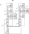
図13に示すように、本実施の形態では、空気調和システム1600が備える複数の機器100は、システムコントローラ120をルートノードとするツリー構造で接続されている。
本実施の形態では、親ノードが子ノードを認証し、子ノードが親ノードを認証する。つまり、システムコントローラ120は、ネットワーク220内において、室外機131と室外機132とを認証する。また、室外機131と室外機132とは、ネットワーク220内において、システムコントローラ120を認証する。
室外機131は、ネットワーク231内において、室内機141と室内機142と個別コントローラ143とを認証する。室内機141と室内機142と個別コントローラ143とは、ネットワーク231内において、室外機131を認証する。室外機132は、ネットワーク232内において、室内機144と室内機145と個別コントローラ146とを認証する。室内機144と室内機145と個別コントローラ146とは、ネットワーク232内において、室外機132を認証する。
室内機141は、ネットワーク241内において、個別コントローラ151を認証する。個別コントローラ151は、ネットワーク241内において、室内機141を認証する。室内機145は、ネットワーク242内において、通信アダプタ152を認証する。通信アダプタ152は、ネットワーク242内において、室内機145を認証する。
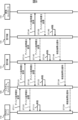
以下、図14を参照して、空気調和システム1600が実行する認証処理について説明する。なお、図14では、システムコントローラ120と室外機131と室内機141と個別コントローラ151とに関するシーケンスが示され、他の機器に関するシーケンスが省略されている。
まず、システムコントローラ120は、ステップST321において、室外機131に、室外機131のデバイス証明書を要求する。一方、室外機131は、ステップST332Aにおいて、室外機131のデバイス証明書をシステムコントローラ120に送信する。システムコントローラ120は、ステップST323において、室外機131から受信したデバイス証明書を、システムコントローラ120が保持するCA証明書で検証する。
また、室外機131は、ステップST331Bにおいて、システムコントローラ120に、システムコントローラ120のデバイス証明書を要求する。一方、システムコントローラ120は、ステップST322Bにおいて、システムコントローラ120のデバイス証明書を室外機131に送信する。室外機131は、ステップST333Bにおいて、システムコントローラ120から受信したデバイス証明書を、室外機131が保持するCA証明書で検証する。また、図示を省略するが、システムコントローラ120と室外機132とは、互いに認証し合う。
また、室外機131は、ステップST331Aにおいて、室内機141に、室内機141のデバイス証明書を要求する。一方、室内機141は、ステップST342Aにおいて、室内機141のデバイス証明書を室外機131に送信する。室外機131は、ステップST333Aにおいて、室内機141から受信したデバイス証明書を、室外機131が保持するCA証明書で検証する。
また、室内機141は、ステップST341Bにおいて、室外機131に、室外機131のデバイス証明書を要求する。一方、室外機131は、ステップST332Bにおいて、室外機131のデバイス証明書を室内機141に送信する。室内機141は、ステップST343Bにおいて、室外機131から受信したデバイス証明書を、室内機141が保持するCA証明書で検証する。また、図示を省略するが、室外機131と室内機142との間、室外機131と個別コントローラ143との間、室外機132と室内機144との間、室外機132と室内機145との間、室外機132と個別コントローラ146との間においても、互いに認証が実施される。
また、室内機141は、ステップST341Aにおいて、個別コントローラ151に、個別コントローラ151のデバイス証明書を要求する。一方、個別コントローラ151は、ステップST352において、個別コントローラ151のデバイス証明書を室内機141に送信する。室内機141は、ステップST343Aにおいて、個別コントローラ151から受信したデバイス証明書を、室内機141が保持するCA証明書で検証する。
また、個別コントローラ151は、ステップST351において、室内機141に、室内機141のデバイス証明書を要求する。一方、室内機141は、ステップST342Bにおいて、室内機141のデバイス証明書を個別コントローラ151に送信する。個別コントローラ151は、ステップST353において、室内機141から受信したデバイス証明書を、個別コントローラ151が保持するCA証明書で検証する。また、図示を省略するが、室内機145と通信アダプタ152とは、互いに認証し合う。
認証結果は、例えば、ルートノードであるシステムコントローラ120に供給される。具体的には、個別コントローラ151は、ステップST354において、室内機141に対する認証結果を室内機141に送信する。また、図示を省略するが、通信アダプタ152は、室内機145に対する認証結果を室内機145に送信する。また、室内機141は、ステップST344において、室内機141及び個別コントローラ151に対する認証結果を室外機131に送信する。また、図示を省略するが、室内機145は、室内機145及び通信アダプタ152に対する認証結果を室外機132に送信する。
また、室外機131は、ステップST334において、室外機131、室内機141、室内機142、個別コントローラ143及び個別コントローラ151に対する認証結果をシステムコントローラ120に送信する。また、図示を省略するが、室外機132は、室外機132、室内機144、室内機145、個別コントローラ146及び通信アダプタ152に対する認証結果をシステムコントローラ120に送信する。これにより、全ての認証結果が、ルートノードであるシステムコントローラ120に供給される。以後、認証された機器100同士で暗号化通信が実行される。
本実施の形態では、複数のネットワーク200のそれぞれにおいて、認証機器と被認証機器との間で相互に認証が実施される。本実施の形態によれば、偽装されにくく、信頼性が高いクラウドサーバ110が存在しない場合においても、システムコントローラ120と冷媒系の機器100とを含む全ての機器100の認証が可能である。
(変形例)
以上、本開示の実施の形態を説明したが、本開示を実施するにあたっては、種々の形態による変形及び応用が可能である。本開示において、上記実施の形態において説明した構成、機能、動作のどの部分を採用するのかは任意である。また、本開示において、上述した構成、機能、動作のほか、更なる構成、機能、動作が採用されてもよい。また、上記実施の形態において説明した構成、機能、動作は、自由に組み合わせることができる。
以上、本開示の実施の形態を説明したが、本開示を実施するにあたっては、種々の形態による変形及び応用が可能である。本開示において、上記実施の形態において説明した構成、機能、動作のどの部分を採用するのかは任意である。また、本開示において、上述した構成、機能、動作のほか、更なる構成、機能、動作が採用されてもよい。また、上記実施の形態において説明した構成、機能、動作は、自由に組み合わせることができる。
各ネットワーク200の認証機器が被認証機器の認証を開始するトリガは、適宜、調整することができる。例えば、各ネットワーク200の認証機器は、空気調和システム1000が備える複数の機器100のうち特定の機器100からの要求に従って、被認証機器の認証を開始してもよい。又は、各ネットワーク200の認証機器は、自発的に被認証機器の認証を開始してもよい。このように、機器認証の方向と機器認証の実行順序とは、一致しなくてもよい。
空気調和システムの構成は、実施の形態1-6で示したものに限定されない。例えば、実施の形態1において、ネットワーク220において、室外機131の代わりに室内機141がシステムコントローラ120に接続され、ネットワーク231において、室内機141と室外機131とが接続されてもよい。この場合、ネットワーク220において、室内機141はシステムコントローラ120から認証を受け、ネットワーク231において、室外機131は室内機141から認証を受けることが好適である。
機器認証の基点となる第1認証機器は、実施の形態1-6で示した機器100に限定されない。例えば、室外機132又は室内機144が単独で第1認証機器に設定されてもよいし、システムコントローラ120、室内機142、個別コントローラ143、室内機145、個別コントローラ146、個別コントローラ151、通信アダプタ152のうち少なくとも1つの機器100が第1認証機器に設定されてもよい。
各ネットワーク200には複数の認証機器が設けられてもよいが、各ネットワーク200には1つの認証機器が設けられることが望ましい。各ネットワーク200における1つの認証機器を決定する方法は、適宜、調整することができる。認証機器は、各ネットワーク200において、必ず存在して一意に決定される機器100であることが好適である。例えば、各ネットワーク200において、ネットワークアドレスが最小の機器100、ネットワーク200内の他の機器に給電している機器100等が、認証機器に決定されてもよい。
本開示は、本開示の広義の精神と範囲を逸脱することなく、様々な実施の形態及び変形が可能とされるものである。また、上述した実施の形態は、この開示を説明するためのものであり、本開示の範囲を限定するものではない。すなわち、本開示の範囲は、実施の形態ではなく、請求の範囲によって示される。そして請求の範囲内及びそれと同等の開示の意義の範囲内で施される様々な変形が、この開示の範囲内とみなされる。
本開示は、室外機と室内機とを含む複数の機器を備える空気調和システムに適用可能である。
11 制御部、12 記憶部、13 表示部、14 操作受付部、15 第1通信部、16 第2通信部、100,100A,100B,100C,100D,100E,100F,100G 機器、110 クラウドサーバ、120 システムコントローラ、131,132 室外機、141,142,144,145 室内機、143,146,151 個別コントローラ、152 通信アダプタ、200,200A,200B,200C,210,220,231,232,241,242 ネットワーク、300,300A,300B,300C,311,312,320,331,332,341,342 通信回線、500 ブロードバンドルータ、1000,1200,1300,1400,1500,1600 空気調和システム
Claims (9)
- 室外機と室内機とを含む複数の機器を備える空気調和システムであって、
前記複数の機器のそれぞれは、複数のネットワークのうち少なくとも1つのネットワークに属し、
前記複数のネットワークのそれぞれは、自機器が属するネットワークに属する他の機器を認証する認証機器を備える、
空気調和システム。 - 前記複数のネットワークは、第1ネットワークと第2ネットワークとを含み、
前記複数の機器は、前記第1ネットワークに属し、前記第1ネットワークに属する他の機器を認証する第1認証機器と、前記第1ネットワークと前記第2ネットワークとに属し、前記第1認証機器により認証され、前記第2ネットワークに属する他の機器を認証する第2認証機器とを含む、
請求項1に記載の空気調和システム。 - 前記複数のネットワークは、前記第1ネットワークと前記第2ネットワークと第3ネットワークとを含み、
前記複数の機器は、前記第1認証機器と、前記第2認証機器と、前記第2ネットワークと前記第3ネットワークとに属し、前記第2認証機器により認証され、前記第3ネットワークに属する他の機器を認証する第3認証機器とを含む、
請求項2に記載の空気調和システム。 - 前記複数の機器は、前記室外機と前記室内機とを制御するシステムコントローラと、前記システムコントローラと接続されるクラウドサーバとを含み、
前記第1認証機器は、前記クラウドサーバであり、
前記第2認証機器は、前記システムコントローラである、
請求項2又は3に記載の空気調和システム。 - 前記第1認証機器は、前記室外機と前記室内機とのうち一方の機器である、
請求項2又は3に記載の空気調和システム。 - 前記複数の機器は、前記室外機と前記室内機とを制御するシステムコントローラを含み、
前記第1認証機器又は前記第2認証機器は、前記システムコントローラを認証する、
請求項5に記載の空気調和システム。 - 前記複数の機器は、ツリー構造で接続されており、
前記複数のネットワークのそれぞれが備える前記認証機器は、自機器から見て子ノードに対応する機器を認証する、
請求項1から4の何れか1項に記載の空気調和システム。 - 前記複数のネットワークのそれぞれにおいて、前記認証機器と前記認証機器から認証される前記他の機器との間で相互に認証が実施される、
請求項1から7の何れか1項に記載の空気調和システム。 - 室外機と室内機とを含む複数の機器を備える空気調和システムが実行する認証方法であって、
前記複数の機器のそれぞれは、複数のネットワークのうち少なくとも1つのネットワークに属し、
前記複数のネットワークのそれぞれが備える認証機器が、自機器が属するネットワークに属する他の機器を認証する、
認証方法。
Priority Applications (2)
| Application Number | Priority Date | Filing Date | Title |
|---|---|---|---|
| JP2025525431A JP7778274B2 (ja) | 2023-06-05 | 2023-06-05 | 空気調和システム、及び、認証方法 |
| PCT/JP2023/020781 WO2024252454A1 (ja) | 2023-06-05 | 2023-06-05 | 空気調和システム、及び、認証方法 |
Applications Claiming Priority (1)
| Application Number | Priority Date | Filing Date | Title |
|---|---|---|---|
| PCT/JP2023/020781 WO2024252454A1 (ja) | 2023-06-05 | 2023-06-05 | 空気調和システム、及び、認証方法 |
Publications (1)
| Publication Number | Publication Date |
|---|---|
| WO2024252454A1 true WO2024252454A1 (ja) | 2024-12-12 |
Family
ID=93795237
Family Applications (1)
| Application Number | Title | Priority Date | Filing Date |
|---|---|---|---|
| PCT/JP2023/020781 Ceased WO2024252454A1 (ja) | 2023-06-05 | 2023-06-05 | 空気調和システム、及び、認証方法 |
Country Status (2)
| Country | Link |
|---|---|
| JP (1) | JP7778274B2 (ja) |
| WO (1) | WO2024252454A1 (ja) |
Citations (7)
| Publication number | Priority date | Publication date | Assignee | Title |
|---|---|---|---|---|
| JP2004197993A (ja) * | 2002-12-17 | 2004-07-15 | Daikin Ind Ltd | 空調室外機及び空調室外機ネットワーク形成方法 |
| JP2004200857A (ja) * | 2002-12-17 | 2004-07-15 | Daikin Ind Ltd | 設備機器管理システム、パケットの優先制御方法、ネットワーク管理装置、空調室内機、通信サービス提供方法及び通信サービス提供システム |
| JP2016044884A (ja) * | 2014-08-22 | 2016-04-04 | 三菱重工業株式会社 | アドレス設定装置、空調システム、及びアドレス設定方法 |
| JP2016044885A (ja) * | 2014-08-22 | 2016-04-04 | 三菱重工業株式会社 | 機器認証装置、空調システム、及び機器認証方法 |
| JP2016051185A (ja) * | 2014-08-28 | 2016-04-11 | 三菱重工業株式会社 | 制御プログラム配信システム及びその方法 |
| CN112161312A (zh) * | 2020-09-23 | 2021-01-01 | 青岛海信日立空调系统有限公司 | 一种多联机空调地暖集控系统 |
| WO2021166105A1 (ja) * | 2020-02-19 | 2021-08-26 | 三菱電機株式会社 | 冷凍サイクル装置および冷凍システム |
Family Cites Families (5)
| Publication number | Priority date | Publication date | Assignee | Title |
|---|---|---|---|---|
| KR101513613B1 (ko) * | 2008-01-21 | 2015-04-20 | 엘지전자 주식회사 | 멀티에어컨 시스템의 중앙 제어 장치 및 그의 제어 방법 |
| JP6710330B2 (ja) | 2017-05-30 | 2020-06-17 | 三菱電機株式会社 | 通信制御システム及び通信制御方法 |
| KR102844106B1 (ko) * | 2020-07-24 | 2025-08-07 | 엘지전자 주식회사 | 공기조화기 및 그 제어방법 |
| CN113865023B (zh) | 2021-09-26 | 2023-05-30 | 青岛海信日立空调系统有限公司 | 一种多联机空调系统 |
| WO2023148942A1 (ja) | 2022-02-04 | 2023-08-10 | 三菱電機株式会社 | ネットワークシステム、及び、ネットワーク認識方法 |
-
2023
- 2023-06-05 WO PCT/JP2023/020781 patent/WO2024252454A1/ja not_active Ceased
- 2023-06-05 JP JP2025525431A patent/JP7778274B2/ja active Active
Patent Citations (7)
| Publication number | Priority date | Publication date | Assignee | Title |
|---|---|---|---|---|
| JP2004197993A (ja) * | 2002-12-17 | 2004-07-15 | Daikin Ind Ltd | 空調室外機及び空調室外機ネットワーク形成方法 |
| JP2004200857A (ja) * | 2002-12-17 | 2004-07-15 | Daikin Ind Ltd | 設備機器管理システム、パケットの優先制御方法、ネットワーク管理装置、空調室内機、通信サービス提供方法及び通信サービス提供システム |
| JP2016044884A (ja) * | 2014-08-22 | 2016-04-04 | 三菱重工業株式会社 | アドレス設定装置、空調システム、及びアドレス設定方法 |
| JP2016044885A (ja) * | 2014-08-22 | 2016-04-04 | 三菱重工業株式会社 | 機器認証装置、空調システム、及び機器認証方法 |
| JP2016051185A (ja) * | 2014-08-28 | 2016-04-11 | 三菱重工業株式会社 | 制御プログラム配信システム及びその方法 |
| WO2021166105A1 (ja) * | 2020-02-19 | 2021-08-26 | 三菱電機株式会社 | 冷凍サイクル装置および冷凍システム |
| CN112161312A (zh) * | 2020-09-23 | 2021-01-01 | 青岛海信日立空调系统有限公司 | 一种多联机空调地暖集控系统 |
Also Published As
| Publication number | Publication date |
|---|---|
| JPWO2024252454A1 (ja) | 2024-12-12 |
| JP7778274B2 (ja) | 2025-12-01 |
Similar Documents
| Publication | Publication Date | Title |
|---|---|---|
| US10027643B2 (en) | Authenticating home device using device token issued based on identifier of terminal | |
| CN102246455A (zh) | 自我认证通信设备以及设备认证系统 | |
| US12413584B2 (en) | Method and system for self-onboarding of IoT devices | |
| WO2023109240A1 (zh) | 智能门锁的绑定方法和装置、存储介质及电子装置 | |
| JP6358529B2 (ja) | 通信機器 | |
| US20240179145A1 (en) | Method for connection establishment and internet of things (iot) device | |
| JP6490191B2 (ja) | サーバ、証明書生成指示方法、及び、プログラム | |
| JP7778274B2 (ja) | 空気調和システム、及び、認証方法 | |
| CN105828330B (zh) | 一种接入方法及装置 | |
| JP7289111B2 (ja) | 通信装置、認証方法およびコンピュータプログラム | |
| JP2021002798A (ja) | 設備装置、空気調和機、照明装置、空気調和機コントローラ、携帯装置、及び通信システム | |
| JP2005122695A (ja) | 認証方法、サーバ計算機、クライアント計算機、および、プログラム | |
| US8195936B2 (en) | Method for transmitting and receiving data of a terminal in a communication system and communication terminal thereof | |
| CN116800522B (zh) | 智能家电IPv6接入认证和授权控制系统的处理方法 | |
| JP6653484B2 (ja) | 認証装置、認証システム及び認証方法 | |
| TW202017345A (zh) | 用於網狀網路的連線建立系統及方法 | |
| JP6281749B2 (ja) | 通信システム及び機器 | |
| JP2008252353A (ja) | 遠隔監視システム並びにセンタ装置 | |
| CN111698096B (zh) | 基于ndn的智能家居设备自动化安全登录方法 | |
| JP6013213B2 (ja) | 通信装置、通信システム、プログラム | |
| JP2022084548A (ja) | 遠い位置に置かれたコンポーネントに関連付けられている証明書を管理するシステム及び方法 | |
| CN115514610B (zh) | 一种基于mqtt的物联网构建多联机的方法 | |
| US11882119B2 (en) | Communication system, cryptographic key distribution method, management communication apparatus, and communication apparatus | |
| JP7170212B2 (ja) | 通信装置、通信方法およびコンピュータプログラム | |
| AU2024285961A1 (en) | Method for constructing a decentralised data communication structure within a system having a plurality of components |
Legal Events
| Date | Code | Title | Description |
|---|---|---|---|
| 121 | Ep: the epo has been informed by wipo that ep was designated in this application |
Ref document number: 23940562 Country of ref document: EP Kind code of ref document: A1 |
|
| WWE | Wipo information: entry into national phase |
Ref document number: 2025525431 Country of ref document: JP |
|
| NENP | Non-entry into the national phase |
Ref country code: DE |