WO2024252455A1 - 電力伝送デバイスおよびモータ装置 - Google Patents
電力伝送デバイスおよびモータ装置 Download PDFInfo
- Publication number
- WO2024252455A1 WO2024252455A1 PCT/JP2023/020786 JP2023020786W WO2024252455A1 WO 2024252455 A1 WO2024252455 A1 WO 2024252455A1 JP 2023020786 W JP2023020786 W JP 2023020786W WO 2024252455 A1 WO2024252455 A1 WO 2024252455A1
- Authority
- WO
- WIPO (PCT)
- Prior art keywords
- shaft
- winding
- motor
- rotating member
- circumferential direction
- Prior art date
- Legal status (The legal status is an assumption and is not a legal conclusion. Google has not performed a legal analysis and makes no representation as to the accuracy of the status listed.)
- Ceased
Links
Images


Classifications
-
- H—ELECTRICITY
- H01—ELECTRIC ELEMENTS
- H01F—MAGNETS; INDUCTANCES; TRANSFORMERS; SELECTION OF MATERIALS FOR THEIR MAGNETIC PROPERTIES
- H01F38/00—Adaptations of transformers or inductances for specific applications or functions
- H01F38/18—Rotary transformers
-
- H—ELECTRICITY
- H01—ELECTRIC ELEMENTS
- H01F—MAGNETS; INDUCTANCES; TRANSFORMERS; SELECTION OF MATERIALS FOR THEIR MAGNETIC PROPERTIES
- H01F38/00—Adaptations of transformers or inductances for specific applications or functions
- H01F38/14—Inductive couplings
Definitions
- the present invention relates to a power transmission device that transmits power contactlessly, and a motor device equipped with such a power transmission device.
- one type of motor is the electrically excited synchronous motor (EESM).
- EESM electrically excited synchronous motor
- This motor has a stator with windings wound around it, and a rotor with windings wound around it.
- the efficiency of the motor can be improved by changing the current flowing through the windings wound around the rotor according to the rotational speed of the motor.
- Patent Document 1 discloses a rotary transformer that has a stator wound with a winding and a rotor wound with a winding, and is capable of transmitting power between the stator and the rotor.
- high reliability is desirable for electronic devices, and high reliability is also expected for power transmission devices capable of transmitting power from a stator to a rotor.
- the power transmission device includes a magnetic core, a first winding, a first rotating member, a second winding, and one or more rectifying elements.
- the magnetic core has a ring shape including a through hole through which the shaft passes, includes a cavity inside along the circumferential direction of the rotating axis of the shaft, and has an opening provided along the circumferential direction on a surface in contact with the through hole, connecting the through hole and the cavity.
- the first winding is provided in the cavity and wound along the circumferential direction.
- the first rotating member is provided at a position corresponding to the opening in the axial direction of the rotating shaft, and is capable of rotating circumferentially inside the cavity in response to rotation of the shaft.
- the second winding is provided on the first rotating member and wound along the circumferential direction.
- the one or more rectifying elements are provided so as to be in contact with the shaft, and are connected to the second winding.
- a motor device includes a motor, a shaft, an inverter, a magnetic core, a first winding, a rotating member, a second winding, and one or more rectifying elements.
- the motor includes a motor stator including a first motor magnetic core and a first motor winding, and a motor rotor including a second motor magnetic core and a second motor winding.
- the shaft is connected to the motor rotor.
- the magnetic core has a ring shape including a through hole through which the shaft passes, includes a cavity along the circumferential direction of the shaft, and has an opening provided along the circumferential direction on a surface in contact with the through hole and connecting the through hole and the cavity.
- the first winding is connected to the inverter, provided in the cavity, and wound along the circumferential direction.
- the first rotating member is provided at a position corresponding to the opening in the axial direction of the shaft, and is rotatable circumferentially inside the cavity in response to rotation of the shaft.
- the second winding is provided on the first rotating member and wound along the circumferential direction.
- One or more rectifying elements are provided in contact with the shaft, connected to the second winding, and provided in a path connecting the second winding and the second motor winding.
- the power transmission device and motor device according to one embodiment of the present invention can improve reliability.
- FIG. 1 is a block diagram showing an example of the configuration of a motor device according to a first embodiment of the present invention.
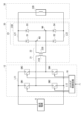
- FIG. 2 is a circuit diagram illustrating an example of a configuration of an inverter and a power transmission device according to an embodiment.
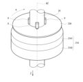
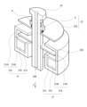
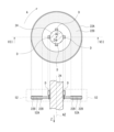
- FIG. 3 is a perspective view illustrating a configuration example of the power transmission device illustrated in FIG. 1 .
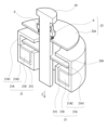
- FIG. 4 is an explanatory diagram illustrating a configuration example of the power transmission device illustrated in FIG. 3.
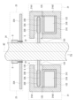
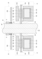
- FIG. 5 is a cross-sectional view illustrating an example of a configuration of the power transmission device illustrated in FIG. 3 .
- FIG. 6 is an explanatory diagram showing an example of the configuration of the stator shown in FIG. FIG.
- FIG. 7 is an explanatory diagram showing an example of the configuration of the rotor and the flow straightening member shown in FIG.
- FIG. 8 is an explanatory diagram illustrating an operation example of the power transmission device illustrated in FIG.
- FIG. 9 is a cross-sectional view illustrating a configuration example of a power transfer device according to a modified example of the first embodiment.
- FIG. 10 is a cross-sectional view illustrating a configuration example of a power transfer device according to another modified example of the first embodiment.
- FIG. 11 is a cross-sectional view showing an example of the configuration of the rotor and the straightening member shown in FIG.
- FIG. 12 is a cross-sectional view illustrating a configuration example of a rotor and a straightening member according to another modified example of the first embodiment.
- FIG. 13 is a diagram illustrating a configuration example of a power transfer device according to another modified example of the first embodiment.
- FIG. 14 is a cross-sectional view illustrating a configuration example of a power transfer device according to another modified example of the first embodiment.
- FIG. 15 is a block diagram showing an example of the configuration of a motor device according to the second embodiment.
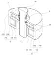
- FIG. 16 is a perspective view illustrating a configuration example of the power transmission device illustrated in FIG. 15.
- FIG. 17 is an explanatory diagram illustrating a configuration example of the power transmission device illustrated in FIG. 16.
- FIG. 18 is a cross-sectional view illustrating a configuration example of the power transmission device illustrated in FIG. FIG.
- FIG. 19 is an explanatory diagram illustrating a configuration example of the rotor shown in FIG.
- FIG. 20 is a cross-sectional view illustrating a configuration example of a power transfer device according to a modified example of the second embodiment.
- FIG. 21 is a cross-sectional view illustrating a configuration example of a power transfer device according to another modification of the second embodiment.
- FIG. 22 is a cross-sectional view showing one configuration example of the rotor and the flow straightening member shown in FIG. 21. As shown in FIG.
- First Embodiment [Configuration example] 1 shows an example of a configuration of a motor device 1 including a power transmission device according to a first embodiment of the present invention.
- the motor device 1 is connected to an external control device 8 and a DC power source 9.
- the external control device 8 is configured to instruct the motor device 1 on a rotation speed.
- the DC power source 9 is configured to supply DC power to the motor device 1.
- the motor device 1 is configured to generate a driving force, which is mechanical energy, based on an instruction from the external control device 8, using the DC power supplied from the DC power source 9.
- the motor device 1 includes a drive unit 10 and a motor 30.
- the drive unit 10 is configured to drive the motor 30.
- the drive unit 10 has inverters 11 and 12, a power transmission device 20, and a control circuit 19.
- the inverter 11 is configured to convert the DC power supplied from the DC power source 9 into three-phase (U-phase, V-phase, W-phase) AC power based on instructions from the control circuit 19. The inverter 11 then supplies this three-phase AC power to the windings 31B (described below) of the stator 31 of the motor 30.
- the inverter 12 is configured to convert the DC power supplied from the DC power source 9 into single-phase AC power based on instructions from the control circuit 19. The inverter 12 then supplies this AC power to a winding 21B (described below) of a stator 21 of the power transmission device 20.
- the power transmission device 20 has a stator 21, a rotor 22, a rectifying member 23, and a shaft 24.
- the power transmission device 20 is configured to transmit AC power supplied from the inverter 12 from the stator 21 to the rotor 22 by non-contact transmission.
- FIG. 2 shows an example of the configuration of the inverter 12 and the power transmission device 20. Note that FIG. 2 also shows the DC power supply 9 and the winding 32B of the rotor 32 of the motor 30.
- the inverter 12 is connected to the DC power supply 9 via the voltage line L11 and the reference voltage line L12.
- the inverter 12 is a full-bridge type circuit.
- the inverter 12 has switching elements SW1 to SW4 and a switching control circuit 18.
- Each of the switching elements SW1 to SW4 is configured using, for example, a field effect transistor or an insulated gate bipolar transistor.
- the switching element SW1 is provided on a path connecting the voltage line L11 and the node N1, and is configured to perform a switching operation based on a control signal supplied from the switching control circuit 18.
- the switching element SW2 is provided on a path connecting the node N1 and the reference voltage line L12, and is configured to perform a switching operation based on a control signal supplied from the switching control circuit 18.
- the switching element SW3 is provided on a path connecting the voltage line L11 and the node N2, and is configured to perform a switching operation based on a control signal supplied from the switching control circuit 18.
- the switching element SW4 is provided on a path connecting the node N2 and the reference voltage line L12, and is configured to perform a switching operation based on a control signal supplied from the switching control circuit 18.
- the switching control circuit 18 is configured to control the switching operation of the switching elements SW1 to SW4 by supplying control signals to the switching elements SW1 to SW4, respectively, based on instructions from the control circuit 19.
- the power transmission device 20 has a winding 21B, a winding 22B, and a rectifier circuit 23B.
- the winding 21B is provided on the stator 21, one end of the winding 21B is connected to a node N1 of the inverter 12, and the other end of the winding 21B is connected to a node N2 of the inverter 12.
- the winding 22B is provided on the rotor 22, one end of the winding 22B is connected to a node N3 of the rectifier circuit 23B, and the other end is connected to a node N4 of the rectifier circuit 23B.
- the windings 21B and 22B form a so-called rotary transformer, and the winding 22B is adapted to receive AC power supplied from the winding 21B.
- the rectifier circuit 23B is provided on the rectifier member 23, and is configured to rectify the AC power supplied from the winding 22B of the rotor 22.
- the rectifier circuit 23B has diodes D1 to D4.
- the diodes D1 to D4 are rectifier elements.
- the cathode of diode D1 is connected to voltage line L21, and the anode is connected to node N3.
- the cathode of diode D2 is connected to node N3, and the anode is connected to reference voltage line L22.
- the cathode of diode D3 is connected to voltage line L21, and the anode is connected to node N4.
- the cathode of diode D4 is connected to node N4, and the anode is connected to reference voltage line L22.
- Voltage line L21 and reference voltage line L22 are connected to winding 32B (described below) of rotor 32 of motor 30.
- the inverter 12 converts the DC power supplied from the DC power source 9 into AC power.
- the power transmission device 20 transmits the AC power supplied from the inverter 12 from the stator 21 of the power transmission device 20 to the rotor 22 of the power transmission device 20, and rectifies the transmitted AC power.
- the power transmission device 20 supplies the rectified power to the winding 32B (described later) of the rotor 32 of the motor 30.
- the power rectified by the rectifier circuit 23B is directly supplied to the winding 32B, but this is not limited to this. Instead, for example, the power rectified by the rectifier circuit 23B may be supplied to the winding 32B via a stabilization circuit including a capacitor.
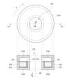
- Figures 3 and 4 show an example of the configuration of the power transmission device 20.
- Figure 5 shows an example of the cross-sectional structure of the power transmission device 20 in a plane including the rotation axis AZ.
- Figure 6 shows an example of the configuration of the stator 21.
- Figure 6 also shows the cross-sectional structure of the stator 21 in a plane including the rotation axis AZ in the direction of the VI-VI arrows.
- Figure 7 shows an example of the configuration of the rotor 22 and the straightening member 23.
- Figure 7 also shows the cross-sectional structure of the rotor 22 and the straightening member 23 in a plane including the rotation axis AZ in the direction of the VII-VII arrows.
- the stator 21 is a so-called stator, and is fixed to a housing (not shown) of the motor device 1. As shown in Figures 3 to 6, the stator 21 has a magnetic core 21A and windings 21B.
- the magnetic core 21A is made of a magnetic material such as ferrite.
- the magnetic core 21A includes magnetic cores 21A1 and 21A2.
- the magnetic cores 21A1 and 21A2 are arranged to sandwich the rotor 22 in the Z direction.
- the Z direction is the extension direction of the rotation axis AZ, and is the direction from the motor 30 to the power transmission device 20 as shown in FIG. 1.
- Each of the magnetic cores 21A1 and 21A2 is a ring-shaped magnetic member having a through hole 120 (FIGS. 5 and 6) through which the shaft 24 passes.
- the outer part of the magnetic core 21A1 in the radial direction (horizontal direction in FIG. 5) is bent in the Z direction and is connected to the magnetic core 21A2 at the connecting portion 125.
- the outer part of the magnetic core 21A2 in the radial direction (horizontal direction in FIG. 5) is bent in the opposite direction to the Z direction and is connected to the magnetic core 21A1 at the connecting portion 125.
- the inner part of the magnetic core 21A2 in the radial direction (horizontal direction in FIG. 5) is bent in the opposite direction to the Z direction.
- the magnetic core 21A2 has a groove-shaped recess along the circumferential direction A (FIG. 6) of the rotation axis AZ on the surface facing the rotor 22, and the winding 21B is provided in this recess.
- the magnetic core 21A having the magnetic cores 21A1 and 21A2 has a cavity 122 along the circumferential direction A, and an opening 123 (FIGS. 5 and 6) that connects the through hole 120 through which the shaft 24 passes and this cavity 122.
- a gap G (FIG. 5) is provided between the magnetic cores 21A1 and 21A2.
- Winding 21B is wound multiple times along the recess of magnetic core 21A2.
- winding 21B is wound around bobbin 21C, and bobbin 21C around which winding 21B is wound is fitted into the recess of magnetic core 21A2.
- Winding 21B is connected to inverter 12, for example, via a hole (not shown) provided in magnetic core 21A2.
- the rotor 22 is configured to rotate around a rotation axis AZ.
- the rotor 22 is arranged so as to be sandwiched between the magnetic cores 21A1 and 21A2 of the stator 21 in the Z direction, and is fixed to the shaft 24.
- the rotor 22 has a substrate 22A and a winding 22B.
- the substrate 22A is, for example, a printed circuit board (PCB).
- the substrate 22A is connected to the shaft 24 and rotates in the circumferential direction A about the rotation axis AZ in response to the rotation of the shaft 24.
- the winding 22B is configured using a pattern wiring provided on the substrate 22A, and is wound multiple times along the circumferential direction A (FIG. 7) of the rotation axis AZ.
- the winding 22B is configured using a metal material such as copper.
- the winding 22B is provided on both sides of the substrate 22A.
- the winding 22B may be provided on one of the two sides of the substrate 22A.
- the winding 22B may be configured using a pattern wiring inside the substrate 22A.
- One end and the other end of the winding 22B are connected to the rectifier circuit 23B (FIG. 2) of the rectifier member 23 via wiring (not shown) provided on the shaft 24.
- the rectifying member 23 is configured to rotate around the rotation axis AZ, similar to the rotor 22.
- the rectifying member 23 is provided in the opposite direction to the Z direction of the rotor 22, and is fixed to the shaft 24.
- the rectifying member 23 has a substrate 23A and four diodes D (diodes D1 to D4).
- the substrate 23A is, for example, a printed circuit board.
- the substrate 23A is connected to the shaft 24, and rotates in the circumferential direction A about the rotation axis AZ in response to the rotation of the shaft 24.
- Four diodes D (diodes D1 to D4 shown in FIG. 2) are mounted on the substrate 23A, and a pattern wiring of a rectifier circuit 23B (FIG. 2) including these four diodes D is provided.
- the four diodes D are mounted at four positions surrounding the shaft 24 so as to be in contact with the shaft 24.
- the four diodes D are mounted on the surface of the substrate 23A facing away from the Z direction.
- each of the four diodes D is mounted on the substrate 23A by so-called through-hole mounting.
- the four diodes D may also be mounted on the substrate surface of the substrate 23A by so-called surface mounting.
- the magnetic cores 21A1 and 21A2 are magnetically coupled to each other via the gap G near the opening 123.
- the power transmission device 20 converts the AC power supplied from the inverter 12 at the ratio of the number of turns of the winding 21B to the number of turns of the winding 22B, and supplies the converted AC power to the rectifier circuit 23B including four diodes D.
- the rectifier circuit 23B then rectifies the AC power supplied from the winding 22B of the rotor 22, and supplies the rectified power to the winding 32B (described below) of the rotor 32 of the motor 30.
- the shaft 24 ( Figure 1) is connected to the rotor 32 of the motor 30 and is configured to rotate about the rotation axis AZ in response to the driving force generated by the motor 30.
- the control circuit 19 is configured to control the operation of the inverters 11, 12 based on instructions from the external control device 8 and a control signal indicating the rotation speed supplied from the motor 30. Specifically, the control circuit 19 controls the operation of the inverter 11 based on instructions from the external control device 8 and a control signal indicating the rotation speed of the motor 30, thereby controlling the rotation speed of the motor 30. The control circuit 19 also controls the strength of the magnetic field generated by the rotor 32 of the motor 30 by controlling the operation of the inverter 12 based on the control signal indicating the rotation speed supplied from the motor 30.
- control circuit 19 is configured to strengthen the magnetic field generated by the rotor 32 of the motor 30 when the rotation speed of the motor 30 is slow, and to weaken the magnetic field generated by the rotor 32 of the motor 30 when the rotation speed of the motor 30 is fast.
- the motor 30 is a wound field type synchronous motor.
- the motor 30 has a stator 31, a rotor 32, and a sensor 33.
- the stator 31 is a so-called stator, and is fixed to a housing (not shown) of the motor 30.
- the stator 31 has a magnetic core 31A and a winding 31B.
- the winding 31B is supplied with three-phase (U-phase, V-phase, W-phase) AC power generated by the inverter 11.
- the rotor 32 is a so-called rotor, and is configured to rotate the rotation axis AZ.
- the rotor 32 has a magnetic core 32A and a winding 32B. A signal rectified by the rectifier circuit 23B is supplied to the winding 32B.
- the sensor 33 is configured to detect the rotation speed of the rotor 32.
- the sensor 33 is configured to provide a control signal indicative of the rotation speed of the rotor 32 to the control circuit 19.
- the motor device 1 controls the rotation speed of the motor 30 based on the three-phase (U-phase, V-phase, W-phase) AC power generated by the inverter 11, and controls the magnetic field generated by the rotor 32 of the motor 30 based on the single-phase AC power generated by the inverter 12. For example, when the rotation speed of the motor 30 is slow, the motor device 1 strengthens the magnetic field generated by the rotor 32 of the motor 30, and when the rotation speed of the motor 30 is fast, the magnetic field generated by the rotor 32 of the motor 30 is weakened. This makes it possible for the motor device 1 to increase the efficiency of the motor 30 over a wide range of rotation speeds.
- the shaft 24 corresponds to a specific example of a "shaft” in an embodiment of the present disclosure.
- the rotation axis AZ corresponds to a specific example of a "rotation axis” in an embodiment of the present disclosure.
- the magnetic core 21A corresponds to a specific example of a “magnetic core” in an embodiment of the present disclosure.
- the cavity 122 corresponds to a specific example of a "cavity” in an embodiment of the present disclosure.
- the opening 123 corresponds to a specific example of an "opening” in an embodiment of the present disclosure.
- the winding 21B corresponds to a specific example of a "first winding" in an embodiment of the present disclosure.
- the substrate 22A corresponds to a specific example of a "first rotating member” in an embodiment of the present disclosure.
- the winding 22B corresponds to a specific example of a "second winding” in an embodiment of the present disclosure.
- the substrate 23A corresponds to a specific example of a "second rotating member” in an embodiment of the present disclosure.
- the diodes D1 to D4 correspond to a specific example of "one or more rectifying elements" in an embodiment of the present disclosure.
- the stator 31 corresponds to a specific example of a "motor stator” in an embodiment of the present disclosure.
- the magnetic core 31A corresponds to a specific example of a "first motor magnetic core” in an embodiment of the present disclosure.
- the winding 31B corresponds to a specific example of a "first motor winding” in an embodiment of the present disclosure.
- the rotor 32 corresponds to a specific example of a "motor rotor” in an embodiment of the present disclosure.
- the magnetic core 32A corresponds to a specific example of a "second motor magnetic core” in an embodiment of the present disclosure.
- the winding 32B corresponds to a specific example of a "second motor winding” in an embodiment of the present disclosure.
- the inverter 12 corresponds to a specific example of an "inverter” in an embodiment of the present disclosure.
- the rectifier circuit 23B corresponds to a specific example of a "rectifier circuit” in an embodiment of the present disclosure.
- the control circuit 19 controls the operation of the inverters 11 and 12 based on instructions from the external control device 8 and a control signal indicating the rotation speed supplied from the motor 30.
- the inverter 11 converts the DC power supplied from the DC power source 9 into three-phase (U-phase, V-phase, W-phase) AC power based on instructions from the control circuit 19, and supplies the three-phase AC power to the winding 31B of the stator 31 of the motor 30.
- the inverter 12 converts the DC power supplied from the DC power source 9 into single-phase AC power based on instructions from the control circuit 19, and supplies the AC power to the winding 21B of the stator 21 of the power transmission device 20.
- the power transmission device 20 transmits the AC power supplied from the inverter 12 from the stator 21 to the rotor 22 by non-contact transmission, and rectifies the transmitted AC power.
- the power transmission device 20 then supplies the rectified power to the winding 32B of the rotor 32 of the motor 30.
- the motor 30 generates a driving force, which is mechanical energy, based on the three-phase (U-phase, V-phase, W-phase) AC power supplied from the inverter 11. This causes the shaft 24 to rotate about the rotation axis AZ.
- the sensor 33 of the motor 30 supplies a control signal indicating the rotation speed of the motor 30 to the control circuit 19.
- AC power is supplied from the inverter 12 to the windings 21B of the stator 21 of the power transmission device 20.
- the rotor 22 rotates around the rotation axis AZ in, for example, the circumferential direction A shown in FIG. 3.
- FIG. 8 shows a cross-sectional view of the power transmission device 20.
- the winding 21B of the stator 21 generates a magnetic field based on the AC power supplied from the inverter 12. Near the opening 123, the magnetic cores 21A1 and 21A2 are magnetically coupled to each other through the gap G of the opening 123. In this way, in the power transmission device 20, a magnetic path MP is generated inside the magnetic cores 21A1 and 21A2.
- the winding 22B of the rotor 22 generates AC power based on the magnetic field in this magnetic path MP, and supplies the generated AC power to the rectifier circuit 23B in the rectifier member 23.
- power is transmitted by non-contact transmission, which can improve reliability compared to the case where power is transmitted by contact transmission using, for example, a slip ring and a brush.
- the rectifier circuit 23B rectifies the AC voltage supplied from the winding 22B of the rotor 22.
- the four diodes D of the rectifier circuit 23B are mounted so as to be in contact with the shaft 24.
- the heat generated in the four diodes D is transmitted over a wide area via the shaft 24 and dissipated.
- the power transmission device 20 can effectively dissipate heat from the four diodes D, reducing the possibility of the power transmission device 20 malfunctioning or breaking down, and improving reliability.
- the centrifugal force acting on the four diodes D when the shaft 24 rotates around the rotation axis AZ can be reduced.
- the stress acting on the four diodes D and the solder between the four diodes D and the substrate 23A can be reduced, improving reliability.
- the rectifier circuit 23B supplies the rectified power to the windings 32B of the rotor 32 of the motor 30.
- a magnetic field is generated in the rotor 32 of the motor 30.
- the control circuit 19 strengthens the magnetic field generated by the rotor 32 of the motor 30 when the rotation speed of the motor 30 is slow, and weakens the magnetic field generated by the rotor 32 of the motor 30 when the rotation speed of the motor 30 is fast.
- the motor device 1 can increase the efficiency of the motor 30 over a wide range of rotation speeds.
- the power transmission device 20 includes a magnetic core 21A having a ring shape including a through hole 120 through which the shaft 24 passes, containing a cavity 122 therein along the circumferential direction of the rotation axis AZ of the shaft 24, and having an opening 123 arranged along the circumferential direction A on the surface that contacts the through hole 120 and connects the through hole 120 and the cavity 122, a first winding (winding 21B) arranged in the cavity 122 and wound along the circumferential direction A, a first rotating member (substrate 22A) arranged at a position corresponding to the opening 123 in the axial direction of the rotation axis AZ and capable of rotatable in the circumferential direction A inside the cavity 122 in response to the rotation of the shaft 24, a second winding (winding 22B) arranged on the first rotating member (substrate 22A) and wound along the circumferential direction A, and four diodes D arranged to contact the shaft 24 and connected to the second winding (winding 22B
- the heat generated in the four diodes D is transferred and dissipated over a wide area via the shaft 24, so that the four diodes D can be effectively dissipated.
- the four diodes D by arranging the four diodes D in a position close to the shaft 24 in the radial direction (horizontal direction in FIG. 5), the stress applied to the four diodes D when the shaft 24 rotates about the rotation axis AZ can be reduced. As a result, the reliability of the power transmission device 20 can be improved.
- a magnetic core having a ring shape including a through hole through which the shaft passes, including a cavity inside that runs along the circumferential direction of the rotating axis of the shaft, and having an opening arranged along the circumferential direction on the surface that contacts the through hole connecting the through hole and the cavity, a first winding arranged in the cavity and wound along the circumferential direction, a first rotating member arranged at a position corresponding to the opening in the axial direction of the rotating shaft and capable of rotatable circumferentially inside the cavity in response to rotation of the shaft, a second winding arranged on the first rotating member and wound along the circumferential direction, and four diodes arranged in contact with the shaft and connected to the second winding, thereby improving reliability.
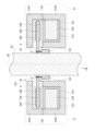
- the four diodes D are provided on the surface of the substrate 23A facing in the direction opposite to the Z direction, as shown in Figs. 4 and 5, but the present invention is not limited to this. Instead of this, the four diodes D may be provided on the surface of the substrate 23A facing in the Z direction, as shown in Fig. 9. Also, as shown in Figs. 10 and 11, a cutout may be provided in a part of the substrate 23A, and the four diodes D may be provided in this cutout.
- the substrate 23A has four cutouts 23C at four positions surrounding the shaft 24. The four diodes D are provided in each of the four cutouts 23C and mounted so as to be in contact with the shaft 24.
- the four diodes D are individually mounted as shown in Fig. 7, but the present invention is not limited to this. Instead, for example, when a rectifier circuit 23B including four diodes D is housed in one package, the rectifier circuit 23B may be mounted so as to be in contact with the shaft 24 as shown in Fig. 12.
- the four diodes D are mounted in contact with the shaft 24, thereby allowing the four diodes D to dissipate heat effectively.
- a cooling medium such as oil may be caused to flow inside the shaft 24.
- a flow path 24A for flowing a cooling medium such as oil is provided inside the shaft 24.
- the magnetic core 21A is provided with the opening 123, but this is not limited thereto, and instead, as shown in FIG. 14, for example, other openings may be provided.
- the magnetic core 21A1 has a plate shape.
- the magnetic core 21A having the magnetic core 21A1 and the magnetic core 21A2 is provided with an opening 124 that connects the space outside the magnetic core 21A in the radial direction of the rotation axis AZ (horizontal direction in FIG. 14) with the cavity 122.
- a gap G is provided between the magnetic core 21A1 and the magnetic core 21A2.
- the magnetic core 21A1 and the magnetic core 21A2 are magnetically coupled to each other through the gap G at the opening 123, and are also magnetically coupled to each other through the gap G at the opening 124.
- a motor device 2 according to a second embodiment will be described.
- the rotor 22 and the rectifying member 23 are integrally configured in the power transmission device 20 according to the first embodiment. Note that components that are substantially the same as those in the motor device 1 according to the first embodiment are given the same reference numerals, and descriptions thereof will be omitted as appropriate.
- FIG. 15 shows an example of the configuration of the motor device 2.
- the motor device 2 includes a drive unit 40 and a motor 30.
- the drive unit 40 includes a power transmission device 50.
- the power transmission device 50 includes a stator 21, a rotor 52, and a shaft 24.
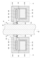
- FIGS. 16 and 17 show an example of the configuration of the power transmission device 50.
- FIG. 18 shows an example of the cross-sectional structure of the power transmission device 50 in a plane including the rotation axis AZ.
- FIG. 19 shows an example of the configuration of the rotor 52.
- the rotor 52 has a substrate 52A, a winding 22B, and four diodes D (diodes D1 to D4).
- the substrate 52A is, for example, a printed circuit board.
- the substrate 52A is connected to the shaft 24, and rotates in the circumferential direction A about the rotation axis AZ in response to the rotation of the shaft 24.
- the substrate 52A is provided with a winding 22B.
- the substrate 52A also has four diodes D (diodes D1 to D4 shown in FIG. 2) mounted thereon, and is provided with pattern wiring for a rectifier circuit 23B (FIG. 2) including these four diodes D.
- the four diodes D are mounted at four positions surrounding the shaft 24 so as to be in contact with the shaft 24.
- each of the four diodes D is mounted on the board 52A by so-called through-hole mounting.
- the four diodes D may also be mounted on the board surface of the board 52A by so-called surface mounting.
- the rectifier circuit 23B including the four diodes D rectifies the AC voltage supplied from the winding 22B of the rotor 52.
- the four diodes D are mounted so as to be in contact with the shaft 24.
- the heat generated in the four diodes D is transmitted over a wide area via the shaft 24 and dissipated.
- the power transmission device 50 can effectively dissipate heat from the four diodes D, reducing the possibility of the power transmission device 50 malfunctioning or breaking down, and improving reliability.
- the centrifugal force acting on the four diodes D when the shaft 24 rotates around the rotation axis AZ can be reduced.
- the power transmission device 50 can reduce the stress acting on the four diodes D and on the solder between the four diodes D and the substrate 52A, thereby improving reliability.
- the four diodes D are provided on the first rotating member (substrate 52A).
- the four diodes D are surrounded by the magnetic core 21A. Therefore, noise radiation from the vicinity of the four diodes D caused by switching operations is shielded to some extent by the magnetic core 21A. As a result, the power transmission device 50 can suppress noise radiation.
- the four diodes D are provided on the surface of the substrate 52A facing in the direction opposite to the Z direction, as shown in Figs. 17 and 18, for example, but the present invention is not limited to this. Instead of this, the four diodes D may be provided on the surface of the substrate 52A facing in the Z direction, as shown in Fig. 20. Also, as shown in Figs. 21 and 22, a cutout may be provided in a part of the substrate 52A, and the four diodes D may be provided in this cutout.
- the substrate 52A has four cutouts 52C at four positions surrounding the shaft 24. The four diodes D are provided in each of these four cutouts 52C and mounted so as to be in contact with the shaft 24.
- the four diodes D are individually mounted as shown in Fig. 19, but the present invention is not limited to this. Instead, for example, in the same manner as in the case of the modified example 1-2 of the first embodiment (Fig. 12), when the rectifier circuit 23B including the four diodes D is accommodated in one package, the rectifier circuit 23B may be mounted so as to be in contact with the shaft 24.
- the four diodes D are mounted in contact with the shaft 24 to effectively dissipate heat from the four diodes D.
- a cooling medium such as oil may be caused to flow inside the shaft 24.
- the magnetic core 21A is provided with an opening 123, but this is not limited to this, and instead, the magnetic core 21A may have further openings, for example as in the case of variant 1-4 of the first embodiment (FIG. 14).
- four diodes D are provided in the rectifier circuit 23B, but this is not limited to this.
- four switching elements may be provided as rectifier elements in the rectifier circuit 23B, and the four switching elements in the rectifier circuit 23B may be operated in synchronization with the switching operation of the four switching elements SW1 to SW4 in the inverter 12.
- the four switching elements in the rectifier circuit 23B are provided so as to be in contact with the shaft 24.
- the circuit configuration of the rectifier circuit 23B shown in each of the above embodiments is merely an example, and is not limited to the disclosed circuit configuration.
- the rectifier circuit may have one diode or multiple diodes.
- stator 21 and rotors 22, 52 shown in the above embodiments are merely examples and are not limited to the shapes disclosed.
- circuit configurations of the inverter 12 and the rectifier circuit 23B shown in the above embodiments are merely examples and are not limited to the disclosed circuit configurations.
- a magnetic core having a ring shape including a through hole through which a shaft passes, including a cavity along a circumferential direction of a rotation axis of the shaft, and an opening provided along the circumferential direction on a surface in contact with the through hole and connecting the through hole and the cavity; a first winding provided in the cavity and wound along the circumferential direction; a first rotating member provided at a position corresponding to the opening in the axial direction of the rotating shaft, the first rotating member being rotatable in the circumferential direction within the cavity in response to rotation of the shaft; a second winding provided on the first rotating member and wound in the circumferential direction; and one or more rectifying elements provided in contact with the shaft and connected to the second winding.
- the second rotating member has a first surface facing the magnetic core and a second surface opposite to the first surface, The power transfer device according to (2), wherein the one or more rectifying elements are provided on the first surface or the second surface.
- the second rotating member has a plurality of notches provided at a position where the second rotating member is in contact with the shaft, The power transfer device according to (2), wherein the one or more rectifying elements are provided in each of the plurality of cutout portions.
- the power transfer device according to any one of (2) to (4), wherein the second rotating member is a printed circuit board.
- the first rotating member has a first surface and a second surface opposite the first surface;
- the power transfer device according to (6), wherein the one or more rectifying elements are provided on the first surface or the second surface.
- the first rotating member has a plurality of notches provided at positions where the first rotating member is in contact with the shaft, The power transfer device according to (6), wherein the one or more rectifying elements are provided in each of the plurality of cutout portions.
- the power transfer device according to any one of (6) to (8), wherein the first rotating member is a printed circuit board.
- a motor having a motor stator including a first motor magnetic core and a first motor winding, and a motor rotor including a second motor magnetic core and a second motor winding; a shaft connected to the motor rotor; An inverter; a magnetic core having a ring shape including a through hole through which the shaft passes, including a cavity along a circumferential direction of the shaft, and an opening provided along the circumferential direction on a surface in contact with the through hole and connecting the through hole and the cavity; a first winding connected to the inverter, provided in the cavity, and wound in the circumferential direction; a first rotating member provided at a position corresponding to the opening in the axial direction of the shaft, the first rotating member being rotatable in the circumferential direction within the cavity in response to rotation of the shaft; a second winding provided on the first rotating member and wound in the circumferential direction;
Landscapes
- Engineering & Computer Science (AREA)
- Power Engineering (AREA)
- Synchronous Machinery (AREA)
Abstract
Description
1.第1の実施の形態
2.第2の実施の形態
[構成例]
図1は、本発明の第1の実施の形態に係る電力伝送デバイスを備えたモータ装置1の一構成例を表すものである。モータ装置1は、外部制御装置8および直流電源9に接続される。外部制御装置8は、モータ装置1に対して、回転速度を指示するように構成される。直流電源9は、モータ装置1に対して直流電力を供給するように構成される。モータ装置1は、直流電源9から供給された直流電力を用いて、外部制御装置8からの指示に基づいて、機械的エネルギである駆動力を生成するように構成される。モータ装置1は、駆動部10と、モータ30とを備えている。
続いて、本実施の形態のモータ装置1の動作および作用について説明する。
制御回路19は、外部制御装置8からの指示、およびモータ30から供給された回転速度を示す制御信号に基づいて、インバータ11,12の動作を制御する。インバータ11は、制御回路19からの指示に基づいて、直流電源9から供給された直流電力を3相(U相、V相、W相)の交流電力に変換し、この3相の交流電力を、モータ30の固定子31の巻線31Bに供給する。インバータ12は、制御回路19からの指示に基づいて、直流電源9から供給された直流電力を単相の交流電力に変換し、この交流電力を、電力伝送デバイス20の固定子21の巻線21Bに供給する。電力伝送デバイス20は、非接触伝送により、インバータ12から供給された交流電力を固定子21から回転子22に伝送し、伝送された交流電力を整流する。そして、電力伝送デバイス20は、整流された電力をモータ30の回転子32の巻線32Bに供給する。モータ30は、インバータ11から供給された3相(U相、V相、W相)の交流電力に基づいて、機械的エネルギである駆動力を生成する。これにより、シャフト24が回転軸AZを中心に回転する。モータ30のセンサ33は、モータ30の回転速度を示す制御信号を制御回路19に供給する。
続いて、本実施の形態の電力伝送デバイス20の動作および作用について説明する。
以上のように本実施の形態では、シャフトが貫く貫通穴を含むリング形状を有し、シャフトにおける回転軸の周方向に沿った空洞を内部に含み、貫通穴と接する面において周方向に沿って設けられ貫通穴と空洞とをつなぐ開口部を有する磁気コアと、空洞に設けられ、周方向に沿って巻かれた第1の巻線と、回転軸の軸方向における開口部に対応する位置に設けられ、シャフトの回転に応じて、空洞の内部において周方向に回動可能な第1の回転部材と、第1の回転部材に設けられ、周方向に沿って巻かれた第2の巻線と、シャフトに接するように設けられ、第2の巻線に接続された4つのダイオードとを設けるようにしたので、信頼性を高めることができる。
上記実施の形態では、例えば図4,5に示したように、4つのダイオードDを、基板23Aの、Z方向とは反対の方向の面に設けたが、これに限定されるものではない。これに代えて、例えば、図9に示すように、4つのダイオードDを、基板23AのZ方向の面に設けてもよい。また、図10,11に示すように、基板23Aの一部に切り欠き部を設け、4つのダイオードDを、この切り欠き部に設けてもよい。基板23Aは、シャフト24を囲む4つの位置に、4つの切り欠き部23Cを有している。4つのダイオードDは、これらの4つの切り欠き部23Cにそれぞれ設けられ、シャフト24に接するように実装される。
上記実施の形態では、例えば図7に示したように、4つのダイオードDを、個別に実装したが、これに限定されるものではない。これに代えて、例えば、4つのダイオードDを含む整流回路23Bが1つのパッケージに収められている場合には、図12に示すように、この整流回路23Bを、シャフト24に接するように実装してもよい。
上記実施の形態では、4つのダイオードDをシャフト24に接するように実装することにより、4つのダイオードDを効果的に放熱させるようにした。例えば、図13に示すように、このシャフト24の内部に、油などの冷却媒体を流してもよい。この例では、シャフト24の内部に、油などの冷却媒体を流す流路24Aが設けられている。このような流路24Aに冷却媒体を流すことにより、4つのダイオードDをさらに効果的に放熱させることができる。
上記実施の形態では、図5に示したように、磁気コア21Aは、開口部123を設けるようにしたが、これに限定されるものではなく、これに代えて、例えば図14に示すように、さらに他の開口部を有していてもよい。この例では、磁気コア21A1は板形状を有している。この構成により、磁気コア21A1および磁気コア21A2を有する磁気コア21Aには、回転軸AZの径方向(図14における横方向)における磁気コア21Aの外側の空間と空洞122とをつなぐ開口部124が設けられる。この開口部124では、磁気コア21A1と磁気コア21A2との間にギャップGが設けられる。磁気コア21A1および磁気コア21A2は、開口部123において、ギャップGを介して、互いに磁気的に結合されるとともに、この開口部124において、ギャップGを介して、互いに磁気的に結合される。
また、これらの変形例のうちの2以上を組み合わせてもよい。
次に、第2の実施の形態に係るモータ装置2について説明する。本実施の形態は、上記第1の実施の形態に係る電力伝送デバイス20において、回転子22および整流部材23を一体として構成したものである。なお、上記第1の実施の形態に係るモータ装置1と実質的に同一の構成部分には同一の符号を付し、適宜説明を省略する。
上記実施の形態では、例えば図17,18に示したように、4つのダイオードDを、基板52Aの、Z方向とは反対の方向の面に設けたが、これに限定されるものではない。これに代えて、例えば、図20に示すように、4つのダイオードDを、基板52AのZ方向の面に設けてもよい。また、図21,22に示すように、基板52Aの一部に切り欠き部を設け、4つのダイオードDを、この切り欠き部に設けてもよい。基板52Aは、シャフト24を囲む4つの位置に、4つの切り欠き部52Cを有している。4つのダイオードDは、これらの4つの切り欠き部52Cにそれぞれ設けられ、シャフト24に接するように実装される。
上記実施の形態では、例えば図19に示したように、4つのダイオードDを、個別に実装したが、これに限定されるものではない。これに代えて、例えば、上記第1の実施の形態の変形例1-2の場合(図12)と同様に、4つのダイオードDを含む整流回路23Bが1つのパッケージに収められている場合には、この整流回路23Bを、シャフト24に接するように実装してもよい。
上記実施の形態では、4つのダイオードDをシャフト24に接するように実装することにより、4つのダイオードDを効果的に放熱させるようにした。例えば、上記第1の実施の形態の変形例1-3の場合(図13)と同様に、このシャフト24の内部に、油などの冷却媒体を流してもよい。
上記実施の形態では、図18に示したように、磁気コア21Aは、開口部123を設けるようにしたが、これに限定されるものではなく、これに代えて、例えば上記第1の実施の形態の変形例1-4の場合(図14)と同様に、さらに他の開口部を有していてもよい。
また、これらの変形例のうちの2以上を組み合わせてもよい。
シャフトが貫く貫通穴を含むリング形状を有し、前記シャフトにおける回転軸の周方向に沿った空洞を内部に含み、前記貫通穴と接する面において前記周方向に沿って設けられ前記貫通穴と前記空洞とをつなぐ開口部を有する磁気コアと、
前記空洞に設けられ、前記周方向に沿って巻かれた第1の巻線と、
前記回転軸の軸方向における前記開口部に対応する位置に設けられ、前記シャフトの回転に応じて、前記空洞の内部において前記周方向に回動可能な第1の回転部材と、
前記第1の回転部材に設けられ、前記周方向に沿って巻かれた第2の巻線と、
前記シャフトに接するように設けられ、前記第2の巻線に接続された1以上の整流素子と
を備えた電力伝送デバイス。
(2)
前記回転軸の軸方向において、前記磁気コアが設けられた位置とは異なる位置に設けられ、前記シャフトの回転に応じて、前記周方向に回動可能な第2の回転部材をさらに備え、
前記1以上の整流素子は、前記第2の回転部材に設けられた
前記(1)に記載の電力伝送デバイス。
(3)
前記第2の回転部材は、前記磁気コアと対向する第1の面と、前記第1の面とは反対の第2の面とを有し、
前記1以上の整流素子は、前記第1の面または前記第2の面に設けられた
前記(2)に記載の電力伝送デバイス。
(4)
前記第2の回転部材は、前記シャフトに接する位置に設けられた複数の切り欠き部を有し、
前記1以上の整流素子は、前記複数の切り欠き部にそれぞれ設けられた
前記(2)に記載の電力伝送デバイス。
(5)
前記第2の回転部材は、プリント基板である
前記(2)から(4)のいずれかに記載の電力伝送デバイス。
(6)
前記1以上の整流素子は、前記第1の回転部材に設けられた
前記(1)に記載の電力伝送デバイス。
(7)
前記第1の回転部材は、第1の面と、前記第1の面とは反対の第2の面とを有し、
前記1以上の整流素子は、前記第1の面または前記第2の面に設けられた
前記(6)に記載の電力伝送デバイス。
(8)
前記第1の回転部材は、前記シャフトに接する位置に設けられた複数の切り欠き部を有し、
前記1以上の整流素子は、前記複数の切り欠き部にそれぞれ設けられた
前記(6)に記載の電力伝送デバイス。
(9)
前記第1の回転部材は、プリント基板である
前記(6)から(8)のいずれかに記載の電力伝送デバイス。
(10)
第1のモータ磁気コアおよび第1のモータ巻線を含むモータ固定子と、第2のモータ磁気コアおよび第2のモータ巻線を含むモータ回転子とを有するモータと、
前記モータ回転子に接続されたシャフトと、
インバータと、
前記シャフトが貫く貫通穴を含むリング形状を有し、前記シャフトの周方向に沿った空洞を内部に含み、前記貫通穴と接する面において前記周方向に沿って設けられ前記貫通穴と前記空洞とをつなぐ開口部を有する磁気コアと、
前記インバータに接続され、前記空洞に設けられ、前記周方向に沿って巻かれた第1の巻線と、
前記シャフトの軸方向における前記開口部に対応する位置に設けられ、前記シャフトの回転に応じて、前記空洞の内部において前記周方向に回動可能な第1の回転部材と、
前記第1の回転部材に設けられ、前記周方向に沿って巻かれた第2の巻線と、
前記シャフトに接するように設けられ、前記第2の巻線に接続され、前記第2の巻線および前記第2のモータ巻線を結ぶ経路に設けられた1以上の整流素子と
を備えたモータ装置。
Claims (10)
- シャフトが貫く貫通穴を含むリング形状を有し、前記シャフトにおける回転軸の周方向に沿った空洞を内部に含み、前記貫通穴と接する面において前記周方向に沿って設けられ前記貫通穴と前記空洞とをつなぐ開口部を有する磁気コアと、
前記空洞に設けられ、前記周方向に沿って巻かれた第1の巻線と、
前記回転軸の軸方向における前記開口部に対応する位置に設けられ、前記シャフトの回転に応じて、前記空洞の内部において前記周方向に回動可能な第1の回転部材と、
前記第1の回転部材に設けられ、前記周方向に沿って巻かれた第2の巻線と、
前記シャフトに接するように設けられ、前記第2の巻線に接続された1以上の整流素子と
を備えた電力伝送デバイス。 - 前記回転軸の軸方向において、前記磁気コアが設けられた位置とは異なる位置に設けられ、前記シャフトの回転に応じて、前記周方向に回動可能な第2の回転部材をさらに備え、
前記1以上の整流素子は、前記第2の回転部材に設けられた
請求項1に記載の電力伝送デバイス。 - 前記第2の回転部材は、前記磁気コアと対向する第1の面と、前記第1の面とは反対の第2の面とを有し、
前記1以上の整流素子は、前記第1の面または前記第2の面に設けられた
請求項2に記載の電力伝送デバイス。 - 前記第2の回転部材は、前記シャフトに接する位置に設けられた複数の切り欠き部を有し、
前記1以上の整流素子は、前記複数の切り欠き部にそれぞれ設けられた
請求項2に記載の電力伝送デバイス。 - 前記第2の回転部材は、プリント基板である
請求項2に記載の電力伝送デバイス。 - 前記1以上の整流素子は、前記第1の回転部材に設けられた
請求項1に記載の電力伝送デバイス。 - 前記第1の回転部材は、第1の面と、前記第1の面とは反対の第2の面とを有し、
前記1以上の整流素子は、前記第1の面または前記第2の面に設けられた
請求項6に記載の電力伝送デバイス。 - 前記第1の回転部材は、前記シャフトに接する位置に設けられた複数の切り欠き部を有し、
前記1以上の整流素子は、前記複数の切り欠き部にそれぞれ設けられた
請求項6に記載の電力伝送デバイス。 - 前記第1の回転部材は、プリント基板である
請求項6に記載の電力伝送デバイス。 - 第1のモータ磁気コアおよび第1のモータ巻線を含むモータ固定子と、第2のモータ磁気コアおよび第2のモータ巻線を含むモータ回転子とを有するモータと、
前記モータ回転子に接続されたシャフトと、
インバータと、
前記シャフトが貫く貫通穴を含むリング形状を有し、前記シャフトの周方向に沿った空洞を内部に含み、前記貫通穴と接する面において前記周方向に沿って設けられ前記貫通穴と前記空洞とをつなぐ開口部を有する磁気コアと、
前記インバータに接続され、前記空洞に設けられ、前記周方向に沿って巻かれた第1の巻線と、
前記シャフトの軸方向における前記開口部に対応する位置に設けられ、前記シャフトの回転に応じて、前記空洞の内部において前記周方向に回動可能な第1の回転部材と、
前記第1の回転部材に設けられ、前記周方向に沿って巻かれた第2の巻線と、
前記シャフトに接するように設けられ、前記第2の巻線に接続され、前記第2の巻線および前記第2のモータ巻線を結ぶ経路に設けられた1以上の整流素子と
を備えたモータ装置。
Priority Applications (4)
| Application Number | Priority Date | Filing Date | Title |
|---|---|---|---|
| PCT/JP2023/020786 WO2024252455A1 (ja) | 2023-06-05 | 2023-06-05 | 電力伝送デバイスおよびモータ装置 |
| JP2025525432A JPWO2024252455A1 (ja) | 2023-06-05 | 2023-06-05 | |
| EP23940563.2A EP4723150A1 (en) | 2023-06-05 | 2023-06-05 | Power transmission device and motor apparatus |
| CN202380099135.5A CN121285867A (zh) | 2023-06-05 | 2023-06-05 | 电力传送器件和电动机装置 |
Applications Claiming Priority (1)
| Application Number | Priority Date | Filing Date | Title |
|---|---|---|---|
| PCT/JP2023/020786 WO2024252455A1 (ja) | 2023-06-05 | 2023-06-05 | 電力伝送デバイスおよびモータ装置 |
Publications (1)
| Publication Number | Publication Date |
|---|---|
| WO2024252455A1 true WO2024252455A1 (ja) | 2024-12-12 |
Family
ID=93795241
Family Applications (1)
| Application Number | Title | Priority Date | Filing Date |
|---|---|---|---|
| PCT/JP2023/020786 Ceased WO2024252455A1 (ja) | 2023-06-05 | 2023-06-05 | 電力伝送デバイスおよびモータ装置 |
Country Status (4)
| Country | Link |
|---|---|
| EP (1) | EP4723150A1 (ja) |
| JP (1) | JPWO2024252455A1 (ja) |
| CN (1) | CN121285867A (ja) |
| WO (1) | WO2024252455A1 (ja) |
Citations (4)
| Publication number | Priority date | Publication date | Assignee | Title |
|---|---|---|---|---|
| WO1993026020A1 (fr) * | 1992-06-18 | 1993-12-23 | Kabushiki Kaisha Yaskawa Denki | Appareil de transmission de puissance sans contact, emetteur de signaux sans contact, machine du type a separation les utilisant et leur procede de commande |
| JP2002075760A (ja) | 2000-08-29 | 2002-03-15 | Tamagawa Seiki Co Ltd | 回転型非接触コネクタ及び非回転型非接触コネクタ |
| JP2010130777A (ja) * | 2008-11-27 | 2010-06-10 | Toshiba Corp | ブラシレスモータ |
| WO2013001559A1 (ja) * | 2011-06-27 | 2013-01-03 | 株式会社 日立製作所 | 回転電機 |
-
2023
- 2023-06-05 JP JP2025525432A patent/JPWO2024252455A1/ja active Pending
- 2023-06-05 CN CN202380099135.5A patent/CN121285867A/zh active Pending
- 2023-06-05 EP EP23940563.2A patent/EP4723150A1/en active Pending
- 2023-06-05 WO PCT/JP2023/020786 patent/WO2024252455A1/ja not_active Ceased
Patent Citations (4)
| Publication number | Priority date | Publication date | Assignee | Title |
|---|---|---|---|---|
| WO1993026020A1 (fr) * | 1992-06-18 | 1993-12-23 | Kabushiki Kaisha Yaskawa Denki | Appareil de transmission de puissance sans contact, emetteur de signaux sans contact, machine du type a separation les utilisant et leur procede de commande |
| JP2002075760A (ja) | 2000-08-29 | 2002-03-15 | Tamagawa Seiki Co Ltd | 回転型非接触コネクタ及び非回転型非接触コネクタ |
| JP2010130777A (ja) * | 2008-11-27 | 2010-06-10 | Toshiba Corp | ブラシレスモータ |
| WO2013001559A1 (ja) * | 2011-06-27 | 2013-01-03 | 株式会社 日立製作所 | 回転電機 |
Also Published As
| Publication number | Publication date |
|---|---|
| EP4723150A1 (en) | 2026-04-08 |
| CN121285867A (zh) | 2026-01-06 |
| JPWO2024252455A1 (ja) | 2024-12-12 |
Similar Documents
| Publication | Publication Date | Title |
|---|---|---|
| US20250233489A1 (en) | Rotor arrangement for a separately excited synchronous machine | |
| US7230363B2 (en) | Low profile generator configuration | |
| JP5039171B2 (ja) | 電動式駆動装置およびその電動式駆動装置を搭載した電動式パワーステアリング装置 | |
| JP2024537447A (ja) | 他励同期機用ロータ | |
| US8110954B2 (en) | Electric rotating machine | |
| US7663277B2 (en) | Inner-rotor-type brushless motor having built-in bus bar | |
| JP4628460B2 (ja) | 回転電機、及びその製造方法 | |
| JP6130084B1 (ja) | 回転電機 | |
| JP7399351B2 (ja) | 制御装置、駆動装置、および電動パワーステアリング装置 | |
| JP2018157612A (ja) | モータ | |
| JP2019057968A (ja) | 電力変換装置及び制御装置一体型回転電機 | |
| JP6408059B2 (ja) | 回転電機 | |
| WO2024252455A1 (ja) | 電力伝送デバイスおよびモータ装置 | |
| WO2024252539A1 (ja) | 電力伝送デバイスおよびモータ装置 | |
| CN213243690U (zh) | 马达以及电动泵 | |
| WO2025181973A1 (ja) | 電力伝送デバイスおよびモータ装置 | |
| WO2024171299A1 (ja) | 電力伝送デバイスおよびモータ装置 | |
| WO2024171300A1 (ja) | 電力伝送デバイスおよびモータ装置 | |
| CN214380580U (zh) | 永磁电机及电机设备 | |
| TWI772833B (zh) | 旋轉電機 | |
| WO2017145613A1 (ja) | アキシャルギャップ型回転電機 | |
| JP2026060048A (ja) | 電力伝送デバイスおよびモータ装置 | |
| WO2024154191A1 (ja) | 電力伝送デバイスおよびモータ装置 | |
| JP2020055067A (ja) | スピンドルモータおよび主軸装置 | |
| JP2024041397A (ja) | モータ |
Legal Events
| Date | Code | Title | Description |
|---|---|---|---|
| 121 | Ep: the epo has been informed by wipo that ep was designated in this application |
Ref document number: 23940563 Country of ref document: EP Kind code of ref document: A1 |
|
| ENP | Entry into the national phase |
Ref document number: 2025525432 Country of ref document: JP Kind code of ref document: A |
|
| WWE | Wipo information: entry into national phase |
Ref document number: 2023940563 Country of ref document: EP |
|
| NENP | Non-entry into the national phase |
Ref country code: DE |
|
| ENP | Entry into the national phase |
Ref document number: 2023940563 Country of ref document: EP Effective date: 20260105 |
|
| ENP | Entry into the national phase |
Ref document number: 2023940563 Country of ref document: EP Effective date: 20260105 |
|
| ENP | Entry into the national phase |
Ref document number: 2023940563 Country of ref document: EP Effective date: 20260105 |
|
| ENP | Entry into the national phase |
Ref document number: 2023940563 Country of ref document: EP Effective date: 20260105 |
|
| WWP | Wipo information: published in national office |
Ref document number: 2023940563 Country of ref document: EP |