WO2024252468A1 - Refrigeration cycle device - Google Patents
Refrigeration cycle device Download PDFInfo
- Publication number
- WO2024252468A1 WO2024252468A1 PCT/JP2023/020814 JP2023020814W WO2024252468A1 WO 2024252468 A1 WO2024252468 A1 WO 2024252468A1 JP 2023020814 W JP2023020814 W JP 2023020814W WO 2024252468 A1 WO2024252468 A1 WO 2024252468A1
- Authority
- WO
- WIPO (PCT)
- Prior art keywords
- refrigerant
- heat
- heat source
- temperature
- heat exchanger
- Prior art date
- Legal status (The legal status is an assumption and is not a legal conclusion. Google has not performed a legal analysis and makes no representation as to the accuracy of the status listed.)
- Ceased
Links
Images


Classifications
-
- F—MECHANICAL ENGINEERING; LIGHTING; HEATING; WEAPONS; BLASTING
- F25—REFRIGERATION OR COOLING; COMBINED HEATING AND REFRIGERATION SYSTEMS; HEAT PUMP SYSTEMS; MANUFACTURE OR STORAGE OF ICE; LIQUEFACTION SOLIDIFICATION OF GASES
- F25B—REFRIGERATION MACHINES, PLANTS OR SYSTEMS; COMBINED HEATING AND REFRIGERATION SYSTEMS; HEAT PUMP SYSTEMS
- F25B30/00—Heat pumps
- F25B30/06—Heat pumps characterised by the source of low potential heat
Definitions
- Patent Document 1 Conventionally, it has been proposed to utilize so-called renewable energy such as geothermal heat in refrigeration cycle devices such as air conditioners (for example, Patent Document 1).
- the air conditioner of Patent Document 1 has a heat exchanger for exchanging heat between the heat source having renewable energy and the refrigerant in addition to the heat exchanger of the heat source unit, thereby increasing the total heat transfer area. In this way, the air conditioner of Patent Document 1 aims to improve the air conditioning capacity.
- Patent Document 1 even though the total heat transfer area has increased, some of the equipment is controlled in the same way as if there were no heat source with renewable energy. Therefore, the air conditioner in Patent Document 1 is operated at a capacity higher than necessary, resulting in unnecessary consumption of electricity.
- This disclosure has been made to solve the problems described above, and aims to provide a refrigeration cycle device that improves energy-saving performance.
- the refrigeration cycle device includes a heat source unit having a compressor that compresses a refrigerant, a heat source side heat exchanger that exchanges heat between the refrigerant and outdoor air, and a heat source side blower that supplies outdoor air to the heat source side heat exchanger; a load unit having a load side heat exchanger that exchanges heat between the refrigerant and a fluid that is to be heated or cooled; an auxiliary heat source unit having a heat medium heat exchanger that exchanges heat between the refrigerant and a heat medium that has heat derived from a renewable energy different from the outdoor air; and a control device that controls the rotation speed of the heat source side blower to within a first range that is a range of rotation speeds lower than the rotation speed during rated operation based on the comparison result between the temperature of the heat medium and the temperature of the outdoor air.
- the rotation speed of the heat source side blower is controlled to within a first range, which is a range of rotation speeds lower than the rotation speed during rated operation. Therefore, the refrigeration cycle device can reduce the power consumption related to the operation of the heat source side blower and improve energy saving performance.
- FIG. 2 is a refrigerant circuit diagram showing a flow of refrigerant during cooling operation of the refrigeration cycle device according to the first embodiment.
- FIG. FIG. 2 is a hardware configuration diagram showing a control device according to the first embodiment.
- FIG. 2 is a hardware configuration diagram showing a control device according to the first embodiment.
- 1 is a functional block diagram showing a refrigeration cycle device according to a first embodiment.
- FIG. 2 is a refrigerant circuit diagram showing a flow of a refrigerant during heating operation of the refrigeration cycle device according to the first embodiment.
- FIG. 5 is a flowchart showing a method for controlling the rotation speed of the heat source side blower according to the first embodiment.
- FIG. 11 is a refrigerant circuit diagram showing a flow of a refrigerant during heating operation of a refrigeration cycle device according to a second embodiment.
- FIG. 11 is a functional block diagram showing a refrigeration cycle device according to a second embodiment.
- FIG. 11 is a refrigerant circuit diagram showing a flow of refrigerant during cooling operation of a refrigeration cycle device according to a third embodiment.
- FIG. 11 is a functional block diagram showing a refrigeration cycle device according to a third embodiment.
- FIG. 11 is a refrigerant circuit diagram showing a flow of a refrigerant during heating operation of a refrigeration cycle device according to a third embodiment.
- FIG. 11 is a refrigerant circuit diagram showing a flow of a refrigerant during heating operation of a refrigeration cycle device according to a third embodiment.
- FIG. 11 is a refrigerant circuit diagram showing the flow of refrigerant during cooling operation of a refrigeration cycle device according to a fourth embodiment.
- FIG. 13 is a functional block diagram showing a refrigeration cycle device according to a fourth embodiment.
- FIG. 11 is a refrigerant circuit diagram showing a flow of a refrigerant during heating operation of a refrigeration cycle device according to a fourth embodiment.
- FIG. 11 is a refrigerant circuit diagram showing a flow of a refrigerant during heating operation of a refrigeration cycle device according to a fourth embodiment.
- FIG. 11 is a refrigerant circuit diagram showing a refrigeration cycle device according to a modified example.
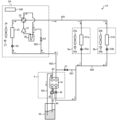
- FIG. 1 is a refrigerant circuit diagram showing the flow of refrigerant during cooling operation of a refrigeration cycle apparatus 1 according to embodiment 1.
- the refrigeration cycle apparatus 1 of embodiment 1 is an air conditioner that cools and heats a room.
- the refrigeration cycle apparatus 1 includes a heat source unit 2, load devices 3a and 3b, and an auxiliary heat source unit 4.
- the heat source unit 2 and the load devices 3a and 3b are connected by a first connection pipe 401.
- the load devices 3a and 3b are connected by a second connection pipe 402, and the auxiliary heat source unit 4 and the heat source unit 2 are connected by a third connection pipe 403.
- the refrigeration cycle device 1 is an air conditioner capable of performing at least cooling operation and heating operation as operating modes, but the refrigeration cycle device 1 may also be a refrigerator, freezer, or vending machine that cools stored items.
- the refrigeration cycle device 1 may also be a refrigeration device installed in a showcase or the like.
- the refrigeration cycle device 1 may also be a water heater that supplies hot water, or a chiller that supplies cold water.
- the refrigeration cycle device 1 may also be capable of performing operating modes other than cooling operation and heating operation, such as dehumidification operation.
- the heat source unit 2 is, for example, an outdoor unit installed outdoors.
- the heat source unit 2 is a device that supplies hot or cold heat to the load device 3.
- the heat source unit 2 has a compressor 21, a flow path switching device 22, a heat source side heat exchanger 23, a heat source side blower 24, a heat source side throttle device 25, an accumulator 26, and a control device 100.
- the compressor 21 draws in low-pressure gas refrigerant, compresses it, and discharges it as high-pressure gas refrigerant.
- a reciprocating, rotary, scroll, or screw compressor 21 is used as the compressor 21 for example.
- the flow path switching device 22 switches between cooling operation, in which the heat source side heat exchanger 23 functions as a condenser, and heating operation, in which the heat source side heat exchanger 23 functions as an evaporator.
- the flow path switching device 22 is, for example, a four-way valve, and is controlled by the control device 100.
- the flow path switching device 22 is switched so that the refrigerant discharged from the compressor 21 flows into the heat source side heat exchanger 23.
- the flow path switching device 22 is switched so that the refrigerant discharged from the compressor 21 flows into the load devices 3a and 3b.
- the heat source side heat exchanger 23 is, for example, a fin tube type heat exchanger, and exchanges heat between the refrigerant flowing inside the circular or flat tubes and the outdoor air supplied by the heat source side blower 24.
- the heat source side heat exchanger 23 functions as an evaporator during heating operation and as a condenser during cooling operation.
- the heat source side blower 24 is a device that sends outdoor air to the heat source side heat exchanger 23.
- the heat source side blower 24 is disposed adjacent to the heat source side heat exchanger 23. By sending outdoor air from the heat source side blower 24, the efficiency of heat exchange between the refrigerant and the outdoor air is improved.
- a propeller fan, a line flow fan (registered trademark), or a multi-blade centrifugal fan is used as the heat source side blower 24, a propeller fan, a line flow fan (registered trademark), or a multi-blade centrifugal fan is used.
- the heat source side throttle device 25 is an electronic expansion valve with an adjustable opening.
- the heat source side throttle device 25 reduces the pressure of the refrigerant flowing into the heat source side heat exchanger 23 or the refrigerant flowing out from the heat source side heat exchanger 23, causing it to expand.
- the opening of the heat source side throttle device 25 is controlled by the control device 100.
- the accumulator 26 stores excess refrigerant depending on the operating state.
- the accumulator 26 is connected to the intake port of the compressor 21 and the flow path switching device 22, and separates the refrigerant that flows in through the flow path switching device 22 into gas refrigerant and liquid refrigerant, stores the liquid refrigerant, and allows the gas refrigerant to flow to the compressor 21. Note that the accumulator 26 is not a required component and may be omitted.
- FIG. 2 is a hardware configuration diagram showing the control device 100 according to the first embodiment.
- the control device 100 is dedicated hardware configured with a processing circuit 101 such as an ASIC (Application Specific Integrated Circuit) or an FPGA (Field-Programmable Gate Array).
- FIG. 3 is a hardware configuration diagram showing the control device 100 according to the first embodiment.
- the control device 100 may be configured with a processor 102 such as a CPU and a memory 103 as shown in FIG. 3.
- FIG. 3 shows that the processor 102 and the memory 103 are connected to each other so as to be able to communicate with each other via a bus 104.
- the functions of the control device 100 are realized by the processor 102 reading and executing a program stored in the memory 103.
- the memory 103 may be a non-volatile or volatile semiconductor memory, or a removable recording medium. The functions of the control device 100 will be described later.
- control device 100 is provided in the heat source device 2, but the control device 100 may be provided in the load device 3a or 3b, or the heat source device 2 and the load devices 3a and 3b may each be provided with a separate control device 100 that communicates with each other.
- the control device 100 may also be provided in a location away from the heat source device 2 and the load device 3.
- the load devices 3a and 3b are, for example, indoor units installed in a room.
- the load devices 3a and 3b receive cold or hot heat via refrigerant from the heat source device 2 and the auxiliary heat source device 4 to air-condition the room.
- the load device 3a has a load side heat exchanger 31a, a load side blower 32, and a load side throttling device 33a.
- the load device 3b has a load side heat exchanger 31b, a load side blower 32, and a load side throttling device 33b.
- the load side heat exchanger 31 is, for example, a fin tube type heat exchanger, and exchanges heat between the refrigerant flowing inside the circular or flat tubes and the indoor air supplied by the load side blower 32.
- the load side heat exchanger 31 functions as a condenser during heating operation, and as an evaporator during cooling operation. If the refrigeration cycle device 1 is, for example, a chiller, the load side heat exchanger 31 may exchange heat between the refrigerant and water to supply cold water. If the refrigeration cycle device 1 is, for example, a water heater, the load side heat exchanger 31 may exchange heat between the refrigerant and water to supply hot water.
- the fluid that exchanges heat with the refrigerant in the load side heat exchanger 31 corresponds to the "fluid" in this disclosure.
- the refrigeration cycle device 1 which is an air conditioner
- the air in the air-conditioned space in which the load device 3 is installed is the "cooling target” of this disclosure.
- the refrigeration cycle device 1, which is a chiller supplies cold water
- the water flowing through the load side heat exchanger 31 is the "cooling target” of this disclosure.
- the refrigeration cycle device 1, which is an air conditioner performs heating operation
- the air in the air-conditioned space in which the load device 3 is installed is the “heating target” of this disclosure.
- the refrigeration cycle device 1, which is a water heater supplies hot water
- the water flowing through the load side heat exchanger 31 is the "heating target” of this disclosure.
- the load side blower 32 is a device that sends indoor air to the load side heat exchanger 31.
- the load side blower 32 is disposed adjacent to the load side heat exchanger 31. By sending indoor air from the load side blower 32, the efficiency of heat exchange between the refrigerant and the indoor air is improved.
- a propeller fan, a line flow fan (registered trademark), or a multi-blade centrifugal fan is used as the load side blower 32. Note that, if the load side heat exchanger 31 exchanges heat between a fluid such as water and a refrigerant, a pump that circulates water or the like may be used instead of the load side blower 32.
- the load side throttle device 33 is an electronic expansion valve whose opening is adjustable.
- the load side throttle device 33 reduces the pressure of the refrigerant flowing into the load side heat exchanger 31 or the refrigerant flowing out from the load side heat exchanger 31, causing it to expand.
- the opening of the load side throttle device 33 is controlled by the control device 100.
- the auxiliary heat source unit 4 is a device that supplies hot or cold heat to the load device 3. As will be described in detail later, the auxiliary heat source unit 4 uses renewable energy as a heat source and performs an auxiliary function to the heat source unit 2.
- the auxiliary heat source unit 4 has a heat medium heat exchanger 41, an auxiliary side throttle device 42, and a pump 43.
- the heat medium heat exchanger 41 is, for example, a plate-type heat exchanger, and performs heat exchange between the refrigerant and the heat medium.
- the heat medium heat exchanger 41 has a refrigerant flow path (not shown) through which the refrigerant flows, and a heat medium flow path (not shown) through which the heat medium flows.
- the compressor 21, flow path switching device 22, heat source side heat exchanger 23, and heat source side throttling device 25 of the heat source unit 2, the load side heat exchanger 31 and load side throttling device 33 of the load unit 3, and the refrigerant flow path and auxiliary side throttling device 42 of the heat medium heat exchanger 41 of the auxiliary heat source unit 4 are connected by a first connection pipe 401, a second connection pipe 402, and a third connection pipe 403 to form a refrigerant circuit.
- the refrigerant used is a fluid that undergoes latent heat change.
- the heat medium flow path of the heat medium heat exchanger 41 is connected to a tank 52 in which the heat medium is stored by a heat medium pipe 601.
- the heat medium is supplied to the heat medium flow path from the tank 52 via the heat medium pipe 601.
- a water circuit is formed by connecting the tank 52 and the heat medium flow path of the heat medium heat exchanger 41 by the heat medium pipe 601.
- the heat medium pipe 601 is provided with a pump 43 that circulates the heat medium in the water circuit.
- the pump 43 is, for example, an inverter-type centrifugal pump whose capacity can be controlled.
- the heat medium heat exchanger 41 acts as a condenser during cooling operation, exchanging heat between the refrigerant flowing through the refrigerant flow path and the heat medium flowing through the heat medium flow path, condensing and liquefying the refrigerant.
- the heat medium heat exchanger 41 acts as an evaporator during heating operation, exchanging heat between the refrigerant that has flowed inside and the heat medium, evaporating and vaporizing the refrigerant.
- the heat medium stored in the tank 52 is, for example, well water.
- Well water contains geothermal heat, which is a renewable energy contained in the earth.
- well water is a fluid that contains heat derived from geothermal heat
- the heat medium heat exchanger 41 uses the geothermal heat contained in the well water as a heat source.
- renewable energy means energy that is naturally replenished at a rate faster than it can be used.
- Solar heat may be used as the heat source used by the heat medium heat exchanger 41.
- the heat medium warmed by a solar panel or the like is stored in the tank 52.
- a specific heat medium is a fluid that undergoes latent heat change, such as a calcium chloride solution, a sodium chloride solution, a magnesium chloride solution, a brine containing ethylene glycol, an antifreeze, or water.
- the refrigeration cycle device 1 has a first bypass pipe 501 and a first bypass valve 51.
- the first bypass pipe 501 is a pipe that connects the second connection pipe 402 and the third connection pipe 403.
- the first bypass valve 51 is a valve provided in the first bypass pipe 501.
- the first bypass valve 51 is a valve that can be selectively switched between an open state that allows the flow of refrigerant through the first bypass pipe 501 and a closed state that blocks the flow of refrigerant through the first bypass pipe 501.
- the refrigeration cycle device 1 has an outdoor air temperature sensor 27, indoor temperature sensors 34a and 34b, a first heat medium temperature sensor 44, and a second heat medium temperature sensor 45.
- the outdoor air temperature sensor 27 is provided in the heat source unit 2.
- the outdoor air temperature sensor 27 is, for example, a thermistor, and measures the temperature of the air outside the room where the heat source unit 2 is provided.
- the indoor air temperature sensor 34 is provided in the load device 3.
- the indoor air temperature sensor 34 is, for example, a thermistor, and is a sensor that measures the temperature of the air in the room where the load device 3 is provided.
- the first heat medium temperature sensor 44 is provided on the heat medium pipe 601 upstream of the heat medium heat exchanger 41.
- the first heat medium temperature sensor 44 is, for example, a thermistor, and measures the temperature of the heat medium flowing into the heat medium heat exchanger 41.
- the second heat medium temperature sensor 45 is provided on the heat medium pipe 601 downstream of the heat medium heat exchanger 41.
- the second heat medium temperature sensor 45 is, for example, a thermistor, and measures the temperature of the heat medium flowing into the heat medium heat exchanger 41.
- heat medium temperature when simply referred to as "heat medium temperature,” it refers to the temperature of the heat medium flowing upstream of the heat medium heat exchanger 41.
- the outdoor air temperature sensor 27, the indoor temperature sensors 34a and 34b, the first heat medium temperature sensor 44, and the second heat medium temperature sensor 45 transmit the measurement results to the control device 100 connected by wire or wirelessly.
- the refrigeration cycle device 1 may also be equipped with temperature sensors or pressure sensors other than the outdoor air temperature sensor 27, the indoor temperature sensors 34a and 34b, the first heat medium temperature sensor 44, and the second heat medium temperature sensor 45.
- the refrigeration cycle device 1 may be equipped with a sensor that detects either the temperature of the refrigerant flowing through the heat source side heat exchanger 23 or the load side heat exchanger 31, or the temperature of the air blown out from the outlet of the load device 3.
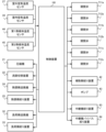
- FIG. 4 is a functional block diagram showing the refrigeration cycle device 1 according to the first embodiment.
- the control device 100 is connected to the compressor 21, the flow path switching device 22, the heat source side blower 24, the heat source side throttle device 25, the load side blower 32, the load side throttle device 33, the first bypass valve 51, the auxiliary side throttle device 42, and the pump 43 so that they can communicate wirelessly or by wire.
- the control device 100 controls the connection direction of the flow path switching device 22 to switch the operation mode.
- the control device 100 controls the rotation speed of the compressor 21, the rotation speed of the heat source side blower 24, the opening degree of the heat source side throttle device 25, the rotation speed of the load side blower 32, the opening degree of the load side throttle device 33, the opening degree of the auxiliary side throttle device 42, and the rotation speed of the pump 43 so that the temperature of the indoor air measured by the indoor air temperature sensor 34 becomes the temperature set by the user.
- the control device 100 also controls the opening of the auxiliary side throttling device 42 during heating operation so that the refrigerant flowing out of the heat medium heat exchanger 41 becomes a superheated gas.
- the control device 100 controls the opening of the auxiliary side throttling device 42 so that the measurement results of a temperature sensor (not shown) and a pressure sensor (not shown) provided on the outflow side of the heat medium heat exchanger 41 reach target values, for example. This ensures that the refrigerant drawn into the compressor 21 is in a gas state.
- the control device 100 controls the pump 43 so that the heat medium circulation amount becomes a first flow rate.
- the control device 100 controls the pump 43 so that the heat medium circulation amount becomes a second flow rate that is greater than the first flow rate.
- the threshold temperature is the temperature at which the heat medium freezes, and is, for example, 0°C. In this way, when the heat medium is lower than the threshold temperature, the heat medium can be prevented from freezing by increasing the heat medium circulation amount.
- the heat medium temperature compared with the threshold temperature may not be the temperature measured by the first heat medium temperature sensor 44, but may be the temperature of the heat medium flowing downstream of the heat medium heat exchanger 41 measured by the second heat medium temperature sensor 45. It may also be the average value of the temperatures of the heat medium flowing upstream and downstream of the heat medium heat exchanger 41.
- the control device 100 limits the range of the rotation speed of the heat source side blower 24 based on the comparison result between the heat medium temperature and the outdoor air temperature. Specifically, when the heat medium temperature is lower than the outdoor air temperature during cooling operation, the control device 100 controls the rotation speed of the heat source side blower 24 to within a first range. Similarly, when the heat medium temperature is higher than the outdoor air temperature during heating operation, the control device 100 controls the rotation speed of the heat source side blower 24 to within the first range.
- the first range is a range of rotation speeds lower than the rotation speed during rated operation.
- the rotation speed during rated operation is the maximum rotation speed at which the heat source side blower 24 can operate.
- the maximum rotation speed within the first range is, for example, 70% of the rotation speed during rated operation.
- the first range also includes the case where the rotation speed is 0, and when the rotation speed of the heat source side blower 24 is controlled to a rotation speed within the first range, the heat source side blower 24 may stop.
- the control device 100 limits the rotation speed of the heat source side blower 24 to a speed lower than the maximum rotation speed, and adjusts it to the minimum rotation speed at which the indoor air temperature can reach the set temperature. In other words, the control device 100 limits the rotation speed of the heat source side blower 24 to a speed lower than the maximum rotation speed, and adjusts it to the minimum rotation speed at which the heat exchange amount in the heat source side heat exchanger 23 and the heat medium heat exchanger 41 and the indoor load are balanced. The same applies when the heat medium temperature is higher than the outdoor air temperature during heating operation.
- the control device 100 may stop the heat source side blower 24 if the amount of heat exchange in the heat medium heat exchanger 41 is balanced with the indoor load without heat exchange by the heat source side heat exchanger 23. For example, when the rotation speed of the heat source side blower 24 is at a minimum, the control device 100 may stop the heat source side blower 24 if it determines that the amount of heat exchange in the heat source side heat exchanger 23 and the heat medium heat exchanger 41 is excessive compared to the indoor load.
- control device 100 may block the flow of refrigerant to the heat medium heat exchanger 41 when it is determined that the heat medium heat exchanger 41 does not function effectively as a condenser in cooling operation or as an evaporator in heating operation. Specifically, the control device determines that the heat medium heat exchanger does not function effectively as a condenser when the heat medium temperature is equal to or higher than the temperature of the outdoor air during cooling operation. Similarly, the control device determines that the heat medium heat exchanger does not function effectively as an evaporator when the heat medium temperature is equal to or lower than the temperature of the outdoor air during heating operation.
- control device 100 blocks the flow of refrigerant to the heat medium heat exchanger 41 by opening the first bypass valve 51 and closing the auxiliary side throttling device 42.
- the refrigeration cycle device 1 functions in the same way as a refrigeration cycle device without an auxiliary heat source unit 4, so the control device 100 controls the rotation speed of the heat source side blower 24 in the same way as a refrigeration cycle device without an auxiliary heat source unit 4.
- the control device 100 controls the rotation speed of the heat source side blower 24 to within a second range, which is a range of rotation speeds that includes the rotation speed during rated operation.
- the control device 100 performs cooling operation by switching the flow path switching device 22 so that the discharge side of the compressor 21 and the heat source side heat exchanger 23 are connected. At this time, the refrigerant sucked into the compressor 21 is compressed and discharged in a high-temperature, high-pressure gas state.
- the high-temperature, high-pressure gas state refrigerant discharged from the compressor 21 passes through the flow path switching device 22 and flows into the heat source side heat exchanger 23 acting as a condenser.
- the refrigerant that flows into the heat source side heat exchanger 23 is heat exchanged with the outdoor air sent by the heat source side blower 24 and condensed, becoming a high-temperature, high-pressure gas-liquid two-phase state.
- the high-temperature, high-pressure gas-liquid two-phase refrigerant flows into the heat medium heat exchanger 41 acting as a condenser.
- the refrigerant that flows into the heat medium heat exchanger 41 is heat exchanged with the heat medium and condensed, becoming a high-pressure liquid state.
- the high-pressure liquid refrigerant flows into the load-side throttle device 33, where it is decompressed and expanded to become a low-temperature, low-pressure, two-phase gas-liquid refrigerant.
- the two-phase gas-liquid refrigerant flows into the load-side heat exchanger 31, which acts as an evaporator.
- the refrigerant that flows into the load-side heat exchanger 31 exchanges heat with the indoor air sent by the load-side blower 32, causing the liquid phase to evaporate and become a gas. At that time, the indoor air is cooled and cooling is performed in the room.
- the low-temperature, low-pressure gas refrigerant that flows out of the load-side heat exchanger 31 passes through the flow switching device 22 and flows back into the compressor 21, where it is compressed and discharged in a high-temperature, high-pressure gas state. This cycle is repeated during the cooling operation of the refrigeration cycle device 1.
- FIG. 5 is a refrigerant circuit diagram showing the flow of refrigerant during heating operation of the refrigeration cycle device 1 according to the first embodiment.
- the control device 100 performs heating operation by switching the flow path switching device 22 so that the suction side of the compressor 21 and the heat source side heat exchanger 23 are connected. At this time, the refrigerant sucked into the compressor 21 is compressed and discharged in a high-temperature, high-pressure gas state.
- the high-temperature, high-pressure gas state refrigerant discharged from the compressor 21 passes through the flow path switching device 22 and flows into the load side heat exchanger 31 acting as a condenser.
- the refrigerant that flows into the load side heat exchanger 31 exchanges heat with the indoor air sent by the load side blower 32, condenses, and becomes a low-temperature liquid state. At this time, the indoor air is warmed, and heating is performed in the room.
- the low-temperature, high-pressure liquid refrigerant is decompressed by the load-side throttle device 33 and the auxiliary-side throttle device 42 to become a low-temperature, low-pressure, two-phase gas-liquid refrigerant.
- the low-temperature, low-pressure, two-phase gas-liquid refrigerant flows into the heat medium heat exchanger 41, which acts as an evaporator.
- the low-temperature, low-pressure, two-phase gas-liquid refrigerant that flows into the heat medium heat exchanger 41 exchanges heat with the heat medium, evaporating the liquid phase and becoming a superheated gas state.
- the superheated gas refrigerant that flows out of the heat medium heat exchanger 41 flows into the heat source-side heat exchanger 23, which acts as an evaporator.
- the superheated gas refrigerant that flows into the heat source-side heat exchanger 23 exchanges heat with the outdoor air supplied by the heat source-side blower 24, increasing the degree of superheat.
- the superheated gas refrigerant that flows out of the heat source-side heat exchanger 23 passes through the flow switching device 22, flows back into the compressor 21, is compressed, and is discharged in a high-temperature, high-pressure gas state. This cycle is repeated during heating operation of the refrigeration cycle device 1.
- FIG. 6 is a flowchart showing a method for controlling the rotation speed of the heat source side blower 24 according to the first embodiment.
- the control device 100 determines whether the operation mode is cooling operation (step S1). If the operation mode is cooling operation (step S1: YES), the control device 100 determines whether the heat medium temperature is lower than the outdoor air temperature (step S2). If the heat medium temperature is lower than the outdoor air temperature (step S2: YES), the control device 100 controls the rotation speed of the heat source side blower 24 to a rotation speed within a first range (step S3). If the heat medium temperature is equal to or higher than the outdoor air temperature (step S2: NO), the control device 100 controls the rotation speed of the heat source side blower 24 to a rotation speed within a second range (step S4).
- step S5 determines whether the heat medium temperature is higher than the outdoor air temperature (step S5). If the heat medium temperature is higher than the outdoor air temperature (step S5: YES), the control device 100 controls the rotation speed of the heat source side blower 24 to a rotation speed within a first range (step S6). If the heat medium temperature is equal to or lower than the outdoor air temperature (step S5: NO), the control device 100 controls the rotation speed of the heat source side blower 24 to a rotation speed within a second range (step S7).
- the refrigeration cycle apparatus 1 of the first embodiment when the heat medium heat exchanger 41 is functioning effectively, the rotation speed of the heat source side blower 24 is controlled to a rotation speed within a first range, which is a range of rotation speeds lower than the rotation speed during rated operation. Therefore, the refrigeration cycle apparatus 1 can suppress the power consumption related to the operation of the heat source side blower 24 and improve the energy saving performance.
- the evaporation temperature rises by controlling the rotation speed of the heat source side blower 24 to within a first range, which is a range of rotation speeds lower than the rotation speed during rated operation, and therefore it is possible to secure heating capacity.
- Fig. 7 is a refrigerant circuit diagram showing the flow of refrigerant during heating operation of the refrigeration cycle apparatus 1A according to embodiment 2.
- the refrigeration cycle apparatus 1A of embodiment 2 differs from the refrigeration cycle apparatus 1A of embodiment 1 in that it has a second bypass pipe 502 and a second bypass valve 53.
- the following mainly describes the differences from embodiment 1, and a description of the commonalities will be omitted.
- the heat source unit 2A has a second bypass pipe 502 and a second bypass valve 53.
- the second bypass pipe 502 is a pipe that connects the suction side of the compressor 21 and the downstream side of the heat medium heat exchanger 41 based on the flow of refrigerant during heating operation.
- the second bypass valve 53 is provided in the second bypass pipe 502, and switches between an open state that allows the flow of refrigerant and a closed state that blocks the flow of refrigerant.
- FIG. 8 is a functional block diagram showing a refrigeration cycle apparatus 1A according to the second embodiment.
- the control device 100 is communicatively connected to the second bypass valve 53 by wire or wirelessly, and controls the open/close state of the second bypass valve 53. Specifically, the control device 100 opens the second bypass valve 53 during heating operation, and closes the second bypass valve 53 during cooling operation.
- the control device 100 performs the heating operation by switching the flow path switching device 22 so that the suction side of the compressor 21 and the heat source side heat exchanger 23 are connected.
- the control device 100 also opens the second bypass valve 53.
- a part of the refrigerant in the superheated gas state that flows out of the heat medium heat exchanger 41 flows into the heat source side heat exchanger 23, and the remaining part flows into the second bypass piping 502.
- the refrigerant that flows into the heat source side heat exchanger 23 exchanges heat with the outdoor air supplied by the heat source side blower 24, and the degree of superheat increases.
- the refrigerant in the superheated gas state that flows out of the heat source side heat exchanger 23 passes through the flow path switching device 22 and merges with the refrigerant that passed through the second bypass piping 502.
- the refrigerant in the superheated gas state then passes through the accumulator 26 and flows back into the compressor 21, where it is compressed and discharged in a high-temperature, high-pressure gas state. This cycle is repeated during heating operation of the refrigeration cycle device 1A.
- the refrigeration cycle apparatus 1A of the second embodiment when the heat medium heat exchanger 41 is functioning effectively, the rotation speed of the heat source side blower 24 is controlled to a rotation speed within a first range, which is a range of rotation speeds lower than the rotation speed during rated operation. Therefore, the refrigeration cycle apparatus 1A can suppress the power consumption related to the operation of the heat source side blower 24 and improve the energy saving performance.
- the refrigeration cycle apparatus 1A of the second embodiment can reduce the flow rate of the refrigerant passing through the heat source side heat exchanger 23 more than the refrigeration cycle apparatus 1A of the first embodiment, and can reduce the rotation speed of the heat source side blower 24. Therefore, the refrigeration cycle apparatus 1A of the second embodiment can further improve the energy saving performance.
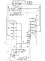
- FIG. 9 is a refrigerant circuit diagram showing the flow of refrigerant during cooling operation of the refrigeration cycle apparatus 1B according to embodiment 3.
- the refrigeration cycle apparatus 1B of embodiment 3 differs from the refrigeration cycle apparatus 1B of embodiment 1 mainly in that it has a relay unit 6.
- the following description will focus on the differences from embodiment 1, and will omit a description of the commonalities.
- the refrigeration cycle device 1B is connected between the heat source device 2B and the load device 3 and auxiliary heat source device 4, and is equipped with a relay device 6, which is a flow distribution unit that distributes the refrigerant into multiple flow paths.
- the heat source unit 2B and the relay unit 6 are connected by a high-pressure main pipe 801 and a low-pressure main pipe 802 through which the refrigerant flows.
- the high-pressure main pipe 801 is a pipe through which a high-pressure refrigerant flows
- the low-pressure main pipe 802 is a pipe through which a low-pressure refrigerant flows.
- the relay unit 6 and the load device 3 are connected by branch pipes 803a and 804a through which the refrigerant flows.
- the relay unit 6 and the load device 3 are connected by branch pipes 803b and 804b through which the refrigerant flows.
- the relay unit 6 and the auxiliary heat source unit 4 are connected by branch pipes 803c and 804c through which the refrigerant flows.
- the load devices 3a and 3b and the auxiliary heat source unit 4 are connected in parallel to the relay unit 6.
- the heat source unit 2B has a compressor 21, a flow path switching device 22, a heat source side heat exchanger 23, a heat source side blower 24, a heat source side throttle device 25, an accumulator 26, and check valves 28a to 28d.
- Check valves 28a to 28d allow refrigerant to flow only in a specified direction.
- Check valve 28a allows refrigerant to flow only from the relay 6 to the flow path switching device 22.
- Check valve 28b allows refrigerant to flow only from the flow path switching device 22 to the relay 6.
- Check valve 28c allows refrigerant to flow only from the relay 6 to the heat source side heat exchanger 23.
- Check valve 28d allows refrigerant to flow only from the heat source side heat exchanger 23 to the relay 6.
- the relay unit 6 has a first refrigerant heat exchanger 61, a second refrigerant heat exchanger 62, a relay unit throttling device 63, a relay unit bypass throttling device 64, on-off valves 711a-711c and 712a-712c, and check valves 721a-721c and 722a-722c.
- the first refrigerant heat exchanger 61 and the second refrigerant heat exchanger 62 are, for example, double-tube, plate, or shell-and-tube heat exchangers.
- the first refrigerant heat exchanger 61 and the second refrigerant heat exchanger 62 exchange heat between the refrigerants.
- the repeater throttle device 63 and the repeater bypass throttle device 64 are solenoid valves whose opening degree is variably controlled.
- the repeater throttle device 63 is connected in series with the first refrigerant heat exchanger 61 and adjusts the flow rate of the refrigerant flowing through the first refrigerant heat exchanger 61.
- the repeater bypass throttle device 64 is provided in the repeater bypass piping 503 that connects the downstream side of the second refrigerant heat exchanger 62 and the downstream side of the on-off valves 712a to 712c and circulates a portion of the refrigerant flowing between the load device 3 and the auxiliary heat source device 4 to the heat source device 2B.
- the repeater bypass throttle device 64 is connected in parallel with the check valves 722a to 722c and adjusts the flow rate of the heat medium flowing downstream of the on-off valves 712a to 712c via the second refrigerant heat exchanger 62 and the first refrigerant heat exchanger 61.
- the on-off valve 711a is a valve that can be selectively switched between an open state that allows the flow of refrigerant between the high-pressure main pipe 801 and the branch pipe 803a, and a closed state that blocks the flow of refrigerant.
- the on-off valve 711b is a valve that can be selectively switched between an open state that allows the flow of refrigerant between the high-pressure main pipe 801 and the branch pipe 803b, and a closed state that blocks the flow of refrigerant.
- the on-off valve 711c is a valve that can be selectively switched between an open state that allows the flow of refrigerant between the high-pressure main pipe 801 and the branch pipe 803c, and a closed state that blocks the flow of refrigerant.
- the on-off valve 712a is a valve that can be selectively switched between an open state that allows refrigerant to flow between the low-pressure main pipe 802 and the branch pipe 803a, and a closed state that blocks the flow of refrigerant.
- the on-off valve 712b is a valve that can be selectively switched between an open state that allows refrigerant to flow between the low-pressure main pipe 802 and the branch pipe 803b, and a closed state that blocks the flow of refrigerant.
- the on-off valve 712c is a valve that can be selectively switched between an open state that allows refrigerant to flow between the low-pressure main pipe 802 and the branch pipe 803c, and a closed state that blocks the flow of refrigerant.
- Check valves 721a-721c and 722a-722c allow refrigerant to flow only in a specified direction.
- Check valve 721a allows refrigerant to flow only in the direction from load device 3a to relay unit 6.
- Check valve 721b allows refrigerant to flow only in the direction from load device 3b to relay unit 6.
- Check valve 721c allows refrigerant to flow only in the direction from auxiliary heat source unit 4 to relay unit 6.
- Check valve 722a allows refrigerant to flow only in the direction from relay unit 6 to load device 3a.
- Check valve 722b allows refrigerant to flow only in the direction from relay unit 6 to load device 3b.
- Check valve 722c allows refrigerant to flow only in the direction from relay unit 6 to auxiliary heat source unit 4.
- FIG 10 is a functional block diagram showing a refrigeration cycle apparatus 1B relating to embodiment 3.
- the control device 100 is connected to the compressor 21, the flow path switching device 22, the heat source side blower 24, the heat source side throttling device 25, the load side blower 32, the load side throttling device 33, the on-off valves 711a-711c and 712a-712c, the auxiliary side throttling device 42, the pump 43, the repeater throttling device 63, and the repeater bypass throttling device 64 so as to be able to communicate wirelessly or by wire.
- the control device 100 controls the connection direction of the flow path switching device 22, the open/closed state of the on-off valves 711a-711c and 712a-712c, and the open/closed state of the repeater throttling device 63 to switch the operation mode.
- the control device 100 controls the rotation speed of the compressor 21, the rotation speed of the heat source side blower 24, the opening degree of the heat source side throttling device 25, the rotation speed of the load side blower 32, the opening degree of the load side throttling device 33, the repeater throttling device 63, the repeater bypass throttling device 64, the opening degree of the auxiliary side throttling device 42, and the rotation speed of the pump 43 so that the indoor air temperature measured by the indoor air temperature sensor 34 becomes the temperature set by the user.
- the control device 100 controls the opening degree of the repeater bypass throttling device 64 so that the refrigerant in the liquid state or two-phase state flows through the repeater 6 bypass piping during heating operation.
- control device 100 controls the rotation speed of the heat source side blower 24 to within the first range described in embodiment 1.
- control device 100 controls the rotation speed of the heat source side blower 24 to within the first range.
- control device 100 may block the flow of refrigerant to the heat medium heat exchanger 41 when it is determined that the heat medium heat exchanger 41 does not function effectively as a condenser in cooling operation or as an evaporator in heating operation. Specifically, the control device determines that the heat medium heat exchanger does not function effectively as a condenser when the heat medium temperature is equal to or higher than the outdoor air temperature during cooling operation. Similarly, the control device determines that the heat medium heat exchanger does not function effectively as an evaporator when the heat medium temperature is equal to or lower than the outdoor air temperature during heating operation. The control device 100 also blocks the flow of refrigerant to the heat medium heat exchanger 41 by closing the auxiliary side throttling device 42.
- the relay bypass throttling device 64 is further opened to ensure a refrigerant flow path from the relay unit 6 to the heat source unit 2.
- the refrigeration cycle device 1B functions in the same way as a refrigeration cycle device without an auxiliary heat source unit 4, so the control device 100 controls the rotation speed of the heat source side blower 24 to within a second range, which is a range of rotation speeds that includes the rotation speed during rated operation.
- the control device 100 performs cooling operation by switching the flow path switching device 22 so that the discharge side of the compressor 21 and the heat source side heat exchanger 23 are connected.
- the control device 100 also opens the on-off valves 712a, 712b, and 711c, and closes the on-off valves 711a, 711b, and 712c.
- the control device 100 opens the relay bypass throttle device 64. At this time, the high-temperature, high-pressure gas refrigerant discharged from the compressor 21 flows into the heat source side heat exchanger 23 through the flow path switching device 22.
- the refrigerant that flows into the heat source side heat exchanger 23 exchanges heat with the air supplied by the heat source side blower 24, condenses, and liquefies, becoming a medium-temperature, high-pressure two-phase refrigerant.
- the medium-temperature, high-pressure two-phase refrigerant that flows out of the heat source side heat exchanger 23 passes through the heat source side throttle device 25, the check valve 28d, and the high-pressure main pipe 801 and flows into the relay unit 6.
- the medium-temperature, high-pressure two-phase refrigerant that flows into the relay unit 6 is separated into a gas-rich refrigerant and a liquid-rich refrigerant.
- the gas-rich refrigerant flows into the auxiliary heat source unit 4 through the on-off valve 711c, and is condensed and liquefied by heat exchange with the heat medium in the heat medium heat exchanger 41 that operates as a condenser, becoming a low-temperature, high-pressure liquid refrigerant.
- the low-temperature, high-pressure liquid refrigerant that flows out of the heat medium heat exchanger 41 is depressurized in the auxiliary side throttling device 42 to become a low-temperature, medium-pressure liquid or two-phase refrigerant, and then passes through the branch pipe 804c and the check valve 721c to merge with the liquid-rich refrigerant that flows out of the relay unit throttling device 63.
- the liquid-rich refrigerant is cooled and condensed in the first refrigerant heat exchanger 61, becoming a low-temperature, high-pressure liquid.
- the low-temperature, high-pressure liquid is decompressed in the relay throttling device 63, becoming a low-temperature, medium-pressure liquid or two-phase refrigerant, and then merges with the condensed and liquefied refrigerant in the heat medium heat exchanger 41.
- the low-temperature, medium-pressure liquid or two-phase refrigerant is then cooled and condensed in the second refrigerant heat exchanger 62, becoming a low-temperature, medium-pressure liquid refrigerant.
- the low-temperature, medium-pressure liquid refrigerant flows into the load device 3 through the check valves 722a and 722b and the branch pipes 804a and 804b, and is reduced in pressure by the load-side throttle device 33 to become a low-temperature, low-pressure two-phase refrigerant.
- the low-temperature, low-pressure two-phase refrigerant then flows into the load-side heat exchanger 31, where it exchanges heat with the indoor air in the load-side heat exchanger 31, which operates as an evaporator, and evaporates to become a high-temperature, low-pressure gas refrigerant.
- the high-temperature, low-pressure gas refrigerant that flows out of the load-side heat exchanger 31 flows into the heat source unit 2B through the branch pipes 803a and 803b, the opening/closing valves 712a and 712b, and the low-pressure main pipe 802.
- the high-temperature, low-pressure gas refrigerant that flows into the heat source unit 2B passes through the check valve 28a, the flow path switching device 22, and the accumulator 26, and then returns to the compressor 21.
- FIG. 11 is a refrigerant circuit diagram showing the flow of refrigerant during heating operation of the refrigeration cycle device 1B according to the third embodiment.
- the control device 100 performs heating operation by switching the flow path switching device 22 so that the suction side of the compressor 21 and the heat source side heat exchanger 23 are connected.
- the control device 100 also opens the on-off valves 711a, 711b, and 712c, closes the on-off valves 712a, 712b, and 711c, and closes the relay throttle device 63.
- the high-temperature, high-pressure gas refrigerant discharged from the compressor 21 flows into the relay 6 through the flow path switching device 22, the check valve 28b, and the high-pressure main pipe 801.
- the gas refrigerant that flows into the relay 6 flows into the load device 3 through the on-off valves 711a and 711b and the branch pipes 803a and 803b.
- the high-temperature, high-pressure gas refrigerant that flows into the load device 3 flows into the load-side heat exchanger 31, where it exchanges heat with the indoor air in the load-side heat exchanger 31 that operates as a condenser, and is condensed and liquefied to become a low-temperature, high-pressure liquid refrigerant.
- the low-temperature, high-pressure liquid refrigerant that flows out of the load-side exchanger is depressurized in the load-side throttle device 33 to become a low-temperature, medium-pressure liquid or two-phase refrigerant.
- the low-temperature, medium-pressure liquid or two-phase refrigerant then passes through the branch pipes 804a and 804b and the check valves 721a and 722b, and is cooled in the second inter-refrigerant heat exchanger 62, where it is condensed and liquefied to become a low-temperature, medium-pressure liquid refrigerant.
- a portion of the low-temperature, medium-pressure liquid refrigerant is bypassed, and the remaining portion is depressurized in the relay bypass throttle device 64 to become a low-temperature, low-pressure two-phase refrigerant, and is then heated in the second inter-refrigerant heat exchanger 62 and the first inter-refrigerant heat exchanger 61.
- the bypassed low-temperature, medium-pressure liquid refrigerant flows into the auxiliary heat source unit 4 through the check valve 722c and the branch pipe 804c.
- the low-temperature, medium-pressure liquid refrigerant that flows into the auxiliary heat source unit 4 is depressurized by the auxiliary side throttle device 42 to become a low-temperature, low-pressure two-phase refrigerant.
- the low-temperature, low-pressure two-phase refrigerant then flows into the heat medium heat exchanger 41, where it exchanges heat with the heat medium in the heat medium heat exchanger 41 operating as an evaporator, evaporating and vaporizing, becoming a high-temperature, low-pressure gas refrigerant.
- the high-temperature, low-pressure gas refrigerant then flows into the relay unit 6 through the branch pipe 803c.
- the low-temperature, low-pressure two-phase refrigerant heated in the second refrigerant heat exchanger 62 and the first refrigerant heat exchanger 61 merges with the high-temperature, low-pressure gas refrigerant that has passed through the on-off valve 712c, and then flows into the heat source unit 2B through the low-pressure main pipe 802.
- the low-temperature, low-pressure two-phase refrigerant that flows into the heat source unit 2B passes through the check valve 28c and the heat source side throttle device 25 and flows into the heat source side heat exchanger 23.
- the refrigerant that flows into the heat source side heat exchanger 23 exchanges heat with the air supplied by the heat source side blower 24 and evaporates, becoming a high-temperature, low-pressure gas or two-phase refrigerant.
- the high-temperature, low-pressure gas or two-phase refrigerant that flows out of the heat source side heat exchanger 23 passes through the flow switching device 22 and the accumulator 26 and returns to the compressor 21.
- the refrigeration cycle apparatus 1B of the third embodiment when the heat medium heat exchanger 41 is functioning effectively, the rotation speed of the heat source side blower 24 is controlled to a rotation speed within a first range, which is a range of rotation speeds lower than the rotation speed during rated operation. Therefore, the refrigeration cycle apparatus 1B can suppress the power consumption related to the operation of the heat source side blower 24 and improve the energy saving performance.
- FIG. 12 is a refrigerant circuit diagram showing the flow of refrigerant during cooling operation of a refrigeration cycle apparatus 1C according to embodiment 4.
- the refrigeration cycle apparatus 1C according to embodiment 3 differs from embodiment 2 in the configurations of a heat source unit 2C and a relay unit 6A, and in the configuration of the refrigerant piping connecting the heat source unit 2C and the relay unit 6A.
- the following mainly describes the differences from embodiment 3, and a description of the commonalities will be omitted.
- the heat source unit 2C and the relay unit 6A are connected by a high-pressure gas pipe 805 through which a refrigerant flows.
- the high-pressure gas pipe 805 is a pipe through which a high-pressure gas refrigerant flows
- the low-pressure gas pipe 806 is a pipe through which a low-pressure gas refrigerant flows
- the liquid pipe 807 is a pipe through which a liquid refrigerant flows.
- the heat source unit 2C has a compressor 21, flow path switching devices 22 and 22b, a heat source side heat exchanger 23, a heat source side blower 24, a heat source side throttle device 25, and an accumulator 26.
- the flow path switching devices 22a and 22b switch between cooling operation, in which the heat source side heat exchanger 23 functions as a condenser, and heating operation, in which the heat source side heat exchanger 23 functions as an evaporator.
- the flow path switching devices 22 and 22b are, for example, four-way valves, and are controlled by the control device 100.
- the flow path switching device 22a connects the discharge side of the compressor 21 to the relay unit 6 during cooling operation, and connects the discharge side of the compressor 21 to the relay unit 6 during heating operation.
- the flow path switching device 22b connects the discharge side of the compressor 21 to the heat source side heat exchanger 23 during cooling operation, and connects the flow path switching device 22 to the suction side of the compressor 21 to the heat source side heat exchanger 23 during heating operation.
- the relay unit 6A has a first refrigerant heat exchanger 61, a second refrigerant heat exchanger 62, a relay unit throttling device 63, a relay unit bypass throttling device 64, on-off valves 711a-711c and 712a-712c, and check valves 721a-721c and 722a-722c.
- the on-off valve 711a is a valve that can be selectively switched between an open state that allows the flow of refrigerant between the low-pressure gas pipe 806 and the branch pipe 803a, and a closed state that blocks the flow of refrigerant.
- the on-off valve 711b is a valve that can be selectively switched between an open state that allows the flow of refrigerant between the low-pressure gas pipe 806 and the branch pipe 803b, and a closed state that blocks the flow of refrigerant.
- the on-off valve 711c is a valve that can be selectively switched between an open state that allows the flow of refrigerant between the low-pressure gas pipe 806 and the branch pipe 803c, and a closed state that blocks the flow of refrigerant.
- the on-off valve 712a is a valve that can be selectively switched between an open state that allows the flow of refrigerant between the high-pressure gas pipe 805 and the branch pipe 803a, and a closed state that blocks the flow of refrigerant.
- the on-off valve 712b is a valve that can be selectively switched between an open state that allows the flow of refrigerant between the high-pressure gas pipe 805 and the branch pipe 803b, and a closed state that blocks the flow of refrigerant.
- the on-off valve 712c is a valve that can be selectively switched between an open state that allows the flow of refrigerant between the high-pressure gas pipe 805 and the branch pipe 803c, and a closed state that blocks the flow of refrigerant.
- FIG. 13 is a functional block diagram showing a refrigeration cycle apparatus 1C according to embodiment 4.
- the control device 100 is connected to the compressor 21, the flow path switching devices 22a and 22b, the heat source side blower 24, the heat source side throttling device 25, the load side blower 32, the load side throttling device 33, the on-off valves 711a-711c and 712a-712c, the auxiliary side throttling device 42, the pump 43, the repeater throttling device 63, and the repeater bypass throttling device 64 wirelessly or by wire so as to be able to communicate with them.
- the control device 100 controls the connection direction of the flow path switching devices 22a and 22b and the open/closed state of the on-off valves 711a-711c and 712a-712c to switch the operation mode.
- control device 100 controls the rotation speed of the heat source side blower 24 to within the first range described in embodiment 1.
- control device 100 controls the rotation speed of the heat source side blower 24 to within the first range.
- control device 100 may block the flow of refrigerant to the heat medium heat exchanger 41 when it is determined that the heat medium heat exchanger 41 does not function effectively as a condenser in cooling operation or as an evaporator in heating operation. Specifically, the control device determines that the heat medium heat exchanger does not function effectively as a condenser when the heat medium temperature is equal to or higher than the temperature of the outdoor air during cooling operation. Similarly, the control device determines that the heat medium heat exchanger does not function effectively as an evaporator when the heat medium temperature is equal to or lower than the temperature of the outdoor air during heating operation. In addition, the control device 100 blocks the flow of refrigerant to the heat medium heat exchanger 41 by closing the auxiliary side throttle device 42.
- the refrigeration cycle device 1C functions in the same way as a refrigeration cycle device without an auxiliary heat source unit 4, so the control device 100 controls the rotation speed of the heat source side blower 24 to within a second range that is a range of rotation speeds that includes the rotation speed during rated operation.
- the control device 100 performs cooling operation by switching the flow path switching device 22a to a direction that connects the discharge side of the compressor 21 to the relay unit 6, and switching the flow path switching device 22b to a direction that connects the discharge side of the compressor 21 to the heat source side heat exchanger 23.
- the control device 100 also opens the on-off valves 711a, 711b, and 712c, and closes the on-off valves 712a, 712b, and 711c.
- part of the high-temperature, high-pressure gas refrigerant discharged from the compressor 21 flows into the relay unit 6A through the high-pressure gas pipe 805, and the remainder flows into the heat source side heat exchanger 23 through the flow path switching device 22b.
- the refrigerant that flows into the relay unit 6A flows into the auxiliary heat source unit 4 through the on-off valve 712c and the branch pipe 803c, and is condensed and liquefied by heat exchange with the heat medium in the heat medium heat exchanger 41 that operates as a condenser, becoming a low-temperature, high-pressure liquid refrigerant.
- the low-temperature, high-pressure liquid refrigerant then flows into the relay unit 6A through the auxiliary side throttle device 42, the branch pipe 804c, and the check valve 721c.
- the refrigerant that flows into the heat source side heat exchanger 23 exchanges heat with the air supplied by the heat source side blower 24, and a portion of it condenses and liquefies, becoming a low-temperature, high-pressure liquid refrigerant.
- the low-temperature, high-pressure liquid refrigerant that flows out of the heat source side heat exchanger 23 flows into the relay unit 6A through the heat source side throttle device 25 and the liquid piping 807.
- the low-temperature, high-pressure liquid refrigerant that flows into the relay unit 6A passes through the first inter-refrigerant heat exchanger 61, merges with the low-temperature, high-pressure liquid refrigerant that has passed through the check valve 721c, and then passes through the second inter-refrigerant heat exchanger 62.
- the low-temperature, high-pressure liquid refrigerant flows into the load device 3 through the check valves 722a and 722b and the branch piping 804a and 804b.
- the low-temperature, high-pressure liquid refrigerant that flows into the load device 3 is depressurized by the flow control valve to become a low-temperature, low-pressure two-phase refrigerant.
- the low-temperature, low-pressure two-phase refrigerant then flows into the load-side heat exchanger 31, where it exchanges heat with the indoor air in the load-side heat exchanger 31, which operates as an evaporator, and evaporates to become a high-temperature, low-pressure gas refrigerant.
- the high-temperature, low-pressure gas refrigerant that flows out of the load-side heat exchanger 31 flows into the relay unit 6A through the branch pipes 803a and 803b and the on-off valves 711a and 711b, and further flows into the heat source unit 2C through the low-pressure gas pipe 806.
- the high-temperature, low-pressure gas refrigerant that flows into the heat source unit 2C passes through the accumulator 26 and returns to the compressor 21.
- FIG. 14 is a refrigerant circuit diagram showing the flow of refrigerant during heating operation of the refrigeration cycle device 1C according to embodiment 4.
- the control device 100 performs heating operation by switching the flow path switching device 22a to a direction that connects the discharge side of the compressor 21 to the relay device 6, and switching the flow path switching device 22b to a direction that connects the suction side of the compressor 21 to the heat source side heat exchanger 23.
- the control device 100 opens the on-off valves 712a, 712b, and 711c, and closes the on-off valves 711a, 711b, and 712c.
- the high-temperature, high-pressure gas refrigerant discharged from the compressor 21 flows into the relay device 6A through the high-pressure gas pipe 805.
- the high-temperature, high-pressure gas refrigerant that has flowed into the relay device 6A flows into the load device 3 through the on-off valves 712a and 712b and the branch pipes 803a and 803b.
- the high-temperature, high-pressure gas refrigerant that flows into the load device 3 flows into the load-side heat exchanger 31, where it exchanges heat with the indoor air in the load-side heat exchanger 31 that operates as a condenser, and condenses and liquefies to become a low-temperature, high-pressure liquid refrigerant.
- the low-temperature, high-pressure liquid refrigerant that flows out of the load-side heat exchanger 31 is depressurized in the load-side throttling device 33 to become a low-temperature, medium-pressure liquid or two-phase refrigerant.
- the low-temperature, medium-pressure liquid or two-phase refrigerant then passes through the branch pipes 804a and 804b and the check valves 721a and 721b.
- a portion of the low-temperature, medium-pressure liquid or two-phase refrigerant that has passed through the check valves 721a and 721b passes through the relay throttling device 63 and the first inter-refrigerant heat exchanger 61 to flow into the heat source unit 2C, and the remainder passes through the second inter-refrigerant heat exchanger 62, the check valve 722c, and the liquid pipe 807 to flow into the auxiliary heat source unit 4.
- the low-temperature, medium-pressure liquid or two-phase refrigerant that flows into the heat source unit 2C is depressurized by the heat source side throttle device 25 to become a low-temperature, low-pressure two-phase refrigerant.
- the low-temperature, low-pressure two-phase refrigerant then flows into the heat source side heat exchanger 23, where it exchanges heat with the air supplied by the heat source side blower 24 and evaporates, becoming a high-temperature, low-pressure gas or two-phase refrigerant.
- the low-temperature, medium-pressure liquid or two-phase refrigerant that flows into the auxiliary heat source unit 4 is depressurized by the auxiliary side throttle device 42 to become a low-temperature, low-pressure two-phase refrigerant.
- the low-temperature, low-pressure two-phase refrigerant then flows into the heat medium heat exchanger 41, where it exchanges heat with the heat medium in the heat medium heat exchanger 41, which operates as an evaporator, and evaporates to become a high-temperature, low-pressure gas refrigerant.
- the high-temperature, low-pressure gas refrigerant that flows out of the heat medium heat exchanger 41 flows into the heat source unit 2C through the branch pipe 803c, the on-off valve 711c, and the low-pressure gas pipe 806.
- the high-temperature, low-pressure gas or two-phase refrigerant merges with the high-temperature, low-pressure gas refrigerant that has passed through the flow path switching device 22b, passes through the accumulator 26, and returns to the compressor 21.
- FIG. 15 is a refrigerant circuit diagram showing the flow of refrigerant during heating operation of the refrigeration cycle device 1C according to the fourth embodiment. In this case, as shown in FIG. 15, the control device 100 closes the relay throttling device 63.
- the low-temperature, low-pressure two-phase refrigerant then flows into the heat medium heat exchanger 41, where it exchanges heat with the heat medium in the heat medium heat exchanger 41, which operates as an evaporator, and evaporates to become a high-temperature, low-pressure gas refrigerant.
- the high-temperature, low-pressure gas refrigerant that flows out of the heat medium heat exchanger 41 flows into the heat source unit 2C through the branch pipe 803c, the on-off valve 711c, and the low-pressure gas pipe 806.
- the high-temperature, low-pressure gas or two-phase refrigerant then flows through the accumulator 26 and returns to the compressor 21.
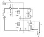
- FIG. 16 is a refrigerant circuit diagram showing a refrigeration cycle apparatus 1D according to a modified example.
- the heat source unit 2D and the load unit 3 are connected by a heat medium pipe 602
- the heat source unit 2D and the auxiliary heat source unit 4 are connected by a heat medium pipe 603.
- the heat source unit 2D has a compressor 21, a flow switching device 22, a heat source side heat exchanger 23, a first heat source side heat medium heat exchanger 71, a throttling device 72, a second heat source side heat medium heat exchanger 73, and a throttling device 74, and these are connected by piping to form a refrigerant circuit.
- the first heat source side heat medium heat exchanger 71 exchanges heat between the refrigerant flowing in the refrigerant circuit and a heat medium such as water flowing in the heat medium piping 602.
- the second heat source side heat medium heat exchanger 73 exchanges heat between the refrigerant flowing in the refrigerant circuit and a heat medium such as water flowing in the heat medium piping 602.
- the throttling devices 72 and 74 reduce the pressure of the refrigerant flowing in the refrigerant circuit to expand it.
- a heat medium such as water flows through the heat medium piping 602.
- the heat medium is pumped out by a pump 75 and circulates between the first heat source side heat medium heat exchanger 71 and the load side heat exchanger 31.
- a heat medium such as water flows through the heat medium piping 603.
- the heat medium is pumped out by a pump 76 and circulates between the second heat source side heat medium heat exchanger 73 and the heat medium heat exchanger 41.
- the heat source unit 2D supplies cold or hot heat to the load device 3 by performing heat exchange in the first heat source side heat medium heat exchanger 71.
- the auxiliary heat source unit 4 supplies cold or hot heat to the heat source unit 2D by performing heat exchange in the second heat source side heat medium heat exchanger 73.
- the rotation speed of the heat source side blower 24 is controlled in the same manner as in embodiment 1. Therefore, the refrigeration cycle device 1D can reduce the power consumption related to the operation of the heat source side blower 24 and improve energy saving performance.
Landscapes
- Engineering & Computer Science (AREA)
- Physics & Mathematics (AREA)
- Mechanical Engineering (AREA)
- Thermal Sciences (AREA)
- General Engineering & Computer Science (AREA)
- Compression-Type Refrigeration Machines With Reversible Cycles (AREA)
Abstract
Description
本開示は、冷凍サイクル装置に関するものである。 This disclosure relates to a refrigeration cycle device.
従来、空気調和機などの冷凍サイクル装置において、地中熱などの所謂再生可能エネルギーを利用することが提案されている(例えば、特許文献1)。特許文献1の空気調和機は、熱源機が有する熱交換器に加えて、再生可能エネルギーを有する熱源と冷媒との間で熱交換を行うための熱交換器を設けることで、総伝熱面積が増加している。特許文献1の空気調和機は、これによって空調能力の向上を図っている。
Conventionally, it has been proposed to utilize so-called renewable energy such as geothermal heat in refrigeration cycle devices such as air conditioners (for example, Patent Document 1). The air conditioner of
しかしながら、特許文献1では、総伝熱面積が増加したのにも関わらず、一部の機器は再生可能エネルギーを有する熱源がない場合と同様に制御されている。したがって、特許文献1の空気調和機においては、必要以上の能力での運転が行われ、無駄な電力が消費されている。
However, in
本開示は、上記のような課題を解決するためになされたもので、省エネルギー性能を向上させる冷凍サイクル装置を提供することを目的としている。 This disclosure has been made to solve the problems described above, and aims to provide a refrigeration cycle device that improves energy-saving performance.
本開示に係る冷凍サイクル装置は、冷媒を圧縮する圧縮機と、冷媒と室外空気との間で熱交換を行う熱源側熱交換器と、熱源側熱交換器に室外空気を供給する熱源側送風機と、を有する熱源機と、冷媒と加熱対象又は冷却対象である流体との間で熱交換を行う負荷側熱交換器を有する負荷装置と、室外空気と異なる再生可能エネルギーに由来した熱を有する熱媒体と冷媒との間で熱交換を行う熱媒体熱交換器を有する補助熱源機と、熱媒体の温度と室外空気の温度との比較結果に基づき、熱源側送風機の回転数を、定格運転時の回転数よりも小さい回転数の範囲である第1範囲内の回転数に制御する制御装置と、を備える。 The refrigeration cycle device according to the present disclosure includes a heat source unit having a compressor that compresses a refrigerant, a heat source side heat exchanger that exchanges heat between the refrigerant and outdoor air, and a heat source side blower that supplies outdoor air to the heat source side heat exchanger; a load unit having a load side heat exchanger that exchanges heat between the refrigerant and a fluid that is to be heated or cooled; an auxiliary heat source unit having a heat medium heat exchanger that exchanges heat between the refrigerant and a heat medium that has heat derived from a renewable energy different from the outdoor air; and a control device that controls the rotation speed of the heat source side blower to within a first range that is a range of rotation speeds lower than the rotation speed during rated operation based on the comparison result between the temperature of the heat medium and the temperature of the outdoor air.
本開示の冷凍サイクル装置によれば、熱源側送風機の回転数が、定格運転時の回転数よりも小さい回転数の範囲である第1範囲内の回転数に制御されている。このため、冷凍サイクル装置は、熱源側送風機の運転に係る電力の消費を抑制し、省エネルギー性能を向上させることができる。 According to the refrigeration cycle device disclosed herein, the rotation speed of the heat source side blower is controlled to within a first range, which is a range of rotation speeds lower than the rotation speed during rated operation. Therefore, the refrigeration cycle device can reduce the power consumption related to the operation of the heat source side blower and improve energy saving performance.
以下、図面に基づいて実施の形態について説明する。なお、各図において、同一の符号を付したものは、同一のまたはこれに相当するものであり、これは明細書の全文において共通している。また、明細書全文に示す構成要素の形態は、あくまで例示であってこれらの記載に限定されるものではない。さらに、以下の図面では各構成部材の大きさの関係が実際のものとは異なる場合がある。 Below, an embodiment will be described with reference to the drawings. In each drawing, the same reference numerals are used to denote the same or equivalent parts, and this is the same throughout the entire specification. Furthermore, the forms of the components shown in the entire specification are merely examples and are not limited to these descriptions. Furthermore, the size relationships between the components in the drawings may differ from the actual ones.
実施の形態1.
図1は、実施の形態1に係る冷凍サイクル装置1の冷房運転時の冷媒の流れを示す冷媒回路図である。実施の形態1の冷凍サイクル装置1は、室内の冷房及び暖房を行う空気調和機である。冷凍サイクル装置1は、熱源機2、負荷装置3a及び3b、並びに補助熱源機4を備える。熱源機2と負荷装置3a及び負荷装置3bとは、第1接続配管401によって接続されている。負荷装置3a及び負荷装置3bと補助熱源機4とは、第2接続配管402によって接続されている。補助熱源機4と熱源機2とは、第3接続配管403によって接続されている。
FIG. 1 is a refrigerant circuit diagram showing the flow of refrigerant during cooling operation of a
以下では、冷凍サイクル装置1が少なくとも運転モードとして冷房運転及び暖房運転を実行可能な空気調和機である場合を例にして説明するが、冷凍サイクル装置1は、収納物を冷却する冷蔵庫、冷凍庫、又は自動販売機であってもよい。また、冷凍サイクル装置1は、ショーケース等に設けられる冷凍装置であってもよい。更に、冷凍サイクル装置1は、温水を供給する給湯器、又は冷水を供給するチラーであってもよい。なお、冷凍サイクル装置1は、除湿運転等、冷房運転及び暖房運転以外の運転モードが実行可能であってもよい。
In the following, an example will be described in which the
熱源機2は、例えば室外に設けられた室外機である。熱源機2は、負荷装置3に温熱又は冷熱を供給する機器である。熱源機2は、圧縮機21、流路切替装置22、熱源側熱交換器23、熱源側送風機24、熱源側絞り装置25、アキュムレータ26、及び制御装置100を有している。
The
圧縮機21は、低圧のガス冷媒を吸入して圧縮し、高圧のガス冷媒として吐出する。圧縮機21としては、例えばレシプロ、ロータリー、スクロール又はスクリューなどの圧縮機21が用いられる。
The
流路切替装置22は、熱源側熱交換器23が凝縮器として機能する冷房運転と、熱源側熱交換器23が蒸発器として機能する暖房運転とを切り替える。流路切替装置22は、例えば四方弁であり、制御装置100によって制御される。流路切替装置22は、冷房運転時は圧縮機21から吐出される冷媒が熱源側熱交換器23に流入するよう切り替えられる。流路切替装置22は、暖房運転時は圧縮機21から吐出される冷媒が負荷装置3a及び3bに流入するよう切り替えられる。
The flow
熱源側熱交換器23は、例えばフィンチューブ式の熱交換器であり、円管又は扁平管の内部を流通する冷媒と、熱源側送風機24により供給される室外空気との熱交換を行う。熱源側熱交換器23は、暖房運転において蒸発器として機能し、冷房運転時において凝縮器として機能する。
The heat source
熱源側送風機24は、熱源側熱交換器23に室外空気を送る機器である。熱源側送風機24は、熱源側熱交換器23に隣接して配置される。熱源側送風機24から室外空気が送られることで、冷媒と室外空気との間の熱交換の効率が向上する。熱源側送風機24としては、プロペラファン、ラインフローファン(登録商標)、又は多翼遠心ファンが用いられる。
The heat
熱源側絞り装置25は、開度が調整可能な電子膨張弁である。熱源側絞り装置25は、熱源側熱交換器23に流入する冷媒又は熱源側熱交換器23から流出する冷媒を減圧して膨張させる。熱源側絞り装置25の開度は、制御装置100により制御される。
The heat source
アキュムレータ26は、運転状態に応じて余剰となった冷媒を貯留する。アキュムレータ26は、圧縮機21の吸入口及び流路切替装置22と接続されており、流路切替装置22を通って流入した冷媒をガス冷媒と液冷媒とに分離し、液冷媒を貯留し、ガス冷媒を圧縮機21に流出させる。なお、アキュムレータ26は必須の構成ではなく、省略してもよい。
The
制御装置100は、冷凍サイクル装置1が有する各機器を制御する。図2は、実施の形態1に係る制御装置100を示すハードウェア構成図である。制御装置100は、図2に示すように、ASIC(Application Specific Integrated Circuit)、又はFPGA(Field-Programmable Gate Array)等の処理回路101で構成される専用のハードウェアである。また、図3は、実施の形態1に係る制御装置100を示すハードウェア構成図である。制御装置100の機能がソフトウェアで実行される場合、図3に示すように、制御装置100をCPU等のプロセッサ102及びメモリ103で構成するようにしてもよい。図3は、プロセッサ102及びメモリ103が互いにバス104を介して通信可能に接続されることを示している。制御装置100の機能は、プロセッサ102がメモリ103に記憶されたブログラムを読み出して実行することにより実現される。メモリ103としては、不揮発性若しくは揮発性の半導体メモリ等、又は着脱可能な記録媒体が用いられる。制御装置100の機能についての説明は、後述する。
The
なお、図1では、制御装置100が熱源機2に設けられているが、制御装置100は、負荷装置3a又は3bに設けられてもよいし、熱源機2並びに負荷装置3a及び3bにそれぞれ個別の制御装置100を設け、互いに通信する構成としてもよい。また、熱源機2及び負荷装置3から離れた場所に制御装置100が設けられてもよい。
In FIG. 1, the
負荷装置3a及び3bは、例えば室内に設けられた室内機である。負荷装置3a及び3bは、熱源機2及び補助熱源機4から冷媒を介して冷熱又は温熱の供給を受け、室内の空調を行うものである。負荷装置3aは、負荷側熱交換器31a、負荷側送風機32、及び負荷側絞り装置33aを有している。負荷装置3bは、負荷側熱交換器31b、負荷側送風機32、及び負荷側絞り装置33bを有している。以下では、負荷装置3a及び3b、並びに負荷装置3a及び3bが有する各機器を区別しない場合、添え字「a」又は「b」を省略して説明する。
The
負荷側熱交換器31は、例えばフィンチューブ式の熱交換器であり、円管又は扁平管の内部を流通する冷媒と、負荷側送風機32により供給される室内空気との熱交換を行う。負荷側熱交換器31は、暖房運転において凝縮器として機能し、冷房運転時において蒸発器として機能する。なお、冷凍サイクル装置1が例えばチラーである場合には、負荷側熱交換器31は、冷媒と水との間で熱交換を行って、冷水を供給するものであってもよい。また、冷凍サイクル装置1が例えば給湯器である場合には、負荷側熱交換器31は、冷媒と水との間で熱交換を行って、温水を供給するものであってもよい。負荷側熱交換器31において、冷媒と熱交換が行われる流体が本開示の「流体」に相当する。
The load side heat exchanger 31 is, for example, a fin tube type heat exchanger, and exchanges heat between the refrigerant flowing inside the circular or flat tubes and the indoor air supplied by the
空気調和機である冷凍サイクル装置1が冷房運転を行う場合、負荷装置3が設けられた空調対象空間の空気が本開示の「冷却対象」である。また、チラーである冷凍サイクル装置1が冷水を供給する場合、負荷側熱交換器31を流れる水が本開示の「冷却対象」である。同様に、空気調和機である冷凍サイクル装置1が暖房運転を行う場合、負荷装置3が設けられた空調対象空間の空気が本開示の「加熱対象」である。また、給湯器である冷凍サイクル装置1が温水を供給する場合、負荷側熱交換器31を流れる水が本開示の「加熱対象」である。
When the
負荷側送風機32は、負荷側熱交換器31に室内空気を送る機器である。負荷側送風機32は、負荷側熱交換器31に隣接して配置される。負荷側送風機32から室内空気が送られることで、冷媒と室内空気との間の熱交換の効率が向上する。負荷側送風機32としては、プロペラファン、ラインフローファン(登録商標)、又は多翼遠心ファンが用いられる。なお、負荷側熱交換器31が水等の流体と冷媒とを熱交換するものである場合、負荷側送風機32に代わって、水等を循環させるポンプを用いるようにしてもよい。
The
負荷側絞り装置33は、開度が調整可能な電子膨張弁である。負荷側絞り装置33は、負荷側熱交換器31に流入する冷媒又は負荷側熱交換器31から流出する冷媒を減圧して膨張させる。負荷側絞り装置33の開度は、制御装置100により制御される。
The load
補助熱源機4は、負荷装置3に温熱又は冷熱を供給する機器である。詳細は後述するが、補助熱源機4は、熱源に再生可能エネルギーを利用し、熱源機2の補助的な機能を発揮する。補助熱源機4は、熱媒体熱交換器41、補助側絞り装置42、及びポンプ43を有している。
The auxiliary
熱媒体熱交換器41は、例えば、プレート式熱交換器等であって、冷媒と熱媒体との間で熱交換を行わせるものである。熱媒体熱交換器41は、冷媒が流れる冷媒流路(図示せず)、及び熱媒体が流れる熱媒体流路(図示せず)を有する。熱源機2の圧縮機21、流路切替装置22、熱源側熱交換器23、及び熱源側絞り装置25、負荷装置3の負荷側熱交換器31及び負荷側絞り装置33、並びに補助熱源機4の熱媒体熱交換器41の冷媒流路及び補助側絞り装置42が、第1接続配管401、第2接続配管402、及び第3接続配管403によって接続されることで、冷媒回路が形成されている。
The heat
なお、冷媒としては、潜熱変化を行う流体が採用される。例えば、R1234yf、R1234ze、R32、若しくはR290の何れかの単一冷媒、これらのいずれか2種以上を混合させた混合冷媒、又はこれらのいずれか1種と他の冷媒とを混合させた混合冷媒が用いられる。 The refrigerant used is a fluid that undergoes latent heat change. For example, a single refrigerant selected from R1234yf, R1234ze, R32, or R290, a mixed refrigerant made by mixing two or more of these, or a mixed refrigerant made by mixing one of these with another refrigerant, is used.
熱媒体熱交換器41の熱媒体流路は、熱媒体が貯留されたタンク52と熱媒体配管601によって接続されている。熱媒体流路には、タンク52から熱媒体配管601を介して熱媒体が供給される。タンク52と、熱媒体熱交換器41の熱媒体流路とが熱媒体配管601によって接続されることで、水回路が形成されている。熱媒体配管601には、水回路に熱媒体を循環させるポンプ43が設けられている。ポンプ43は、例えば容量制御可能なインバータ式の遠心ポンプである。
The heat medium flow path of the heat
水回路を循環する熱媒体の温度は、年間を通して安定していることが望ましい。特に、熱媒体は、冷房運転時には室外空気より温度が低く、暖房運転時には室外空気よりも温度が高いことが望ましい。熱媒体熱交換器41は、冷房運転時には凝縮器として作用し、冷媒流路を流れる冷媒と熱媒体流路を流れる熱媒体との間で熱交換を行い、冷媒を凝縮させて液化させる。熱媒体熱交換器41は、暖房運転時には蒸発器として作用し、内部に流入した冷媒と熱媒体との間で熱交換を行い、冷媒を蒸発させて気化させる。
It is desirable that the temperature of the heat medium circulating through the water circuit be stable throughout the year. In particular, it is desirable that the heat medium be at a lower temperature than the outdoor air during cooling operation, and at a higher temperature than the outdoor air during heating operation. The heat
タンク52に貯留される熱媒体は、例えば井水である。井水には、地中が有する再生可能エネルギーである地中熱が含まれている。つまり、井水は地中熱に由来した熱を有する流体であって、熱媒体熱交換器41は、熱源として井水が有する地中熱を利用している。なお、再生可能エネルギーとは、利用する以上の速度で自然によって補充されるエネルギーを意味する。
The heat medium stored in the
熱媒体熱交換器41が利用する熱源として太陽熱を利用してもよい。熱媒体熱交換器41の熱源として太陽熱を利用する場合は、太陽光パネル等を介して暖められた熱媒体をタンク52に貯留する。この場合の具体的な熱媒体としては、塩化カルシウム水溶液、塩化ナトリウム水溶液、塩化マグネシウム水溶液、エチレングリコールを含むブライン、不凍液、又は水等が潜熱変化を行う流体が用いられる。もっとも、熱媒体熱交換器41に井水を直接循環させずに、タンク52内に、塩化カルシウム水溶液、塩化ナトリウム水溶液、塩化マグネシウム水溶液、エチレングリコールを含むブライン、不凍液、又は水等の熱媒体と井水との間で熱交換を行う熱交換器を設けて、熱交換された熱媒体を水回路に循環させるようにしてもよい。また、上述した、熱媒体熱交換器41を流通する流体として、地中熱及び太陽熱以外の再生可能エネルギーに由来した熱を有する流体を用いるようにしてもよい。
Solar heat may be used as the heat source used by the heat
冷凍サイクル装置1は、第1バイパス配管501及び第1バイパス弁51を有している。第1バイパス配管501は、第2接続配管402と第3接続配管403とを接続する配管である。第1バイパス弁51は、第1バイパス配管501に設けられた弁である。第1バイパス弁51は、第1バイパス配管501を流れる冷媒の流通を許容する開状態と、第1バイパス配管501を流れる冷媒の流通を遮断する閉状態とが選択的に切り替えられる弁である。
The
冷凍サイクル装置1は、室外空気温度センサ27、室内温度センサ34a及び34b、並びに第1熱媒体温度センサ44、第2熱媒体温度センサ45を有している。室外空気温度センサ27は、熱源機2に設けられている。室外空気温度センサ27は、例えばサーミスタであって、熱源機2が設けられた室外の空気の温度を計測する。室内空気温度センサ34は、負荷装置3に設けられている。室内空気温度センサ34は、例えばサーミスタであって、負荷装置3が設けられた室内の空気の温度を計測するセンサである。
The
第1熱媒体温度センサ44は、熱媒体配管601における熱媒体熱交換器41の上流側に設けられている。第1熱媒体温度センサ44は、例えばサーミスタであって、熱媒体熱交換器41に流入する熱媒体の温度を計測する。第2熱媒体温度センサ45は、熱媒体配管601における熱媒体熱交換器41の下流側に設けられている。第2熱媒体温度センサ45は、例えばサーミスタであって、熱媒体熱交換器41に流出した熱媒体の温度を計測する。なお、以下の説明において、単に「熱媒体温度」と称した場合、熱媒体熱交換器41の上流側を流れる熱媒体の温度を示すものとする。室外空気温度センサ27、室内温度センサ34a及び34b、第1熱媒体温度センサ44、並びに第2熱媒体温度センサ45は、計測結果を有線又は無線によって接続された制御装置100に送信する。
The first heat
なお、冷凍サイクル装置1は、室外空気温度センサ27、室内温度センサ34a及び34b、第1熱媒体温度センサ44、並びに第2熱媒体温度センサ45以外の温度センサ又は圧力センサを備えていてもよい。例えば、冷凍サイクル装置1は、熱源側熱交換器23又は負荷側熱交換器31を流れる冷媒の温度、若しくは負荷装置3の吹出口から吹き出される空気の温度、の何れかを検出するセンサを備えてもよい。
The
図4は、実施の形態1に係る冷凍サイクル装置1を示す機能ブロック図である。図4に示すように、制御装置100は、圧縮機21、流路切替装置22、熱源側送風機24、熱源側絞り装置25、負荷側送風機32、負荷側絞り装置33、第1バイパス弁51、補助側絞り装置42、及びポンプ43と無線又は有線によって通信可能に接続されている。制御装置100は、流路切替装置22の接続向きを制御して、運転モードの切り替えを行う。制御装置100は、室内空気温度センサ34が計測した室内空気の温度がユーザによって設定された温度になるように、圧縮機21の回転数、熱源側送風機24の回転数、熱源側絞り装置25の開度、負荷側送風機32の回転数、負荷側絞り装置33の開度、補助側絞り装置42の開度、及びポンプ43の回転数を制御する。
FIG. 4 is a functional block diagram showing the
また、制御装置100は、暖房運転時において、熱媒体熱交換器41から流出した冷媒が過熱ガスとなるように、補助側絞り装置42の開度を制御する。制御装置100は、例えば、熱媒体熱交換器41の流出側に設けられた温度センサ(図示せず)及び圧力センサ(図示せず)の計測結果が目標値となるように補助側絞り装置42の開度を制御する。これにより、圧縮機21に吸入される冷媒を確実にガス状態にすることができる。
The
制御装置100は、第1熱媒体温度センサ44が計測した熱媒体温度が閾値温度以上である場合、熱媒体の循環量が第1の流量となるようにポンプ43を制御する。制御装置100は、熱媒体の温度が閾値温度よりも低い場合、熱媒体の循環流量が第1の流量より大きい第2の流量となるようにポンプ43を制御する。閾値温度は、熱媒体が凍結する温度であって、例えば0℃である。このように熱媒体が閾値温度よりも低い場合に、熱媒体の循環量を増加させることで、熱媒体の凍結を抑制することができる。なお、ここで閾値温度と比較される熱媒体温度は、第1熱媒体温度センサ44が計測した温度ではなく、第2熱媒体温度センサ45が計測した熱媒体熱交換器41の下流側を流れる熱媒体の温度であってもよい。また、熱媒体熱交換器41の上流側を流れる熱媒体と下流側を流れる熱媒体の温度の平均の値であってもよい。
When the heat medium temperature measured by the first heat
また特に、制御装置100は、熱媒体温度と室外空気温度との比較結果に基づき、熱源側送風機24の回転数の範囲を制限する。具体的に、制御装置100は、冷房運転時において、熱媒体温度が室外空気の温度未満である場合、熱源側送風機24の回転数を第1範囲内の回転数に制御する。制御装置100は、暖房運転時において、熱媒体温度が室外空気の温度超である場合も同様に、熱源側送風機24の回転数を第1範囲内の回転数に制御する。第1範囲は、定格運転時の回転数よりも小さい回転数の範囲である。定格運転時の回転数とは、熱源側送風機24が運転可能な最大の回転数である。第1範囲内の最大の回転数は、例えば定格運転時の回転数に対して、70%の回転数である。また、第1範囲には、回転数が0である場合も含まれ、熱源側送風機24の回転数が第1範囲内の回転数に制御される場合、熱源側送風機24が停止することがある。
In particular, the
つまり、制御装置100は、冷房運転時において、熱媒体温度が室外空気の温度未満である場合、熱源側送風機24の回転数を、最大回転数未満の回転数に制限した上で、室内空気の温度が設定温度にすることができる最低の回転数に調整する。換言すると、制御装置100は、熱源側送風機24の回転数を、最大回転数未満の回転数に制限しつつ、熱源側熱交換器23及び熱媒体熱交換器41での熱交換量と、室内負荷とがバランスする最低の回転数に調整する。暖房運転時において、熱媒体温度が室外空気の温度超である場合も同様である。
In other words, when the heat medium temperature is lower than the outdoor air temperature during cooling operation, the
制御装置100は、熱源側熱交換器23によって熱交換を行わずとも熱媒体熱交換器41における熱交換量と、室内負荷とが釣り合う場合は、熱源側送風機24を停止するようにしてもよい。例えば、制御装置100は、熱源側送風機24の回転数が最小である場合に、熱源側熱交換器23及び熱媒体熱交換器41での熱交換量が室内負荷に対して過剰であると判断した場合、熱源側送風機24を停止するようにしてもよい。
The
ただし、制御装置100は、熱媒体熱交換器41が冷房運転における凝縮器又は暖房運転における蒸発器として有効に機能しないと判断される場合に、熱媒体熱交換器41への冷媒の流通を遮断してもよい。具体的に、制御装置は、冷房運転時において熱媒体温度が室外空気の温度以上である場合、熱媒体熱交換器は凝縮器として有効に機能しないと判断する。同様に、制御装置は、暖房運転時において熱媒体温度が室外空気の温度以下である場合も、熱媒体熱交換器は蒸発器として有効に機能しないと判断する。また、制御装置100は、第1バイパス弁51を開状態にし、補助側絞り装置42を閉止することで、熱媒体熱交換器41への冷媒の流通を遮断する。この場合、冷凍サイクル装置1は補助熱源機4を有しない冷凍サイクル装置と同様に機能するため、制御装置100は、熱源側送風機24の回転数を、補助熱源機4を有しない冷凍サイクル装置と同様に制御する。つまり、制御装置100は、熱源側送風機24の回転数を、定格運転時の回転数を含んだ回転数の範囲である第2範囲内の回転数に制御する。
However, the
冷凍サイクル装置1が補助熱源機4を利用する場合の動作及び冷媒の流れについて説明する。まずは、図1を用いて、冷房運転について説明する。制御装置100は、圧縮機21の吐出側と熱源側熱交換器23とが接続されるように流路切替装置22を切り替えることで、冷房運転を行う。このとき、圧縮機21に吸入された冷媒は、圧縮されて高温且つ高圧のガス状態で吐出される。圧縮機21から吐出された高温且つ高圧のガス状態の冷媒は、流路切替装置22を通過して、凝縮器として作用する熱源側熱交換器23に流入する。熱源側熱交換器23に流入した冷媒は、熱源側送風機24によって送られる室外空気と熱交換されて凝縮し、高温且つ高圧の気液二相状態になる。高温且つ高圧の気液二相状態の冷媒は、凝縮器として作用する熱媒体熱交換器41に流入する。熱媒体熱交換器41に流入した冷媒は、熱媒体と熱交換されて凝縮し、高圧の液状態になる。
The operation and flow of the refrigerant when the
高圧の液状態の冷媒は、負荷側絞り装置33に流入し、減圧及び膨張されて、低温且つ低圧の気液二相状態の冷媒となる。気液二相状態の冷媒は、蒸発器として作用する負荷側熱交換器31に流入する。負荷側熱交換器31に流入した冷媒は、負荷側送風機32によって送られる室内空気と熱交換されて液相部分が蒸発し、ガス状態になる。その際、室内空気が冷却されて室内における冷房が実施される。負荷側熱交換器31から流出した低温且つ低圧のガス状態の冷媒は、流路切替装置22を通過して、再び圧縮機21に流入し、圧縮されて、高温且つ高圧のガス状態で吐出される。以下、冷凍サイクル装置1の冷房運転では、このサイクルが繰り返される。
The high-pressure liquid refrigerant flows into the load-
次に、図5を用いて、暖房運転について説明する。図5は、実施の形態1に係る冷凍サイクル装置1の暖房運転時の冷媒の流れを示す冷媒回路図である。制御装置100は、圧縮機21の吸入側と熱源側熱交換器23とが接続されるように流路切替装置22を切り替えることで、暖房運転を行う。このとき、圧縮機21に吸入された冷媒は、圧縮されて高温且つ高圧のガス状態で吐出される。圧縮機21から吐出された高温且つ高圧のガス状態の冷媒は、流路切替装置22を通過して、凝縮器として作用する負荷側熱交換器31に流入する。負荷側熱交換器31に流入した冷媒は、負荷側送風機32によって送られる室内空気と熱交換されて凝縮し、低温の液状態になる。その際、室内空気が温められて、室内における暖房が実施される。
Next, the heating operation will be described with reference to FIG. 5. FIG. 5 is a refrigerant circuit diagram showing the flow of refrigerant during heating operation of the
低温且つ高圧の液状態の冷媒は、負荷側絞り装置33及び補助側絞り装置42で減圧されて、低温且つ低圧の気液二相状態の冷媒となる。低温且つ低圧の気液二相状態の冷媒は、蒸発器として作用する熱媒体熱交換器41に流入する。熱媒体熱交換器41に流入した低温且つ低圧の気液二相状態の冷媒は、熱媒体と熱交換されて液相部分が蒸発し、過熱ガス状態となる。熱媒体熱交換器41を流出した過熱ガス状態の冷媒は、蒸発器として作用する熱源側熱交換器23に流入する。熱源側熱交換器23に流入した過熱ガス状態の冷媒は、熱源側送風機24によって供給される室外空気と熱交換されて、過熱度が大きくなる。熱源側熱交換器23から流出した過熱ガス状態の冷媒は、流路切替装置22を通過して、再び圧縮機21に流入し、圧縮されて、高温且つ高圧のガス状態で吐出される。冷凍サイクル装置1の暖房運転では、このサイクルが繰り返される。
The low-temperature, high-pressure liquid refrigerant is decompressed by the load-
ここで、図6を用いて、熱源側送風機24の回転数の制御方法について説明する。図6は、実施の形態1に係る熱源側送風機24の回転数の制御方法を示すフローチャートである。まず、制御装置100は、運転モードが冷房運転であるか否かを判定する(ステップS1)。運転モードが冷房運転である場合(ステップS1:YES)、制御装置100は、熱媒体温度が室外空気温度未満であるか否かを判定する(ステップS2)。熱媒体温度が室外空気温度未満である場合(ステップS2:YES)、制御装置100は、熱源側送風機24の回転数を第1範囲内の回転数に制御する(ステップS3)。熱媒体温度が室外空気温度以上である場合(ステップS2:NO)、制御装置100は、熱源側送風機24の回転数を第2範囲内の回転数に制御する(ステップS4)。
Here, a method for controlling the rotation speed of the heat
運転モードが暖房運転である場合(ステップS1:NO)、制御装置100は、熱媒体温度が室外空気温度超であるか否かを判定する(ステップS5)。熱媒体温度が室外空気温度超である場合(ステップS5:YES)、制御装置100は、熱源側送風機24の回転数を第1範囲内の回転数に制御する(ステップS6)。熱媒体温度が室外空気温度以下である場合(ステップS5:NO)、制御装置100は、熱源側送風機24の回転数を第2範囲内の回転数に制御する(ステップS7)。
If the operation mode is heating operation (step S1: NO), the
以上のように、実施の形態1の冷凍サイクル装置1によれば、熱媒体熱交換器41が有効に機能している場合は、熱源側送風機24の回転数が、定格運転時の回転数よりも小さい回転数の範囲である第1範囲内の回転数に制御されている。このため、冷凍サイクル装置1は、熱源側送風機24の運転に係る電力の消費を抑制し、省エネルギー性能を向上させることができる。
As described above, according to the
例えば一般的に、室外空気が2℃未満の低外気温時に暖房運転を行う場合、低温の室外空気に引っ張られて蒸発温度が低下するため、必要な暖房能力が確保できない。解決手段として熱源側送風機の回転数を増加させることが挙げられるが、室外空気温度によっては最大回転数まで増加させても必要な暖房能力が確保できない。これに対して、井水から熱を回収する本実施の形態によれば、熱源側送風機24の回転数を定格運転時の回転数よりも小さい回転数の範囲である第1範囲内の回転数に制御することで蒸発温度が上昇するため、暖房能力の確保が可能となる。
For example, in general, when heating is performed when the outdoor air temperature is low, below 2°C, the evaporation temperature drops as it is pulled by the low-temperature outdoor air, and the necessary heating capacity cannot be secured. One solution is to increase the rotation speed of the heat source side blower, but depending on the outdoor air temperature, the necessary heating capacity cannot be secured even if the rotation speed is increased to the maximum. In contrast, according to the present embodiment, which recovers heat from well water, the evaporation temperature rises by controlling the rotation speed of the heat
また、熱源側送風機24の回転数を低下させる、あるいは熱源側送風機24を停止させることで、熱源側熱交換器23への着霜を抑制することができる。これにより、暖房運転時に熱源側熱交換器23に付いた霜を除くための除霜運転の頻度又は時間が少なくなるため、暖房運転の継続時間を長くすることができる。
Furthermore, by lowering the rotation speed of the heat
また、熱源側送風機24の回転数を低下させる、あるいは熱源側送風機24を停止させることで、熱源側送風機24の動作に伴う騒音の発生を抑制することができる。
In addition, by reducing the rotation speed of the heat
実施の形態2.
図7は、実施の形態2に係る冷凍サイクル装置1Aの暖房運転時の冷媒の流れを示す冷媒回路図である。図7に示すように、実施の形態2の冷凍サイクル装置1Aは、第2バイパス配管502及び第2バイパス弁53を有している点で、実施の形態1の冷凍サイクル装置1Aと相違する。以下では、実施の形態1との相違点について中心に説明し、共通点についての説明は省略する。
Fig. 7 is a refrigerant circuit diagram showing the flow of refrigerant during heating operation of the
熱源機2Aは、第2バイパス配管502及び第2バイパス弁53を有している。第2バイパス配管502は、暖房運転時の冷媒の流れを基準にして、圧縮機21の吸入側と熱媒体熱交換器41の下流側とを接続する配管である。第2バイパス弁53は、第2バイパス配管502に設けられ、冷媒の流通を許容する開状態と冷媒の流通を遮断する閉状態とに切り替わる。
The
図8は、実施の形態2に係る冷凍サイクル装置1Aを示す機能ブロック図である。図8に示すように、制御装置100は、第2バイパス弁53と有線又は無線によって通信可能に接続され、第2バイパス弁53の開閉状態を制御する。具体的に、制御装置100は、暖房運転時に第2バイパス弁53を開状態にし、冷房運転時に第2バイパス弁53を閉状態にする。
FIG. 8 is a functional block diagram showing a
次に、図7を用いて、暖房運転について実施の形態1との相違点を中心に説明する。制御装置100は、圧縮機21の吸入側と熱源側熱交換器23とが接続されるように流路切替装置22を切り替えることで、暖房運転を行う。また、制御装置100は、第2バイパス弁53を開状態にする。このとき、熱媒体熱交換器41を流出した過熱ガス状態の冷媒は、一部が熱源側熱交換器23に流入し、残部が第2バイパス配管502に流入する。熱源側熱交換器23に流入した冷媒は、熱源側送風機24によって供給される室外空気と熱交換されて、過熱度が大きくなる。熱源側熱交換器23から流出した過熱ガス状態の冷媒は、流路切替装置22を通過して、第2バイパス配管502を通った冷媒の冷媒と合流する。そして過熱ガス状態の冷媒は、アキュムレータ26を経て、再び圧縮機21に流入し、圧縮されて、高温且つ高圧のガス状態で吐出される。冷凍サイクル装置1Aの暖房運転では、このサイクルが繰り返される。
Next, the heating operation will be described with reference to FIG. 7, focusing on the differences from the first embodiment. The
実施の形態2の冷凍サイクル装置1Aによれば、実施の形態1と同様に、熱媒体熱交換器41が有効に機能している場合は、熱源側送風機24の回転数が、定格運転時の回転数よりも小さい回転数の範囲である第1範囲内の回転数に制御されている。このため、冷凍サイクル装置1Aは、熱源側送風機24の運転に係る電力の消費を抑制し、省エネルギー性能を向上させることができる。
According to the
また、実施の形態2によれば、暖房運転時に熱源側熱交換器23に向かって流れる冷媒の一部を、第2バイパス配管502にバイパスさせている。このため、実施の形態2の冷凍サイクル装置1Aは、実施の形態1の冷凍サイクル装置1Aよりも熱源側熱交換器23を通過する冷媒の流量を減少させ、熱源側送風機24の回転数を低下させることができる。したがって、実施の形態2の冷凍サイクル装置1Aは、さらに省エネルギー性能を向上させることができる。
Furthermore, according to the second embodiment, a portion of the refrigerant flowing toward the heat source
実施の形態3.
図9は、実施の形態3に係る冷凍サイクル装置1Bの冷房運転時の冷媒の流れを示す冷媒回路図である。図9に示すように、実施の形態3の冷凍サイクル装置1Bは、主に中継機6を有している点で、実施の形態1の冷凍サイクル装置1Bと相違する。以下では、実施の形態1との相違点について中心に説明し、共通点についての説明は省略する。
Embodiment 3.
Fig. 9 is a refrigerant circuit diagram showing the flow of refrigerant during cooling operation of the
冷凍サイクル装置1Bは、熱源機2Bと負荷装置3及び補助熱源機4との間に接続され、冷媒を複数の流路に分流する分流ユニットである中継機6とを備えている。
The
熱源機2Bと中継機6とは、冷媒が流れる高圧主管801及び低圧主管802で接続されている。ここで、高圧主管801は高圧冷媒が流れる配管であり、低圧主管802は低圧冷媒が流れる配管である。中継機6と負荷装置3とは、冷媒が流れる枝配管803a及び804aによって接続されている。中継機6と負荷装置3とは、冷媒が流れる枝配管803b及び804bによって接続されている。中継機6と補助熱源機4とは、冷媒が流れる枝配管803c及び804cによって接続されている。負荷装置3a及び3b、並びに補助熱源機4は、中継機6に対して並列に接続されている。
The
熱源機2Bは、圧縮機21、流路切替装置22、熱源側熱交換器23、熱源側送風機24、熱源側絞り装置25、アキュムレータ26、及び逆止弁28a~28dを有している。
The
逆止弁28a~28dは、所定の方向のみに冷媒の流れを許容するものである。逆止弁28aは、中継機6から流路切替装置22への方向のみに冷媒の流れを許容するものである。逆止弁28bは、流路切替装置22から中継機6への方向のみに冷媒の流れを許容するものである。逆止弁28cは、中継機6から熱源側熱交換器23への方向のみに冷媒の流れを許容するものである。逆止弁28dは、熱源側熱交換器23から中継機6への方向のみに冷媒の流れを許容するものである。
Check
中継機6は、第1冷媒間熱交換器61、第2冷媒間熱交換器62、中継機絞り装置63、中継機バイパス絞り装置64、開閉弁711a~711c及び712a~712c、並びに逆止弁721a~721c及び722a~722cを有している。
The relay unit 6 has a first
第1冷媒間熱交換器61及び第2冷媒間熱交換器62は、例えば二重管式またはプレート式、若しくはシェルアンドチューブ式の熱交換器である。第1冷媒間熱交換器61及び第2冷媒間熱交換器62は、冷媒と冷媒との間で熱交換を行う。
The first
中継機絞り装置63及び中継機バイパス絞り装置64は、開度が可変に制御される電磁弁である。中継機絞り装置63は、第1冷媒間熱交換器61と直列に接続され、第1冷媒間熱交換器61を流れる冷媒の流量を調整する。中継機バイパス絞り装置64は、第2冷媒間熱交換器62の下流側と開閉弁712a~712cの下流側とを接続し、負荷装置3と補助熱源機4との間を流れる冷媒の一部を熱源機2Bに流通させる中継機バイパス配管503に設けられている。中継機バイパス絞り装置64は、逆止弁722a~722cと並列に接続され、第2冷媒間熱交換器62および第1冷媒間熱交換器61を介して開閉弁712a~712cの下流に流れる熱媒体の流量を調整する。
The
開閉弁711aは、高圧主管801と枝配管803aとの冷媒の流通を許容する開状態と、冷媒の流通を遮断する閉状態とが選択的に切り替えられる弁である。開閉弁711bは、高圧主管801と枝配管803bとの冷媒の流通を許容する開状態と、冷媒の流通を遮断する閉状態とが選択的に切り替えられる弁である。開閉弁711cは、高圧主管801と枝配管803cとの冷媒の流通を許容する開状態と、冷媒の流通を遮断する閉状態とが選択的に切り替えられる弁である。
The on-off
開閉弁712aは、低圧主管802と枝配管803aとの冷媒の流通を許容する開状態と、冷媒の流通を遮断する閉状態とが選択的に切り替えられる弁である。開閉弁712bは、低圧主管802と枝配管803bとの冷媒の流通を許容する開状態と、冷媒の流通を遮断する閉状態とが選択的に切り替えられる弁である。開閉弁712cは、低圧主管802と枝配管803cとの冷媒の流通を許容する開状態と、冷媒の流通を遮断する閉状態とが選択的に切り替えられる弁である。
The on-off
逆止弁721a~721c及び722a~722cは、所定の方向のみに冷媒の流れを許容するものである。逆止弁721aは、負荷装置3aから中継機6への方向のみに冷媒の流れを許容するものである。逆止弁721bは、負荷装置3bから中継機6への方向のみに冷媒の流れを許容するものである。逆止弁721cは、補助熱源機4から中継機6への方向のみに冷媒の流れを許容するものである。逆止弁722aは、中継機6から負荷装置3aへの方向のみに冷媒の流れを許容するものである。逆止弁722bは、中継機6から負荷装置3bへの方向のみに冷媒の流れを許容するものである。逆止弁722cは、中継機6から補助熱源機4への方向のみに冷媒の流れを許容するものである。
Check
図10は、実施の形態3に係る冷凍サイクル装置1Bを示す機能ブロック図である。図10に示すように、制御装置100は、圧縮機21、流路切替装置22、熱源側送風機24、熱源側絞り装置25、負荷側送風機32、負荷側絞り装置33、開閉弁711a~711c及び712a~712c、補助側絞り装置42、ポンプ43、中継機絞り装置63、並びに中継機バイパス絞り装置64と無線又は有線によって通信可能に接続されている。制御装置100は、流路切替装置22の接続向き、開閉弁711a~711c及び712a~712cの開閉状態、並びに中継機絞り装置63の開閉状態を制御して、運転モードの切り替えを行う。制御装置100は、室内空気温度センサ34が計測した室内空気の温度がユーザによって設定された温度になるように、圧縮機21の回転数、熱源側送風機24の回転数、熱源側絞り装置25の開度、負荷側送風機32の回転数、負荷側絞り装置33の開度、中継機絞り装置63、中継機バイパス絞り装置64、補助側絞り装置42の開度、及びポンプ43の回転数を制御する。また、制御装置100は、暖房運転時において、中継機6バイパス配管を液状態又は二相状態の冷媒が流通するように、中継機バイパス絞り装置64の開度を制御する。
Figure 10 is a functional block diagram showing a
また特に、制御装置100は、冷房運転時において、熱媒体温度が室外空気の温度未満である場合、熱源側送風機24の回転数を実施の形態1で説明した第1範囲内の回転数に制御する。制御装置100は、暖房運転時において、熱媒体温度が室外空気の温度超である場合も同様に、熱源側送風機24の回転数を第1範囲内の回転数に制御する。
In particular, during cooling operation, when the heat medium temperature is lower than the outdoor air temperature, the
ただし、制御装置100は、熱媒体熱交換器41が冷房運転における凝縮器又は暖房運転における蒸発器として有効に機能しないと判断される場合に、熱媒体熱交換器41への冷媒の流通を遮断してもよい。具体的に、制御装置は、冷房運転時において熱媒体温度が室外空気の温度以上である場合、熱媒体熱交換器は凝縮器として有効に機能しないと判断する。同様に、制御装置は、暖房運転時において熱媒体温度が室外空気の温度以下である場合も、熱媒体熱交換器は蒸発器として有効に機能しないと判断する。また、制御装置100は、補助側絞り装置42を閉止することで、熱媒体熱交換器41への冷媒の流通を遮断する。なお、暖房運転時においては、更に中継機バイパス絞り装置64が開放されることで、中継機6から熱源機2への冷媒の流路が確保される。この場合、冷凍サイクル装置1Bは補助熱源機4を有しない冷凍サイクル装置と同様に機能するため、制御装置100は、熱源側送風機24の回転数を、定格運転時の回転数を含んだ回転数の範囲である第2範囲内の回転数に制御する。
However, the
冷凍サイクル装置1Bの動作及び冷媒の流れについて説明する。まずは、図9を用いて、冷房運転について説明する。制御装置100は、圧縮機21の吐出側と熱源側熱交換器23とが接続されるように流路切替装置22を切り替えることで、冷房運転を行う。また、制御装置100は、開閉弁712a、712b及び711cを開状態にし、開閉弁711a、711b及び712cを閉状態にする。更に、制御装置100は、中継機バイパス絞り装置64を開放する。このとき、圧縮機21から吐出された高温且つ高圧のガス冷媒が、流路切替装置22を通って熱源側熱交換器23に流入する。熱源側熱交換器23に流入した冷媒は、熱源側送風機24により供給される空気と熱交換して凝縮液化し、中温且つ高圧の二相冷媒となる。熱源側熱交換器23から流出した中温且つ高圧の二相冷媒は、熱源側絞り装置25、逆止弁28d、及び高圧主管801を通って、中継機6に流入する。
The operation of the
中継機6に流入した中温且つ高圧の二相冷媒は、ガスリッチな冷媒と液リッチな冷媒とに分離される。ガスリッチな冷媒は、開閉弁711cを通って補助熱源機4に流入し、凝縮器として動作する熱媒体熱交換器41で熱媒体と熱交換して凝縮液化し、低温且つ高圧の液冷媒となる。熱媒体熱交換器41から流出した低温且つ高圧の液冷媒は、補助側絞り装置42で減圧されて低温且つ中圧の液又は二相冷媒となったのち、枝配管804c、及び逆止弁721cを通って、中継機絞り装置63を流出した液リッチな冷媒と合流する。
The medium-temperature, high-pressure two-phase refrigerant that flows into the relay unit 6 is separated into a gas-rich refrigerant and a liquid-rich refrigerant. The gas-rich refrigerant flows into the auxiliary
液リッチな冷媒は、第1冷媒間熱交換器61で冷却されて、凝縮液化し、低温且つ高圧の液となる。低温且つ高圧の液は、中継機絞り装置63で減圧されて、低温且つ中圧の液若しくは二相冷媒となったのち、熱媒体熱交換器41で凝縮液化した冷媒と合流する。その後、低温且つ中圧の液又は二相冷媒は、第2冷媒間熱交換器62で冷却されて、凝縮液化し、低温且つ中圧の液冷媒となる。
The liquid-rich refrigerant is cooled and condensed in the first
低温且つ中圧の液冷媒は、逆止弁722a及び722b、枝配管804a及び804bを通って負荷装置3に流入し、負荷側絞り装置33で減圧されて低温且つ低圧の二相冷媒となる。その後、低温且つ低圧の二相冷媒は、負荷側熱交換器31に流入し、蒸発器として動作する負荷側熱交換器31で室内空気と熱交換して蒸発気化し、高温且つ低圧のガス冷媒となる。負荷側熱交換器31から流出した高温且つ低圧のガス冷媒は、枝配管803a及び803b、開閉弁712a及び712b、低圧主管802を通って、熱源機2Bに流入する。
The low-temperature, medium-pressure liquid refrigerant flows into the load device 3 through the
熱源機2Bに流入した高温且つ低圧のガス冷媒は、逆止弁28a、流路切替装置22、アキュムレータ26を通って、再び圧縮機21へと戻る。
The high-temperature, low-pressure gas refrigerant that flows into the
次に、図11を用いて、暖房運転について説明する。図11は、実施の形態3に係る冷凍サイクル装置1Bの暖房運転時の冷媒の流れを示す冷媒回路図である。制御装置100は、圧縮機21の吸入側と熱源側熱交換器23とが接続されるように流路切替装置22を切り替えることで、暖房運転を行う。また、制御装置100は、開閉弁711a、711b及び712cを開状態にし、開閉弁712a、712b及び711cを閉状態にし、中継機絞り装置63を閉止する。このとき、圧縮機21から吐出された高温且つ高圧のガス冷媒が、流路切替装置22、逆止弁28b、高圧主管801を通って、中継機6に流入する。中継機6に流入したガス冷媒は、開閉弁711a及び711b、枝配管803a及び803bを通って、負荷装置3に流入する。
Next, the heating operation will be described with reference to FIG. 11. FIG. 11 is a refrigerant circuit diagram showing the flow of refrigerant during heating operation of the
負荷装置3に流入した高温且つ高圧のガス冷媒は、負荷側熱交換器31に流入し、凝縮器として動作する負荷側熱交換器31で室内空気と熱交換して凝縮液化し、低温且つ高圧の液冷媒となる。負荷側交換器から流出した低温且つ高圧の液冷媒は、負荷側絞り装置33で減圧されて低温且つ中圧の液若しくは二相冷媒となる。その後、低温且つ中圧の液若しくは二相冷媒は、枝配管804a及び804b、及び逆止弁721a及び722bを通って、第2冷媒間熱交換器62で冷却されて、凝縮液化し、低温且つ中圧の液冷媒となる。低温且つ中圧の液冷媒は、一部がバイパスされ、残部は中継機バイパス絞り装置64で減圧されて低温且つ低圧の二相冷媒となったのち、第2冷媒間熱交換器62及び第1冷媒間熱交換器61で加熱される。
The high-temperature, high-pressure gas refrigerant that flows into the load device 3 flows into the load-side heat exchanger 31, where it exchanges heat with the indoor air in the load-side heat exchanger 31 that operates as a condenser, and is condensed and liquefied to become a low-temperature, high-pressure liquid refrigerant. The low-temperature, high-pressure liquid refrigerant that flows out of the load-side exchanger is depressurized in the load-
一方、バイパスされた低温且つ中圧の液冷媒は、逆止弁722c、及び枝配管804cを通って、補助熱源機4に流入する。補助熱源機4に流入した低温且つ中圧の液冷媒は、補助側絞り装置42で減圧されて低温且つ低圧の二相冷媒となる。その後、低温且つ低圧の二相冷媒は、熱媒体熱交換器41に流入し、蒸発器として動作する熱媒体熱交換器41で熱媒体と熱交換して蒸発気化し、高温且つ低圧のガス冷媒となる。そして、高温且つ低圧のガス冷媒は、枝配管803cを通って中継機6に流入する。
Meanwhile, the bypassed low-temperature, medium-pressure liquid refrigerant flows into the auxiliary
第2冷媒間熱交換器62、及び第1冷媒間熱交換器61で加熱された低温且つ低圧の二相冷媒は、開閉弁712cを通ってきた高温且つ低圧のガス冷媒と合流した後、低圧主管802を通って、熱源機2Bに流入する。
The low-temperature, low-pressure two-phase refrigerant heated in the second
熱源機2Bに流入した低温且つ低圧の二相冷媒は、逆止弁28c、熱源側絞り装置25を通って、熱源側熱交換器23に流入する。熱源側熱交換器23に流入した冷媒は、熱源側送風機24により供給される空気と熱交換して蒸発気化し、高温且つ低圧のガス若しくは二相冷媒となる。熱源側熱交換器23から流出した高温且つ低圧のガス若しくは二相冷媒は、流路切替装置22、アキュムレータ26を通って、再び圧縮機21へと戻る。
The low-temperature, low-pressure two-phase refrigerant that flows into the
以上のように、実施の形態3の冷凍サイクル装置1Bによれば、実施の形態1と同様に、熱媒体熱交換器41が有効に機能している場合は、熱源側送風機24の回転数が、定格運転時の回転数よりも小さい回転数の範囲である第1範囲内の回転数に制御されている。このため、冷凍サイクル装置1Bは、熱源側送風機24の運転に係る電力の消費を抑制し、省エネルギー性能を向上させることができる。
As described above, according to the
実施の形態4.
図12は、実施の形態4に係る冷凍サイクル装置1Cの冷房運転時の冷媒の流れを示す冷媒回路図である。図12に示すように、実施の形態3の冷凍サイクル装置1Cは、熱源機2C及び中継機6Aの構成、並びに熱源機2Cと中継機6Aとを接続する冷媒配管の構成が、実施の形態2と相違する。以下では、実施の形態3との相違点について中心に説明し、共通点についての説明は省略する。
Fig. 12 is a refrigerant circuit diagram showing the flow of refrigerant during cooling operation of a
熱源機2Cと中継機6Aとは、冷媒が流れる高圧ガス配管805で接続されている。ここで、高圧ガス配管805は高圧のガス冷媒が流れる配管であり、低圧ガス配管806は低圧のガス冷媒が流れる配管であり、液配管807は液冷媒が流れる配管である。
The
熱源機2Cは、圧縮機21、流路切替装置22及び22b、熱源側熱交換器23、熱源側送風機24、熱源側絞り装置25、並びにアキュムレータ26を有している。
The
流路切替装置22a及び22bは、熱源側熱交換器23が凝縮器として機能する冷房運転と、熱源側熱交換器23が蒸発器として機能する暖房運転とを切り替える。流路切替装置22及び22bは、例えば四方弁であり、制御装置100によって制御される。流路切替装置22aは、冷房運転時は圧縮機21の吐出側と中継機6とを接続し、暖房運転時は圧縮機21の吐出側と中継機6とを接続する。流路切替装置22bは、冷房運転時は圧縮機21の吐出側と熱源側熱交換器23とを接続し、暖房運転時は流路切替装置22を圧縮機21の吸入側と熱源側熱交換器23とを接続する。
The flow
中継機6Aは、第1冷媒間熱交換器61、第2冷媒間熱交換器62、中継機絞り装置63、中継機バイパス絞り装置64、開閉弁711a~711c及び712a~712c、並びに逆止弁721a~721c及び722a~722cを有している。
The relay unit 6A has a first
開閉弁711aは、低圧ガス配管806と枝配管803aとの冷媒の流通を許容する開状態と、冷媒の流通を遮断する閉状態とが選択的に切り替えられる弁である。開閉弁711bは、低圧ガス配管806と枝配管803bとの冷媒の流通を許容する開状態と、冷媒の流通を遮断する閉状態とが選択的に切り替えられる弁である。開閉弁711cは、低圧ガス配管806と枝配管803cとの冷媒の流通を許容する開状態と、冷媒の流通を遮断する閉状態とが選択的に切り替えられる弁である。
The on-off
開閉弁712aは、高圧ガス配管805と枝配管803aとの冷媒の流通を許容する開状態と、冷媒の流通を遮断する閉状態とが選択的に切り替えられる弁である。開閉弁712bは、高圧ガス配管805と枝配管803bとの冷媒の流通を許容する開状態と、冷媒の流通を遮断する閉状態とが選択的に切り替えられる弁である。開閉弁712cは、高圧ガス配管805と枝配管803cとの冷媒の流通を許容する開状態と、冷媒の流通を遮断する閉状態とが選択的に切り替えられる弁である。
The on-off
図13は、実施の形態4に係る冷凍サイクル装置1Cを示す機能ブロック図である。図13に示すように、制御装置100は、圧縮機21、流路切替装置22a及び22b、熱源側送風機24、熱源側絞り装置25、負荷側送風機32、負荷側絞り装置33、開閉弁711a~711c及び712a~712c、補助側絞り装置42、ポンプ43、中継機絞り装置63、並びに中継機バイパス絞り装置64と無線又は有線によって通信可能に接続されている。制御装置100は、流路切替装置22a及び22bの接続向き、並びに開閉弁711a~711c及び712a~712cの開閉状態を制御して、運転モードの切り替えを行う。
FIG. 13 is a functional block diagram showing a
また特に、制御装置100は、冷房運転時において、熱媒体温度が室外空気の温度未満である場合、熱源側送風機24の回転数を実施の形態1で説明した第1範囲内の回転数に制御する。制御装置100は、暖房運転時において、熱媒体温度が室外空気の温度超である場合も同様に、熱源側送風機24の回転数を第1範囲内の回転数に制御する。
In particular, during cooling operation, when the heat medium temperature is lower than the outdoor air temperature, the
ただし、制御装置100は、熱媒体熱交換器41が冷房運転における凝縮器又は暖房運転における蒸発器として有効に機能しないと判断される場合に、熱媒体熱交換器41への冷媒の流通を遮断してもよい。具体的に、制御装置は、冷房運転時において熱媒体温度が室外空気の温度以上である場合、熱媒体熱交換器は凝縮器として有効に機能しないと判断する。同様に、制御装置は、暖房運転時において熱媒体温度が室外空気の温度以下である場合も、熱媒体熱交換器は蒸発器として有効に機能しないと判断する。また、制御装置100は、補助側絞り装置42を閉止することで、熱媒体熱交換器41への冷媒の流通を遮断する。この場合、冷凍サイクル装置1Cは補助熱源機4を有しない冷凍サイクル装置と同様に機能するため、制御装置100は、熱源側送風機24の回転数を、定格運転時の回転数を含んだ回転数の範囲である第2範囲内の回転数に制御する。
However, the
冷凍サイクル装置1Cの動作及び冷媒の流れについて説明する。まずは、図12を用いて、冷房運転について説明する。制御装置100は、流路切替装置22aを圧縮機21の吐出側と中継機6とを接続させる向きに切り替え、流路切替装置22bを圧縮機21の吐出側と熱源側熱交換器23とを接続させる向きに切り替えることで冷房運転を行う。また、制御装置100は、開閉弁711a、711b及び712cを開状態にし、開閉弁712a、712b及び711cを閉状態にする。このとき、圧縮機21から吐出された高温且つ高圧のガス冷媒が、一部は高圧ガス配管805を通って中継機6Aに流入し、残部が流路切替装置22bを通って熱源側熱交換器23に流入する。中継機6Aに流入した冷媒は、開閉弁712c、及び枝配管803cを通って補助熱源機4に流入し、凝縮器として動作する熱媒体熱交換器41で熱媒体と熱交換して凝縮液化し、低温且つ高圧の液冷媒となる。その後、低温且つ高圧の液冷媒は、補助側絞り装置42、枝配管804c、及び逆止弁721cを通って、中継機6Aに流入する。
The operation of the
一方、熱源側熱交換器23に流入した冷媒は、熱源側送風機24により供給される空気と熱交換して一部が凝縮液化し、低温且つ高圧の液冷媒となる。熱源側熱交換器23から流出した低温且つ高圧の液冷媒は、熱源側絞り装置25、液配管807を通って、中継機6Aに流入する。中継機6Aに流入した低温且つ高圧の液冷媒は、第1冷媒間熱交換器61を通過し、逆止弁721cを通ってきた低温且つ高圧の液冷媒と合流した後、第2冷媒間熱交換器62を通過する。低温且つ高圧の液冷媒は、逆止弁722a及び722b、及び枝配管804a及び804bを通って、負荷装置3に流入する。
Meanwhile, the refrigerant that flows into the heat source
負荷装置3に流入した低温且つ高圧の液冷媒は、流量調整弁で減圧されて低温且つ低圧の二相冷媒となる。その後、低温且つ低圧の二相冷媒は、負荷側熱交換器31に流入し、蒸発器として動作する負荷側熱交換器31で室内空気と熱交換して蒸発気化し、高温且つ低圧のガス冷媒となる。負荷側熱交換器31から流出した高温且つ低圧のガス冷媒は、枝配管803a及び803b、及び開閉弁711a及び711bを通って中継機6Aに流入し、更に低圧ガス配管806を通って、熱源機2Cに流入する。
The low-temperature, high-pressure liquid refrigerant that flows into the load device 3 is depressurized by the flow control valve to become a low-temperature, low-pressure two-phase refrigerant. The low-temperature, low-pressure two-phase refrigerant then flows into the load-side heat exchanger 31, where it exchanges heat with the indoor air in the load-side heat exchanger 31, which operates as an evaporator, and evaporates to become a high-temperature, low-pressure gas refrigerant. The high-temperature, low-pressure gas refrigerant that flows out of the load-side heat exchanger 31 flows into the relay unit 6A through the
熱源機2Cに流入した高温且つ低圧のガス冷媒は、アキュムレータ26を通って、再び圧縮機21へと戻る。
The high-temperature, low-pressure gas refrigerant that flows into the
次に、図14を用いて、暖房運転について説明する。図14は、実施の形態4に係る冷凍サイクル装置1Cの暖房運転時の冷媒の流れを示す冷媒回路図である。制御装置100は、流路切替装置22aを圧縮機21の吐出側と中継機6とを接続させる向きに切り替え、流路切替装置22bを圧縮機21の吸入側と熱源側熱交換器23とを接続させる向きに切り替えることで、暖房運転を行う。また、制御装置100は、開閉弁712a、712b及び711cを開状態にし、開閉弁711a、711b及び712cを閉状態にする。このとき、圧縮機21から吐出された高温且つ高圧のガス冷媒が、高圧ガス配管805を通って、中継機6Aに流入する。中継機6Aに流入した高温且つ高圧のガス冷媒は、開閉弁712a及び712b、及び枝配管803a及び803bを通って、負荷装置3に流入する。
Next, the heating operation will be described with reference to FIG. 14. FIG. 14 is a refrigerant circuit diagram showing the flow of refrigerant during heating operation of the
負荷装置3に流入した高温且つ高圧のガス冷媒は、負荷側熱交換器31に流入し、凝縮器として動作する負荷側熱交換器31で室内空気と熱交換して凝縮液化し、低温且つ高圧の液冷媒となる。負荷側熱交換器31から流出した低温且つ高圧の液冷媒は、負荷側絞り装置33で減圧されて低温且つ中圧の液若しくは二相冷媒となる。その後、低温且つ中圧の液若しくは二相冷媒は、枝配管804a及び804b、逆止弁721a及び721bを通過する。逆止弁721a及び721bを通過した低温且つ中圧の液若しくは二相冷媒は、一部が中継機絞り装置63、及び第1冷媒間熱交換器61を通過して、熱源機2Cに流入し、残部が第2冷媒間熱交換器62、逆止弁722c、及び液配管807を通って、補助熱源機4に流入する。熱源機2Cに流入した低温且つ中圧の液若しくは二相冷媒は、熱源側絞り装置25で減圧され、低温且つ低圧の二相冷媒となる。その後、低温且つ低圧の二相冷媒は、熱源側熱交換器23に流入し、熱源側送風機24により供給される空気と熱交換して蒸発気化し、高温且つ低圧のガス若しくは二相冷媒となる。
The high-temperature, high-pressure gas refrigerant that flows into the load device 3 flows into the load-side heat exchanger 31, where it exchanges heat with the indoor air in the load-side heat exchanger 31 that operates as a condenser, and condenses and liquefies to become a low-temperature, high-pressure liquid refrigerant. The low-temperature, high-pressure liquid refrigerant that flows out of the load-side heat exchanger 31 is depressurized in the load-
一方、補助熱源機4に流入した低温且つ中圧の液若しくは二相冷媒は、補助側絞り装置42で減圧されて低温且つ低圧の二相冷媒となる。その後、低温且つ低圧の二相冷媒は、熱媒体熱交換器41に流入し、蒸発器として動作する熱媒体熱交換器41で熱媒体と熱交換して蒸発気化し、高温且つ低圧のガス冷媒となる。熱媒体熱交換器41から流出した高温且つ低圧のガス冷媒は、枝配管803c、開閉弁711c、低圧ガス配管806を通って、熱源機2Cに流入する。
Meanwhile, the low-temperature, medium-pressure liquid or two-phase refrigerant that flows into the auxiliary
そして、高温且つ低圧のガス若しくは二相冷媒は、流路切替装置22bを通ってきた高温且つ低圧のガス冷媒と合流し、アキュムレータ26を通って、再び圧縮機21へと戻る。
Then, the high-temperature, low-pressure gas or two-phase refrigerant merges with the high-temperature, low-pressure gas refrigerant that has passed through the flow
なお、実施の形態1で説明したように、制御装置100は、熱源側送風機24の回転数が最小である場合に、熱源側熱交換器23及び熱媒体熱交換器41での熱交換量が室内負荷に対して過剰であると判断した場合、熱源側送風機24を停止するようにしてもよい。図15は、実施の形態4に係る冷凍サイクル装置1Cの暖房運転時の冷媒の流れを示す冷媒回路図である。この場合、図15に示すように、制御装置100は、中継機絞り装置63を閉止する。これにより、負荷装置3から流出し、逆止弁721a及び721bを通過した低温且つ中圧の液若しくは二相冷媒は、全てが第2冷媒間熱交換器62、逆止弁722c、及び液配管807を通って、補助熱源機4に流入する。補助熱源機4に流入した低温且つ中圧の液若しくは二相冷媒は、補助側絞り装置42で減圧されて低温且つ低圧の二相冷媒となる。その後、低温且つ低圧の二相冷媒は、熱媒体熱交換器41に流入し、蒸発器として動作する熱媒体熱交換器41で熱媒体と熱交換して蒸発気化し、高温且つ低圧のガス冷媒となる。熱媒体熱交換器41から流出した高温且つ低圧のガス冷媒は、枝配管803c、開閉弁711c、低圧ガス配管806を通って、熱源機2Cに流入する。そして、高温且つ低圧のガス若しくは二相冷媒は、アキュムレータ26を通って、再び圧縮機21へと戻る。
As described in the first embodiment, when the rotation speed of the heat
以上が実施の形態の説明であるが、本開示は、上記の実施の形態に限定されるものではなく、本開示の主旨を逸脱しない範囲で種々に変形又は組み合わせることが可能である。 The above is an explanation of the embodiments, but the present disclosure is not limited to the above embodiments, and various modifications and combinations are possible without departing from the spirit of the present disclosure.
例えば、図16は、変形例に係る冷凍サイクル装置1Dを示す冷媒回路図である。図16に示された冷凍サイクル装置1Dでは、熱源機2Dと負荷装置3とが熱媒体配管602で接続され、熱源機2Dと補助熱源機4とが熱媒体配管603で接続されている。熱源機2Dは、圧縮機21、流路切替装置22、熱源側熱交換器23、第1熱源側熱媒体熱交換器71、絞り装置72、第2熱源側熱媒体熱交換器73、絞り装置74を有し、これらが配管によって接続されることで冷媒回路が構成されている。
For example, FIG. 16 is a refrigerant circuit diagram showing a
第1熱源側熱媒体熱交換器71は、冷媒回路を流れる冷媒と熱媒体配管602を流れる水等の熱媒体との間で熱交換を行う。第2熱源側熱媒体熱交換器73は、冷媒回路を流れる冷媒と熱媒体配管602を流れる水等の熱媒体との間で熱交換を行う。絞り装置72及び74は、冷媒回路を流れる冷媒を減圧して膨張させるものである。
The first heat source side heat
熱媒体配管602には、水等の熱媒体が流れる。熱媒体は、ポンプ75によって送出されて第1熱源側熱媒体熱交換器71と負荷側熱交換器31との間を循環する。熱媒体配管603には水等の熱媒体が流れる。熱媒体は、ポンプ76によって送出されて第2熱源側熱媒体熱交換器73と熱媒体熱交換器41との間を循環する。
A heat medium such as water flows through the
熱源機2Dは、第1熱源側熱媒体熱交換器71で熱交換を行うことで、負荷装置3に冷熱又は温熱を供給する。補助熱源機4は、第2熱源側熱媒体熱交換器73で熱交換を行うことで、熱源機2Dに冷熱又は温熱を供給するものである。このような冷凍サイクル装置1Dにおいても、熱源側送風機24の回転数が実施の形態1と同様に制御されている。このため、冷凍サイクル装置1Dは、熱源側送風機24の運転に係る電力の消費を抑制し、省エネルギー性能を向上させることができる。
The
1、1A、1B、1C、1D 冷凍サイクル装置、2、2A、2B、2C、2D 熱源機、3、3a、3b 負荷装置、4 補助熱源機、6、6A 中継機、21 圧縮機、22、22a、22b 流路切替装置、23 熱源側熱交換器、24 熱源側送風機、25 熱源側絞り装置、26 アキュムレータ、27 室外空気温度センサ、28a、28b、28c、28d 逆止弁、31、31a、31b 負荷側熱交換器、32、32a、32b 負荷側送風機、33、33a、33b 負荷側絞り装置、34、34a、34b 室内空気温度センサ、41 熱媒体熱交換器、42 補助側絞り装置、43 ポンプ、44 第1熱媒体温度センサ、45 第2熱媒体温度センサ、51 第1バイパス弁、52 タンク、53 第2バイパス弁、61 第1冷媒間熱交換器、62 第2冷媒間熱交換器、63 中継機絞り装置、64 中継機バイパス絞り装置、71 第1熱源側熱媒体熱交換器、72 絞り装置、73 第2熱源側熱媒体熱交換器、74 絞り装置、75、76 ポンプ、100 制御装置、101 処理回路、102 プロセッサ、103 メモリ、104 バス、401 第1接続配管、402 第2接続配管、403 第3接続配管、501 第1バイパス配管、502 第2バイパス配管、503 第3バイパス配管、601、602、603 熱媒体配管、711a、712a、711b、712b、711c、712c、721a、722a、721b、722b、721c、722c 開閉弁、801 高圧主管、802 低圧主管、803a、804a、803b、804b、803c、804c 枝配管、805 高圧ガス配管、806 低圧ガス配管、807 液配管。 1, 1A, 1B, 1C, 1D refrigeration cycle device, 2, 2A, 2B, 2C, 2D heat source unit, 3, 3a, 3b load device, 4 auxiliary heat source unit, 6, 6A relay unit, 21 compressor, 22, 22a, 22b flow path switching device, 23 heat source side heat exchanger, 24 heat source side blower, 25 heat source side throttle device, 26 accumulator, 27 outdoor air temperature sensor, 28a, 28b, 28c, 28d check valve, 31, 31a, 31b load side heat exchanger, 32, 32a, 32b load side blower, 33, 33a, 33b load side throttling device, 34, 34a, 34b indoor air temperature sensor, 41 heat medium heat exchanger, 42 auxiliary side throttling device, 43 pump, 44 first heat medium temperature sensor, 45 second heat medium temperature sensor, 51 first bypass valve, 52 tank, 53 second bypass valve, 61 first refrigerant heat exchanger, 62 second refrigerant heat exchanger, 63: Relay unit throttle device, 64: Relay unit bypass throttle device, 71: First heat source side heat medium heat exchanger, 72: Throttle device, 73: Second heat source side heat medium heat exchanger, 74: Throttle device, 75, 76: Pump, 100: Control device, 101: Processing circuit, 102: Processor, 103: Memory, 104: Bus, 401: First connection pipe, 402: Second connection pipe, 403: Third connection pipe, 501: First bypass pipe, 502: Second bypass gas piping, 503 third bypass piping, 601, 602, 603 heat medium piping, 711a, 712a, 711b, 712b, 711c, 712c, 721a, 722a, 721b, 722b, 721c, 722c on-off valve, 801 high pressure main pipe, 802 low pressure main pipe, 803a, 804a, 803b, 804b, 803c, 804c branch pipes, 805 high pressure gas piping, 806 low pressure gas piping, 807 liquid piping.
Claims (13)
前記冷媒と加熱対象又は冷却対象である流体との間で熱交換を行う負荷側熱交換器を有する負荷装置と、
前記室外空気と異なる再生可能エネルギーに由来した熱を有する熱媒体と前記冷媒との間で熱交換を行う熱媒体熱交換器を有する補助熱源機と、
前記熱媒体の温度と前記室外空気の温度との比較結果に基づき、前記熱源側送風機の回転数を、定格運転時の回転数よりも小さい回転数の範囲である第1範囲内の回転数に制御する制御装置と、を備える
冷凍サイクル装置。 A heat source unit including a compressor that compresses a refrigerant, a heat source side heat exchanger that exchanges heat between the refrigerant and outdoor air, and a heat source side blower that supplies the outdoor air to the heat source side heat exchanger;
A load device having a load-side heat exchanger that exchanges heat between the refrigerant and a fluid that is an object to be heated or cooled;
An auxiliary heat source unit having a heat medium heat exchanger that exchanges heat between a heat medium having heat derived from renewable energy different from the outdoor air and the refrigerant;
a control device that controls the rotation speed of the heat source side blower to be within a first range that is a range of rotation speeds lower than the rotation speed during rated operation, based on a comparison result between the temperature of the heat medium and the temperature of the outdoor air.
前記流体を冷却する場合には前記熱源側熱交換器、前記熱媒体熱交換器、前記負荷側熱交換器の順に前記冷媒が循環し、前記流体を加熱する場合には前記負荷側熱交換器、前記熱媒体熱交換器、前記熱源側熱交換器の順に前記冷媒が循環するように配管によって接続される
請求項1に記載の冷凍サイクル装置。 The heat source unit, the load device, and the auxiliary heat source unit are
2. The refrigeration cycle apparatus according to claim 1, wherein the refrigerant is circulated through the heat source side heat exchanger, the heat medium heat exchanger, and the load side heat exchanger in this order when cooling the fluid, and the refrigerant is circulated through the load side heat exchanger, the heat medium heat exchanger, and the heat source side heat exchanger in this order when heating the fluid.
前記流体を冷却する場合であって、且つ前記熱媒体の温度が前記室外空気の温度未満である場合、前記熱源側送風機の回転数を、前記第1範囲内の回転数に制御する
請求項1又は2に記載の冷凍サイクル装置。 The control device includes:
3. The refrigeration cycle apparatus according to claim 1, wherein when the fluid is cooled and the temperature of the heat medium is lower than the temperature of the outdoor air, a rotation speed of the heat source side blower is controlled to be within the first range.
前記流体を加熱する場合であって、且つ前記熱媒体の温度が前記室外空気の温度超である場合、前記熱源側送風機の回転数を、前記第1範囲内の回転数に制御する
請求項1~3の何れか1項に記載の冷凍サイクル装置。 The control device includes:
4. The refrigeration cycle device according to claim 1, wherein when the fluid is heated and the temperature of the heat medium is higher than the temperature of the outdoor air, the rotation speed of the heat source side blower is controlled to be within the first range.
請求項1~4の何れか1項に記載の冷凍サイクル装置。 5. The refrigeration cycle device according to claim 1, wherein when the fluid is cooled and the temperature of the heat medium is equal to or higher than the temperature of the outdoor air, the rotation speed of the heat source side blower is controlled to be within a second range that is a range of rotation speeds that includes the rotation speed during rated operation.
請求項1~5の何れか1項に記載の冷凍サイクル装置。 6. The refrigeration cycle device according to claim 1, wherein when the fluid is heated and the temperature of the heat medium is equal to or lower than the temperature of the outdoor air, the rotation speed of the heat source side blower is controlled to be within a second range that is a range of rotation speeds that includes the rotation speed during rated operation.
請求項1~6の何れか1項に記載の冷凍サイクル装置。 The refrigeration cycle apparatus according to any one of claims 1 to 6, wherein the auxiliary heat source unit further includes a pump that circulates the heat medium.
請求項7に記載の冷凍サイクル装置。 The refrigeration cycle apparatus according to claim 7 , wherein the control device controls the pump so as to increase a circulation flow rate of the heat medium when a temperature of the heat medium is lower than a threshold temperature.
前記制御装置は、
前記流体を加熱するときに、前記熱媒体熱交換器から流出した前記冷媒が過熱ガスとなるように、前記補助側絞り装置の開度を制御する
請求項1~8の何れか1項に記載の冷凍サイクル装置。 and an auxiliary side throttle device that adjusts the flow rate of the refrigerant flowing into or out of the heat medium heat exchanger,
The control device includes:
The refrigeration cycle apparatus according to any one of claims 1 to 8, wherein an opening degree of the auxiliary side throttle device is controlled so that the refrigerant flowing out of the heat medium heat exchanger becomes a superheated gas when the fluid is heated.
前記第1バイパス配管に設けられ、前記冷媒の流通を許容する開状態と前記冷媒の流通を遮断する閉状態とに切り替わる第1バイパス弁と、を更に備え、
前記制御装置は、
前記流体を加熱する場合であって、且つ前記熱媒体の温度が前記室外空気の温度未満である場合、前記第1バイパス弁を前記開状態にし、前記補助側絞り装置を閉止する
請求項9に記載の冷凍サイクル装置。 A first bypass pipe that connects a pipe that connects the heat source unit and the auxiliary heat source unit and a pipe that connects the load device and the auxiliary heat source unit;
a first bypass valve provided in the first bypass pipe and switched between an open state that allows the refrigerant to flow and a closed state that blocks the refrigerant from flowing;
The control device includes:
The refrigeration cycle apparatus according to claim 9 , wherein when the fluid is heated and the temperature of the heat medium is lower than a temperature of the outdoor air, the first bypass valve is opened and the auxiliary side throttle device is closed.
前記第2バイパス配管に設けられ、前記冷媒の流通を許容する開状態と前記冷媒の流通を遮断する閉状態とに切り替わる第2バイパス弁と、を更に備え、
前記制御装置は、
前記流体を加熱する場合、前記第2バイパス弁を前記開状態にする
請求項1~10の何れか1項に記載の冷凍サイクル装置。 a second bypass pipe connecting a suction side of the compressor and a downstream side of the heat medium heat exchanger based on a flow of the refrigerant when the fluid is heated;
a second bypass valve provided in the second bypass pipe and switched between an open state that allows the refrigerant to flow and a closed state that blocks the refrigerant from flowing;
The control device includes:
The refrigeration cycle apparatus according to any one of claims 1 to 10, wherein when the fluid is heated, the second bypass valve is opened.
前記中継機は、
前記負荷装置と前記補助熱源機との間を流れる前記冷媒の一部を前記熱源機に流通させる中継機バイパス配管と、
前記中継機バイパス配管に設けられ、前記中継機バイパス配管を流れる前記冷媒の流量を調整する中継機バイパス絞り装置と、を更に備え、
前記制御装置は、
前記流体を加熱する場合であって、且つ前記熱媒体の温度が前記室外空気の温度未満である場合、前記中継機バイパス絞り装置を開放し、前記補助側絞り装置を閉止する
請求項9に記載の冷凍サイクル装置。 A relay unit that relays the flow of the refrigerant between the heat source unit, the load device, and the auxiliary heat source unit is further provided,
The repeater is
a relay bypass pipe for circulating a portion of the refrigerant flowing between the load device and the auxiliary heat source unit to the heat source unit;
The repeater bypass throttling device is provided in the repeater bypass piping and adjusts the flow rate of the refrigerant flowing through the repeater bypass piping.
The control device includes:
The refrigeration cycle apparatus according to claim 9 , wherein when the fluid is heated and the temperature of the heat medium is lower than a temperature of the outdoor air, the relay bypass throttle device is opened and the auxiliary side throttle device is closed.
請求項12に記載の冷凍サイクル装置。 The refrigeration cycle apparatus according to claim 12, wherein the control device controls an opening degree of the relay bypass throttle device so that the refrigerant flows through the relay bypass pipe in a liquid state or a two-phase state.
Priority Applications (1)
| Application Number | Priority Date | Filing Date | Title |
|---|---|---|---|
| PCT/JP2023/020814 WO2024252468A1 (en) | 2023-06-05 | 2023-06-05 | Refrigeration cycle device |
Applications Claiming Priority (1)
| Application Number | Priority Date | Filing Date | Title |
|---|---|---|---|
| PCT/JP2023/020814 WO2024252468A1 (en) | 2023-06-05 | 2023-06-05 | Refrigeration cycle device |
Publications (1)
| Publication Number | Publication Date |
|---|---|
| WO2024252468A1 true WO2024252468A1 (en) | 2024-12-12 |
Family
ID=93795162
Family Applications (1)
| Application Number | Title | Priority Date | Filing Date |
|---|---|---|---|
| PCT/JP2023/020814 Ceased WO2024252468A1 (en) | 2023-06-05 | 2023-06-05 | Refrigeration cycle device |
Country Status (1)
| Country | Link |
|---|---|
| WO (1) | WO2024252468A1 (en) |
Citations (3)
| Publication number | Priority date | Publication date | Assignee | Title |
|---|---|---|---|---|
| JPH11118288A (en) * | 1997-10-21 | 1999-04-30 | Mitsubishi Heavy Ind Ltd | Heat pump heater for river water and flow rate control method thereof |
| JP2011141073A (en) * | 2010-01-06 | 2011-07-21 | Sankei Kikaku:Kk | Device and method of improving efficiency of air conditioning device |
| JP2017150791A (en) * | 2016-02-26 | 2017-08-31 | 株式会社コロナ | Composite heat source heat pump device |
-
2023
- 2023-06-05 WO PCT/JP2023/020814 patent/WO2024252468A1/en not_active Ceased
Patent Citations (3)
| Publication number | Priority date | Publication date | Assignee | Title |
|---|---|---|---|---|
| JPH11118288A (en) * | 1997-10-21 | 1999-04-30 | Mitsubishi Heavy Ind Ltd | Heat pump heater for river water and flow rate control method thereof |
| JP2011141073A (en) * | 2010-01-06 | 2011-07-21 | Sankei Kikaku:Kk | Device and method of improving efficiency of air conditioning device |
| JP2017150791A (en) * | 2016-02-26 | 2017-08-31 | 株式会社コロナ | Composite heat source heat pump device |
Similar Documents
| Publication | Publication Date | Title |
|---|---|---|
| JP6685409B2 (en) | Air conditioner | |
| JP5791785B2 (en) | Air conditioner | |
| JP5991989B2 (en) | Refrigeration air conditioner | |
| KR101873595B1 (en) | A cascade heat pump and a driving method for the same | |
| CN104024764B (en) | Refrigeration apparatus | |
| CN203249455U (en) | air conditioner | |
| KR101552618B1 (en) | Air conditioner | |
| JP5855312B2 (en) | Air conditioner | |
| JP6005255B2 (en) | Air conditioner | |
| JP5183804B2 (en) | Refrigeration cycle equipment, air conditioning equipment | |
| JP6895901B2 (en) | Air conditioner | |
| WO2019091241A1 (en) | Cooling circulation system for air conditioning, and air conditioner | |
| JP2009228979A (en) | Air conditioner | |
| EP2902726B1 (en) | Combined air-conditioning and hot-water supply system | |
| JP2011112233A (en) | Air conditioning device | |
| JP5908183B1 (en) | Air conditioner | |
| JP2013148331A (en) | Heat pump system | |
| JP2017161182A (en) | Heat pump device | |
| CN115839566A (en) | Multi-mode four-pipe air source heat pump unit and operation control method thereof | |
| JP4258363B2 (en) | Refrigeration air conditioner, operation method of refrigeration air conditioner | |
| KR101692243B1 (en) | Heat pump with cascade refrigerating cycle | |
| JP6238935B2 (en) | Refrigeration cycle equipment | |
| WO2022230034A1 (en) | Air conditioning device | |
| JP2004293889A (en) | Ice thermal storage unit, ice thermal storage type air conditioner and its operating method | |
| KR101173736B1 (en) | Refrigerating and freezing combine air conditioning system |
Legal Events
| Date | Code | Title | Description |
|---|---|---|---|
| 121 | Ep: the epo has been informed by wipo that ep was designated in this application |
Ref document number: 23940575 Country of ref document: EP Kind code of ref document: A1 |
|
| NENP | Non-entry into the national phase |
Ref country code: DE |