WO2024252472A1 - Dispositif à cycle frigorifique - Google Patents
Dispositif à cycle frigorifique Download PDFInfo
- Publication number
- WO2024252472A1 WO2024252472A1 PCT/JP2023/020818 JP2023020818W WO2024252472A1 WO 2024252472 A1 WO2024252472 A1 WO 2024252472A1 JP 2023020818 W JP2023020818 W JP 2023020818W WO 2024252472 A1 WO2024252472 A1 WO 2024252472A1
- Authority
- WO
- WIPO (PCT)
- Prior art keywords
- refrigerant
- heat
- heat exchanger
- heat source
- flow path
- Prior art date
- Legal status (The legal status is an assumption and is not a legal conclusion. Google has not performed a legal analysis and makes no representation as to the accuracy of the status listed.)
- Ceased
Links
Images







Classifications
-
- F—MECHANICAL ENGINEERING; LIGHTING; HEATING; WEAPONS; BLASTING
- F25—REFRIGERATION OR COOLING; COMBINED HEATING AND REFRIGERATION SYSTEMS; HEAT PUMP SYSTEMS; MANUFACTURE OR STORAGE OF ICE; LIQUEFACTION SOLIDIFICATION OF GASES
- F25B—REFRIGERATION MACHINES, PLANTS OR SYSTEMS; COMBINED HEATING AND REFRIGERATION SYSTEMS; HEAT PUMP SYSTEMS
- F25B1/00—Compression machines, plants or systems with non-reversible cycle
-
- F—MECHANICAL ENGINEERING; LIGHTING; HEATING; WEAPONS; BLASTING
- F25—REFRIGERATION OR COOLING; COMBINED HEATING AND REFRIGERATION SYSTEMS; HEAT PUMP SYSTEMS; MANUFACTURE OR STORAGE OF ICE; LIQUEFACTION SOLIDIFICATION OF GASES
- F25B—REFRIGERATION MACHINES, PLANTS OR SYSTEMS; COMBINED HEATING AND REFRIGERATION SYSTEMS; HEAT PUMP SYSTEMS
- F25B27/00—Machines, plants or systems, using particular sources of energy
-
- F—MECHANICAL ENGINEERING; LIGHTING; HEATING; WEAPONS; BLASTING
- F25—REFRIGERATION OR COOLING; COMBINED HEATING AND REFRIGERATION SYSTEMS; HEAT PUMP SYSTEMS; MANUFACTURE OR STORAGE OF ICE; LIQUEFACTION SOLIDIFICATION OF GASES
- F25B—REFRIGERATION MACHINES, PLANTS OR SYSTEMS; COMBINED HEATING AND REFRIGERATION SYSTEMS; HEAT PUMP SYSTEMS
- F25B27/00—Machines, plants or systems, using particular sources of energy
- F25B27/02—Machines, plants or systems, using particular sources of energy using waste heat, e.g. from internal-combustion engines
Definitions
- This disclosure relates to a refrigeration cycle device capable of multiple operations such as cooling, heating, and hot water supply, and in particular to a refrigeration cycle device that can reduce the load on the heat source side heat exchanger by using unused heat as a heat source.
- the air conditioner disclosed in Patent Document 1 includes a heat source unit equipped with a compressor, an outdoor heat exchanger, and a throttling device, and multiple user units, and the heat source unit and the multiple user units are connected by three circuits: high-pressure gas piping, low-pressure gas piping, and two-phase refrigerant piping.
- the multiple user units are configured to be able to operate in either cooling or heating mode by selectively connecting the high-pressure gas piping or the low-pressure gas piping.
- the air conditioner of Patent Document 1 balances the cooling and heating loads of the multiple user units to improve the efficiency of the entire system.
- Patent Document 2 air conditioning systems that use melted snow water or well water are known from the past (see, for example, Patent Document 2).
- the snow and ice air conditioning system disclosed in Patent Document 2 comprises an indirect outdoor air cooling machine, a compression refrigeration cooling machine, and a snow and ice air conditioning machine.
- the snow and ice air conditioning machine uses the cold energy of the snowy mountains to cool a refrigerant, which then cools the outdoor air supplied to the heat exchangers on the heat source side of the indirect outdoor air cooling machine and the compression refrigeration cooling machine.
- the snow and ice air conditioning system of Patent Document 2 makes effective use of the cold energy of the snowy mountains, enabling energy-saving operation.
- the refrigeration cycle device disclosed in Patent Document 1 is capable of improving the COP by balancing the cooling and heating loads of the user unit, but the cooling and heating capacity required for the load in the user unit under the relevant usage conditions is borne by the heat source unit. Therefore, no further energy saving effects beyond the improvement of the COP of the refrigeration cycle device could be expected.
- the snow and ice air conditioning system disclosed in Patent Document 2 can use the cold energy of snowy mountains to reduce the load on the indirect outdoor air cooler and the compression refrigeration cooler, but the refrigerant circuits of the indirect outdoor air cooler, the compression refrigeration cooler, and the snow and ice cooler are independent.
- the snow and ice cooler supplies cooled outdoor air to the sensible heat exchanger of the indirect outdoor air cooler and the condenser of the compression refrigeration cooler, and the refrigerant circuits of the indirect outdoor air cooler and the compression refrigeration cooler are also independent, making it difficult to improve the efficiency of the entire system by balancing the load on the two coolers.
- This disclosure has been made to solve the problems described above, and provides a refrigeration cycle device that improves COP by balancing the load between each user unit, and enables energy-saving operation of the entire system by utilizing an external heat source.
- the refrigeration cycle device disclosed herein includes a heat source unit having a compressor for compressing a refrigerant, a heat source side heat exchanger, and a first flow path switching device for switching the connection between the heat source side heat exchanger and the suction side or discharge side of the compressor, a high-pressure gas pipe connected to the discharge side of the compressor and through which the refrigerant flows out of the heat source unit, a low-pressure gas pipe connected to the suction side of the compressor and through which the refrigerant flows into the heat source unit, a utilization side unit having a utilization side heat exchanger and a utilization side flow control device for controlling the flow rate of the refrigerant flowing into the utilization side heat exchanger, and an external heat source
- the heat medium converter has an intermediate heat exchanger that exchanges heat between a heat medium that carries heat from the heat source and a refrigerant, and a liquid pipe that is connected between the user unit and the heat source unit and through which a refrigerant at least partially in a liquid state flows.
- the user unit is configured so that the user side heat exchanger can be selectively connected to the high pressure gas pipe or the low pressure gas pipe, the user side flow control device is connected to the liquid pipe, and the intermediate heat exchanger is connected to at least the liquid pipe, replacing or supporting the function of the heat source side heat exchanger.
- the refrigeration cycle device connects the heat source device and the user side unit with high pressure gas pipes, low pressure gas pipes, and liquid pipes, and connects a heat medium converter that uses an external heat source between the heat source device and the user side heat exchanger.
- This allows the refrigeration cycle device to heat or cool at least a portion of the refrigerant flowing out of or into the heat source device.
- the refrigeration cycle device can simultaneously perform simultaneous heating and cooling operations and hot water supply operations, and the heat medium converter can function to supplement or replace the capacity of the heat source side heat exchanger. Because the heat medium converter can supplement some or all of the capacity of the heat source side heat exchanger with an external heat source, the refrigeration cycle device can operate more energy-efficiently than before.
- FIG. 1 is a schematic diagram showing an example of the configuration of a refrigeration cycle device 100 according to a first embodiment.
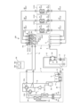
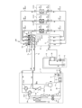
- 1 is a circuit diagram showing an example of a refrigeration cycle device 100 according to a first embodiment.
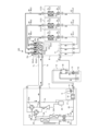
- 3 is an explanatory diagram of a flow of a refrigerant when the refrigeration cycle apparatus 100 according to the first embodiment is performing a cooling only operation.
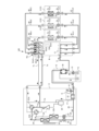
- FIG. 3 is an explanatory diagram of a flow of a refrigerant when the refrigeration cycle apparatus 100 according to the first embodiment is performing a full heating operation.
- FIG. 3 is an explanatory diagram of a flow of a refrigerant when the refrigeration cycle apparatus 100 according to the first embodiment is performing a cooling-dominant operation.
- FIG. 3 is an explanatory diagram of a flow of a refrigerant when the refrigeration cycle apparatus 100 according to the first embodiment is performing a heating-dominant operation.
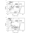
- FIG. FIG. 2 is a Mollier diagram of the refrigeration cycle apparatus 100 according to the first embodiment during cooling operation.
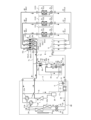
- FIG. 11 is a circuit diagram showing an example of a refrigeration cycle device 100 according to a second embodiment.
- 10 is an explanatory diagram of a flow of a refrigerant when the refrigeration cycle apparatus 100 according to the second embodiment is performing a full cooling operation.
- FIG. 10 is an explanatory diagram of a flow of a refrigerant when the refrigeration cycle apparatus 100 according to the second embodiment is performing a full heating operation.
- FIG. 10 is an explanatory diagram of a flow of a refrigerant when the refrigeration cycle apparatus 100 according to the second embodiment is performing a full heating operation.
- FIG. 11 is an explanatory diagram of a flow of a refrigerant when the refrigeration cycle apparatus 100 according to the third embodiment is performing a cooling-dominant operation.
- FIG. 11 is an explanatory diagram of a flow of a refrigerant when the refrigeration cycle apparatus 100 according to the third embodiment is performing a heating-dominant operation.
- FIG. 11 is an explanatory diagram of a flow of a refrigerant when the refrigeration cycle apparatus 100 according to the third embodiment is performing a heating-dominant operation.
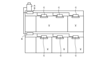
- FIG. 1 is a schematic diagram showing an example of the configuration of a refrigeration cycle device 100 according to embodiment 1.
- the refrigeration cycle device 100 includes a heat source device A, a relay device B connected to the heat source device A by piping, and a user side unit C installed in an air-conditioned space V.
- the refrigeration cycle device 100 is capable of simultaneous cooling and heating operation, in which each of the multiple user side units C can select and operate in cooling operation or heating operation.
- FIG. 1 is a schematic diagram showing an example of the configuration of a refrigeration cycle device 100 according to embodiment 1.
- the refrigeration cycle device 100 includes a heat source device A, a relay device B connected to the heat source device A by piping, and a user side unit C installed in an air-conditioned space V.
- the refrigeration cycle device 100 is capable of simultaneous cooling and heating operation, in which each of the multiple user side units C can select and operate in cooling operation or heating operation.
- the user unit C performs heat exchange with the air in each air-conditioned space V to perform cooling or heating, but it may also be used for purposes other than air conditioning, such as a water heater or a refrigerator.
- the refrigeration cycle device 100 may not only perform simultaneous cooling and heating operations, but may also perform mixed operations in which the user unit C performs water heating and refrigeration using a water heater or a refrigerator.
- the refrigeration cycle apparatus 100 includes a heat source unit A, a relay unit B, a user side unit C, and a heat medium converter D.
- the heat medium converter D is configured to use an external heat source E and to perform heat exchange between a heat medium carrying heat from the external heat source E and a refrigerant flowing through a refrigerant circuit of the refrigeration cycle apparatus 100.
- the external heat source E and the heat medium converter D are connected by a circuit in which a heat medium different from the refrigerant flowing between the heat source unit A, the relay unit B, and the user side unit C circulates.
- the heat medium converter D is configured to perform heat exchange between the heat medium having heat from the external heat source E and the refrigerant flowing into the heat medium converter D, and to function as a condenser or an evaporator by transferring heat or cold from the external heat source E to the refrigerant.
- the heat source unit A is usually placed in a space outside a building, such as a rooftop, and supplies cold or hot heat to the user units C1 and C2 via the relay unit B.
- the heat source unit A is not limited to being placed outdoors, and may be placed in an enclosed space, such as a machine room with a ventilation opening.
- the heat source unit A may also be placed inside a building if the waste heat can be exhausted outside the building through an exhaust duct.
- the heat source unit A may be placed inside a building as a water-cooled outdoor unit.
- unused heat such as heat contained in river water, exhaust gas from equipment, wastewater, and waste heat generated by equipment can also be used as the external heat source E.
- the heat medium such as water circulating through the heat medium circulation circuit 34 is heat exchanged with the refrigerant circulating through the heat source unit A, etc. in the heat medium heat exchanger 30.
- the heat transfer medium converter D may be configured to circulate the liquid, such as well water, of the external heat source E directly through the heat transfer medium circuit 34, or may be configured to circulate an independent heat medium, different from the liquid of the external heat source E, through the heat transfer medium circuit 34.
- an external heat source heat exchanger may be installed on the external heat source E side.
- one heat transfer medium converter D and one external heat source E are installed, but multiple units may be installed. In addition, multiple types of heat sources may be used as the external heat source E.
- the heat medium converter D can be used as an evaporator or a condenser is determined based on whether the temperature of the external heat source E is high or low, based on the evaporation temperature and condensation temperature of the refrigerant in the refrigeration cycle that circulates through the heat source unit A, relay unit B, user unit C, and heat medium converter D.
- the heat medium converter D is used as an evaporator
- the heat medium converter D is used as a condenser.
- the heat medium converter D when a relatively high-temperature external heat source E such as geothermal energy or sunlight is used, the heat medium converter D should be used as an evaporator, and when a relatively low-temperature external heat source E such as well water, snow and ice, or melted snow is used, the heat medium converter D should be used as a condenser.
- a relatively high-temperature external heat source E such as geothermal energy or sunlight
- a relatively low-temperature external heat source E such as well water, snow and ice, or melted snow
- the repeater B receives the refrigerant from the heat source unit A or the refrigerant that has passed through the heat medium converter D from the heat source unit A and distributes it to the multiple user units C.
- Each of the multiple user units C is connected in parallel to the repeater B, and the repeater B can also merge the refrigerant that has flowed into some of the user units C and allow it to flow into the other user units C.
- the repeater B has branching sections 10a, 10b, and 11 that branch and connect the liquid pipe 6, low pressure gas pipe 7a, and high pressure gas pipe 7b connected to the heat source unit A to the user units C.
- the heat source unit A includes a compressor 1, a heat source side heat exchanger 3, first flow switching devices 2a and 2b that switch the connection between the suction side or discharge side of the compressor 1 and the heat source side heat exchanger 3, a heat source side flow rate control device 22 that controls the flow rate of refrigerant flowing to the heat source side heat exchanger 3, and an accumulator 29.
- the heat source unit A further includes an auxiliary heat exchange unit G, which will be described later. Note that the auxiliary heat exchange unit G may not be installed in the heat source unit A.
- the heat source unit A and the relay unit B are connected by a liquid pipe 6, a low-pressure gas pipe 7a, and a high-pressure gas pipe 7b.
- the liquid pipe 6, the low-pressure gas pipe 7a, and the high-pressure gas pipe 7b are also called main pipes.
- the high-pressure gas pipe 7b is a pipe that allows the high-pressure refrigerant compressed by the compressor 1 to flow directly from the heat source unit A.
- the low-pressure gas pipe 7a is a pipe that allows the low-pressure gas refrigerant that has passed through the user unit C to flow into the heat source unit A, and is a pipe that returns the refrigerant from the relay unit B to the heat source unit A.
- the liquid pipe 6 is a pipe that allows the refrigerant that has been heat exchanged in the user unit C or the heat source unit A and has become liquid or in a two-phase gas-liquid state to flow.
- the compressor 1 draws in the refrigerant and compresses it to a high-temperature, high-pressure state, and is composed of, for example, an inverter compressor whose capacity can be controlled.
- the discharge side of the compressor 1 is connected to the high-pressure gas pipe 7b and the first flow path switching devices 2a and 2b.
- the high-pressure gas pipe 7b is one of the main pipes connecting the heat source unit A and the relay unit B, and is a pipe that supplies high-temperature, high-pressure gas refrigerant to the user unit C via the relay unit B.
- the heat source unit A is equipped with two first flow path switching devices 2a and 2b, with the first flow path switching device 2a connected to the heat source side heat exchanger 3a and the first flow path switching device 2b connected to the heat source side heat exchanger 3b.
- the first flow path switching devices 2a and 2b may be collectively referred to as the first flow path switching device 2.
- the first flow path switching device 2 is exemplified as a four-way switching valve.
- the heat source side heat exchanger 3 functions as an evaporator during heating operation and heating-dominated operation, and functions as a condenser or radiator during cooling operation and cooling-dominated operation.
- the heat source side heat exchangers 3a and 3b may be collectively referred to as the heat source side heat exchanger 3.
- the number of heat source side heat exchangers 3 is not limited to two, and may be one or three or more.
- the heat source side heat exchanger 3 is connected in series with the heat source side flow control device 22.
- An outdoor flow control device 3m is installed near the heat source side heat exchanger 3 to control the flow rate of a fluid such as outdoor air.
- outdoor air is sent to the heat source side heat exchanger 3 by the outdoor flow control device 3m, where heat exchange with the refrigerant takes place.
- the outdoor flow control device 3m is, for example, a fan that sends outdoor air to the heat source side heat exchanger 3.
- an air-cooled outdoor heat exchanger is used as an example of the heat source side heat exchanger 3
- an outdoor fan is used as an example of the outdoor flow control device 3m.
- the heat source side heat exchanger 3 may be a water-cooled outdoor heat exchanger or the like as long as the refrigerant exchanges heat with another fluid.
- the heat source side heat exchanger 3 exchanges heat between the refrigerant and the outdoor air, evaporating the refrigerant to gasify it or condensing it to liquefy it.
- the outdoor flow control device 3m forms an air path for the air flowing through the heat source side heat exchanger 3.
- the heat source side flow control device 22 is connected in series to the heat source side heat exchanger 3, and is provided between the liquid pipe 6 and the heat source side heat exchanger 3, and is configured to be freely opened and closed.
- the heat source side flow control device 22 adjusts the flow rate of refrigerant flowing from the heat source side heat exchanger 3 to the liquid pipe 6 during cooling operation, and adjusts the flow rate of refrigerant flowing from the liquid pipe 6 to the heat source side heat exchanger 3 during heating operation.
- the heat source side flow control device 22 is configured so that the flow resistance changes continuously.
- the heat source side flow control device 22 also functions as an expansion valve, reducing the pressure of the flowing refrigerant.
- the accumulator 29 is provided on the suction side of the compressor 1 and stores excess refrigerant due to differences between heating and cooling operation or excess refrigerant due to transient changes in operation.
- the accumulator 29 is connected to the low-pressure gas pipe 7a and the first flow path switching device 2.
- an auxiliary heat exchange unit G is installed in the heat source unit A.
- the auxiliary heat exchange unit G includes a bypass pipe 17 that connects the liquid pipe 6 and the pipe 1b connected to the suction side of the compressor 1.
- a bypass flow rate control device 15 is provided on the bypass pipe 17, and a refrigerant pipe heat exchanger 16 is provided to exchange heat between the refrigerants flowing through the bypass pipe 17 and the pipe 26 that connects the liquid pipe 6 and the heat source side flow rate control device 22.
- the auxiliary heat exchange unit G may be installed outside the heat source unit A.
- the relay B includes a low-pressure side branch 10a connected to the low-pressure gas pipe 7a, a high-pressure side branch 10b connected to the high-pressure gas pipe 7b, and a second branch 11 connected to the liquid pipe 6.
- the low-pressure side branch 10a is connected to a first pipe 40 extending from the utilization side heat exchanger 5c of the utilization side unit C via a low-pressure side solenoid valve 9.
- the high-pressure side branch 10b is connected to the first pipe 40 via a high-pressure side solenoid valve 8.
- the low-pressure side solenoid valve 9 and the high-pressure side solenoid valve 8 are configured to select the connection between the utilization side unit C and the low-pressure gas pipe 7a or the high-pressure gas pipe 7b, respectively, and switch the connection depending on whether the utilization side heat exchanger 5c of the utilization side unit C functions as a condenser or an evaporator.
- the low-pressure side solenoid valve 9 and the high-pressure side solenoid valve 8 may be collectively referred to as a second flow path switching device 10c.
- the low-pressure side branch portion 10 a, the high-pressure side branch portion 10 b, and the second flow path switching device 10 c are collectively referred to as a first branch portion 10.
- the low-pressure side solenoid valve 9 and the high-pressure side solenoid valve 8 are installed on each of the two pipes that branch off from the first pipe 40, but they may also be configured using, for example, a three-way valve. In other words, other structures may be used as long as the first pipe 40 of the user side unit C and the heat medium converter D is configured to connect to either the low-pressure gas pipe 7a or the high-pressure gas pipe 7b. In addition, it is preferable that the low-pressure side solenoid valve 9 and the high-pressure side solenoid valve 8 are configured so that they can be closed to prevent the refrigerant from flowing to any of the user side units C.
- the second branching section 11 is connected to the second pipe 41 extending from the usage-side flow control device 4c of the usage-side unit C.
- the second branching section 11 is also connected to the liquid pipe 6, and distributes the refrigerant from the liquid pipe 6 to multiple usage-side units C, merges the refrigerant from multiple usage-side units C and sends it to the liquid pipe 6, or merges the refrigerant from some of the usage-side units C and distributes it to other usage-side units C and the liquid pipe 6.
- the user side units C are installed at positions where they can supply conditioned air to a space to be air-conditioned, such as a room, and supply cooled air or heated air to the space to be air-conditioned by using cold or hot heat from the heat source unit A supplied via the relay unit B.
- the user side units C1 and C2 each have a built-in user side heat exchanger 5c1, 5c2, 5c3 and a user side flow control device 4c1, 4c2, 4c3.
- the user side heat exchangers 5c1, 5c2, and 5c3 may be collectively referred to as the user side heat exchanger 5c
- the user side flow control devices 4c1, 4c2, and 4c3 may be collectively referred to as the user side flow control device 4c.
- Each of the utilization side heat exchangers 5c exchanges heat between the air supplied from the flow control device 5m and the refrigerant to generate heated air or cooled air to be supplied to the space to be air-conditioned.
- the flow control device 5m forms an air path for the air flowing to the utilization side heat exchanger 5c.
- the utilization side flow control device 4c is provided between the second branch section 11 of the relay unit B and the utilization side heat exchanger 5c, and is configured to be freely opened and closed. The utilization side flow control device 4c adjusts the flow rate of the refrigerant flowing into the utilization side heat exchanger 5c.
- the heat medium relay unit D is for supplying heat or cold from an external heat source E to a refrigerant circulating in the refrigeration cycle apparatus 100.
- the heat medium relay unit D has an intermediate heat exchanger 30 that exchanges heat between the refrigerant circulating in the heat source unit A, the relay unit B, and the user side unit C and a heat medium that carries heat from the external heat source E.
- the heat medium converter D is installed in the liquid pipe 6.
- the refrigerant flowing through the liquid pipe 6 passes through the heat medium heat exchanger 30 that the heat medium converter D has.
- the heat medium that carries the heat or cold of the external heat source E is circulated through the heat medium circulation circuit 34 by the pump 31, and is sent from the external heat source E to the heat medium-intermediate heat exchanger 30.
- the heat medium-intermediate heat exchanger 30 is, for example, a plate-type heat exchanger, inside which the refrigerant and heat medium circulate, and the heat or cold of the heat medium is transferred to the refrigerant.
- the heat medium converter D is equipped with external heat source temperature sensors 32 and 33.
- the external heat source temperature sensor 32 detects the temperature of the heat medium flowing into the heat medium-to-heat medium heat exchanger 30.
- the external heat source temperature sensor 33 detects the temperature of the heat medium flowing out of the heat medium-to-heat medium heat exchanger 30.
- the external heat source E is, for example, well water, melted snow, ice and snow, geothermal heat, solar light, etc., and the heat medium can be changed appropriately depending on the target heat source.
- the external heat source E is well water stored in a large amount in a well underground
- the well water is pumped up by a pump 31 to become a heat medium, and is caused to flow into the heat medium heat exchanger 30 by a heat medium circulation circuit 34.
- the well water exchanges heat with the refrigerant, flows out of the heat medium heat exchanger 30, and its temperature increases.
- the well water with the increased temperature is returned to the well.
- the well water that serves as the external heat source E is stored in a large amount underground, and even if the temperature increases through the heat medium converter D and the water resistance is returned, the temperature of the external heat source E hardly changes.
- the heat medium circulation circuit 34 may be configured to circulate an independent heat medium in the heat medium circulation circuit 34.
- the heat medium circulation circuit 34 may be connected to an external heat exchanger F that exchanges heat between the external heat source E and the heat medium flowing through the heat medium circulation circuit 34.
- the external heat exchanger F exchanges heat between the heat medium and the external heat source E.
- the heat medium that has been heat exchanged in the external heat exchanger F is sent to the heat medium-to-heat medium heat exchanger 30 and is heat exchanged with the refrigerant circulating through the refrigerant circuit of the refrigeration cycle device 100.
- the quality of the heat medium flowing through the heat medium circulation circuit 34 can be maintained, and the durability of the heat medium circulation circuit 34 and the heat medium converter D can be ensured, as opposed to pumping up well water as the heat medium, for example.
- the configuration of the heat medium circulation circuit 34 may be changed as appropriate depending on what is used as the external heat source E.
- the refrigeration cycle device 100 makes effective use of such an external heat source E to achieve energy savings.
- the refrigeration cycle apparatus 100 is provided with a control device 50.
- the control device 50 controls actuators and the like based on refrigerant pressure information, refrigerant and heat medium temperature information, outdoor temperature information, indoor temperature information, and the like detected by each sensor provided in the refrigeration cycle apparatus 100.
- the control device 50 controls driving of the compressor 1, switching between the first flow path switching device 2 and the second flow path switching device 10c, driving of the fan motor of the outdoor flow control device 3m, driving of the fan motor of the flow control device 5m, and the pump 31 that sends the heat medium to the heat source side heat exchanger 3.
- the control device 50 also controls the opening of the heat source side flow control device 22, the utilization side flow control device 4c, and the bypass flow control device 15.
- the control device 50 includes a memory 50a in which information for determining each control value is stored.
- the control device 50 may be configured as hardware such as a control circuit that realizes its functions.
- the control device 50 may also be configured as a software program stored in a storage unit such as a semiconductor memory, and a calculation device 50b such as a microcomputer or CPU (Central Processing Unit) that executes the software program.
- the control device 50 is shown independently, but it may be provided in the heat source unit A, the relay unit B, the utilization side unit C, etc.
- the number of control devices 50 may be one or more than three.
- the control device 50 is connected to each device to be controlled by wire or wirelessly.
- the control device 50 is not shown in FIG. 3 and subsequent figures.
- the operation of the refrigeration cycle apparatus 100 includes a cooling operation and a heating operation.
- the cooling operation includes a cooling-dominated operation in which a heating operation is performed in some of the user-side units C.
- the heating operation includes a heating-dominated operation in which a cooling operation is performed in some of the user-side units C.
- Cooling operation is an operation mode in which all user side units C are either in cooling operation or stopped.
- Heating operation is an operation mode in which all user side units C are either in heating operation or stopped.
- Cooling-dominated operation is an operation mode in which heating or cooling can be selected for each indoor unit, and the cooling load is greater than the heating load.
- Cooling-dominated operation is an operation mode in which the heat source side heat exchanger 3 is connected to the discharge side of the compressor 1 and acts as a condenser.
- Heating-dominated operation is an operation mode in which heating or cooling can be selected for each indoor unit, and the heating load is greater than the cooling load.
- Heating-dominated operation is an operation mode in which the heat source side heat exchanger 3 is connected to the suction side of the compressor 1 and acts as an evaporator.
- FIG. 3 is an explanatory diagram of the flow of the refrigerant when the refrigeration cycle apparatus 100 according to the embodiment 1 is in a full cooling operation.
- Fig. 3 shows a state when all the user side units C are in a cooling operation, and all the user side heat exchangers 5c function as evaporators.
- the control device 50 switches the first flow path switching device 2a so that the refrigerant discharged from the compressor 1 flows to the heat source side heat exchanger 3.
- the low pressure side solenoid valves 9c1, 9c2, and 9c3 connected to the user side unit C1 are opened, and the high pressure side solenoid valves 8c1, 8c2, and 8c3 are closed.
- the closed valves of the second flow path switching device 10c are shown in black.
- the thick solid lines indicate that high pressure refrigerant is circulating
- the thin solid lines indicate that low pressure refrigerant is circulating
- the thick dashed lines indicate that medium pressure refrigerant is circulating.
- the parts of the refrigeration cycle circuit indicated by thin dashed lines are not circulated by refrigerant.
- the low-temperature, low-pressure gaseous refrigerant is compressed by the compressor 1 and discharged as a high-temperature, high-pressure gaseous refrigerant.
- the high-temperature, high-pressure gaseous refrigerant discharged from the compressor 1 flows into the heat source side heat exchanger 3 via the first flow switching device 2.
- the refrigerant discharged from the compressor 1 and flowing into the heat source side heat exchanger 3 is cooled while heating the outdoor air, and becomes a medium-temperature, high-pressure liquid refrigerant or a gas-liquid two-phase refrigerant.
- the medium-temperature, high-pressure refrigerant that flows out of the heat source side heat exchanger 3 flows out of the heat source unit A and flows into the liquid pipe 6.
- the refrigerant that flows into the liquid pipe 6 is further cooled by the heat medium heat exchanger 30 installed on the liquid pipe 6. This condenses the refrigerant to a temperature equivalent to the lower temperature of the external heat source E, ensures the enthalpy difference between the refrigerant before and after condensation, and makes it possible to further improve the cooling capacity.
- the refrigerant then heats up while cooling the indoor air, becoming a low-temperature, low-pressure gaseous refrigerant.
- the low-temperature, low-pressure gaseous refrigerant flowing out of the user-side heat exchangers 5c1, 5c2, and 5c3 passes through the low-pressure solenoid valves 9c1, 9c2, and 9c3, respectively, and flows into the low-pressure branch 10a of the first branch 10.
- the low-temperature, low-pressure gaseous refrigerant that joins at the low-pressure branch 10a flows into the heat source unit A from the low-pressure gas pipe 7a, passes through the accumulator 29, is sucked into the compressor 1, and is compressed.
- FIG. 4 is an explanatory diagram of the flow of the refrigerant when the refrigeration cycle apparatus 100 according to the embodiment 1 is in full heating operation.
- Fig. 3 shows a state when all the user side units C are in heating operation, and all the user side heat exchangers 5c function as condensers.
- the control device 50 switches the first flow path switching device 2a so that the refrigerant discharged from the compressor 1 flows out of the heat source unit A into the high-pressure gas pipe 7b.
- the high-pressure side solenoid valves 8c1, 8c2, and 8c3 connected to the user side unit C1 are opened, and the low-pressure side solenoid valves 9c1, 9c2, and 9c3 are closed.
- the first flow path switching device 2a is switched to connect the heat source side heat exchanger 3 and the suction side of the compressor 1.
- the low-temperature, low-pressure gaseous refrigerant is compressed by the compressor 1 and discharged as high-temperature, high-pressure gaseous refrigerant.
- the high-temperature, high-pressure gaseous refrigerant discharged from the compressor 1 leaves the heat source unit A and flows into the high-pressure gas pipe 7b, and flows from the first branch 10 through the first piping 40c1, 40c2, and 40c3 into the user side unit C.
- the refrigerant that flows into the user side unit C is cooled in the user side heat exchanger 5c while heating the indoor air, and becomes a medium-temperature, high-pressure liquid refrigerant or a two-phase gas-liquid refrigerant.
- the medium-temperature, high-pressure refrigerant that flows out of the user side heat exchanger 5c is depressurized by the user side flow control device 4c and becomes a low-temperature, low-pressure two-phase gas-liquid state.
- the refrigerant that flows into the liquid pipe 6 is heated by the heat medium heat exchanger 30 provided on the liquid pipe 6. As a result, the refrigerant flowing through the liquid pipe 6 can be evaporated using the external heat source E.
- the refrigerant in the liquid pipe 6 flows into the heat source unit A, passes through the heat source side flow control device 22, and flows into the heat source side heat exchanger 3.
- the refrigerant is also heated in the heat source side heat exchanger 3, becoming a low-temperature, low-pressure gas refrigerant. Because the refrigerant has already been heated in the heat medium heat exchanger 30, the heat exchange capacity of the heat source side heat exchanger 3 can also be reduced.
- the heat medium heat exchanger 30 and the heat source side heat exchanger 3 are connected in series on the refrigeration cycle circuit, and the heat medium heat exchanger 30 functions to supplement the capacity of the heat source side heat exchanger 3.
- the low-temperature, low-pressure gaseous refrigerant that flows out of the heat source side heat exchanger 3 passes through the first flow switching device 2 and flows into the pipe 1b, passes through the accumulator 29, and is sucked into the compressor 1 and compressed.
- FIG. 5 is an explanatory diagram of the flow of refrigerant when the refrigeration cycle apparatus 100 according to embodiment 1 is operating mainly in cooling mode.
- Fig. 5 illustrates a state in which the user side units C1 and C2 among the user side units C are operating in cooling mode and the user side unit C3 is operating in heating mode, with the user side heat exchangers 5c1 and 5c2 functioning as evaporators and the user side heat exchanger 5c3 functioning as a condenser.
- the low-temperature, low-pressure gaseous refrigerant is compressed by the compressor 1 and discharged as a high-temperature, high-pressure gaseous refrigerant.
- a portion of the high-temperature, high-pressure gaseous refrigerant discharged from the compressor 1 flows out of the heat source unit A and into the high-pressure gas pipe 7b, and the other portion flows into the heat source side heat exchanger 3 via the first flow switching device 2.
- the refrigerant discharged from the compressor 1 and flowing into the high-pressure gas pipe 7b flows from the high-pressure side branching section 10b into the user side unit C3 operating in heating mode, and is cooled while heating the outdoor air in the user side heat exchanger 5c3, becoming a medium-temperature, high-pressure liquid refrigerant or a gas-liquid two-phase refrigerant.
- the refrigerant that leaves the user side heat exchanger 5c3 is decompressed by the user side flow control device 4c3 and becomes a low-temperature, low-pressure gas-liquid two-phase state. Note that the user side flow control device 4c3 does not need to decompress depending on the state of the refrigerant.
- the refrigerant that flows into the heat source side heat exchanger 3 is cooled while heating the outdoor air, becoming a medium temperature and high pressure liquid refrigerant or a gas-liquid two-phase refrigerant.
- the medium temperature and high pressure refrigerant that flows out of the heat source side heat exchanger 3 flows out of the heat source unit A and into the liquid pipe 6.
- the refrigerant that flows into the liquid pipe 6 is further cooled by the inter-heat medium heat exchanger 30 provided on the liquid pipe 6.
- the inter-heat medium heat exchanger 30 and the heat source side heat exchanger 3 are connected in series on the refrigeration cycle circuit, and the inter-heat medium heat exchanger 30 functions to supplement the capacity of the heat source side heat exchanger 3.
- the flow path through which the refrigerant flows in this order from the heat source unit A to the heat medium converter D is sometimes called the auxiliary refrigerant flow path.
- the refrigerant is shown to flow only through the heat source-side heat exchanger 3b, and the refrigeration cycle device 100 can perform cooling-dominated operation using only the heat source-side heat exchanger 3b by using the heat medium converter D.
- the refrigerant condensed in the heat exchanger 30 installed on the liquid pipe 6 flows into the second branch 11 of the relay B.
- the refrigerant flowing in from the user unit C3 and the refrigerant flowing in from the liquid pipe 6 join together and flow into the second pipes 41c1, 41c2 that are branched and connected to the user units C1 and C2 that are operating in cooling mode.
- the refrigerant that flows through the second pipes 41c1, 41c2 flows into the user side flow control devices 4c1, 4c2 of the user side units C1, C2, where it is throttled, expanded and reduced in pressure, becoming a low-temperature, low-pressure two-phase gas-liquid state.
- the low-temperature, low-pressure gaseous refrigerant flowing out of the user-side heat exchangers 5c1 and 5c2 passes through the low-pressure solenoid valves 9c1 and 9c2, respectively, and flows into the low-pressure branch 10a of the first branch 10.
- the low-temperature, low-pressure gaseous refrigerant that joins at the low-pressure branch 10a flows into the heat source unit A from the low-pressure gas pipe 7a, passes through the accumulator 29, is sucked into the compressor 1, and is compressed.
- FIG. 6 is an explanatory diagram of the flow of the refrigerant when the refrigeration cycle apparatus 100 according to the embodiment 1 is in heating-dominated operation.
- Fig. 6 illustrates a state in which the user-side units C1 and C2 among the user-side units C are in heating operation and the user-side unit C3 is in cooling operation, in which the user-side heat exchangers 5c1 and 5c2 function as condensers and the user-side heat exchanger 5c3 functions as an evaporator.
- the control device 50 switches the first flow path switching device 2a so that the refrigerant discharged from the compressor 1 flows from the heat source unit A to the high-pressure gas pipe 7b.
- the high-pressure side solenoid valves 8c1, 8c2 connected to the user side units C1 and C2 performing heating operation are opened, and the low-pressure side solenoid valves 9c1, 9c2 are closed.
- the high-pressure side solenoid valve 8c3 connected to the user side unit C3 performing cooling operation is closed, and the low-pressure side solenoid valve 9c3 is closed.
- the first flow path switching device 2a is switched to connect the heat source side heat exchanger 3 to the suction side of the compressor 1.
- the low-temperature, low-pressure gaseous refrigerant is compressed by the compressor 1 and discharged as a high-temperature, high-pressure gaseous refrigerant.
- the high-temperature, high-pressure gaseous refrigerant discharged from the compressor 1 leaves the heat source unit A and flows into the high-pressure gas pipe 7b, and flows from the first branch 10 through the first piping 40c1, 40c2 into the user-side units C1 and C2.
- the refrigerant that flows into the user-side units C1 and C2 is cooled while heating the indoor air in the user-side heat exchanger 5c, and becomes a medium-temperature, high-pressure liquid refrigerant or a gas-liquid two-phase refrigerant.
- the medium-temperature, high-pressure refrigerant that flows out of each of the user-side heat exchangers 5c1, 5c2 is depressurized by each of the user-side flow control devices 4c1, 4c2, and becomes a low-temperature, low-pressure gas-liquid two-phase state. Note that the user-side flow control devices 4c1, 4c2 do not need to depressurize depending on the state of the refrigerant.
- the low-temperature, low-pressure two-phase gas-liquid refrigerant flowing out of the user-side flow control devices 4c1 and 4c2 passes through the second branch 11, with some flowing from the relay unit B into the liquid pipe 6 and the other flowing into the second pipe 41c3 connected to the user-side unit C2 performing cooling operation.
- the refrigerant flowing into the second pipe 41c3 is depressurized by the user-side flow control device 4c3, and evaporates in the user-side heat exchanger 5c3 while cooling the indoor air, becoming a low-temperature, low-pressure gas refrigerant.
- the refrigerant leaving the user-side unit C3 passes through the first branch 10 and flows into the heat source unit A from the low-pressure gas pipe 7a.
- the refrigerant that flows into the liquid pipe 6 is heated by the heat exchanger 30 installed on the liquid pipe 6. As a result, the refrigerant flowing through the liquid pipe 6 can be evaporated using the external heat source E.
- the refrigerant in the liquid pipe 6 flows into the heat source unit A and into the heat source side heat exchanger 3 via the heat source side flow control device 22.
- the refrigerant is also heated in the heat source side heat exchanger 3, becoming a low-temperature, low-pressure gas refrigerant. Since the refrigerant has already been heated in the heat medium heat exchanger 30, the heat exchange capacity of the heat source side heat exchanger 3 can be reduced.
- the refrigerant is shown to flow only through the heat source side heat exchanger 3b, and the refrigeration cycle device 100 can perform heating-dominated operation using only the heat source side heat exchanger 3b by using the heat medium converter D.
- the heat medium heat exchanger 30 and the heat source side heat exchanger 3 are connected in series on the refrigeration cycle circuit, and the heat medium heat exchanger 30 functions to supplement the capacity of the heat source side heat exchanger 3.
- the low-temperature, low-pressure gaseous refrigerant that flows out of the heat source side heat exchanger 3 flows into the pipe 1b via the first flow switching device 2.
- the refrigerant that flows out of the relay unit B and into the heat source unit A via the low-pressure gas pipe 7a also flows into the pipe 1b, passes through the accumulator 29, and is sucked into the compressor 1 and compressed.
- the refrigeration cycle apparatus 100 includes a heat source unit A having a compressor 1 that compresses a refrigerant, a heat source side heat exchanger 3, and a first flow path switching device 2 that switches a connection between the heat source side heat exchanger 3 and the suction side or the discharge side of the compressor 1, a high-pressure gas pipe 7b that is connected to the discharge side of the compressor 1 and through which the refrigerant flows out of the heat source unit A, a low-pressure gas pipe 7a that is connected to the suction side of the compressor 1 and through which the refrigerant flows into the heat source unit A, a user side unit C having a user side heat exchanger 5c and a user side flow control device 4c that controls the flow rate of the refrigerant flowing through the user side heat exchanger 5c, a heat medium converter D having an inter-heat medium heat exchanger 30 that exchanges heat between the refrigerant and a heat medium that carries heat from an
- the utilization side heat exchanger 5c is configured to be selectively connectable to the high pressure gas pipe 7b or the low pressure gas pipe 7a, and the utilization side flow rate control device 4c is connected to the liquid pipe 6.
- the heat medium heat exchanger 30 is connected to at least the liquid pipe 6, and replaces or assists the function of the heat source side heat exchanger 3.
- the refrigeration cycle device 100 has three main pipes, namely, a low-pressure gas pipe 7a, a high-pressure gas pipe 7b, and a liquid pipe 6, extending from the heat source unit A, and can use an external heat source E to supplement the heat source side heat exchanger 3.
- the heat medium heat exchanger 30 is connected in series with the heat source side heat exchanger 3 by piping, and performs the same function as the heat source side heat exchanger 3 functioning as an evaporator or condenser.
- the heat medium heat exchanger 30 can be used as a substitute for the heat source side heat exchanger 3 without using the heat source side heat exchanger 3.
- FIG. 7 is a Mollier diagram of the refrigeration cycle apparatus 100 according to the first embodiment during operation.
- FIG. 7(a) shows the Mollier diagram during cooling operation
- FIG. 7(b) shows the Mollier diagram during heating operation.
- the Mollier diagram of the refrigeration cycle apparatus 100 according to the first embodiment is shown by a thick solid line.
- the heat source side heat exchanger 3 functions as a condenser during cooling operation
- the heat medium heat exchanger 30 also functions as a condenser, thereby making it possible to increase the enthalpy difference of the refrigerant before and after passing through the condenser.
- the heat source unit A of the refrigeration cycle device 100 includes a first flow path to which the heat source side heat exchanger 3 and the heat source side flow control device 22 that controls the flow rate of the refrigerant flowing through the heat source side heat exchanger 3 are connected.
- the first flow path switching device 2 is configured to be able to switch the connection between the first flow path and the discharge side or the suction side of the compressor 1.
- the heat medium heat exchanger 30 is connected in series on the liquid pipe 6.
- the refrigeration cycle apparatus 100 can heat or cool the refrigerant flowing in the liquid pipe 6 by the heat medium converter D using the heat or cold of the external heat source E, and the external heat source E can be used to assist the heat source side heat exchanger 3.
- the heat exchange capacity of the refrigeration cycle apparatus 100 is improved, and it becomes possible to operate with the heat exchange capacity of the heat source side heat exchanger 3 reduced, enabling further energy-saving operation.
- Embodiment 2 The refrigeration cycle apparatus 100 according to the second embodiment is obtained by modifying the circuit structure of the refrigeration cycle apparatus 100 according to the first embodiment. Specifically, in the first embodiment, the heat medium relay unit D is connected in series to the user side unit C and the heat source unit A, whereas in the second embodiment, the heat medium relay unit D is connected in parallel to the heat source unit A. The following description will focus on the differences between the second embodiment and the first embodiment.
- FIG. 8 is a circuit diagram showing an example of a refrigeration cycle apparatus 100 according to embodiment 2.
- the heat medium converter D is connected not only to the liquid pipe 6 but also to the low-pressure gas pipe 7a and the high-pressure gas pipe 7b.
- the heat medium converter D includes an intermediate heat exchanger 30, as in embodiment 1, and the intermediate heat exchanger 30 is connected to an external heat source E.
- the first pipe 40d and the second pipe 41d extend from the intermediate heat exchanger 30, and the refrigerant is configured to flow through the intermediate heat exchanger 30.
- the first pipe 40d1 branches and is connected to the high pressure gas pipe 7b or the low pressure gas pipe 7a so that the refrigerant can be selected.
- the second pipe 41d is connected to the liquid pipe 6.
- the second pipe 41d is equipped with a refrigerant flow control device 4d.
- the flow path in which the heat medium converter D is installed may be referred to as the second flow path 60.
- the second flow path 60 is a flow path that connects the main low pressure gas pipe 7a or the high pressure gas pipe 7b to the liquid pipe 6.
- the connection between the second flow path 60 and the low pressure gas pipe 7a or the high pressure gas pipe 7b is switched by opening and closing the low pressure side solenoid valve 9d and the high pressure side solenoid valve 8d.
- the flow rate of the refrigerant flowing through the second flow path 60 is controlled by the refrigerant flow control device 4d.
- the refrigerant flow control device 4d may be built into the heat medium converter D.
- FIG. 9 is an explanatory diagram of the flow of the refrigerant when the refrigeration cycle apparatus 100 according to the second embodiment is in a full cooling operation.
- Fig. 9 illustrates a state when all the user side units C are in a cooling operation, and all the user side heat exchangers 5c function as evaporators.
- the control device 50 switches the first flow path switching device 2a so that the refrigerant discharged from the compressor 1 flows to the heat source side heat exchanger 3.
- the low pressure side solenoid valves 9c1, 9c2, and 9c3 connected to the user side unit C1 are opened, and the high pressure side solenoid valves 8c1, 8c2, and 8c3 are closed.
- the high pressure side solenoid valve 8d of the second flow path 60 in which the heat medium converter D is installed is opened and the low pressure side solenoid valve 9d is closed, the refrigerant discharged from the compressor 1 flows into the second flow path 60 in which the heat medium converter D is installed via the high pressure gas pipe 70b.
- the high pressure side solenoid valve 8d and the low pressure side solenoid valve 9d of the second flow path 60 are displayed as closed valves in black.
- the low-temperature, low-pressure gaseous refrigerant is compressed by the compressor 1 and discharged as high-temperature, high-pressure gaseous refrigerant.
- the high-temperature, high-pressure gaseous refrigerant discharged from the compressor 1 flows into the first flow path 20 in which the heat source side heat exchanger 3 and the heat source side flow control device 22 are installed via the first flow path switching device 2.
- the refrigerant discharged from the compressor 1 and flowing into the heat source side heat exchanger 3 is cooled while heating the outdoor air, and becomes a medium-temperature, high-pressure liquid refrigerant or a gas-liquid two-phase refrigerant.
- the medium-temperature, high-pressure refrigerant flowing out of the heat source side heat exchanger 3 flows out of the heat source unit A and into the liquid pipe 6.
- the refrigerant discharged from the compressor 1 branches off from the pipe 1a, flows out of the heat source unit A, and flows into the second flow path 60 via the high-pressure gas pipe 7b.
- the refrigerant that flows into the second flow path 60 is condensed in the heat medium heat exchanger 30, and flows into the liquid pipe 6 via the refrigerant flow control device 4d.
- the refrigerant that has passed through the second flow path 60 and the refrigerant that has passed through the heat source side heat exchanger 3 join here and flow into the second branch section 11.
- the refrigerant that has flowed into the second branch section 11 returns to the heat source unit A via the user side unit C and the relay unit B, as in the full cooling operation in embodiment 1.
- the intermediate heat exchanger 30 is arranged in parallel with the heat source side heat exchanger 3.
- the refrigeration cycle apparatus 100 according to the second embodiment can flow refrigerant to the intermediate heat exchanger 30 through a path independent of the heat source side heat exchanger 3, thereby increasing the condenser capacity.
- the refrigerant may be sent only to the second flow path 60, and the heat source side flow control device 22 may be closed so that the refrigerant is not sent to the heat source side heat exchanger 3.
- FIG. 10 is an explanatory diagram of the flow of the refrigerant when the refrigeration cycle apparatus 100 according to the second embodiment is in full heating operation.
- Fig. 10 illustrates a state when all the user side units C are in heating operation, and all the user side heat exchangers 5c function as condensers.
- the control device 50 switches the first flow path switching device 2a so that the refrigerant discharged from the compressor 1 flows out of the heat source unit A into the high-pressure gas pipe 7b.
- the high-pressure side solenoid valves 8c1, 8c2, and 8c3 connected to the user side unit C1 are opened, and the low-pressure side solenoid valves 9c1, 9c2, and 9c3 are closed.
- the first flow path switching device 2a is switched to connect the heat source side heat exchanger 3 and the suction side of the compressor 1.
- compressor 1 When compressor 1 starts operating, low-temperature, low-pressure gaseous refrigerant is compressed by compressor 1 and discharged as high-temperature, high-pressure gaseous refrigerant. As in the full heating operation of embodiment 1, the high-temperature, high-pressure gaseous refrigerant discharged from compressor 1 leaves heat source unit A and flows into high-pressure gas pipe 7b, then flows from first branch 10 through first piping 40c1, 40c2, and 40c3 into user unit C. The refrigerant that flows into user unit C is condensed and decompressed, flows out of relay unit B through second branch 11, and flows into liquid pipe 6.
- the intermediate heat exchanger 30 is arranged in parallel with the heat source side heat exchanger 3.
- the refrigeration cycle apparatus 100 according to the second embodiment can flow refrigerant to the intermediate heat exchanger 30 through a path independent of the heat source side heat exchanger 3, thereby increasing the evaporator capacity.
- the heat medium converter D has a high capacity as an evaporator
- the refrigerant may be sent only to the second flow path 60, and the heat source side flow control device 22 may be closed so that the refrigerant is not sent to the heat source side heat exchanger 3. In this way, energy-saving operation can be achieved by partially using the cold energy of the external heat source E to evaporate the refrigerant.
- FIG. 11 is an explanatory diagram of the flow of refrigerant when the refrigeration cycle apparatus 100 according to embodiment 2 is operating mainly in cooling mode.
- Fig. 11 illustrates a state in which the user side units C1 and C2 among the user side units C are operating in cooling mode and the user side unit C3 is operating in heating mode, with the user side heat exchangers 5c1 and 5c2 functioning as evaporators and the user side heat exchanger 5c3 functioning as a condenser.
- the control device 50 switches the first flow path switching device 2a so that the refrigerant discharged from the compressor 1 flows to the heat source side heat exchanger 3.
- the low pressure side solenoid valves 9c1 and 9c2 connected to the utilization side units C1 and C2 are opened, and the low pressure side solenoid valve 9c3 connected to the utilization side unit C3 is closed.
- the high pressure side solenoid valves 8c1 and 8c2 are closed, and the high pressure side solenoid valve 8c3 is open.
- the high-pressure side solenoid valve 8d installed in the second flow path 60 is opened so that the refrigerant flowing in the high-pressure gas pipe 7b also branches off and flows in the second flow path 60 in which the heat medium converter D is installed.
- the low-temperature, low-pressure gaseous refrigerant is compressed by the compressor 1 and discharged as a high-temperature, high-pressure gaseous refrigerant.
- a portion flows out of the heat source unit A and enters the high-pressure gas pipe 7b, and the other portion flows into the heat source side heat exchanger 3 via the first flow path switching device 2.
- a portion of the refrigerant discharged from the compressor 1 and flowing into the high-pressure gas pipe 7b flows from the high-pressure side branch 10b into the user side unit C3, which is operating in heating mode, as in the cooling-dominated operation in embodiment 1.
- the remaining portion of the refrigerant that flowed into the high-pressure gas pipe 7b flows into the second flow path 60 and is condensed in the heat medium heat exchanger 30.
- a portion of the refrigerant flowing into the high-pressure gas pipe 7b is condensed in the heat medium converter D by utilizing the cold heat of the external heat source E.
- the refrigerant that flows through the second flow path 60 merges with the refrigerant that flows through the first flow path 20, where the heat source side heat exchanger 3 is installed, in the liquid pipe 6, and flows into the second branch section 11 of the relay unit B.
- the refrigerant that flows into the second branch 11 is a mixture of refrigerant condensed in the heat source heat exchanger 3, the heat medium heat exchanger 30, and the user side heat exchanger 5c3 in heating operation, and flows into the user side units C1 and C2 in cooling operation.
- the refrigerant that flows out of the user side units C1 and C2 passes through the low pressure side solenoid valves 9c1 and 9c2, respectively, and flows into the low pressure side branch 10a of the first branch 10.
- the low temperature, low pressure gaseous refrigerant that flows into the low pressure side branch 10a flows into the heat source unit A from the low pressure gas pipe 7a, passes through the accumulator 29, is sucked into the compressor 1, and is compressed.
- the heat medium heat exchanger 30 is arranged in parallel with the heat source side heat exchanger 3 even during cooling-dominated operation, just as during full cooling operation, and the capacity of the condenser can be increased.
- FIG. 12 is an explanatory diagram of the flow of the refrigerant when the refrigeration cycle apparatus 100 according to the embodiment 2 is in heating-dominated operation.
- Fig. 12 illustrates a state in which the user-side units C1 and C2 among the user-side units C are in heating operation and the user-side unit C3 is in cooling operation, in which the user-side heat exchangers 5c1 and 5c2 function as condensers and the user-side heat exchanger 5c3 functions as an evaporator.
- the control device 50 switches the first flow path switching device 2a so that the refrigerant discharged from the compressor 1 flows from the heat source unit A to the high-pressure gas pipe 7b.
- the high-pressure side solenoid valves 8c1, 8c2 connected to the user side units C1 and C2 performing heating operation are opened, and the low-pressure side solenoid valves 9c1, 9c2 are closed.
- the high-pressure side solenoid valve 8c3 connected to the user side unit C3 performing cooling operation is closed, and the low-pressure side solenoid valve 9c3 is closed.
- the first flow path switching device 2a is switched to connect the heat source side heat exchanger 3 to the suction side of the compressor 1.
- the low-temperature, low-pressure gaseous refrigerant is compressed by the compressor 1 and discharged as a high-temperature, high-pressure gaseous refrigerant.
- the high-temperature, high-pressure gaseous refrigerant discharged from the compressor 1 leaves the heat source unit A and flows into the high-pressure gas pipe 7b, and flows from the first branch 10 through the first piping 40c1, 40c2 into the user-side units C1 and C2.
- the refrigerant that flows into the user-side units C1 and C2 is cooled while heating the indoor air in the user-side heat exchanger 5c, and becomes a medium-temperature, high-pressure liquid refrigerant or a gas-liquid two-phase refrigerant.
- the medium-temperature, high-pressure refrigerant that flows out of each of the user-side heat exchangers 5c1, 5c2 is depressurized by each of the user-side flow control devices 4c1, 4c2, and becomes a low-temperature, low-pressure gas-liquid two-phase state. Note that the user-side flow control devices 4c1, 4c2 do not need to depressurize depending on the state of the refrigerant.
- the low-temperature, low-pressure two-phase gas-liquid refrigerant flowing out of the user-side flow control devices 4c1 and 4c2 passes through the second branch 11, with some flowing from the relay unit B into the liquid pipe 6 and the other flowing into the second pipe 41c3 connected to the user-side unit C2 performing cooling operation.
- the refrigerant flowing into the second pipe 41c3 is depressurized by the user-side flow control device 4c3, and evaporates in the user-side heat exchanger 5c3 while cooling the indoor air, becoming a low-temperature, low-pressure gas refrigerant.
- the refrigerant leaving the user-side unit C3 passes through the first branch 10 and flows into the heat source unit A from the low-pressure gas pipe 7a.
- the refrigerant that flows into the liquid pipe 6 flows into the first flow path 20 in which the heat source side heat exchanger 3 is installed, and the rest flows into the second flow path 60 in which the heat medium converter D is installed.
- the refrigerant flowing through the liquid pipe 6 branches into the heat source side heat exchanger 3 and the intermediate heat exchanger 30, and is evaporated in each.
- the refrigerant that flowed through the intermediate heat exchanger 30 and the refrigerant that passed through the first branch section 10 from the user side unit C3 join in the low pressure gas pipe 7a, and the refrigerant that joined in the low pressure gas pipe 7a joins with the refrigerant that passed through the heat source side heat exchanger 3 in the pipe 1b, and is sucked into the compressor 1.
- the intermediate heat exchanger 30 is arranged in parallel with the heat source side heat exchanger 3 even in the heating-dominated operation, as in the full heating operation, and the capacity of the evaporator can be increased.
- the intermediate pressure refrigerant discharged from the compressor 1 and passing through the user side units C1 and C2 in heating operation passes through the second branching section 11 and is branched into three, the user side unit C3 in cooling operation, the heat source side heat exchanger 3, and the heat medium converter D, and evaporated, and finally merges and is sucked into the compressor 1.
- the refrigeration cycle device 100 can flow the refrigerant to the intermediate heat exchanger 30 through a path independent of the heat source side heat exchanger 3, and the capacity of the evaporator can be increased.
- the refrigerant may be sent only to the second flow path 60, and the heat source side flow control device 22 may be closed so that the refrigerant is not sent to the heat source side heat exchanger 3. In this way, energy-saving operation can be achieved by partially using the cold heat from external heat source E to evaporate the refrigerant.
- the heat medium relay unit D of the refrigeration cycle apparatus 100 according to the second embodiment includes a refrigerant flow rate control device 4d that controls the flow rate of the refrigerant flowing through the intermediate heat exchanger 30.
- the intermediate heat exchanger 30 is selectively connected to a high pressure gas pipe 7b or a low pressure gas pipe 7a.
- the refrigerant flow rate control device 4d is connected to a liquid pipe 6.
- the refrigerant that has passed through the first flow path 20 and the second flow path 60 join together and flow into the user side unit.
- the refrigerant that flows through the heat source unit A and the user side unit C in this order branches from the liquid pipe 6 into the first flow path 20 and the second flow path 60, and the refrigerant that has passed through the first flow path 20 and the refrigerant that has passed through the low pressure gas pipe 7a from the second flow path 60 join together and flow into the suction side of the compressor 1.
- the refrigerant discharged from the compressor 1 branches into a flow path that passes through the first flow path 20 and the high pressure gas pipe 7b, the refrigerant that flows through the high pressure gas pipe 7b branches into the second flow path 60 and a heating flow path in which the user side unit C3 in which the user side heat exchanger 5c3 functions as a condenser is installed, and the refrigerant that has passed through the first flow path 20, the refrigerant that has passed through the second flow path 60, and the refrigerant that has passed through the heating flow path join together and flow into the cooling flow path in which the user side units C1 and C2 in which the user side heat exchangers 5c1 and 5c2 function as evaporators are installed.
- the refrigerant that flows through the cooling flow path passes through the low-pressure gas pipe 7a and flows into the suction side of the compressor 1.
- the refrigeration cycle device 100 can heat or cool the refrigerant using the heat or cold of the external heat source E by the heat medium converter D, as in the first embodiment, and can use the external heat source E to supplement the heat source side heat exchanger 3.
- the heat exchange capacity of the refrigeration cycle device 100 is improved, and it is possible to operate the refrigeration cycle device 100 with the heat exchange capacity of the heat source side heat exchanger 3 reduced, enabling further energy-saving operation.
- the heat medium-to-heat medium heat exchanger 30 is installed in parallel with the heat source side heat exchanger 3, so that not only can the heat medium-to-heat medium heat exchanger 30 supplement the capacity of the heat source side heat exchanger 3, but the heat medium-to-heat medium heat exchanger 30 can also be used as a substitute for the heat source side heat exchanger 3.
- the heat source side flow control device 22 is closed to not flow the refrigerant through the first flow path 20, and the refrigerant is flowed through the second flow path 60, so that the heat medium-to-heat medium heat exchanger 30 can be used as a substitute for the heat source side heat exchanger 3.
- Embodiment 3 The refrigeration cycle apparatus 100 according to the third embodiment is different from the refrigeration cycle apparatus 100 according to the second embodiment in that the connection position of the heat medium relay unit D is changed.
- the heat medium relay unit D is directly connected to three main pipes (the liquid pipe 6, the low-pressure gas pipe 7a, and the high-pressure gas pipe 7b), but in the third embodiment, the heat medium relay unit D is connected to a relay unit B.
- the following description will focus on the differences between the second embodiment and the first embodiment.
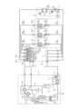
- FIG. 13 is a circuit diagram showing an example of a refrigeration cycle apparatus 100 according to the third embodiment.
- the user side units C1, C2, C3 and the heat medium converter D are connected in parallel to the relay unit B.
- the first pipe 40d of the heat medium converter D is connected to the first branch 10
- the second pipe 41d of the heat medium converter D is connected to the second branch 11.
- this is the same as in the second embodiment in that the heat medium converter D is connected to the circuit in parallel with the heat source unit A and the user side unit C.
- FIG. 14 is an explanatory diagram of the refrigerant flow when the refrigeration cycle apparatus 100 according to embodiment 3 is in full cooling operation.
- FIG. 15 is an explanatory diagram of the refrigerant flow when the refrigeration cycle apparatus 100 according to embodiment 3 is in full heating operation.
- FIG. 16 is an explanatory diagram of the refrigerant flow when the refrigeration cycle apparatus 100 according to embodiment 3 is in cooling-dominated operation.
- FIG. 17 is an explanatory diagram of the refrigerant flow when the refrigeration cycle apparatus 100 according to embodiment 3 is in heating-dominated operation.
- the refrigerant flow in each operation mode of the refrigeration cycle apparatus 100 according to embodiment 3 is the same as the refrigerant flow in each operation mode of embodiment 3.
- the heat medium converter D of the refrigeration cycle device 100 includes a first branch 10 connected to a plurality of first pipes 40 extending from each of the heat exchanger 5c of the heat medium converter C and the heat exchanger 30 of the heat medium converter D, and a second branch 11 connected to a plurality of second pipes 41 extending from each of the flow control device 4c of the heat medium converter C and the refrigerant flow control device 4d of the heat medium converter D.
- the refrigeration cycle apparatus 100 according to embodiment 3 can heat or cool the refrigerant using the heat or cold of the external heat source E by the heat medium converter D, and can use the external heat source E to assist the heat source side heat exchanger 3.
- the refrigeration cycle apparatus 100 according to embodiment 3 has the advantage that the user side unit C and the heat medium converter D are connected to the relay unit B in a similar structure, and the method of connection to the refrigeration cycle circuit can be appropriately selected depending on the type or location of the external heat source E to be used.
- the first to third embodiments of the present disclosure have been described.
- the first to third embodiments are merely examples of the refrigeration cycle device 100, and may be combined with other known technologies.
- the configuration of the refrigeration cycle device 100 may be partially omitted or modified without departing from the gist of the present disclosure.
- the refrigeration cycle device 100 includes the range of design modifications and application variations that would normally be made by a person skilled in the art, without departing from the technical concept thereof.
Landscapes
- Engineering & Computer Science (AREA)
- Physics & Mathematics (AREA)
- Mechanical Engineering (AREA)
- Thermal Sciences (AREA)
- General Engineering & Computer Science (AREA)
- Chemical & Material Sciences (AREA)
- Combustion & Propulsion (AREA)
- Other Air-Conditioning Systems (AREA)
Abstract
Un dispositif à cycle frigorifique selon la présente divulgation comprend : une machine source de chaleur ayant un compresseur qui comprime un fluide frigorigène, un échangeur de chaleur côté source de chaleur, et un premier dispositif de commutation de trajet d'écoulement qui commute une connexion entre l'échangeur de chaleur côté source de chaleur et un côté aspiration ou un côté évacuation du compresseur ; un tuyau de gaz haute pression qui est connecté au côté évacuation du compresseur et à travers lequel le fluide frigorigène s'écoule hors de la machine source de chaleur ; un tuyau de gaz basse pression qui est connecté au côté aspiration du compresseur et à travers lequel le fluide frigorigène s'écoule dans la machine source de chaleur ; une unité côté utilisation qui a un échangeur de chaleur côté utilisation et un dispositif de commande de débit côté utilisation qui commande le débit du fluide frigorigène s'écoulant à travers l'échangeur de chaleur côté utilisation ; une unité de relais de milieu caloporteur ayant un échangeur de chaleur inter-milieu caloporteur qui échange de la chaleur entre le fluide frigorigène et un milieu caloporteur qui transporte de la chaleur à partir d'une source de chaleur externe ; et un tuyau de liquide qui est connecté entre l'unité côté utilisation et la machine source de chaleur et dans lequel s'écoule le fluide frigorigène dont au moins une partie est dans un état liquide. L'unité côté utilisation est configurée de telle sorte que l'échangeur de chaleur côté utilisation peut être sélectivement connecté au tuyau de gaz haute pression ou au tuyau de gaz basse pression, le dispositif de commande de débit côté utilisation est connecté au tuyau de liquide, et l'échangeur de chaleur inter-milieu caloporteur est connecté à au moins le tuyau de liquide et se substitue à la fonction de l'échangeur de chaleur côté source de chaleur, ou aide celle-ci.
Priority Applications (1)
| Application Number | Priority Date | Filing Date | Title |
|---|---|---|---|
| PCT/JP2023/020818 WO2024252472A1 (fr) | 2023-06-05 | 2023-06-05 | Dispositif à cycle frigorifique |
Applications Claiming Priority (1)
| Application Number | Priority Date | Filing Date | Title |
|---|---|---|---|
| PCT/JP2023/020818 WO2024252472A1 (fr) | 2023-06-05 | 2023-06-05 | Dispositif à cycle frigorifique |
Publications (1)
| Publication Number | Publication Date |
|---|---|
| WO2024252472A1 true WO2024252472A1 (fr) | 2024-12-12 |
Family
ID=93795149
Family Applications (1)
| Application Number | Title | Priority Date | Filing Date |
|---|---|---|---|
| PCT/JP2023/020818 Ceased WO2024252472A1 (fr) | 2023-06-05 | 2023-06-05 | Dispositif à cycle frigorifique |
Country Status (1)
| Country | Link |
|---|---|
| WO (1) | WO2024252472A1 (fr) |
Citations (5)
| Publication number | Priority date | Publication date | Assignee | Title |
|---|---|---|---|---|
| JP2001165546A (ja) * | 1999-12-07 | 2001-06-22 | Nakano Refrigerators Co Ltd | ショーケース等の冷却システム及び冷却方法 |
| JP2001280747A (ja) * | 2000-03-31 | 2001-10-10 | Mitsubishi Heavy Ind Ltd | 空気調和装置 |
| WO2012077156A1 (fr) * | 2010-12-07 | 2012-06-14 | 三菱電機株式会社 | Dispositif de pompe à chaleur |
| JP2019158249A (ja) * | 2018-03-14 | 2019-09-19 | アイシン精機株式会社 | ガスエンジン駆動式空気調和装置 |
| JP2019158248A (ja) * | 2018-03-14 | 2019-09-19 | アイシン精機株式会社 | ガスエンジン駆動式空気調和装置 |
-
2023
- 2023-06-05 WO PCT/JP2023/020818 patent/WO2024252472A1/fr not_active Ceased
Patent Citations (5)
| Publication number | Priority date | Publication date | Assignee | Title |
|---|---|---|---|---|
| JP2001165546A (ja) * | 1999-12-07 | 2001-06-22 | Nakano Refrigerators Co Ltd | ショーケース等の冷却システム及び冷却方法 |
| JP2001280747A (ja) * | 2000-03-31 | 2001-10-10 | Mitsubishi Heavy Ind Ltd | 空気調和装置 |
| WO2012077156A1 (fr) * | 2010-12-07 | 2012-06-14 | 三菱電機株式会社 | Dispositif de pompe à chaleur |
| JP2019158249A (ja) * | 2018-03-14 | 2019-09-19 | アイシン精機株式会社 | ガスエンジン駆動式空気調和装置 |
| JP2019158248A (ja) * | 2018-03-14 | 2019-09-19 | アイシン精機株式会社 | ガスエンジン駆動式空気調和装置 |
Similar Documents
| Publication | Publication Date | Title |
|---|---|---|
| US9140459B2 (en) | Heat pump device | |
| CN110425764B (zh) | 换热系统及控制方法 | |
| JP2005299935A (ja) | 空気調和装置 | |
| CN113970194B (zh) | 热泵系统 | |
| JP3259273B2 (ja) | 空気調和装置 | |
| JP2001082818A (ja) | ヒートポンプシステムおよびヒートポンプシステムの据付方法 | |
| CN102753916B (zh) | 空气调节热水供给系统 | |
| EP2584285B1 (fr) | Dispositif de climatisation à réfrigération | |
| JP4258363B2 (ja) | 冷凍空調装置、冷凍空調装置の運転方法 | |
| WO2011104834A1 (fr) | Dispositif de conditionnement d'air | |
| CN215930175U (zh) | 一种制冷系统 | |
| JP2001263848A (ja) | 空気調和機 | |
| EP2159511B1 (fr) | Système de climatisation | |
| JP4270555B2 (ja) | 再熱除湿型空気調和機 | |
| JP6042037B2 (ja) | 冷凍サイクル装置 | |
| JP3511161B2 (ja) | 空気調和装置 | |
| CN113465220B (zh) | 一种制冷系统及控制方法 | |
| CN113432331B (zh) | 一种制冷系统及控制方法 | |
| CN113465218B (zh) | 一种制冷系统及控制方法 | |
| JP2006125762A (ja) | 室内機およびこれを備えた空気調和装置ならびにその運転方法 | |
| CN215930176U (zh) | 一种制冷系统 | |
| KR100744504B1 (ko) | 냉난방 시스템 | |
| JP6932551B2 (ja) | 熱交換システム及びその制御方法 | |
| WO2024252471A1 (fr) | Dispositif à cycle de réfrigération | |
| WO2024252473A1 (fr) | Dispositif à cycle de réfrigération |
Legal Events
| Date | Code | Title | Description |
|---|---|---|---|
| 121 | Ep: the epo has been informed by wipo that ep was designated in this application |
Ref document number: 23940579 Country of ref document: EP Kind code of ref document: A1 |
|
| NENP | Non-entry into the national phase |
Ref country code: DE |