WO2024252490A1 - Système de régulation de température de batteries - Google Patents
Système de régulation de température de batteries Download PDFInfo
- Publication number
- WO2024252490A1 WO2024252490A1 PCT/JP2023/020866 JP2023020866W WO2024252490A1 WO 2024252490 A1 WO2024252490 A1 WO 2024252490A1 JP 2023020866 W JP2023020866 W JP 2023020866W WO 2024252490 A1 WO2024252490 A1 WO 2024252490A1
- Authority
- WO
- WIPO (PCT)
- Prior art keywords
- flow path
- temperature
- heat
- unit
- battery
- Prior art date
- Legal status (The legal status is an assumption and is not a legal conclusion. Google has not performed a legal analysis and makes no representation as to the accuracy of the status listed.)
- Ceased
Links
Images



Classifications
-
- H—ELECTRICITY
- H01—ELECTRIC ELEMENTS
- H01M—PROCESSES OR MEANS, e.g. BATTERIES, FOR THE DIRECT CONVERSION OF CHEMICAL ENERGY INTO ELECTRICAL ENERGY
- H01M10/00—Secondary cells; Manufacture thereof
- H01M10/60—Heating or cooling; Temperature control
- H01M10/61—Types of temperature control
- H01M10/617—Types of temperature control for achieving uniformity or desired distribution of temperature
-
- H—ELECTRICITY
- H01—ELECTRIC ELEMENTS
- H01M—PROCESSES OR MEANS, e.g. BATTERIES, FOR THE DIRECT CONVERSION OF CHEMICAL ENERGY INTO ELECTRICAL ENERGY
- H01M10/00—Secondary cells; Manufacture thereof
- H01M10/42—Methods or arrangements for servicing or maintenance of secondary cells or secondary half-cells
- H01M10/48—Accumulators combined with arrangements for measuring, testing or indicating the condition of cells, e.g. the level or density of the electrolyte
- H01M10/486—Accumulators combined with arrangements for measuring, testing or indicating the condition of cells, e.g. the level or density of the electrolyte for measuring temperature
-
- H—ELECTRICITY
- H01—ELECTRIC ELEMENTS
- H01M—PROCESSES OR MEANS, e.g. BATTERIES, FOR THE DIRECT CONVERSION OF CHEMICAL ENERGY INTO ELECTRICAL ENERGY
- H01M10/00—Secondary cells; Manufacture thereof
- H01M10/60—Heating or cooling; Temperature control
- H01M10/61—Types of temperature control
- H01M10/613—Cooling or keeping cold
-
- H—ELECTRICITY
- H01—ELECTRIC ELEMENTS
- H01M—PROCESSES OR MEANS, e.g. BATTERIES, FOR THE DIRECT CONVERSION OF CHEMICAL ENERGY INTO ELECTRICAL ENERGY
- H01M10/00—Secondary cells; Manufacture thereof
- H01M10/60—Heating or cooling; Temperature control
- H01M10/61—Types of temperature control
- H01M10/615—Heating or keeping warm
-
- H—ELECTRICITY
- H01—ELECTRIC ELEMENTS
- H01M—PROCESSES OR MEANS, e.g. BATTERIES, FOR THE DIRECT CONVERSION OF CHEMICAL ENERGY INTO ELECTRICAL ENERGY
- H01M10/00—Secondary cells; Manufacture thereof
- H01M10/60—Heating or cooling; Temperature control
- H01M10/62—Heating or cooling; Temperature control specially adapted for specific applications
- H01M10/625—Vehicles
-
- H—ELECTRICITY
- H01—ELECTRIC ELEMENTS
- H01M—PROCESSES OR MEANS, e.g. BATTERIES, FOR THE DIRECT CONVERSION OF CHEMICAL ENERGY INTO ELECTRICAL ENERGY
- H01M10/00—Secondary cells; Manufacture thereof
- H01M10/60—Heating or cooling; Temperature control
- H01M10/63—Control systems
-
- H—ELECTRICITY
- H01—ELECTRIC ELEMENTS
- H01M—PROCESSES OR MEANS, e.g. BATTERIES, FOR THE DIRECT CONVERSION OF CHEMICAL ENERGY INTO ELECTRICAL ENERGY
- H01M10/00—Secondary cells; Manufacture thereof
- H01M10/60—Heating or cooling; Temperature control
- H01M10/63—Control systems
- H01M10/633—Control systems characterised by algorithms, flow charts, software details or the like
-
- H—ELECTRICITY
- H01—ELECTRIC ELEMENTS
- H01M—PROCESSES OR MEANS, e.g. BATTERIES, FOR THE DIRECT CONVERSION OF CHEMICAL ENERGY INTO ELECTRICAL ENERGY
- H01M10/00—Secondary cells; Manufacture thereof
- H01M10/60—Heating or cooling; Temperature control
- H01M10/63—Control systems
- H01M10/637—Control systems characterised by the use of reversible temperature-sensitive devices, e.g. NTC, PTC or bimetal devices; characterised by control of the internal current flowing through the cells, e.g. by switching
-
- H—ELECTRICITY
- H01—ELECTRIC ELEMENTS
- H01M—PROCESSES OR MEANS, e.g. BATTERIES, FOR THE DIRECT CONVERSION OF CHEMICAL ENERGY INTO ELECTRICAL ENERGY
- H01M10/00—Secondary cells; Manufacture thereof
- H01M10/60—Heating or cooling; Temperature control
- H01M10/65—Means for temperature control structurally associated with the cells
- H01M10/655—Solid structures for heat exchange or heat conduction
- H01M10/6556—Solid parts with flow channel passages or pipes for heat exchange
-
- H—ELECTRICITY
- H01—ELECTRIC ELEMENTS
- H01M—PROCESSES OR MEANS, e.g. BATTERIES, FOR THE DIRECT CONVERSION OF CHEMICAL ENERGY INTO ELECTRICAL ENERGY
- H01M10/00—Secondary cells; Manufacture thereof
- H01M10/60—Heating or cooling; Temperature control
- H01M10/65—Means for temperature control structurally associated with the cells
- H01M10/656—Means for temperature control structurally associated with the cells characterised by the type of heat-exchange fluid
- H01M10/6567—Liquids
- H01M10/6568—Liquids characterised by flow circuits, e.g. loops, located externally to the cells or cell casings
-
- H—ELECTRICITY
- H01—ELECTRIC ELEMENTS
- H01M—PROCESSES OR MEANS, e.g. BATTERIES, FOR THE DIRECT CONVERSION OF CHEMICAL ENERGY INTO ELECTRICAL ENERGY
- H01M2220/00—Batteries for particular applications
- H01M2220/20—Batteries in motive systems, e.g. vehicle, ship, plane
-
- Y—GENERAL TAGGING OF NEW TECHNOLOGICAL DEVELOPMENTS; GENERAL TAGGING OF CROSS-SECTIONAL TECHNOLOGIES SPANNING OVER SEVERAL SECTIONS OF THE IPC; TECHNICAL SUBJECTS COVERED BY FORMER USPC CROSS-REFERENCE ART COLLECTIONS [XRACs] AND DIGESTS
- Y02—TECHNOLOGIES OR APPLICATIONS FOR MITIGATION OR ADAPTATION AGAINST CLIMATE CHANGE
- Y02E—REDUCTION OF GREENHOUSE GAS [GHG] EMISSIONS, RELATED TO ENERGY GENERATION, TRANSMISSION OR DISTRIBUTION
- Y02E60/00—Enabling technologies; Technologies with a potential or indirect contribution to GHG emissions mitigation
- Y02E60/10—Energy storage using batteries
Definitions
- the present invention relates to a battery temperature regulation system.
- Electric vehicles are equipped with many battery modules to supply power to various electronic devices such as drive motors, electric actuators, and sensors.
- Overheating of the battery not only affects the battery's life and usable time, but also its safety.
- the internal resistance of the battery increases, causing a decrease in battery performance and, in some cases, even damage. For this reason, it is necessary to manage the installed battery so that it maintains an appropriate temperature state.
- Patent Documents 1 and 2 show an invention as a device for performing such temperature management, in which multiple cooling objects are arranged in parallel in a flow path, and a fixed valve or a variable valve is used to adjust the pressure difference in the flow path through which the heat medium (refrigerant, coolant, etc.) passes, thereby making the flow rate of the heat medium flowing through the cooling objects equal.
- Patent Document 3 also shows a cooling system that controls the operation of the variable valve to control the distribution of the flow rate and performs even cooling.
- the batteries installed in electric vehicles supply power to various operational and operation control devices, and as each is used under different conditions in response to the requirements of the devices they are powering, each battery generates heat differently. As a result, it is necessary to manage and adjust the temperature of each battery individually.
- the present invention was made in consideration of these problems, and aims to provide a battery temperature adjustment system that can individually manage the temperature of each battery in a plurality of batteries and adjust the temperature range for each battery appropriately.
- the present invention provides a system for adjusting the temperature of multiple batteries, comprising a heat medium, which is a fluid that transports heat, a circulation flow path through which the heat medium circulates, multiple branch flow paths that branch off in parallel from the circulation flow path and rejoin the circulation flow path, a pumping device that pumps the heat medium in the circulation flow path, multiple heat exchange units that are provided in the multiple branch flow paths, respectively, and through which the multiple batteries exchange heat with the heat medium, multiple temperature detection units that are provided in the multiple branch flow paths, respectively, and detect the temperatures of the multiple batteries, multiple control valves that are provided in the multiple branch flow paths, respectively, and are capable of controlling the flow rate of the heat medium, and a control unit that uses a heat supply device connected to the circulation flow path that heats or cools the heat medium, to control at least the multiple control valves and the pumping device in accordance with the temperature detected by the temperature detection unit.
- a heat medium which is a fluid that transports heat
- a circulation flow path through which the heat medium circulates
- the heat supply device may be configured to have a cooling section that cools the heat medium and a heating section that heats the heat medium, a cooling flow path that branches off from the circulation flow path and passes through the cooling section, a heating flow path that passes through the heating section, and a switching control valve in the circulation flow path that can control switching from the circulation flow path to a flow path that passes through the cooling flow path or from the circulation flow path to a flow path that passes through the heating flow path, and the control section may be configured to control the switching of the switching control valve.
- control unit may have a comparison unit that compares a predetermined threshold value with the temperature detected by the temperature detection unit, and a command unit that transmits a control signal to command the control according to the comparison result of the comparison unit.
- the multiple batteries may be vehicle batteries.
- the battery temperature adjustment system is configured such that a heat exchange unit, a temperature detection unit, and a control valve are provided in each of a plurality of branch flow paths branched off from a circulation flow path, a pressure delivery device that uses a heat supply device to heat or cool the heat medium, and a control unit that performs control.
- the pressure delivery device is controlled to pressure delivery of the heat medium heated or cooled using the heat supply device according to the temperature of each battery detected by the temperature detection unit, and the control unit controls the control valve to adjust the flow rate, thereby enabling temperature management for each of the multiple batteries.
- Temperature adjustment can also be performed when the cooling or heating requirements of each battery change due to different usage conditions.
- the control unit may also control the heat exchange unit if temperature adjustment control using the heat exchange unit is possible.
- the heat supply device has a cooling section that cools the heat medium and a heating section that heats the heat medium, and is configured with a switching control valve that can switch between a cooling flow path that passes through the cooling section and a heating flow path that passes through the heating section.
- the control section is configured to control the switching of the flow path of the switching control valve, making it possible to cool or heat the battery. This allows the temperature of the battery to be adjusted.
- the control unit has a comparison unit and a command unit, and can compare a predetermined threshold value with the temperature detected by the temperature detection unit, and change the control of the pumping device, control valve, switching control valve, etc., controlled by the control unit based on the comparison result.
- the predetermined threshold value is a temperature value set for the optimum temperature range for battery use, and it is preferable to set temperatures above and below this range as threshold values in advance. In other words, it is preferable to set a threshold value for starting temperature adjustment by cooling and a threshold value for starting temperature adjustment by heating.
- the battery is preferably a vehicle battery. This allows the battery to be adjusted to an optimal temperature range even when used under different operating conditions, such as in a vehicle drive motor, electronic device, or electric actuator. This also allows the battery's usage time relative to charging to be extended.
- FIG. 1 is a schematic diagram showing an example in which a battery temperature regulation system according to the present invention is applied to an electric vehicle.
- 1 is a configuration diagram showing a battery temperature regulating system according to a first embodiment
- 2 is a block diagram illustrating a control mechanism of the battery temperature regulating system according to the first embodiment.
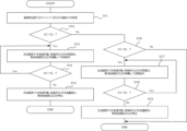
- FIG. 4 is a flowchart illustrating control of the battery temperature regulating system according to the first embodiment.
- FIG. 11 is a configuration diagram showing a battery temperature regulating system according to a second embodiment.
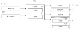
- FIG. 11 is a block diagram illustrating a control mechanism of a battery temperature regulating system according to a second embodiment.
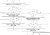
- 10 is a flowchart illustrating control of a battery temperature regulating system according to a second embodiment.
- FIG. 1 shows the main components of the electric vehicle 200 related to the battery temperature regulation system SYS, but does not show all of the configuration of the electric vehicle 200.
- the electric vehicle 200 includes multiple batteries BT1 to BTn, a battery temperature regulation system SYS according to the present embodiment that manages the temperatures of the batteries BT1 to BTn, a heat supply device 202, and an electronic control unit ECU.
- the electric vehicle 200 drives a drive motor using electricity stored in multiple batteries BT1 to BTn (hereinafter collectively referred to as batteries BT).
- the drive force of the drive motor is also controlled by controlling the voltage.
- the electricity stored in the battery BT is also used to drive other electric actuators and electronic devices.
- the temperature of the batteries BT1 to BTn is managed using the battery temperature regulation system SYS according to the present embodiment.
- the batteries BT1 to BTn each have an optimum temperature range for battery operation depending on the type, and stable operation is guaranteed within that temperature range. It is preferable that the control unit TCU, which will be described later, sets a threshold value for determining control for heating or cooling, determined based on the upper and lower limits of the temperature range of the batteries BT1 to BTn. If the upper limit of this temperature range is exceeded and the battery becomes overheated, this leads to the battery's lifespan and deterioration. In addition, in a low temperature state below the lower limit of the temperature range, the internal resistance of the battery increases, and performance decreases.
- the battery in a quick charge in a cold region, in an environment where the battery temperature is 30 to 50°C, the battery can be restored to 30 to 40% of full charge with 30 minutes of charging, whereas the charge amount decreases at 10°C or less, and further decreases significantly at 0°C or less, and the same 30 minutes of charging only restores less than 10%. In this way, the charging ability decreases as the temperature decreases.
- the batteries BT1 to BTn may each be a different type of battery, and in this case it is preferable to set a threshold value based on the temperature range corresponding to each type.
- the electronic control unit ECU communicates with various electronic devices installed in the electric vehicle 200, and controls the engine, transmission, brakes, and other electronic devices through a combination of hardware and software.
- This electronic control unit ECU may be an in-vehicle ECU (Electric Control Unit).
- the electronic control unit ECU communicates with the control unit TCU (described later) via wired or wireless communication.
- the heat supply device 202 is a device capable of adjusting the temperature inside the electric vehicle 200, and is, for example, an electric fan, a radiator, or a semiconductor ceramic heater such as a PTC (Positive Temperature Coefficient) heater.
- the electric fan rotates with the air flow while the vehicle is running, and the air flow caused by the rotation cools the object.
- the radiator is a device that flows a cooled fluid inside and exchanges heat with the surrounding air or fluid, thereby cooling the object.
- the PTC heater is a heating device that is made by mixing highly conductive particles such as semiconductor particles and carbon particles, and is designed to change the ease of electrical flow depending on the temperature.
- Such a heat supply device 202 capable of heating or cooling is used as a device that heats or cools the heat medium 10 described later in the battery temperature adjustment system SYS according to this embodiment.
- the heat medium 10 is a fluid that is heated or cooled by the heat supply device 202, and transfers its heat by moving itself.
- the heat medium 10 circulates through the circulation flow path 12 and the branch flow path 13 described below, and exchanges heat with the batteries BT1 to BTn in the heat exchange sections HX1 to HXn.
- the heated heat medium 10 provides heat to the battery BT, thereby heating the target battery.
- the cooled heat medium 10 removes heat from the battery BT, thereby cooling the battery.
- a heat medium 10, LLC Long Life Coolant
- the fluid be one that can be used for both. It is also desirable that the material does not corrode the material that constitutes the flow path.
- the pumping device 11 is installed in the circulation flow path 12 and pumps the heat medium 10 in a fixed direction through the circulation flow path to form a flow.
- the pumping device 11 can control the pressure during pumping and the pumping speed of the heat medium 10. This control is performed by the control unit TCU.
- the position of the pumping device 11 in FIG. 2 is an example and can be changed as appropriate.
- An electric water pump can be used as the pumping device 11.
- the circulation flow path 12 is a circulation flow path through which the heat medium 10 flows.
- a plurality of branch flow paths 13(1) to 13(n) branch off in parallel from the circulation flow path 12, and the plurality of branch flow paths 13(1) to 13(n) merge again and connect to the circulation flow path 12.
- a heat supply device 202 is installed midway along the circulation flow path 12, and is installed so that the heat medium 10 can be cooled or heated by the heat supply device 202.
- the heat supply device 202 has a cooling section 202a and a heating section 202b, it is preferable to have a switching control valve RV, which will be described later, upstream of the heat supply device 202.
- Branch flow paths 13(1) to 13(n) branch off in parallel from circulation flow path 12 and merge again to connect to circulation flow path 12.
- At least one heat exchange unit HX1 to HXn, one temperature detection unit T1 to Tn, and one control valve SV1 to SVn are installed in each of the multiple branch flow paths 13(1) to 13(n).
- branch flow path 13(1) is installed with a heat exchange unit HX1, a temperature detection unit T1, and a control valve SV1. This makes it possible to form flow paths for individually detecting the temperatures of batteries BT1 to BTn and individually performing heat exchange.
- At least one heat exchange unit HX1 to HXn (hereinafter, when multiple units are referred to collectively, they are also referred to as heat exchange unit HX) is provided on each of the branch flow paths 13(1) to 13(n).
- the heat exchange unit HX and the battery BT are connected and installed so that they can exchange heat with each other.
- the heat medium 10 is installed so that it can exchange heat with the heat exchange unit HX by passing through the branch flow path 13.
- the heat exchange unit HX is formed from a material with high thermal conductivity.
- At least one temperature detection unit T1 to Tn (hereinafter, when multiple units are referred to collectively, they are also referred to as temperature detection unit T) is installed in each of the branch flow paths 13(1) to 13(n), and detects the temperature of the batteries BT1 to BTn based on the temperature of the heat medium 10 after passing through the heat exchange units HX1 to HXn.
- the temperature detection unit T may directly detect the temperature of the batteries BT1 to BTn. Alternatively, it may detect both the temperature of the batteries BT1 to BTn and the temperature of the heat medium 10 after passing through the heat exchange units HX1 to HXn, and detect the amount of change.
- the temperature of the temperature detection units T1 to Tn is monitored by the control unit TCU while comparing it with a threshold value described later. Temperature sensors such as thermistors can be used as such temperature detection units T1 to Tn.
- At least one control valve SV1 to SVn (hereinafter also referred to as control valve SV) is provided in each of the multiple branch flow paths 13(1) to 13(n).
- the control valve SV can adjust the flow rate of the heat medium 10 from upstream to downstream and open and close the flow path by moving the valve body.
- the valve body of the control valve SV is controlled by the control unit TCU.
- a solenoid valve electromagnettic valve
- the control unit TCU controls at least the pressure-feeding device 11 and the control valves SV1 to SVn in response to temperature information received from the temperature detection units T1 to Tn. If a switching control valve RV is provided, it controls the pressure-feeding device 11, the control valves SV1 to SVn, and the switching control valve RV. It is preferable to configure the control unit TCU to centrally control the control of the electronic devices included in the battery temperature adjustment system SYS.
- the control unit TCU may also control the heat supply unit 202. If the heat exchange units HX1 to HXn are controllable, the heat exchange units HX1 to HXn may also be controlled by the control unit TCU.
- the control unit TCU is composed of a comparison unit 30 and a command unit 31.
- the comparison unit 30 compares the temperature measured by the temperature detection units T1 to Tn with the cooling threshold temperature Ta or the heating threshold temperature Tb.
- the cooling threshold temperature Ta is a value determined based on the upper limit of the optimum temperature range for operating the battery BT
- the heating threshold temperature Tb is a temperature determined based on the lower limit of the optimum temperature range for operating the battery BT.
- the comparison unit 30 compares the temperature from the temperature detection unit T with the cooling threshold temperature Ta and the heating threshold temperature Tb to determine which is larger. If the temperature exceeds the cooling threshold temperature Ta, it determines that a cooling operation of the battery BT should be performed, and if the temperature exceeds the heating threshold temperature Tb, it determines that a heating operation of the battery BT should be performed. If there are multiple types of batteries, it is preferable to set threshold temperatures Ta and Tb for the appropriate temperature range for each type of battery.
- the control unit TCU has a command unit 31 that transmits control signals to control each mechanism based on the judgment made by the comparison unit 30.
- the command unit 31 transmits a control signal to each control target according to the judgment of the comparison unit 30.
- the signal lines that transmit the control signals are indicated as L1, L2(1)-L2(n), L3(1)-L3(n), L4, L5, L5a, and L5b.
- the control unit TCU is preferably configured to perform two-way wired or wireless communication with the electronic control unit ECU of the electric vehicle 200.
- the electronic control unit ECU can receive information such as the battery temperature and use it for other controls. Information can also be received from the electronic control unit ECU and used for controlling the control unit TCU.
- wired CAN Controller Area Network
- the switching control valve RV is a control valve that can switch to multiple flow paths using a valve body, and the switching is controlled by the control unit TCU.
- the heat supply device 202 installed in the circulation flow path 12 has a cooling section 202a and a heating section 202b independently, it is preferable that it is configured to have a cooling flow path 14a that branches off from the circulation flow path and passes through the cooling section 202a, and a heating flow path 14b that passes through the heating section 202b.
- the switching control valve RV is configured to be able to switch the flow path to either the cooling flow path or the heating flow path.
- a rotary valve can be used as the switching control valve RV.
- the battery temperature adjustment system SYS heats and cools the heat medium 10 using the heat supply device 202 provided in the electric vehicle 200 described above.
- the heat supply device 202 may have a cooling section 202a that performs cooling and a heating section 202b that performs heating, which are independent of each other.
- the heat supply device 202 may also be a device that can perform both heating and cooling.
- the heat supply device 202 is preferably controlled by the control unit TCU.
- the battery temperature regulation system SYS(1) according to the first embodiment will be described with reference to the configuration diagram of Fig. 2.
- the battery temperature regulation system SYS(1) according to the first embodiment includes a heat medium 10 (not shown), a pressure-feeding device 11, a circulation flow path 12, a plurality of branch flow paths 13(1) to 13(n), a plurality of heat exchange units HX1 to HXn, a plurality of temperature detection units T1 to Tn, a plurality of control valves SV1 to SVn, and a control unit TCU.
- the control unit TCU includes a comparison unit 30 and a command unit 31, and uses a heat supply unit 202 to regulate the temperatures of the batteries BT1 to BTn.
- the heat medium 10 branches from the circulation flow path 12 into a number of branch flow paths 13(1) to 13(n), then merges back into the circulation flow path 12 and circulates.
- a heat supply device 202 is installed on the circulation flow path 12, and the heat medium 10 is cooled or heated.
- the comparison unit 30 has a cooling threshold temperature Ta at which cooling control begins and a heating threshold temperature Tb at which heating control begins, for the appropriate temperature range for the batteries BT1 to BTn.
- a storage unit 20 is installed in the circulation flow path 12, and stores and replenishes the heat medium 10.
- the storage unit 20 is a tank or the like.
- the heat medium 10 is pumped from the heat supply device 202 through the circulation flow path 12 by the pumping device 11, and circulates in the direction indicated by the arrow in FIG. 2, that is, from the circulation flow path 12 through the branch flow path 13 and back to the circulation flow path 12.
- FIG. 3 is a block diagram showing a control mechanism by the control unit TCU of the battery temperature adjustment system SYS(1) according to the first embodiment.
- the control unit TCU controls the pressure transfer device 11, the control valves SV1 to SVn, and the heat supply device 202 according to the temperatures detected by the temperature detection units T1 to Tn.
- the control unit TCU also communicates with the electronic control unit ECU to exchange information with each other.
- control signals are sent using signal lines L1, L2(1) to L2(n), L3(1) to L3(n), and L5 shown in Figure 2.
- Signal line L1 is a signal line for sending control signals to the pumping device 11, signal lines L2(1) to L2(n) to temperature detection units T1 to Tn, signal lines L3(1) to L3(n) to control valves SV1 to SVn, and signal line L5 to the heat supply device 202.
- the following describes an example of a method for adjusting the temperature of the battery by the control unit TCU in the battery temperature adjustment system SYS(1) according to the first embodiment described above.
- FIG. 4 is a flowchart showing the flow of temperature adjustment for battery BT2 in the first embodiment.
- the battery temperature adjustment system SYS(1) controls each of the batteries BT1 to BTn as shown in FIG. 4, but here, battery BT2 will be used for the explanation.
- the pumping device 11 operates at a low speed or is stopped by a control signal from the control unit TCU, and the control valves SV1 to SVn each pass a low amount of water.
- the heat medium 10 passes from the circulation flow path 12 through the heat supply device 202, passes through the branch flow paths 13(1) to 13(n), and returns to the circulation flow path 12 and circulates. At this time, the heat supply device 202 is not operating. Note that the pumping device 11 can be stopped depending on the temperature state of the battery BT to save electrical energy.
- the control unit TCU uses the comparison unit 30 to compare whether the detected temperatures received from the temperature detection units T1 to Tn via signal lines L2(1) to L2(n) are in a temperature range greater than the heating threshold temperature Tb and less than the cooling threshold temperature Ta, following the flow shown in FIG. 4, and controls each mechanism via the command unit 31 via signal lines L1, L3(1) to L3(n), etc.
- the control unit TCU receives information on the temperature X1 of the battery BT2 from the temperature detection unit T2 (step ST1), compares it with the cooling threshold temperature Ta (step ST2), and if it is determined that X1>Ta, operates the pumping device 11 at high speed, controls the control valve SV2 to be fully open, and operates the heat supply device 202 to start the cooling operation (step ST3). Then, the comparison unit 30 compares the temperature X1 of the battery BT2 with Ta (step ST4).
- Steps ST3 and ST4 are repeated, and when the temperature X1 falls below Ta and Tb ⁇ X1 ⁇ Ta is satisfied, the pumping device 11 is operated at low speed, the flow rate of the control valve SV2 is controlled to be low, and the heat supply device 202 is stopped (step ST5).
- the comparison unit 30 compares it with the heating threshold temperature Tb (step ST6). If it is determined that X1 ⁇ Tb, the pressure-feeding device 11 is operated at high speed, the control valve SV2 is controlled to be fully open, and the heat supply device 202 is operated to start the heating operation (step ST7). Then, the comparison unit 30 compares the temperature X1 of the battery BT2 with Tb (step ST8).
- Steps ST7 and ST8 are repeated, and when the temperature X1 exceeds Tb and Tb ⁇ X1 ⁇ Ta is satisfied, the pressure-feeding device 11 is operated at low speed, the flow rate of the control valve SV2 is controlled to be low, and the heat supply device 202 is stopped (step ST9).
- the temperature can be adjusted individually for each battery.
- the battery temperature adjustment system SYS(2) according to the second embodiment will be described with reference to the configuration diagram of FIG. 5.
- the battery temperature adjustment system SYS(2) according to the second embodiment includes a heat medium 10 (not shown), a pressure-feeding device 11, a circulation flow path 12, a plurality of branch flow paths 13(1) to 13(n), a plurality of heat exchanger units HX1 to HXn, a plurality of temperature detector units T1 to Tn, a plurality of control valves SV1 to SVn, a switching control valve RV, and a control unit TCU.
- the control unit TCU includes a comparison unit 30 and a command unit 31, and adjusts the temperature of the batteries BT1 to BTn using a heat supply device 202.
- the heat supply device 202 includes a cooling unit 202a and a heating unit 202b, and includes a cooling flow path 14a that branches off from the circulation flow path 12 and passes through the cooling unit 202a, and a heating flow path 14b that branches off from the circulation flow path 12 and passes through the heating unit 202b.
- the heat medium 10 branches from the circulation flow path 12 into a plurality of branch flow paths 13(1) to 13(n), rejoins the circulation flow path 12, passes through the cooling flow path 14a or the heating flow path 14b, and rejoins the circulation flow path 12 to circulate.
- a heat supply device 202 is installed on the circulation flow path 12, and the heat medium 10 is cooled or heated.
- a cooling threshold temperature Ta at which cooling control is started and a heating threshold temperature Tb at which heating control is started are set, and the comparison unit 30 has the cooling threshold temperature Ta and the heating threshold temperature Tb.
- a storage unit 20 is installed on the circulation flow path 12, and stores and replenishes the heat medium 10.
- the storage unit 20 is a tank or the like.
- the heat supply device 202 in the first embodiment has a cooling section 202a and a heating section 202b, and is configured to adjust the temperature by switching the flow path between cooling and heating using a switching control valve RV, and a description that overlaps with the first embodiment will be omitted. Also, parts with the same symbols as in the first embodiment have the same functions, and a description that overlaps with the first embodiment will be omitted.
- the battery temperature adjustment system SYS(2) has, as in the first embodiment, a circulation flow path 12 and branch flow paths 13(1) to 13n that branch from the circulation flow path 12 in parallel and merge again with the circulation flow path 12.
- the heat medium 10 is compressed by the compression device 11 into the circulation flow path 12 and circulated. At this time, during cooling, it circulates through the cooling section 202a, and during heating, it circulates through the heating section 202b.
- the circulation flow path 12 After leaving the heat supply device 202, it branches from the circulation flow path 12 into branch flow paths 13(1) to 13(n), merges again with the circulation flow path 12, and circulates back to the circulation flow path 12 through the cooling flow path 14a.
- During heating after leaving the heat supply device 202, it branches from the circulation flow path 12 into branch flow paths 13(1) to 13(n), merges again with the circulation flow path 12, and circulates back to the circulation flow path 12 through the heating flow path 14b.
- FIG. 6 is a block diagram showing a control mechanism by the control unit TCU of the battery temperature adjustment system SYS(2) according to the second embodiment.
- control unit TCU controls the pressure-feeding device 11, the control valves SV1 to SVn, the switching control valve RV, the cooling unit 202a, and the heating unit 202b according to the temperatures detected by the temperature detection units T1 to Tn.
- the control unit TCU also communicates with the electronic control unit ECU to exchange information with each other. During control, control signals are sent using the signal lines L1, L2(1)-L2(n), L3(1)-L3(n), L4, L5a, and L5b shown in FIG. 5.
- the signal line L1 is a signal line for sending control signals to the pumping device 11, the signal lines L2(1)-L2(n) are temperature detection units T1-Tn, the signal lines L3(1)-L3(n) are control valves SV1-SVn, the signal line L4 is a signal line for sending control signals to the switching control valve RV, the signal line L5a is a signal line for sending control signals to the cooling unit 202a, and the signal line L5b is a signal line for sending control signals to the heating unit 202b.
- the following describes an example of a method for adjusting the temperature of the battery by the control unit TCU in the battery temperature adjustment system SYS(2) according to the second embodiment described above.
- FIG. 7 is a flowchart showing the flow of temperature adjustment for the battery BT2 in the second embodiment.
- the battery temperature adjustment system SYS(2) controls each of the batteries BT1 to BTn as shown in FIG. 7, but here, the battery BT2 is used for the explanation.
- the pumping device 11 operates at a low speed or is stopped by a control signal from the control unit TCU, the control valves SV1 to SVn each pass water at a low rate, and the switching control valve RV passes water to the cooling unit 202a, forming a circulation flow path for the heat medium 10 that circulates from the circulation flow path 12 through the branch flow paths 13(1) to 13(n) via the cooling unit 202a.
- the heat supply device 202 is not operating. Note that the pumping device 11 can be stopped depending on the temperature state of the battery BT to save electrical energy.
- the control unit TCU compares whether the detected temperatures received from the temperature detection units T1 to Tn via the signal lines L2(1) to L2(n) are in a temperature range greater than the heating threshold temperature Tb and less than the cooling threshold temperature Ta, according to the flow shown in FIG. 7, and controls each mechanism via the command unit 31 via the signal lines L1, L3(1) to L3(n), L4, L5a, L5b, etc.
- control unit TCU receives information on the temperature X2 of the battery BT2 from the temperature detection unit T2 (step ST11), it compares it with the cooling threshold temperature Ta in the comparison unit 30 (step ST12). If it is determined that X2>Ta, it operates the pumping device 11 at high speed, controls the control valve SV2 to be fully open, switches the switching control valve RV to the cooling flow path 14a, and operates the cooling unit 202a to start the cooling operation (step ST13). Then, it compares the temperature X2 of the battery BT2 with Ta (step ST14).
- Steps ST13 and ST14 are repeated, and when the temperature X2 falls below Ta and Tb ⁇ X2 ⁇ Ta is satisfied, it operates the pumping device 11 at low speed, controls the flow rate of the control valve SV2 to be low, and stops the cooling unit 202a (step ST15).
- the comparison unit 30 compares it with the heating threshold temperature Tb (step ST16). If it is determined that X2 ⁇ Tb, the pumping device 11 is operated at high speed, the control valve SV2 is controlled to be fully open, the switching control valve RV is switched to the heating flow path 14b, and the heating unit 202b is operated to start the heating operation (step ST17). Then, the temperature X2 of the battery BT2 is compared with Tb (step ST18).
- Steps ST17 and ST18 are repeated, and when the temperature X2 exceeds Tb and Tb ⁇ X2 ⁇ Ta is satisfied, the pumping device 11 is operated at low speed, the flow rate of the control valve SV2 is controlled to be low, the switching control valve RV is switched to the cooling flow path 14a, and the heating unit 202b is stopped (step ST19).
- the switching control valve RV is switched to the cooling flow path 14a or the heating flow path 14b during normal operation depends on the design.
- the temperature can be adjusted individually for each battery.
- the battery temperature adjustment system configured as described above can provide a battery temperature adjustment system that can adjust the temperature of multiple batteries individually by cooling and heating, even when the cooling or heating requirements for each battery change due to different usage conditions.
Landscapes
- Engineering & Computer Science (AREA)
- Manufacturing & Machinery (AREA)
- Chemical & Material Sciences (AREA)
- Chemical Kinetics & Catalysis (AREA)
- Electrochemistry (AREA)
- General Chemical & Material Sciences (AREA)
- Automation & Control Theory (AREA)
- Secondary Cells (AREA)
- Electric Propulsion And Braking For Vehicles (AREA)
Abstract
Priority Applications (5)
| Application Number | Priority Date | Filing Date | Title |
|---|---|---|---|
| EP23940597.0A EP4723306A1 (fr) | 2023-06-05 | 2023-06-05 | Système de régulation de température de batteries |
| PCT/JP2023/020866 WO2024252490A1 (fr) | 2023-06-05 | 2023-06-05 | Système de régulation de température de batteries |
| KR1020257040272A KR20260003286A (ko) | 2023-06-05 | 2023-06-05 | 배터리 온도 조정 시스템 |
| CN202380098951.4A CN121263899A (zh) | 2023-06-05 | 2023-06-05 | 电池温度调整系统 |
| JP2025525466A JPWO2024252490A1 (fr) | 2023-06-05 | 2023-06-05 |
Applications Claiming Priority (1)
| Application Number | Priority Date | Filing Date | Title |
|---|---|---|---|
| PCT/JP2023/020866 WO2024252490A1 (fr) | 2023-06-05 | 2023-06-05 | Système de régulation de température de batteries |
Publications (1)
| Publication Number | Publication Date |
|---|---|
| WO2024252490A1 true WO2024252490A1 (fr) | 2024-12-12 |
Family
ID=93795310
Family Applications (1)
| Application Number | Title | Priority Date | Filing Date |
|---|---|---|---|
| PCT/JP2023/020866 Ceased WO2024252490A1 (fr) | 2023-06-05 | 2023-06-05 | Système de régulation de température de batteries |
Country Status (5)
| Country | Link |
|---|---|
| EP (1) | EP4723306A1 (fr) |
| JP (1) | JPWO2024252490A1 (fr) |
| KR (1) | KR20260003286A (fr) |
| CN (1) | CN121263899A (fr) |
| WO (1) | WO2024252490A1 (fr) |
Citations (6)
| Publication number | Priority date | Publication date | Assignee | Title |
|---|---|---|---|---|
| JP2013187159A (ja) * | 2012-03-09 | 2013-09-19 | Hitachi Ltd | 電池システム及びその温度制御方法 |
| WO2016088476A1 (fr) * | 2014-12-04 | 2016-06-09 | 本田技研工業株式会社 | Dispositif d'alimentation électrique de véhicule |
| JP5974492B2 (ja) | 2012-01-17 | 2016-08-23 | アイシン精機株式会社 | ハイブリッド車両の冷却システム |
| JP2020004484A (ja) * | 2018-06-25 | 2020-01-09 | 株式会社デンソー | 電池温調装置及び制御装置 |
| JP6775705B2 (ja) | 2017-07-21 | 2020-10-28 | ジン−ジン エレクトリック テクノロジーズ カンパニー リミテッド | バッテリーエネルギー貯蔵液体冷却システム用の流量均等化装置及び方法 |
| JP7138595B2 (ja) | 2019-03-22 | 2022-09-16 | 株式会社ヴァレオジャパン | 車両用バッテリーの冷却システム |
-
2023
- 2023-06-05 WO PCT/JP2023/020866 patent/WO2024252490A1/fr not_active Ceased
- 2023-06-05 CN CN202380098951.4A patent/CN121263899A/zh active Pending
- 2023-06-05 EP EP23940597.0A patent/EP4723306A1/fr active Pending
- 2023-06-05 KR KR1020257040272A patent/KR20260003286A/ko active Pending
- 2023-06-05 JP JP2025525466A patent/JPWO2024252490A1/ja active Pending
Patent Citations (6)
| Publication number | Priority date | Publication date | Assignee | Title |
|---|---|---|---|---|
| JP5974492B2 (ja) | 2012-01-17 | 2016-08-23 | アイシン精機株式会社 | ハイブリッド車両の冷却システム |
| JP2013187159A (ja) * | 2012-03-09 | 2013-09-19 | Hitachi Ltd | 電池システム及びその温度制御方法 |
| WO2016088476A1 (fr) * | 2014-12-04 | 2016-06-09 | 本田技研工業株式会社 | Dispositif d'alimentation électrique de véhicule |
| JP6775705B2 (ja) | 2017-07-21 | 2020-10-28 | ジン−ジン エレクトリック テクノロジーズ カンパニー リミテッド | バッテリーエネルギー貯蔵液体冷却システム用の流量均等化装置及び方法 |
| JP2020004484A (ja) * | 2018-06-25 | 2020-01-09 | 株式会社デンソー | 電池温調装置及び制御装置 |
| JP7138595B2 (ja) | 2019-03-22 | 2022-09-16 | 株式会社ヴァレオジャパン | 車両用バッテリーの冷却システム |
Also Published As
| Publication number | Publication date |
|---|---|
| EP4723306A1 (fr) | 2026-04-08 |
| KR20260003286A (ko) | 2026-01-06 |
| CN121263899A (zh) | 2026-01-02 |
| JPWO2024252490A1 (fr) | 2024-12-12 |
Similar Documents
| Publication | Publication Date | Title |
|---|---|---|
| CN110962529B (zh) | 车辆的热管理系统 | |
| CN110962532B (zh) | 车辆的热管理系统 | |
| JP7505176B2 (ja) | バッテリー温度管理装置 | |
| CN110962530A (zh) | 车辆的热管理系统 | |
| US12172490B2 (en) | Vehicular heat management system | |
| CN108859740B (zh) | 一种冷却系统及电动汽车 | |
| JP2004060653A (ja) | 車両の冷却加熱循環系を作動する方法 | |
| CN112448063A (zh) | 热管理系统、热管理系统的控制方法、存储介质 | |
| CN111361410B (zh) | 混合动力汽车热控制系统及控制方法 | |
| US12479271B2 (en) | Control system for thermal management and distribution | |
| CN113348117A (zh) | 混合动力车辆的冷却装置 | |
| WO2010038919A1 (fr) | Système de température uniforme pour la transmission d’un véhicule et procédé de régulation associé | |
| JP7517211B2 (ja) | 冷却システム | |
| TWI685997B (zh) | 基於半導體的車載電池溫度調節方法和溫度調節系統 | |
| JP7315296B1 (ja) | 作業機械およびその温度管理システム | |
| WO2024252490A1 (fr) | Système de régulation de température de batteries | |
| CN105840359B (zh) | 用于机动车辆的燃料供应系统的调温装置 | |
| WO2024252491A1 (fr) | Dispositif de refroidissement et chauffage de batterie | |
| CN118596778A (zh) | 换热模块、热管理系统和车辆 | |
| CN117691149A (zh) | 燃料电池热管理方法及系统 | |
| CN116691293A (zh) | 汽车热管理系统及汽车 | |
| GB2624864A (en) | Electric vehicle thermal management | |
| CN223116156U (zh) | 工程机械用集成耦合采暖系统及电动装载机 | |
| CN222629110U (zh) | 一种混合动力车辆热管理系统及车辆 | |
| CN118991349B (zh) | 车辆热管理系统、控制方法及车辆 |
Legal Events
| Date | Code | Title | Description |
|---|---|---|---|
| 121 | Ep: the epo has been informed by wipo that ep was designated in this application |
Ref document number: 23940597 Country of ref document: EP Kind code of ref document: A1 |
|
| ENP | Entry into the national phase |
Ref document number: 2025525466 Country of ref document: JP Kind code of ref document: A |
|
| ENP | Entry into the national phase |
Ref document number: 1020257040272 Country of ref document: KR Free format text: ST27 STATUS EVENT CODE: A-0-1-A10-A15-NAP-PA0105 (AS PROVIDED BY THE NATIONAL OFFICE) |
|
| WWE | Wipo information: entry into national phase |
Ref document number: 1020257040272 Country of ref document: KR |
|
| WWE | Wipo information: entry into national phase |
Ref document number: 2023940597 Country of ref document: EP |
|
| NENP | Non-entry into the national phase |
Ref country code: DE |
|
| WWP | Wipo information: published in national office |
Ref document number: 1020257040272 Country of ref document: KR |
|
| ENP | Entry into the national phase |
Ref document number: 2023940597 Country of ref document: EP Effective date: 20260105 |
|
| ENP | Entry into the national phase |
Ref document number: 2023940597 Country of ref document: EP Effective date: 20260105 |
|
| ENP | Entry into the national phase |
Ref document number: 2023940597 Country of ref document: EP Effective date: 20260105 |
|
| ENP | Entry into the national phase |
Ref document number: 2023940597 Country of ref document: EP Effective date: 20260105 |
|
| ENP | Entry into the national phase |
Ref document number: 2023940597 Country of ref document: EP Effective date: 20260105 |
|
| WWP | Wipo information: published in national office |
Ref document number: 2023940597 Country of ref document: EP |