WO2024252502A1 - Dispositif électronique - Google Patents
Dispositif électronique Download PDFInfo
- Publication number
- WO2024252502A1 WO2024252502A1 PCT/JP2023/020899 JP2023020899W WO2024252502A1 WO 2024252502 A1 WO2024252502 A1 WO 2024252502A1 JP 2023020899 W JP2023020899 W JP 2023020899W WO 2024252502 A1 WO2024252502 A1 WO 2024252502A1
- Authority
- WO
- WIPO (PCT)
- Prior art keywords
- housing
- electronic device
- fitted
- fitting
- monitor
- Prior art date
- Legal status (The legal status is an assumption and is not a legal conclusion. Google has not performed a legal analysis and makes no representation as to the accuracy of the status listed.)
- Ceased
Links
Images






Classifications
-
- H—ELECTRICITY
- H05—ELECTRIC TECHNIQUES NOT OTHERWISE PROVIDED FOR
- H05K—PRINTED CIRCUITS; CASINGS OR CONSTRUCTIONAL DETAILS OF ELECTRIC APPARATUS; MANUFACTURE OF ASSEMBLAGES OF ELECTRICAL COMPONENTS
- H05K5/00—Casings, cabinets or drawers for electric apparatus
- H05K5/02—Details
- H05K5/0204—Mounting supporting structures on the outside of casings
-
- B—PERFORMING OPERATIONS; TRANSPORTING
- B64—AIRCRAFT; AVIATION; COSMONAUTICS
- B64D—EQUIPMENT FOR FITTING IN OR TO AIRCRAFT; FLIGHT SUITS; PARACHUTES; ARRANGEMENT OR MOUNTING OF POWER PLANTS OR PROPULSION TRANSMISSIONS IN AIRCRAFT
- B64D11/00—Passenger or crew accommodation; Flight-deck installations not otherwise provided for
- B64D11/0015—Arrangements for entertainment or communications, e.g. radio, television
-
- B—PERFORMING OPERATIONS; TRANSPORTING
- B60—VEHICLES IN GENERAL
- B60R—VEHICLES, VEHICLE FITTINGS, OR VEHICLE PARTS, NOT OTHERWISE PROVIDED FOR
- B60R11/00—Arrangements for holding or mounting articles, not otherwise provided for
- B60R11/02—Arrangements for holding or mounting articles, not otherwise provided for for radio sets, television sets, telephones, or the like; Arrangement of controls thereof
- B60R11/0229—Arrangements for holding or mounting articles, not otherwise provided for for radio sets, television sets, telephones, or the like; Arrangement of controls thereof for displays, e.g. cathodic tubes
- B60R11/0235—Arrangements for holding or mounting articles, not otherwise provided for for radio sets, television sets, telephones, or the like; Arrangement of controls thereof for displays, e.g. cathodic tubes of flat type, e.g. LCD
-
- F—MECHANICAL ENGINEERING; LIGHTING; HEATING; WEAPONS; BLASTING
- F16—ENGINEERING ELEMENTS AND UNITS; GENERAL MEASURES FOR PRODUCING AND MAINTAINING EFFECTIVE FUNCTIONING OF MACHINES OR INSTALLATIONS; THERMAL INSULATION IN GENERAL
- F16F—SPRINGS; SHOCK-ABSORBERS; MEANS FOR DAMPING VIBRATION
- F16F15/00—Suppression of vibrations in systems; Means or arrangements for avoiding or reducing out-of-balance forces, e.g. due to motion
- F16F15/02—Suppression of vibrations of non-rotating, e.g. reciprocating systems; Suppression of vibrations of rotating systems by use of members not moving with the rotating systems
- F16F15/04—Suppression of vibrations of non-rotating, e.g. reciprocating systems; Suppression of vibrations of rotating systems by use of members not moving with the rotating systems using elastic means
- F16F15/08—Suppression of vibrations of non-rotating, e.g. reciprocating systems; Suppression of vibrations of rotating systems by use of members not moving with the rotating systems using elastic means with rubber springs ; with springs made of rubber and metal
-
- G—PHYSICS
- G06—COMPUTING OR CALCULATING; COUNTING
- G06F—ELECTRIC DIGITAL DATA PROCESSING
- G06F1/00—Details not covered by groups G06F3/00 - G06F13/00 and G06F21/00
- G06F1/16—Constructional details or arrangements
- G06F1/1601—Constructional details related to the housing of computer displays, e.g. of CRT monitors, of flat displays
-
- B—PERFORMING OPERATIONS; TRANSPORTING
- B64—AIRCRAFT; AVIATION; COSMONAUTICS
- B64D—EQUIPMENT FOR FITTING IN OR TO AIRCRAFT; FLIGHT SUITS; PARACHUTES; ARRANGEMENT OR MOUNTING OF POWER PLANTS OR PROPULSION TRANSMISSIONS IN AIRCRAFT
- B64D11/00—Passenger or crew accommodation; Flight-deck installations not otherwise provided for
- B64D11/0015—Arrangements for entertainment or communications, e.g. radio, television
- B64D11/00153—Monitors mounted on or in the seat other than the seat back
-
- G—PHYSICS
- G06—COMPUTING OR CALCULATING; COUNTING
- G06F—ELECTRIC DIGITAL DATA PROCESSING
- G06F2200/00—Indexing scheme relating to G06F1/04 - G06F1/32
- G06F2200/16—Indexing scheme relating to G06F1/16 - G06F1/18
- G06F2200/161—Indexing scheme relating to constructional details of the monitor
- G06F2200/1612—Flat panel monitor
Definitions
- This disclosure relates to electronic devices.
- Patent Document 1 discloses a housing for an electronic device that includes a first wall, a second wall protruding in a first direction intersecting the first wall, a first member provided with a storage section that is open in the first direction, a third wall covering at least a portion of the storage section, a second member having a fourth wall with a through hole penetrating from the third wall in a tolerance direction intersecting the first direction, a sealing member interposed between an end face of the second wall in the first direction and the third wall, and a third member.
- one of the second wall and the third member is provided with an opening that overlaps with the through hole in the tolerance direction, and the other of the second wall and the third member is provided with an axis that is inserted into the through hole and the opening with the sealing member compressed in the first direction.
- the present disclosure has been devised in consideration of the above-mentioned conventional circumstances, and aims to provide an electronic device that more effectively suppresses rattling of the electronic device after assembly.
- the present disclosure provides an electronic device comprising a first housing, a second housing having a mating portion, and an elastic body, the first housing having at least one mated portion that is slid along a first direction to mating with the mating portion, and a first housing side peripheral portion provided on the periphery of the first housing, the elastic body being positioned between the mated portion and the first housing side peripheral portion during the mating.
- rattling of electronic devices after assembly can be more effectively suppressed.
- FIG. 2 is a cross-sectional view taken along line A-A illustrating an example of fitting a monitor and a cover on the top surface of an electronic device.
- FIG. 1 is an enlarged view of a main portion of a cross section taken along the line B-B, illustrating an example of fitting a monitor and a cover on the top surface of an electronic device.
- FIG. 2 is an enlarged view of a main portion of a CC cross section illustrating an example of fitting a monitor and a cover on the side of an electronic device.
- FIG. 2 is an enlarged view of a main portion of the cross section taken along the line D-D, illustrating the state of the fitting portion, the annular elastic body, and the first claw portion when fitted.
- FIG. 1 shows an example of a fitting portion.
- FIG. 13 is an enlarged view of a main portion of a cross section taken along the line B-B, illustrating an example of fitting between a monitor and a cover in a modified embodiment of the present invention;
- Patent Document 1 there is a housing for an electronic device in which two members (i.e., a first member and a second member) can be fitted together (assembled) without using screws or the like.
- This type of housing for an electronic device requires disassembly of all of the side covers provided on each side of the housing, which has a roughly rectangular shape, and so there is a large number of disassembled parts, creating an issue in terms of the number of disassembled parts.
- housings of electronic devices installed in aircraft are often made of metal because they must pass Emission (EMI) tests.
- Housings made of resin are elastic, making it easy to fill gaps between parts that are formed due to dimensional tolerances.
- it is difficult to fill gaps between parts made of metal and there is also the issue that when external forces such as vibrations are applied to the housing, the gaps that form cause the parts that make up the housing to rattle.
- the X direction and the Y direction form a horizontal plane and are directions that are perpendicular to each other within this horizontal plane.
- the X direction is along the short side of the electronic device TB.
- the Y direction is along the long side of the electronic device TB, and the Y direction is sometimes referred to as the upward direction, and the direction opposite the Y direction is sometimes referred to as the downward direction.
- the Z direction is along the thickness direction of the electronic device TB, and the Z direction is sometimes referred to as the forward direction, and the direction opposite the Z direction is sometimes referred to as the rearward direction.
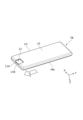
- Fig. 1 is a diagram showing an example use case of the electronic device TB.
- Fig. 2 is a diagram showing an example installation of the electronic device TB. It goes without saying that the use case shown in Fig. 1 is just one example and is not limited to this.
- the electronic device TB is, for example, a personal monitor that can be used to watch movies, play games, read, check flight status, etc., a seat monitor that can provide in-flight entertainment, or a tablet-type personal computer.
- the electronic device TB is fixedly installed in a seat of a vehicle such as an aircraft, or on a mounting stand ST within the seat, and is used by a user (e.g., a passenger, a passenger, etc.).
- the electronic device TB includes a monitor MN (an example of a first housing) and a cover CV (an example of a second housing), each made of a rigid material such as metal or carbon fiber.
- the electronic device TB is integrally formed by fitting the monitor MN and the cover CV together.
- the electronic device TB is used by a user after being placed on an installation stand ST with an adapter AD connected to it that can supply power to the electronic device TB.
- the adapter AD (see Figure 2) is connected to the rear of the electronic device TB from the direction opposite to the Y direction.
- the monitor MN and cover CV which are in a mated state, are screwed into the electronic device TB at a position corresponding to the connection point of the adapter AD using two screws 11A and 11B.
- the electronic device TB has two screws 11A, 11B inserted into two insertion holes 12A, 12B (see FIG. 5) provided in the cover CV, which are then screwed into screw holes (not shown) provided on the rear surface of the monitor MN.
- the adapter AD When the adapter AD is connected to the electronic device TB with the two screws 11A, 11B screwed into it, the screwed points of the two screws 11A, 11B are covered by the adapter AD. This allows the electronic device TB to protect the adapter AD and its connection points from vibrations caused by the aircraft.
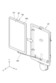
- FIG. 4 is a diagram showing an example of fitting the monitor MN and the cover CV.
- the electronic device TB shown in FIG. 4 shows a state in which the monitor MN and the cover CV are not fitted together.
- the electronic device TB engages the cover CV with the monitor MN by sliding the cover CV in a sliding direction U along the longitudinal direction of the electronic device TB with the peripheral portion 13B (see FIG. 5) of the cover CV abutting against the step portion 14A (one example of the peripheral portion of the first housing side of the monitor MN, see FIG. 6) of the monitor MN.
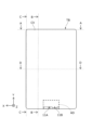
- FIG. 5 is a diagram showing the fitting structure of the cover CV.
- the cover CV shown in FIG. 5 is the surface that faces the rear surface of the monitor MN shown in FIG. 6 when fitted.
- the cover CV is formed in a substantially rectangular shape and has a back portion 15 and a second housing side peripheral portion 13 formed around the back portion 15 so as to be substantially perpendicular to the back portion 15.
- the second housing side peripheral portion 13 is formed substantially parallel to the display portion SC of the monitor MN and has a substantially rectangular peripheral portion 13B and an inner surface 13A formed continuously in a direction substantially perpendicular to the peripheral portion 13B.
- the inner surface 13A connects the peripheral portion 13B to the back portion 15 of the cover CV.
- the cover CV is provided with a pair of second housing side fittings 20 on the peripheral portion 13B of the second housing side peripheral portion 13 along the longitudinal direction.
- the cover CV also has an adapter receiving portion 12 on the side opposite the Y direction along the short side to which the adapter AD or a cord connected to the adapter AD is connected, and a second housing top fitting portion 30 on the inner surface 13A on the Y direction side (top side) opposite the side on which the adapter receiving portion 12 is provided.
- the adapter receiving portion 12 is formed to be recessed toward the front side of the monitor MN compared to the rear portion 16.
- the adapter receiving portion 12 has two insertion holes 12A, 12B.
- Each of the pair of second housing side fitting parts 20 is fitted with each of the pair of first housing side fitting parts 50 provided on the sides along the longitudinal direction of the monitor MN by the sliding operation described above.
- Each of the pair of second housing side fitting parts 20 is fitted with each of the pair of first housing side fitting parts 50, thereby restricting vibration and movement in the X and Z directions between the monitor MN and the cover CV.
- the second housing side fitting portion 20 includes a plurality of first side fitting portions 21 (an example of another fitting portion) and second side fitting portions 22 (an example of a fitting portion) formed approximately parallel to the display portion SC of the monitor MN on the second housing side peripheral portion 13. Note that the number and arrangement of the first side fitting portions 21 and second side fitting portions 22 shown in FIG. 5 are merely examples and are not limited to these.
- the second side fitting portion 22 is a surface along the sliding direction U, and a C surface 22A (an example of a sloped portion, see FIG. 9) is formed on the surface that abuts against the annular elastic body OL by the sliding operation. This makes it easier for the second side fitting portion 22 to slide over the step portion 14A of the first housing side peripheral portion 14 during the sliding operation and to slip between the step portion 14A and the annular elastic body OL provided on the first housing side fitting portion 50.
- the second housing top fitting portion 30 fits into the first housing top fitting portion 60 provided on the top surface of the monitor MN by the sliding operation described above. By fitting into the first housing top fitting portion 60, the second housing top fitting portion 30 restricts vibration and movement in the Y and Z directions between the monitor MN and the cover CV.
- the second housing top fitting portion 30 includes a first top fitting portion 31 (one example of a fitting portion), a second top fitting portion 32 (another fitting portion, one example of a concave-convex fitting portion), a vibration absorbing member 33, and an abutment portion 34.
- the first top fitting portion 31 is formed with a C surface 31A (one example of a slope portion, see FIG. 8) whose thickness in the Z direction gradually decreases along the sliding direction U. This makes it easier for the first top fitting portion 31 to slip between the step portion 14A and the annular elastic body OL when fitted.
- the number and arrangement of the first top fitting portion 31, the second top fitting portion 32, the vibration absorbing member 33, and the abutment portion 34 shown in FIG. 5 are merely examples and are not limited thereto.
- the vibration absorbing member 33 is made of a material capable of absorbing vibrations, such as a sponge. When slid, the vibration absorbing member 33 comes into contact with the uneven portion 62 formed on the side surface 14B on the upper surface side of the monitor MN, and absorbs vibrations in the Y direction between the cover CV and the monitor MN.
- the first side fitting portion 21, the second side fitting portion 22, the first top fitting portion 31, and the second top fitting portion 32 may be provided on the inner surface 13A side without being continuous with the peripheral portion 13B.
- FIG. 6 is a diagram showing an example of the mating structure of the monitor MN.
- the monitor MN shown in FIG. 6 is the surface that faces the inner surface of the cover CV shown in FIG. 5 when mated.
- the monitor MN is formed in a generally rectangular shape and has a rear portion 16 of the monitor MN and a first housing side peripheral portion 14 formed around the rear portion 16 so as to be generally perpendicular to the rear portion 16.
- the first housing side peripheral portion 14 is formed generally parallel to the display portion SC of the monitor MN and has a step portion 14A along which the peripheral portion 13B of the cover CV slides when slid, and a side surface 14B that connects the step portion 14A to the rear portion 16 in a direction generally perpendicular to the step portion 14A.
- the monitor MN has first housing side fitting portions 50 provided on the side surfaces 14B along the longitudinal direction of the first housing side peripheral portion 14.
- the monitor MN also has screw holes (not shown) into which two screws 11A, 11B can be screwed, provided on the side surfaces 14B along the short side direction of the first housing side peripheral portion 14 on the side opposite the Y direction, and has a first housing top fitting portion 60 on the Y direction side, i.e., on the side (top surface) of the side 14B opposite the side into which these two screws 11A, 11B are screwed.
- Each of the pair of first housing side engaging parts 50 engages with each of the pair of second housing side engaging parts 20 provided in the longitudinal direction of the cover CV by the sliding operation described above.
- Each of the pair of first housing side engaging parts 50 engages with each of the pair of second housing side engaging parts 20, thereby restricting vibration and movement of the monitor MN and cover CV in the X and Z directions.
- the first housing side fitting portion 50 includes a first side fitting portion 51 (one example of a fitting portion) and a second side fitting portion 52 (one example of another fitting portion). Note that the number and arrangement of the first side fitting portions 51 and the second side fitting portions 52 shown in FIG. 6 are merely examples and are not limited to these.
- the first side surface fitted portion 51 has a ring-shaped elastic body OL (an example of an elastic body) attached thereto.
- the ring-shaped elastic body OL is formed of, for example, rubber.
- at least one first side surface fitted portion 51 needs to be provided.
- the first side surface fitted portion 51 may be the same size as the second top surface fitted portion 63 provided on the first housing top surface fitted portion 60. This allows the electronic device TB to standardize the ring-shaped elastic body OL attached to each of the first side surface fitted portion 51 and the second top surface fitted portion 63, and to make maintenance easier.
- the second side engaging portion 52 is formed so that the thickness L14 in the Z direction is greater than the thickness L15 of the first side engaging portion 51. This allows the electronic device TB to effectively prevent the annular elastic body OL from being erroneously attached to the second side engaging portion 52 when the annular elastic body OL is attached or replaced.
- the first housing top surface mating portion 60 is mated with the second housing top surface mating portion 30 provided on the top surface of the cover CV by the sliding operation described above. By mating with the second housing top surface mating portion 30, the first housing top surface mating portion 60 restricts vibration and movement of the monitor MN and cover CV in the Y and Z directions.
- the first housing top surface fitted portion 60 includes a first top surface fitted portion 61, a concave-convex portion 62 (an example of another fitted portion), and a second top surface fitted portion 63 (an example of a fitted portion).
- the number and arrangement of the first top surface fitted portion 61, the concave-convex portion 62, and the second top surface fitted portion 63 shown in FIG. 6 are merely examples and are not limited to these.
- the first upper surface fitted portion 61 is formed on the side surface 14B of the upper surface located in the Y direction.
- the abutment portion 34 abuts against the first upper surface fitted portion 61 by a sliding operation.
- At least one uneven portion 62 is formed on the side surface 14B of the upper surface located in the Y direction.
- the ring-shaped elastic body OL is attached to the second upper surface fitted portion 63.
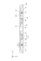
- Figure 7 is a cross-sectional view taken along line A-A, which illustrates an example of engagement between the monitor MN and cover CV on the top surface of the electronic device TB.
- Figure 8 is an enlarged view of the main parts of the cross-section taken along line B-B, which illustrates an example of engagement between the monitor MN and cover CV on the top surface of the electronic device TB.
- the second housing top engaging portion 30 engages with the first housing top engaged portion 60 of the monitor MN.
- the electronic device TB can absorb vibrations or rattles in the Y direction using the vibration absorbing member 33, and the first upper surface fitting portion 31, which is fitted between the step portion 14A and the annular elastic body OL and is held in the fitted state by the elastic force (restoring force) of the annular elastic body OL, can regulate vibrations or rattles in the Z direction.
- the monitor MN and cover CV are each formed from a rigid body, and individual differences based on the dimensional tolerances of the monitor MN and cover CV may result in gaps being formed at the mating points, i.e., between the opposing step portions 14A and peripheral portion 13B. Even in such cases, electronic device TB is able to close the gap between peripheral portion 13B of cover CV and step portion 14A of monitor MN and regulate vibration or rattling in the Z direction by urging peripheral portion 13B of cover CV toward step portion 14A of monitor MN via first side mating portion 21 due to the restoring force of ring-shaped elastic body OL.
- the three sides of the cover CV i.e., the second housing side engaging portion 20 and the second housing top engaging portion 30
- the top surface of the monitor MN i.e., the first housing side engaging portion 50 and the first housing top engaging portion 60
- the electronic device TB is fixed by screwing together the monitor MN and one side of the periphery of the cover CV in the opposite direction to the Y direction with screws 11A, 11B.
- the moment force of the electronic device TB centered on the screwed points of the screws 11A, 11B is greatest on the top surface. Therefore, even if the electronic device TB is subjected to shock or vibration, the vibration absorbing member 33 provided on the top surface can absorb the moment force acting on the mating portion between the monitor MN and cover CV on the top surface side.
- Figure 9 is an enlarged view of the essential parts of the CC cross section illustrating an example of engagement of the monitor MN and cover CV on the side of the electronic device TB.
- Figure 10 is an enlarged view of the essential parts of the D-D cross section illustrating the state of the first side engaged portion 51, the annular elastic body OL, and the first side engaging portion 21 when engaged.
- the pair of second housing side fitting portions 20 fit into the pair of first housing side fitting portions 50 of the monitors MN, respectively.
- the first side fitting portion 21 fits between the step portion 14A and the annular elastic body OL attached to the second upper surface fitting portion 63, and the second side fitting portion 22 fits between the step portion 14A and the second side fitting portion 52.
- the ring-shaped elastic body OL When the second side fitting portion 22 is inserted between the step portion 14A by the sliding operation, the ring-shaped elastic body OL is crushed in the opposite direction to the Z direction by the second side fitting portion 22.
- the ring-shaped elastic body OL biases the second side fitting portion 22 in the Z direction by its elastic force (restoring force).
- the peripheral portions 13B of the electronic device TB along the longitudinal direction of the cover CV are each biased in the Z direction, and come into contact with the step portion 14A along the longitudinal direction of the monitor MN.
- the first side fitting portion 21 of the electronic device TB is held in the fitted state by being inserted between the step portion 14A and the annular elastic body OL due to the restoring force of the annular elastic body OL.
- the monitor MN and cover CV are each formed from a rigid body, and gaps may form at the fitting points due to individual differences based on the dimensional tolerances of the monitor MN and cover CV. Even in such a case, electronic device TB is able to close the gap between peripheral portion 13B of cover CV and step portion 14A of monitor MN by urging peripheral portion 13B of cover CV toward step portion 14A of monitor MN via second side fitting portion 22 due to the restoring force of ring-shaped elastic body OL, and is able to regulate vibration or rattling in the Z direction.
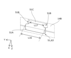
- FIG. 11 is a diagram illustrating an example of the first side surface fitted portion 51.
- the second upper surface fitted portion 63 has the same configuration and size as the first side surface fitted portion 51, so a description thereof will be omitted here.
- the first side fitting portion 51 is provided on the side 14B of the monitor MN.
- the first side fitting portion 51 has a retaining portion 51A and a connection portion 51C that connects the monitor MN and the retaining portion 51A, and is formed so that the retaining portion 51A and the connection portion 51C are substantially T-shaped when viewed from the Z direction.
- the connection portion 51C has a recess 51B formed in a direction along the side 14B of the monitor MN.
- the first side fitting portion 51 has a recess formed by two recesses 51B into which the annular elastic body OL is rotatably attached.
- the recesses 51B are formed such that the length L16 of the retaining portion 51A is longer than the length L17 of the connection portion (the length between the recesses 51B) in the direction along the side surface 14B of the monitor MN (sliding direction U). This allows the retaining portion 51A to function as a retainer for the annular elastic body OL attached to the recesses 51B.
- the first side fitting portion 51 may be formed in a generally L-shape when viewed from the Z direction.
- the connection portion 51C has a recess 51B formed only on one side of the connection portion 51C in the direction along the side surface 14B of the monitor MN.
- FIG. 12 is an enlarged view of the main part of the B-B cross section illustrating an example of fitting between the monitor MNX and the cover CVX in a modified example of the embodiment. Note that, in Fig. 12, for simplicity of explanation, only the fitting between the first side fitted portion 51X and the second side fitted portion 22X is illustrated, and only the fitting between the first side fitted portion 51X and the second side fitted portion 22X will be described.
- the cover CVX in the modified embodiment has, on the inner surface 13AX, a first side surface engaging portion 51X and a second top surface engaging portion 63X that respectively correspond to the first side surface engaging portion 51 and the second top surface engaging portion 63 of the monitor MN.
- the monitor MNX in the modified embodiment also has, on the side surface 14B, a second side surface engaging portion 22X and a first top surface engaging portion 31X that respectively correspond to the second side surface engaging portion 22 and the first top surface engaging portion 31 of the cover CV.
- the inner surface 13AX corresponds to the inner surface 13A in the embodiment
- the peripheral portion 13BX corresponds to the peripheral portion 13B in the embodiment
- the step portion 14AX corresponds to the step portion 14A in the embodiment
- the side surface 14BX corresponds to the side surface 14B in the embodiment.
- the first side fitting portion 51X has a retaining portion 51AX and a recess 52BX, similar to the first side fitting portion 51 in the embodiment.
- a ring-shaped elastic body OL is rotatably attached to the recess 52X. Note that the ring-shaped elastic body OL in the modified embodiment is similar to the ring-shaped elastic body OL in the embodiment, and therefore a description thereof will be omitted.
- the second side fitting portion 22X is inserted between the step portion 14AX and the annular elastic body OL by sliding operation and fits into place.
- the electronic device TB includes a monitor MN (an example of a first housing), a cover CV (an example of a second housing) having a second side fitting portion 22 and a first top fitting portion 31 (an example of a fitting portion), and an annular elastic body OL (an example of an annular body).
- the monitor MN has at least one first side fitting portion 51 and a second top fitting portion 63 (an example of a fitting portion) that are fitted with the second side fitting portion 22 and the first top fitting portion 31 by being slid in a first direction (specifically, the direction opposite to the Y direction, the direction in which the adapter AD is connected), and a step portion 14A (an example of a first housing side peripheral portion) provided on the periphery of the monitor MN.
- the annular elastic body OL is located between the first side fitting portion 51 and the second top fitting portion 63 and the step portion 14A.
- the monitor MN and cover CV can be assembled together without using parts such as screws, thereby suppressing an increase in the number of parts mounted on the electronic device TB. Furthermore, since the monitor MN and cover CV of the electronic device TB are biased in a direction toward each other by the elastic ring-shaped elastic body OL, even if the monitor MN or cover CV vibrates due to an external force, the vibrations can be absorbed by the ring-shaped elastic body OL, and rattle between the monitor MN and cover CV after assembly can be more effectively suppressed.
- either the monitor MN or the cover CV of the electronic device TB according to the embodiment further includes a display surface (display unit SC) that displays information to the user.
- the step portion 14A is formed by a surface that is approximately parallel to the display surface. This allows the electronic device TB according to the embodiment to assist in visually checking whether the monitor MN and the cover CV are fitted together after assembly.
- the annular elastic body OL of the electronic device TB according to the embodiment is provided on a fitting surface where the first side fitting portion 51 and the second top surface fitting portion 63, and the second side fitting portion 22 and the first top surface fitting portion 31 are fitted together by sliding.
- the first side fitting portion 51 and the second top surface fitting portion 63 are fitted together by sliding with the second side fitting portion 22 and the first top surface fitting portion 31 via the annular elastic body OL.
- the annular elastic body OL of the electronic device TB according to the embodiment has an annular shape and is provided surrounding the periphery of the first side surface fitted portion 51 and the second top surface fitted portion 63.
- the electronic device TB according to the embodiment can omit the parts for attaching the annular elastic body OL to the first side surface fitted portion 51 and the second top surface fitted portion 63, and an increase in the number of parts mounted on the electronic device TB can be suppressed.
- the first side surface fitted portion 51 and the second top surface fitted portion 63 of the electronic device TB according to the embodiment have a retaining portion 51A and a connecting portion 51C that connects the monitor MN on which the first side surface fitted portion 51 and the second top surface fitted portion 63 are provided to the retaining portion 51A.
- the length of the retaining portion 51A in the sliding direction is longer than the length of the connecting portion 51C.
- the ring-shaped elastic body OL is provided so as to surround the connecting portion 51C.
- the first side surface fitted portion 51 and the second top surface fitted portion 63 of the electronic device TB according to the embodiment are connected so that the retaining portion 51A and the connection portion 51C form a substantial T-shape.
- the electronic device TB according to the embodiment can prevent the annular elastic body OL from falling out without using parts for preventing the annular elastic body OL from falling out of the first side surface fitted portion 51 and the second top surface fitted portion 63.
- the electronic device TB according to the embodiment further includes at least one first side engaging portion 21 and second top engaging portion 32 (an example of another engaging portion) provided on the cover CV of the electronic device TB, and at least one second side engaged portion 52 and uneven portion 62 (an example of another engaged portion) provided on the monitor MN and engaged with the first side engaging portion 21 and the second top engaging portion 32 by sliding along the first direction.
- the outer shapes of the second side engaged portion 52 and uneven portion 62 are larger than the outer shapes of the first side engaged portion 51 and the second top engaged portion 63.
- the second side fitting portion 22 and the first top fitting portion 31 of the electronic device TB according to the embodiment are provided on the second housing side peripheral portion 13, which is the periphery of the cover CV, and the first housing side peripheral portion 14 and the second housing side peripheral portion 13 abut against each other based on the fitting of the second side fitting portion 22 and the first top fitting portion 31 with the first side fitted portion 51 and the second top fitted portion 63.
- the electronic device TB according to the embodiment can assemble the monitor MN and the cover CV so that there are no gaps in the external appearance where the monitor MN and the cover CV come into contact.
- the monitor MN or cover CV of the electronic device TB includes an adapter receiving portion 12, which is the connection point between the electronic device TB and an adapter AD connected to the electronic device TB.
- the monitor MN and cover CV are fixed at the adapter receiving portion 12. This allows the electronic device TB according to the embodiment to protect the electrical or physical connection of the adapter receiving portion 12, which is the connection point on the periphery of the monitor MN and cover CV to which the adapter AD, etc. are connected.
- the monitor MN and cover CV of the electronic device TB according to the embodiment are formed in a generally rectangular shape.
- the adapter receiving portion 12 is provided on the side in the first direction of either the monitor MN or the cover CV.
- the second side fitting portion 22, the first top fitting portion 31, the first side fitted portion 51 and the second top fitting portion 63 are provided on each side other than the first direction.
- annular elastic bodies OL of the electronic device TB according to the embodiment are the same size. This allows the electronic device TB according to the embodiment to standardize the annular elastic bodies OL attached to the first side surface fitted portion 51 and the second top surface fitted portion 63, and makes maintenance easier.
- the monitor MN of the electronic device TB according to the embodiment further includes an uneven portion 62 having an uneven shape on the side opposite the first direction.
- the cover CV further includes a vibration absorbing member 33 on the side opposite the first direction.
- the vibration absorbing member 33 abuts against the uneven portion 62 by sliding along the first direction.
- the electronic device TB according to the embodiment can absorb vibrations of the electronic device TB in the direction opposite the first direction in the open state, and therefore can more effectively suppress rattling between the monitor MN and the cover CV after assembly.
- the vibration absorbing member 33 can absorb (absorb) the moment force generated around the screwed position based on an external force applied to the electronic device TB.
- the cover CV of the electronic device TB according to the embodiment further includes a second top surface fitting portion 32 (an example of a concave-convex fitting portion) that fits with the concave-convex portion 62 on the side opposite the first direction.
- a second top surface fitting portion 32 an example of a concave-convex fitting portion
- the length L12 of the concave-convex portion 62 is greater than the length L13 of the second top surface fitting portion 32.
- the second side fitting portion 22 and the first top fitting portion 31 of the electronic device TB according to the embodiment have C surfaces 22A, 31A (an example of a sloped portion) that protrude from the peripheral portion of the cover CV and have a protruding height that decreases along the first direction. This makes it easier for the second side fitting portion 22 and the first top fitting portion 31 to fit into the first side fitted portion 51 and the second top fitted portion 63 by sliding in the electronic device TB according to the embodiment.
- the monitor MN and cover CV of the electronic device TB according to the embodiment have rigidity.
- the electronic device TB according to the embodiment can more effectively suppress rattling between the monitor MN and cover CV after assembly by using the elastic ring-shaped elastic body OL, even if there are individual differences in the dimensions of the monitor MN and cover CV based on dimensional tolerances.
- This disclosure is useful as a proposal for an electronic device that more effectively suppresses rattling of the electronic device after assembly.
Landscapes
- Engineering & Computer Science (AREA)
- General Engineering & Computer Science (AREA)
- Theoretical Computer Science (AREA)
- Mechanical Engineering (AREA)
- Aviation & Aerospace Engineering (AREA)
- Physics & Mathematics (AREA)
- Microelectronics & Electronic Packaging (AREA)
- General Physics & Mathematics (AREA)
- Chemical & Material Sciences (AREA)
- Combustion & Propulsion (AREA)
- Acoustics & Sound (AREA)
- Human Computer Interaction (AREA)
- Computer Hardware Design (AREA)
- Casings For Electric Apparatus (AREA)
Abstract
Priority Applications (3)
| Application Number | Priority Date | Filing Date | Title |
|---|---|---|---|
| PCT/JP2023/020899 WO2024252502A1 (fr) | 2023-06-05 | 2023-06-05 | Dispositif électronique |
| EP23940609.3A EP4722847A1 (fr) | 2023-06-05 | 2023-06-05 | Dispositif électronique |
| US19/408,956 US20260089853A1 (en) | 2023-06-05 | 2025-12-04 | Electronic device |
Applications Claiming Priority (1)
| Application Number | Priority Date | Filing Date | Title |
|---|---|---|---|
| PCT/JP2023/020899 WO2024252502A1 (fr) | 2023-06-05 | 2023-06-05 | Dispositif électronique |
Related Child Applications (1)
| Application Number | Title | Priority Date | Filing Date |
|---|---|---|---|
| US19/408,956 Continuation US20260089853A1 (en) | 2023-06-05 | 2025-12-04 | Electronic device |
Publications (1)
| Publication Number | Publication Date |
|---|---|
| WO2024252502A1 true WO2024252502A1 (fr) | 2024-12-12 |
Family
ID=93795442
Family Applications (1)
| Application Number | Title | Priority Date | Filing Date |
|---|---|---|---|
| PCT/JP2023/020899 Ceased WO2024252502A1 (fr) | 2023-06-05 | 2023-06-05 | Dispositif électronique |
Country Status (3)
| Country | Link |
|---|---|
| US (1) | US20260089853A1 (fr) |
| EP (1) | EP4722847A1 (fr) |
| WO (1) | WO2024252502A1 (fr) |
Citations (5)
| Publication number | Priority date | Publication date | Assignee | Title |
|---|---|---|---|---|
| JPH01173981U (fr) * | 1988-05-26 | 1989-12-11 | ||
| JP2002247715A (ja) * | 2001-02-20 | 2002-08-30 | Kawamura Electric Inc | 分電盤 |
| JP2007335201A (ja) * | 2006-06-14 | 2007-12-27 | Sharp Corp | 電子機器カバーのロック構造 |
| JP2019010534A (ja) * | 2015-06-12 | 2019-01-24 | 任天堂株式会社 | 支持装置 |
| JP2020135752A (ja) | 2019-02-25 | 2020-08-31 | 富士通クライアントコンピューティング株式会社 | 電子機器の筐体 |
-
2023
- 2023-06-05 WO PCT/JP2023/020899 patent/WO2024252502A1/fr not_active Ceased
- 2023-06-05 EP EP23940609.3A patent/EP4722847A1/fr active Pending
-
2025
- 2025-12-04 US US19/408,956 patent/US20260089853A1/en active Pending
Patent Citations (5)
| Publication number | Priority date | Publication date | Assignee | Title |
|---|---|---|---|---|
| JPH01173981U (fr) * | 1988-05-26 | 1989-12-11 | ||
| JP2002247715A (ja) * | 2001-02-20 | 2002-08-30 | Kawamura Electric Inc | 分電盤 |
| JP2007335201A (ja) * | 2006-06-14 | 2007-12-27 | Sharp Corp | 電子機器カバーのロック構造 |
| JP2019010534A (ja) * | 2015-06-12 | 2019-01-24 | 任天堂株式会社 | 支持装置 |
| JP2020135752A (ja) | 2019-02-25 | 2020-08-31 | 富士通クライアントコンピューティング株式会社 | 電子機器の筐体 |
Also Published As
| Publication number | Publication date |
|---|---|
| US20260089853A1 (en) | 2026-03-26 |
| EP4722847A1 (fr) | 2026-04-08 |
Similar Documents
| Publication | Publication Date | Title |
|---|---|---|
| US8576577B2 (en) | Avionic equipment item | |
| KR101057838B1 (ko) | 인터페이싱 부분들을 결합하기 위한 시스템 | |
| US7137767B2 (en) | Storage media drive isolation apparatus and methods | |
| WO2007060952A1 (fr) | Support de fixation de connecteur, raccord de fixation de connecteur, structure de fixation de connecteur, connecteur renforce cote equipement et equipement d’automatisation industrielle | |
| US5161770A (en) | Shock absorbent mounting arrangement for disk drive or other component | |
| TW201836458A (zh) | 用於電子裝置之電路板之避震結構及其電子裝置 | |
| CN111692464A (zh) | 用于监视器附接的系统和方法 | |
| US6310769B1 (en) | Mounting bracket assembly for system components in a computer | |
| US20260089853A1 (en) | Electronic device | |
| TWI481330B (zh) | 顯示裝置 | |
| JPWO2013136367A1 (ja) | 電子機器 | |
| CN102638014A (zh) | 连接结构 | |
| US12435542B2 (en) | Electric lock and housing thereof | |
| CN104111546B (zh) | 显示装置 | |
| CN207895797U (zh) | 一种汽车仪表液晶屏幕的安装结构 | |
| CN219392880U (zh) | 一种具有防护机构的显示屏 | |
| CN116193013B (zh) | 电子设备 | |
| CN218887706U (zh) | 一种hdmi接口的连接结构及显示设备 | |
| JPWO2005080137A1 (ja) | アウターミラー | |
| EP4027465A1 (fr) | Couvercle de connecteur pour automobile | |
| TWI896341B (zh) | 伺服器裝置及限位件 | |
| JPWO2020095635A1 (ja) | 電子制御装置 | |
| TW202147961A (zh) | 承載組件 | |
| TW202147960A (zh) | 承載組件 | |
| CN222690108U (zh) | 硬盘支架及电子设备 |
Legal Events
| Date | Code | Title | Description |
|---|---|---|---|
| 121 | Ep: the epo has been informed by wipo that ep was designated in this application |
Ref document number: 23940609 Country of ref document: EP Kind code of ref document: A1 |
|
| ENP | Entry into the national phase |
Ref document number: 2023940609 Country of ref document: EP Effective date: 20260105 |
|
| WWE | Wipo information: entry into national phase |
Ref document number: 2023940609 Country of ref document: EP |
|
| NENP | Non-entry into the national phase |
Ref country code: DE |
|
| ENP | Entry into the national phase |
Ref document number: 2023940609 Country of ref document: EP Effective date: 20260105 |
|
| ENP | Entry into the national phase |
Ref document number: 2023940609 Country of ref document: EP Effective date: 20260105 |
|
| ENP | Entry into the national phase |
Ref document number: 2023940609 Country of ref document: EP Effective date: 20260105 |
|
| ENP | Entry into the national phase |
Ref document number: 2023940609 Country of ref document: EP Effective date: 20260105 |
|
| ENP | Entry into the national phase |
Ref document number: 2023940609 Country of ref document: EP Effective date: 20260105 |
|
| WWP | Wipo information: published in national office |
Ref document number: 2023940609 Country of ref document: EP |