WO2024252515A1 - モータ装置 - Google Patents
モータ装置 Download PDFInfo
- Publication number
- WO2024252515A1 WO2024252515A1 PCT/JP2023/020978 JP2023020978W WO2024252515A1 WO 2024252515 A1 WO2024252515 A1 WO 2024252515A1 JP 2023020978 W JP2023020978 W JP 2023020978W WO 2024252515 A1 WO2024252515 A1 WO 2024252515A1
- Authority
- WO
- WIPO (PCT)
- Prior art keywords
- motor
- mounting portion
- end wall
- stator
- mounting
- Prior art date
- Legal status (The legal status is an assumption and is not a legal conclusion. Google has not performed a legal analysis and makes no representation as to the accuracy of the status listed.)
- Ceased
Links
Images


Classifications
-
- H—ELECTRICITY
- H02—GENERATION; CONVERSION OR DISTRIBUTION OF ELECTRIC POWER
- H02K—DYNAMO-ELECTRIC MACHINES
- H02K5/00—Casings; Enclosures; Supports
- H02K5/24—Casings; Enclosures; Supports specially adapted for suppression or reduction of noise or vibrations
Definitions
- This disclosure relates to a motor device.
- a motor device has, for example, a case, a stator, and a rotor.
- the case, stator, and rotor are each cylindrical bodies having a circular cross-sectional shape.
- the stator is fixed to the inner peripheral surface of the case.
- the rotor is inserted axially into the stator.
- the rotor is rotatable relative to the inner peripheral surface of the stator.
- the motor in Patent Document 1 employs the following configuration. That is, the motor is fixed to the mounting object via a plate.
- the plate has a base portion and two mounting portions.
- the plate is a circular plate member, and is fixed to the axial end of the motor case body.
- the two mounting portions extend radially outward from the outer periphery of the base portion in opposite directions.
- the mounting portions are fixed to the mounting object.
- the mounting portion protrudes radially outward beyond the outer circumferential surface of the case body.
- the portion of the axial end of the case body that has the plate is less susceptible to radial deformation than the case body. This makes it possible to prevent vibrations caused by the expansion and contraction deformation of the stator from being transmitted to the mounting object.
- the motor device of Patent Document 1 certainly makes it possible to suppress the transmission of vibrations to the object to which the motor is attached.
- a separate plate must be prepared.
- a motor device is a motor device having a motor.
- the motor has a first end and a second end located opposite each other in the axial direction, and the second end is configured to be attached to an attachment target.
- the second end has an end wall that closes the second end, and an attachment portion configured to attach the motor to the attachment target, the attachment portion being provided on the outer circumferential surface of the second end.
- the end wall is disposed at a position in the axial direction of the motor that corresponds to the attachment portion.
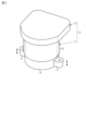
- FIG. 1 is a perspective view of a motor device according to an embodiment of the present invention.
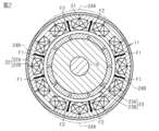
- FIG. 2 is a cross-sectional view of the motor of FIG. 1 taken in a direction perpendicular to the axial direction.
- FIG. 3 is a perspective view showing the motor of FIG. 1 in enlarged and contracted states.
- FIG. 4 is a cross-sectional view showing a main part of the motor shown in FIG.
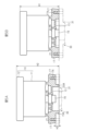
- FIG. 5A is a partial cross-sectional view of a motor device according to a comparative example that does not have the first configuration
- FIG. 5B is a partial cross-sectional view of a motor device according to one embodiment that has the first configuration.
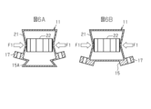
- FIG. 6A is a schematic diagram of a motor case according to a comparative example not having the first configuration
- FIG. 6B is a schematic diagram of a motor case according to one embodiment having the first configuration.
- FIG. 7 is a graph showing the degree of deformation of a tightening portion according to a comparative example not having the first configuration and the degree of deformation of a tightening portion according to one embodiment having the first configuration.
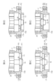
- FIG. 8A is a cross-sectional view showing the main parts of a motor according to a comparative example in which the end wall is located at a first axial position
- FIG. 8B is a cross-sectional view showing the main parts of a motor according to a comparative example in which the end wall is located at a second axial position
- FIG. 8C is a cross-sectional view showing the main parts of a motor according to a comparative example in which the end wall is located at a third axial position
- FIG. 8D is a cross-sectional view showing the main parts of a motor according to a comparative example in which the end wall is located at a fourth axial position
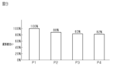
- FIG. 9 is a graph showing the degree of deformation of the fastening portion according to the comparative example in which the end wall is located at the first to fourth axial positions.
- FIG. 10 is a cross-sectional view showing a main part of a motor according to a comparative example that does not have the third configuration.
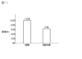
- FIG. 11 is a graph showing the degree of deformation of a tightening portion according to a comparative example not having the third configuration and the degree of deformation of a tightening portion according to one embodiment having the third configuration.
- FIG. 12 is a graph showing the degree of deformation of a tightening portion in a comparative example that does not have the first to third configurations and the degree of deformation of a tightening portion in one embodiment that has the first to third configurations.
- the motor device 10 has a motor 11 and an electronic control device 12.
- the motor 11 is, for example, a three-phase brushless motor.
- the three phases are a U-phase, a V-phase, and a W-phase.
- the electronic control device 12 is provided at a first end of the motor 11.
- the electronic control device 12 controls the driving of the motor 12.
- the electronic control device 12 has a case and a board housed in the case.
- the board has electronic components for controlling the driving of the motor 11.
- the second end of the motor 11 has an end wall 13, a peripheral wall 14, and a fitting recess 15.
- the second end is the end opposite the first end in the axial direction of the motor 11.
- the end wall 13 is a circular wall that extends in a direction perpendicular to the axial direction of the motor 11, and closes the second end of the motor 11.
- the peripheral wall 14 is a cylindrical body with a circular cross-sectional shape, and is provided along the peripheral edge of the end wall.
- the first axial end face of the peripheral wall 14 is connected to the end wall 13.
- the fitting recess 15 is a concave portion into which a part of the mounting target of the motor device 10 is fitted, and is a portion surrounded by the peripheral wall 14.
- the fitting recess 15 opens in the direction from the first end to the second end of the motor 11.
- the motor 11 has an output shaft 16.
- the axis of the output shaft 16 coincides with the axis of the motor 11.
- a first end of the output shaft 16 is located inside the motor 11.
- a second end of the output shaft 16 passes through the end wall 13 without contacting the end wall 13 and is exposed inside the mating recess 15.
- the protruding height of the output shaft 16 from the end wall 13 is, for example, the same as the depth of the mating recess 15. The depth is the axial length of the mating recess 15.
- the motor 11 has two mounting portions 17.
- the mounting portions 17 are used to mount the motor 11 to an object.
- the mounting portions 17 are provided on the outer peripheral surface of the peripheral wall 14.
- the two mounting portions 17 extend radially opposite each other in the direction of the motor 11.
- the mounting portions 17 have two end faces located opposite each other in the axial direction.
- the first end face is the surface of the mounting portion 17 opposite the opening direction of the fitting recess 15.
- the second end face is the surface of the mounting portion 17 on the same side as the opening direction of the fitting recess 15, and is flush with the second end face of the peripheral wall 14.
- the mounting portion 17 has a screw hole 17A.
- the screw hole 17A is a non-through hole that opens into the second end face of the mounting portion 17.
- the inner peripheral surface of the screw hole 17A has a female thread.
- the motor device 10 is attached to an object via the attachment portion 17.
- the object is, for example, a reducer.
- One example of the reducer is a worm reducer.
- the worm reducer has a worm wheel, a worm, and a reducer housing.
- the worm wheel and the worm are accommodated inside the reducer housing.
- a part of the reducer housing is fitted into the fitting recess 15.
- the worm wheel is attached to a shaft, for example, so as to be integrally rotatable therewith.
- the worm is coaxially connected to the output shaft 16.
- the worm wheel and the worm mesh with each other.
- the rotation of the motor 11 is transmitted to the shaft via the reducer.
- the shaft may be a steering shaft of a vehicle, or a pinion shaft that meshes with rack teeth of a steered shaft.
- the motor 11 has a motor case 21, a stator 22, and a rotor 23.
- the motor case 21, the rotor 23, and the stator 22 are each a cylindrical body having a circular cross-sectional shape.
- the outer peripheral surface of the stator 22 is fixed to the inner peripheral surface of the motor case 21.
- the stator 22 has a core 22A and multiple coils 22B.
- the core 22A is made up of multiple split cores arranged closely together along the inner peripheral surface of the motor case 21.
- the split cores have teeth.
- the teeth are provided on the inner peripheral surface of the split cores.
- the coils 22B are wound around the teeth via insulators.
- the rotor 23 is disposed inside the stator 22.
- the rotor 23 has a rotor core 23A and multiple rotor magnets 23B.
- the rotor core 23A can rotate integrally with the output shaft 16.
- the output shaft 16 passes through the rotor core 23A in the axial direction.
- the rotor magnets 23B are permanent magnets, and are fixed to the outer peripheral surface of the rotor core 23A with a circumferential gap between them.
- the rotor magnets 23B are magnetized in the radial direction of the rotor core 23A.
- the magnetization directions of two rotor magnets 23B adjacent to each other in the circumferential direction are opposite to each other.
- the coil 22B When current is applied, the coil 22B generates a magnetic field, which generates a magnetic attraction force F1 and a magnetic repulsion force F2 between the stator 22 and the rotor 23.
- the rotor 23 rotates due to the magnetic attraction force F1 and the magnetic repulsion force F2.
- Motor 11 is a so-called "10-pole, 12-slot” motor. That is, motor 11 has 10 poles and 12 slots.
- the number of poles is the number of magnetic poles of rotor 23.
- the number of slots is the number of spaces between two circumferentially adjacent teeth, and is the number of spaces in which coil 22B can be accommodated.
- ⁇ Regarding expansion/contraction vibration of motor 11> As shown in Fig. 2, when the motor 11 is driven, a magnetic attraction force F1 and a magnetic repulsion force F2 are generated between the stator 22 and the rotor 23, causing the stator 22 to expand and contract in the radial direction.
- the expansion and contraction refers to the expansion and contraction of the outer diameter of the stator 22.
- the manner in which the stator 22 is deformed is determined by the relationship between the number of poles and the number of slots of the motor 11.
- the outer periphery of the stator 22 is deformed so that two or more enlarged diameter portions and two or more reduced diameter portions are alternately generated at equal angular intervals, and the number of each of the enlarged diameter portions and reduced diameter portions is equal to the greatest common divisor of the number of poles and the number of slots of the motor 11.
- the enlarged diameter portions are the parts of the stator 22 that are enlarged in diameter.
- the reduced diameter portions are the parts of the stator 22 that are reduced in diameter.
- the motor 11 is a "10 pole, 12 slot” motor
- the greatest common denominator between the number of poles and the number of slots of the motor 11 is "2". Therefore, as shown by the two-dot chain line in FIG. 2, when viewed from the axial direction of the stator 22, the enlarged diameter portions 24A and the reduced diameter portions 24B are alternately generated at 90° intervals in the circumferential direction of the stator 22.
- the outer periphery of the stator 22 elastically deforms into an ellipse.
- the outer periphery of the stator 22 elastically deforms such that the ellipse rotates with the rotation of the rotor 23.
- the position of the major axis of the ellipse moves sequentially in the circumferential direction.
- the cylindrical portion of the motor case 21 deforms so as to bulge radially outward.
- the cylindrical portion of the motor case 21 deforms so as to shrink radially inward.
- the expansion and contraction deformation of the cylindrical portion of the motor case 21 induces deformation in which the mounting portion 17 of the motor 11 is displaced in the axial direction, i.e., the up and down direction in Figure 3.
- the two mounting portions 17 swing in the same direction.
- the expansion and contraction deformation of the stator 22 raises the following concerns.
- the expansion and contraction deformation of the stator 22 is one of the causes of vibration of the stator 22.
- the vibration of the stator 22 is transmitted to the object to which the motor device 10 is attached via the motor case 21.
- the vibration is more likely to be transmitted to the object to which the mounting portion 17 is attached as a result of the mounting portion 17 swinging in the axial direction.
- the object to be attached is a reduction gear and the shaft is the steering shaft of a vehicle, there is a risk that vibrations will be transmitted to the steering shaft via the reduction gear. This could cause the steering shaft, and ultimately the steering wheel connected to the steering shaft, to vibrate. There is also concern that noise may be generated due to vibrations of the stator 22.
- the mounting object 30 has a housing 31.
- the housing 31 has a mounting surface 32.
- the mounting surface 32 is the surface of the housing 31 to which the motor device 10 is fixed.
- the mounting surface 32 has a mating protrusion 33.
- the mating protrusion 33 is a cylindrical body having a circular cross-sectional shape.
- the outer diameter of the mating protrusion 33 is approximately the same as the inner diameter of the mating recess 15.
- the outer peripheral surface of the mating protrusion 33 is mated with the inner peripheral surface of the mating recess 15.
- the first configuration is to have a mating recess 15 into which the mating protrusion 33 fits.
- the housing 31 has two fastening portions 34.
- the fastening portion 34 is a flat portion of the housing 31 that corresponds to the mounting portion 17 in the axial direction.
- the fastening portion 34 has two end faces that are opposite each other in the axial direction.
- the first end face is the face of the fastening portion 34 that faces the protruding direction of the fitting protrusion 33.
- the second end face is the face of the fastening portion 34 that faces the opposite direction to the protruding direction of the fitting protrusion 33.
- the fastening portion 34 has an insertion hole 34A.
- the insertion hole 34A passes through the fastening portion 34 in the axial direction.
- the screw hole 17A of the motor 11 coincides with the insertion hole 34A of the housing 31.
- the motor device 10 is fixed to the housing 31 by a bolt 35.
- the bolt 35 is fastened to the screw hole 17A through the insertion hole 34A.
- the end wall 13 of the motor 11 is a part of the motor case 22 and is provided so as to close a second end of the motor case 22.
- the end wall 13 has two end faces located opposite each other in the axial direction.
- the first end face is the end face of the end wall 13 opposite the fitting recess 15 in the axial direction.
- the second end face is the end face of the end wall 13 exposed inside the fitting recess 15 in the axial direction.
- the axial thickness of the end wall 13 is thinner than the axial thickness of the mounting portion 17.
- the end wall 13 is disposed between the center position P0 of the mounting portion 17 and the first end face of the mounting portion 17 in the axial direction.
- the first end face of the mounting portion 17 is the end face opposite the mounting target 30 in the axial direction.
- the axial position of the end wall 13 coincides with the center position P0 of the mounting portion 17.
- the axial position of the end wall 13 is based on the second end face of the end wall 13.
- the first end face of the end wall 13 is disposed in a position closer to the first end face of the mounting portion 17 than the center position P of the mounting portion 17 in the axial direction.
- the first end face of the end wall 13 is disposed between the center position P of the mounting portion 17 and the first end face of the mounting portion 17 in the axial direction.
- the second end face of the end wall 13 is disposed in the same position as the center position P0 of the mounting portion 17 in the axial direction.
- the second configuration is that the axial position of the end wall 13 coincides with the center position P0 of the mounting portion 17.
- the end wall 13 has a bearing retaining portion 25.
- the bearing retaining portion 25 is provided on a first end face of the end wall 13.
- the first end face is the end face of the end wall 13 opposite the mounting object 30.
- the bearing retaining portion 25 is a cylindrical body with a circular cross-sectional shape.
- the outer peripheral surface of the bearing 26 is fitted into the inner peripheral surface of the bearing retaining portion 25.
- the second end of the output shaft 16 is rotatably supported with respect to the motor case 21 via the bearing 25.
- the second end of the output shaft 16 passes through the end wall 13 in the axial direction in a non-contact state.
- the stator 22 has two end faces located opposite to each other in the axial direction.
- the first end face is the end face of the stator 22 farther from the end wall 13 in the axial direction.
- the second end face is the end face of the stator 22 closer to the end wall 13 in the axial direction.
- the stator 22 is spaced apart from the mounting portion 17 in the axial direction.
- the second end face of the stator 22 is spaced apart from the first end face of the mounting portion 17 by a distance ⁇ in the axial direction. That is, the stator 22 is disposed so as not to face the mounting portion 17 in the radial direction.
- the third configuration is that the stator 22 is spaced apart from the mounting portion 17 in the axial direction, and therefore does not have a portion that faces the mounting portion 17 in the radial direction.
- the distance ⁇ is set to a length within an allowable range determined according to product specifications and the like.
- the outer peripheral surface of the fitting protrusion 33 fits into the inner peripheral surface of the fitting recess 15. This makes it possible to reduce the axial length of the motor device 10.
- the mating protrusion 15A is a cylindrical body having a circular cross-sectional shape.
- the housing 31 of the mounting object 30 has a mating recess 33A instead of the mating protrusion 33.
- the mating recess 33A is a concave portion into which the mating protrusion 15A is fitted.
- the outer diameter of the mating protrusion 15A is approximately the same as the inner diameter of the mating recess 33A.
- the outer peripheral surface of the mating protrusion 15A is fitted into the inner peripheral surface of the mating recess 33A.
- the axial length H1 of the motor device 10 of the present embodiment shown in FIG. 5B is shorter than the axial length H2 of the motor device 10 of the comparative example shown in FIG. 5A by the axial length H3 of the fitting protrusion 15A of the comparative example.
- Length H3 is the length based on the second end face of the mounting portion 17.
- the amount of radial deformation of the inner circumferential surface of the mating recess 15 associated with the expansion and contraction of the cylindrical portion of the motor case 21 is less than the amount of radial deformation of the outer circumferential surface of the mating protrusion 15A of the comparative example associated with the expansion and contraction of the cylindrical portion of the motor case 21. Therefore, the effect of deformation of the inner circumferential surface of the mating recess 15 relative to the outer circumferential surface of the mating protrusion 33 of this embodiment is less than the effect of deformation of the outer circumferential surface of the mating protrusion 15A relative to the inner circumferential surface of the mating recess 33A of the comparative example.
- the degree of deformation of the mounting portion 17 in the comparative example shown in FIG. 5A is "100%
- the degree of deformation of the mounting portion 17 in the present embodiment shown in FIG. 5B is, for example, "94%”.
- the deformation of the mounting portion 17 is suppressed. Therefore, the transmission of vibrations accompanying the expansion and contraction deformation of the stator 22 to the mounting object 30 is suppressed.
- the end wall 13 is disposed axially between the center position P0 of the mounting portion 17 and the first end face of the mounting portion 17. This improves the overall rigidity of the mounting portion 17. Also, it becomes possible for the entire mounting portion 17 to bear the expansion and contraction deformation of the cylindrical portion of the motor case 21 evenly. This suppresses axial swing of the mounting portion 17. As a result, the vibrations caused by the expansion and contraction deformation of the stator 22 are suppressed from being transmitted to the mounting target 30.
- the second configuration that suppresses vibration transmission can be incorporated into the motor device 10 without increasing the axial length of the motor device 10.
- the first axial position P1 is a position where the end wall 13 is axially separated from the second end face of the mounting portion 17, i.e., a position where the end wall 13 does not face the mounting portion 17 in the radial direction.
- the second end face is the face of the mounting portion 17 that is farther from the stator 22 in the axial direction.
- the second axial position P2 is a position where the second end surface of the end wall 13 is disposed flush with the second end surface of the mounting portion 17 .
- the third axial position P3 is a position where the second end face of the end wall 13 coincides with the center position P0 of the mounting portion 17 in the axial direction.
- the fourth axial position P4 is a position where the second end face of the end wall 13 is located closer to the first end face of the mounting portion 17 than the center position P0 of the mounting portion 17. As shown in FIG. 9, the closer the axial position of the end wall 13 is to the first end face of the mounting portion 17, the smaller the degree of deformation of the mounting portion 17 becomes.
- the degree of deformation of the mounting portion 17 when the end wall 13 is positioned at the first axial position P1 is "100%”
- the degree of deformation of the mounting portion 17 when the end wall 13 is positioned at the second axial position P2 is "88%”.
- the degree of deformation of the mounting portion 17 when the end wall 13 is positioned at the third axial position P3 is "83%”
- the degree of deformation of the mounting portion 17 when the end wall 13 is positioned at the fourth axial position P4 is "82%".
- the appropriate axial position of the end wall 13 is between the center position P0 of the mounting portion 17 and the first end face of the mounting portion 17.
- the partition wall 13 is disposed at the third axial position P3.
- the partition wall 13 may be disposed at the second axial position P2 or the fourth axial position P4.
- the stator 22 is disposed so as not to face the fastening portion 34 in the radial direction.
- the stator 22 is disposed offset in the axial direction with respect to the fastening portion 34. This prevents the expansion/contraction deformation of the cylindrical portion of the motor case 21 from being directly transmitted to the mounting portion 17. In other words, the axial swing of the mounting portion 17 is suppressed. This prevents the vibrations caused by the expansion/contraction deformation of the stator 22 from being transmitted to the mounting object 30.
- the degree of deformation of the mounting portion 17 when the stator 22 is disposed in the position of the comparative example shown in Figure 10 is "100%
- the degree of deformation of the mounting portion 17 when the stator 22 is disposed in the position of this embodiment shown in Figure 4 is "63%. Therefore, from the viewpoint of suppressing deformation of the mounting portion 17, it is appropriate to dispose the stator 22 so that it does not face the tightening portion 34 in the radial direction.
- the degree of deformation of the mounting portion 17 of the comparative example, which does not have all of the first to third configurations is "100%
- the degree of deformation of the mounting portion 17 of this embodiment, which has all of the first to third configurations is, for example, "48%.”
- the motor device 10 has a first configuration. That is, the motor device 10 has a mating recess 15. A mating protrusion 33 of an attachment object 30 is fitted into the mating recess 15. This allows the axial length of the motor device 10 to be shortened. In addition, since the amount of radial deformation of the inner circumferential surface of the mating recess 15 caused by the expansion and contraction of the cylindrical portion of the motor case 21 is small, axial swing of the attachment portion 17 is suppressed. This allows the vibration caused by the expansion and contraction of the stator 22 to be suppressed from being transmitted to the attachment object 30.
- the motor device 10 has a second configuration. That is, the end wall 13 is disposed axially between the center position P0 of the mounting portion 17 and the first end face of the mounting portion 17. This improves the rigidity of the mounting portion 17. By improving the rigidity of the mounting portion 17, the axial oscillation of the mounting portion 17 is suppressed. Therefore, the vibrations caused by the expansion and contraction deformation of the stator 22 can be suppressed from being transmitted to the mounting object 30.
- the motor device 10 has a third configuration. That is, the stator 22 is positioned so that it does not face the fastening portion 34 in the radial direction. This prevents the expansion and contraction deformation of the cylindrical portion of the motor case 21 from being directly transmitted to the mounting portion 17. Because the axial swing of the mounting portion 17 is suppressed, it is possible to prevent the vibrations caused by the expansion and contraction deformation of the stator 22 from being transmitted to the mounting object 30.
- Vibration and noise can be reduced without the need for special parts to suppress the transmission of vibrations caused by the expansion and contraction deformation of the stator 22. In other words, quietness can be improved.
- This embodiment may be modified as follows.
- the electronic control device 12 may be omitted. That is, the electronic control device 12 may be separate from the motor 11.
- the first configuration may be omitted. That is, as shown in FIG. 5A, the motor device 10 may have a mating protrusion 15A instead of the mating recess 15.
- the housing 31 has a mating recess 33A instead of the mating protrusion 33.
- the outer peripheral surface of the mating protrusion 15A fits into the inner peripheral surface of the mating recess 33A.
- the third configuration may be omitted. That is, as shown in FIG. 10, a part of the stator 22 may be arranged to face the fastening portion 34 in the radial direction. In this case, the second end face of the stator 22 is located between the first end face and the second end face of the mounting portion 17 in the axial direction.
- both the first configuration and the second configuration may be omitted.
- the motor device 10 may be a drive source for an electric power steering device.
- the motor 11 functions as an assist motor.
- the assist motor generates an assist force applied to the steering wheel.
- the motor device 10 may be the driving source for a steer-by-wire steering device.
- the motor 11 functions as a reaction motor or a steering motor.
- the reaction motor generates a steering reaction force that is applied to the steering wheel.
- the steering motor generates a steering force for steering the steered wheels of the vehicle.
- the motor device 10 can be used as a driving source for various mechanical devices, not just vehicle steering devices.
- the mechanical devices may be, for example, machine tools driven by the motor 11.
Landscapes
- Engineering & Computer Science (AREA)
- Power Engineering (AREA)
- Motor Or Generator Frames (AREA)
Abstract
モータ装置(10)は、モータ(11)を有する。モータ(11)は、軸方向に互いに反対側に位置する第1の端部と第2の端部とを有する。モータ(11)の第2の端部は、取付け対象(30)に取り付けられる。モータ(11)の第2の端部は、端壁(13)と、取付け部(17)とを有する。端壁(13)は、モータ(11)の第2の端部を塞ぐ。取付け部(17)は、モータ(11)を取付け対象(30)に取り付けるように構成され、モータ(11)の第2の端部の外周面に設けられる。端壁(13)は、モータ(11)の軸方向において、取付け部(17)に対応する位置に配置されている。
Description
本開示は、モータ装置に関する。
従来、モータ装置は、様々な機械装置の駆動に使用されている。モータ装置は、たとえば、ケースと、ステータと、ロータとを有している。ケースと、ステータと、ロータとは、各々、円形の断面形状を有する筒状体である。ステータは、ケースの内周面に固定される。ロータは、ステータに軸方向に挿入される。ロータは、ステータの内周面に対して相対的に回転可能である。
モータの駆動に伴い、ステータとロータとの間に、磁気吸引力と、磁気反発力とが働く。これにより、ステータは、径方向に拡縮する。拡縮は、ステータの外径が拡大したり縮小したりすることである。ステータの拡縮変形に伴い振動が発生するとともに、振動に起因して騒音が発生するおそれがある。また、振動が、ケースを介してモータ装置の取付け対象に伝わるおそれがある。
そこで、たとえば特許文献1のモータは、つぎの構成を採用している。すなわち、モータは、プレートを介して取付け対象に固定される。プレートは、ベース部と、2つの取付け部とを有している。プレートは、円形状の板部材であって、モータのケース本体の軸方向の端部に固定される。2つの取付け部は、ベース部の外周縁から径方向外側に互いに反対方向に延びている。取付け部は、取付け対象に固定される。
モータを取付け対象に取り付けた状態において、取付け部は、ケース本体の外周面よりも径方向外側に突出する。このため、ケース本体の軸方向の端部のうち、プレートを有する部分は、ケース本体よりも径方向に変形しにくくなる。したがって、ステータの拡縮変形に伴う振動が、取付け対象に伝達されることを抑制することが可能である。
特許文献1のモータ装置によれば、確かにモータの取付け対象に対する振動の伝達を抑制することが可能である。しかし、別途、プレートを用意する必要がある。製品仕様によっては、部品点数の増加を抑えつつ、ステータの拡縮変形に伴う振動の伝達を抑制することが求められる。
本開示の一態様にかかるモータ装置は、モータを有するモータ装置である。前記モータは、軸方向に互いに反対側に位置する第1の端部と第2の端部とを有し、前記第2の端部が取付け対象に取り付けられるように構成される。前記第2の端部は、前記第2の端部を塞ぐ端壁と、前記モータを前記取付け対象に取り付けるように構成される取付け部であって、前記第2の端部の外周面に設けられる取付け部と、を有する。前記端壁は、前記モータの軸方向において、前記取付け部に対応する位置に配置されている。
一実施の形態にかかるモータ装置について説明する。
<モータ装置10の全体構成>
図1に示すように、モータ装置10は、モータ11と、電子制御装置12とを有している。モータ11は、たとえば三相のブラシレスモータである。三相は、U相、V相およびW相である。電子制御装置12は、モータ11の第1の端部に設けられている。電子制御装置12は、モータ12の駆動を制御する。電子制御装置12は、ケースと、ケースに収容される基板とを有している。基板は、モータ11の駆動を制御するための電子部品を有している。
<モータ装置10の全体構成>
図1に示すように、モータ装置10は、モータ11と、電子制御装置12とを有している。モータ11は、たとえば三相のブラシレスモータである。三相は、U相、V相およびW相である。電子制御装置12は、モータ11の第1の端部に設けられている。電子制御装置12は、モータ12の駆動を制御する。電子制御装置12は、ケースと、ケースに収容される基板とを有している。基板は、モータ11の駆動を制御するための電子部品を有している。
モータ11の第2の端部は、端壁13と、周壁14と、嵌合凹部15とを有している。第2の端部は、モータ11の軸方向において第1の端部と反対側の端部である。端壁13は、モータ11の軸方向と直交する方向に広がる円形の壁であって、モータ11の第2の端部を閉塞している。周壁14は、円形の断面形状を有する筒状体であって、端壁の周縁部に沿って設けられている。周壁14の軸方向の第1の端面は、端壁13に連結されている。嵌合凹部15は、モータ装置10の取付け対象の一部が嵌合される凹状の部分であって、周壁14に囲まれた部分である。嵌合凹部15は、モータ11の第1の端部から第2の端部に向かう方向に開口している。
モータ11は、出力軸16を有している。出力軸16の軸は、モータ11の軸と一致する。出力軸16の第1の端部は、モータ11の内部に位置している。出力軸16の第2の端部は、端壁13と非接触状態で端壁13を貫通するとともに、嵌合凹部15の内部に露出している。出力軸16の端壁13からの突出高さは、たとえば、嵌合凹部15の深さと同じである。深さは、嵌合凹部15の軸方向の長さである。
モータ11は、2つの取付け部17を有している。取付け部17は、モータ11を取付け対象に取り付けるための部分である。取付け部17は、周壁14の外周面に設けられている。2つの取付け部17は、モータ11の径方向に互いに反対側へ延びている。取付け部17は、軸方向において互いに反対側に位置する2つの端面を有している。第1の端面は、嵌合凹部15の開口方向と反対側の取付け部17の面である。第2の端面は、嵌合凹部15の開口方向と同じ側の取付け部17の面であって、周壁14の第2の端面と面一である。取付け部17は、螺子穴17Aを有している。螺子穴17Aは、取付け部17の第2の端面に開口する非貫通の穴である。螺子穴17Aの内周面は、雌ねじを有する。
モータ装置10は、取付け部17を介して、取付け対象に取り付けられる。取付け対象は、たとえば、減速機である。減速機の一例として、ウォーム減速機がある。
ウォーム減速機は、ウォームホイールと、ウォームと、減速機ハウジングとを有している。ウォームホイールと、ウォームとは、減速機ハウジングの内部に収容される。減速機ハウジングの一部が、嵌合凹部15に嵌合される。ウォームホイールは、たとえば、シャフトに一体的に回転可能に取り付けられる。ウォームは、出力軸16と同軸に連結される。ウォームホイールと、ウォームとは、互いに噛み合う。モータ11の回転は、減速機を介して、シャフトに伝達される。シャフトは、車両のステアリングシャフトであってもよいし、転舵シャフトのラック歯に噛み合うピニオンシャフトであってもよい。
ウォーム減速機は、ウォームホイールと、ウォームと、減速機ハウジングとを有している。ウォームホイールと、ウォームとは、減速機ハウジングの内部に収容される。減速機ハウジングの一部が、嵌合凹部15に嵌合される。ウォームホイールは、たとえば、シャフトに一体的に回転可能に取り付けられる。ウォームは、出力軸16と同軸に連結される。ウォームホイールと、ウォームとは、互いに噛み合う。モータ11の回転は、減速機を介して、シャフトに伝達される。シャフトは、車両のステアリングシャフトであってもよいし、転舵シャフトのラック歯に噛み合うピニオンシャフトであってもよい。
<モータ11の詳細構成>
つぎに、モータ11の構成について詳細に説明する。
図2に示すように、モータ11は、モータケース21と、ステータ22と、ロータ23とを有している。モータケース21と、ロータ23と、ステータ22とは、各々、円形の断面形状を有する筒状体である。
つぎに、モータ11の構成について詳細に説明する。
図2に示すように、モータ11は、モータケース21と、ステータ22と、ロータ23とを有している。モータケース21と、ロータ23と、ステータ22とは、各々、円形の断面形状を有する筒状体である。
ステータ22の外周面は、モータケース21の内周面に固定されている。ステータ22は、コア22Aと、複数のコイル22Bとを有している。コア22Aは、複数の分割コアをモータケース21の内周面に沿って隙間なく並べたものである。分割コアは、ティースを有している。ティースは、分割コアの内周面に設けられている。コイル22Bは、インシュレータを介してティースに巻き付けられている。
ロータ23は、ステータ22の内部に配置されている。ロータ23は、ロータコア23Aと、複数のロータマグネット23Bとを有している。ロータコア23Aは、出力軸16と一体的に回転可能である。出力軸16は、ロータコア23Aを軸方向に貫通している。ロータマグネット23Bは、永久磁石であって、ロータコア23Aの外周面に周方向に間隔をあけて固定されている。ロータマグネット23Bは、ロータコア23Aの径方向に着磁されている。周方向に隣り合う2つのロータマグネット23Bの着磁方向は、互いに逆である。
通電時にコイル22Bが発生する磁界により、ステータ22とロータ23との間に磁気吸引力F1と、磁気反発力F2とが発生する。ロータ23は、磁気吸引力F1と、磁気反発力F2とにより回転する。
モータ11は、いわゆる「10極12スロット」のモータである。すなわち、モータ11の極数は「10」であり、スロット数は「12」である。極数は、ロータ23の磁極の数である。スロット数は、周方向に隣り合う2つのティースの間の空間であって、コイル22Bが収まる空間の数である。
<モータ11の拡縮振動について>
図2に示すように、モータ11の駆動時、ステータ22とロータ23との間に、磁気吸引力F1と、磁気反発力F2とが発生することにより、ステータ22は、径方向に拡縮する。拡縮は、ステータ22の外径が拡大したり縮小したりすることである。ステータ22の変形の態様は、モータ11の極数と、スロット数との関係で決まる。すなわち、ステータ22の外周は、2つ以上の拡径部と2つ以上の縮径部とが等角度間隔で交互に生じるように変形し、拡径部および縮径部の各々の数は、モータ11の極数とスロット数との最大公約数と等しい。拡径部は、ステータ22のうち拡径された部分である。縮径部は、ステータ22のうち縮径された部分である。
図2に示すように、モータ11の駆動時、ステータ22とロータ23との間に、磁気吸引力F1と、磁気反発力F2とが発生することにより、ステータ22は、径方向に拡縮する。拡縮は、ステータ22の外径が拡大したり縮小したりすることである。ステータ22の変形の態様は、モータ11の極数と、スロット数との関係で決まる。すなわち、ステータ22の外周は、2つ以上の拡径部と2つ以上の縮径部とが等角度間隔で交互に生じるように変形し、拡径部および縮径部の各々の数は、モータ11の極数とスロット数との最大公約数と等しい。拡径部は、ステータ22のうち拡径された部分である。縮径部は、ステータ22のうち縮径された部分である。
たとえば、モータ11が「10極12スロット」のモータである場合、モータ11の極数とスロット数との最大公約数は「2」である。このため、図2に二点鎖線で示すように、ステータ22の軸方向からみて、拡径部24Aと縮径部24Bとが、ステータ22の周方向に90°間隔で交互に生じる。その結果、ステータ22の外周は、軸方向からみて、楕円状に弾性変形する。ステータ22の外周は、軸方向からみて、ロータ23の回転に伴い楕円が連れ回るように弾性変形する。すなわち、ロータ23の回転に伴い、楕円の長軸位置が周方向に順次移動する。
図3に一点鎖線で示すように、変形したステータ22の長軸方向において、モータケース21の円筒部は、径方向外側に膨らむように変形する。また、図3に破線で示すように、変形したステータ22の短軸方向において、モータケース21の円筒部は、逆に径方向内側に萎むように変形する。モータケース21の円筒部の拡縮変形は、モータ11の取付け部17が軸方向、すなわち図3中の上下方向に変位する変形を誘発する。モータケース21の円筒部の拡縮変形に伴い、2つの取付け部17は、同じ方向に揺動する。
ステータ22の拡縮変形に伴い、つぎのことが懸念される。すなわち、ステータ22の拡縮変形は、ステータ22の振動の一因となる。ステータ22の振動は、モータケース21を介して、モータ装置10の取付け対象に伝達される。特に、取付け部17が軸方向に揺動することにより、振動が取付け対象に伝達されやすくなる。
取付け対象が減速機であって、シャフトが車両のステアリングシャフトである場合、減速機を介してステアリングシャフトにも振動が伝わるおそれがある。このため、ステアリングシャフト、ひいてはステアリングシャフトに連結されるステアリングホイールが振動するおそれがある。ステータ22の振動に起因して騒音が発生することも懸念される。
そこで、本実施の形態では、ステータ22の拡縮変形に起因する振動が取付け対象に伝達されることを抑制するために、つぎの3つの構成を採用している。
<振動伝達を抑制する第1の構成>
まず、振動伝達を抑制する第1の構成について説明する。
<振動伝達を抑制する第1の構成>
まず、振動伝達を抑制する第1の構成について説明する。
図4に示すように、取り付け対象30は、ハウジング31を有している。ハウジング31は、取付け面32を有している。取付け面32は、モータ装置10が固定されるハウジング31の面である。取付け面32は、嵌合突部33を有している。嵌合突部33は、円形の断面形状を有する筒状体である。嵌合突部33の外径は、嵌合凹部15の内径とほぼ同じである。嵌合突部33の外周面は、嵌合凹部15の内周面に嵌合される。第1の構成は、嵌合突部33が嵌合する嵌合凹部15を有することである。
ハウジング31は、2つの締付部34を有している。締付部34は、軸方向において取付け部17に対応するハウジング31の平板状の部分である。締付部34は、軸方向において互いに反対側に位置する2つの端面を有している。第1の端面は、嵌合突部33の突出方向を向く締付部34の面である。第2の端面は、嵌合突部33の突出方向と反対方向を向く締付部34の面である。嵌合突部33が嵌合凹部15に嵌合された状態において、締付部34の第1の端面は、取付け部17の第2の端面に接触した状態に維持される。
締付部34は、挿通孔34Aを有している。挿通孔34Aは、締付部34を軸方向に貫通している。モータ11の螺子穴17Aは、ハウジング31の挿通孔34Aと一致している。モータ装置10は、ボルト35によってハウジング31に固定されている。ボルト35は、挿通孔34Aを介して螺子穴17Aに締め付けられている。
<振動伝達を抑制する第2の構成>
つぎに、振動伝達を抑制する第2の構成について説明する。
図4に示すように、モータ11の端壁13は、モータケース22の一部であって、モータケース22の第2の端部を塞ぐように設けられている。端壁13は、軸方向において互いに反対側に位置する2つの端面を有している。第1の端面は、軸方向において、嵌合凹部15と反対側の端壁13の端面である。第2の端面は、軸方向において、嵌合凹部15の内部に露出する端壁13の端面である。端壁13の軸方向の厚さは、取付け部17の軸方向の厚さよりも薄い。
つぎに、振動伝達を抑制する第2の構成について説明する。
図4に示すように、モータ11の端壁13は、モータケース22の一部であって、モータケース22の第2の端部を塞ぐように設けられている。端壁13は、軸方向において互いに反対側に位置する2つの端面を有している。第1の端面は、軸方向において、嵌合凹部15と反対側の端壁13の端面である。第2の端面は、軸方向において、嵌合凹部15の内部に露出する端壁13の端面である。端壁13の軸方向の厚さは、取付け部17の軸方向の厚さよりも薄い。
端壁13は、軸方向において、取付け部17の中心位置P0と、取付け部17の第1の端面との間に配置されている。取付け部17の第1の端面は、軸方向において、取付け対象30とは反対側の端面である。図4の例では、端壁13の軸方向位置が、取付け部17の中心位置P0に一致している。端壁13の軸方向位置は、端壁13の第2の端面を基準とする。端壁13の第1の端面は、軸方向において取付け部17の中心位置Pよりも取付け部17の第1の端面に近い位置に配置されている。つまり、端壁13の第1の端面は、軸方向において取付け部17の中心位置Pと取付け部17の第1の端面との間に配置されている。端壁13の第2の端面は、軸方向において取付け部17の中心位置P0と同じ位置に配置されている。第2の構成は、端壁13の軸方向位置が、取付け部17の中心位置P0に一致することである。
端壁13は、軸受保持部25を有している。軸受保持部25は、端壁13の第1の端面に設けられている。第1の端面は、端壁13における取付け対象30とは反対側の端面である。軸受保持部25は、円形の断面形状を有する筒状体である。軸受保持部25の内周面には、軸受26の外周面が嵌合されている。出力軸16の第2の端部は、軸受25を介して、モータケース21に対して回転可能に支持されている。出力軸16の第2の端部は、端壁13を軸方向に非接触状態で貫通している。
<振動伝達を抑制する第3の構成>
つぎに、振動伝達を抑制する第3の構成について説明する。
ステータ22は、軸方向において互いに反対側に位置する2つの端面を有している。第1の端面は、軸方向において端壁13から遠い側のステータ22の端面である。第2の端面は、軸方向において端壁13に近い側のステータ22の端面である。ステータ22は、軸方向において取付け部17から離隔している。ステータ22の第2の端面は、取付け部17の第1の端面から軸方向に定められた距離δだけ離れている。すなわち、ステータ22は、径方向において取付け部17と向き合わないように配置されている。第3の構成は、ステータ22が軸方向において取付け部17から離隔しているため、ステータ22が径方向において取付け部17と向き合う部分を有しないことである。
ただし、距離δが長いほど、モータ装置10の軸方向の長さが長くなるおそれがある。このため、距離δは、製品仕様などに応じて決定される許容範囲内の長さに設定される。
<第1の構成の作用>
つぎに、第1の構成の作用について説明する。
<第1の構成の作用>
つぎに、第1の構成の作用について説明する。
第1の構成によれば、嵌合突部33の外周面が、嵌合凹部15の内周面に嵌合される。このため、モータ装置10の軸方向の長さを短縮することが可能である。
図5Aに示すように、たとえば、嵌合凹部15の代わりに嵌合突部15Aを有するモータ装置10の比較例を考える。嵌合突部15Aは、円形の断面形状を有する筒状体である。取り付け対象30のハウジング31は、嵌合突部33の代わりに嵌合凹部33Aを有する。嵌合凹部33Aは、嵌合突部15Aが嵌合される凹状の部分である。嵌合突部15Aの外径は、嵌合凹部33Aの内径とほぼ同じである。嵌合突部15Aの外周面は、嵌合凹部33Aの内周面に嵌合される。
図5Aに示すように、たとえば、嵌合凹部15の代わりに嵌合突部15Aを有するモータ装置10の比較例を考える。嵌合突部15Aは、円形の断面形状を有する筒状体である。取り付け対象30のハウジング31は、嵌合突部33の代わりに嵌合凹部33Aを有する。嵌合凹部33Aは、嵌合突部15Aが嵌合される凹状の部分である。嵌合突部15Aの外径は、嵌合凹部33Aの内径とほぼ同じである。嵌合突部15Aの外周面は、嵌合凹部33Aの内周面に嵌合される。
第1の構成によれば、図5Bに示す本実施の形態のモータ装置10の軸方向の長さH1は、図5Aに示す比較例のモータ装置10の軸方向長さH2よりも、比較例の嵌合突部15Aの軸方向の長さH3の分だけ短くなる。長さH3は、取付け部17の第2の端面を基準とした長さである。
図6Aおよび図6Bに示すように、ステータ22とロータ23との間に磁気吸引力F1が発生した場合、取付け部17は、モータケース21の円筒部の拡縮変形に伴い、径方向外側の端部がモータ11の第1の端部に近付くように傾斜する。ステータ22とロータ23との間に磁気反発力F2が発生した場合、取付け部17は、ステータ22とロータ23との間に磁気吸引力F1が発生した場合と反対方向に傾斜する。
第1の構成によれば、モータケース21の円筒部の拡縮変形に伴う嵌合凹部15の内周面の径方向の変形量は、モータケース21の円筒部の拡縮変形に伴う比較例の嵌合突部15Aの外周面の径方向の変形量よりも少なくなる。このため、本実施の形態の嵌合突部33の外周面に対する嵌合凹部15の内周面の変形の影響は、比較例の嵌合凹部33Aの内周面に対する嵌合突部15Aの外周面の変形の影響よりも小さい。
図7に示すように、図5Aに示す比較例における取付け部17の変形度合いを「100%」とすると、図5Bに示す本実施の形態における取付け部17の変形度合いは、たとえば「94%」である。すなわち、第1の構成を採用することにより、取付け部17の変形が抑えられる。したがって、ステータ22の拡縮変形に伴う振動が、取付け対象30に伝達されることが抑制される。
<第2の構成の作用>
つぎに、第2の構成の作用について説明する。
第2の構成によれば、端壁13が、軸方向において、取付け部17の中心位置P0と、取付け部17の第1の端面との間に配置される。このため、取付け部17の全体の剛性が向上する。また、モータケース21の円筒部の拡縮変形を、取付け部17の全体で平均的に受けることが可能となる。したがって、取付け部17の軸方向の揺動が抑えられる。ひいては、ステータ22の拡縮変形に伴う振動が、取付け対象30に伝達されることが抑制される。振動伝達を抑制する第2の構成は、モータ装置10の軸方向の長さを増加させることなく、モータ装置10に組み込むことが可能である。
つぎに、第2の構成の作用について説明する。
第2の構成によれば、端壁13が、軸方向において、取付け部17の中心位置P0と、取付け部17の第1の端面との間に配置される。このため、取付け部17の全体の剛性が向上する。また、モータケース21の円筒部の拡縮変形を、取付け部17の全体で平均的に受けることが可能となる。したがって、取付け部17の軸方向の揺動が抑えられる。ひいては、ステータ22の拡縮変形に伴う振動が、取付け対象30に伝達されることが抑制される。振動伝達を抑制する第2の構成は、モータ装置10の軸方向の長さを増加させることなく、モータ装置10に組み込むことが可能である。
図5Aに示すモータ装置10の比較例において、端壁13の軸方向位置を、第1の軸方向位置P1、第2の軸方向位置P2、第3の軸方向位置P3、および第4の軸方向位置P4に設定した場合の取付け部17の変形度合いを考える。端壁13の軸方向位置は、端壁13の第2の端面を基準とする。第2の端面は、軸方向においてステータ22から遠い側の端壁13の面である。
図8Aに示すように、第1の軸方向位置P1は、端壁13が取付け部17の第2の端面から軸方向に離隔する位置、すなわち端壁13が径方向において取付け部17と向き合わない位置である。第2の端面は、軸方向においてステータ22から遠い側の取付け部17の面である。
図8Bに示すように、第2の軸方向位置P2は、端壁13の第2の端面が、取付け部17の第2の端面と面一に配置される位置である。
図8Cに示すように、第3の軸方向位置P3は、端壁13の第2の端面が、軸方向において、取付け部17の中心位置P0と一致する位置である。
図8Cに示すように、第3の軸方向位置P3は、端壁13の第2の端面が、軸方向において、取付け部17の中心位置P0と一致する位置である。
図8Dに示すように、第4の軸方向位置P4は、取付け部17の中心位置P0よりも、端壁13の第2の端面が取付け部17の第1の端面に近い位置に配置される位置である。
図9に示すように、端壁13の軸方向位置が、取付け部17の第1の端面に近いほど、取付け部17の変形度合いは小さくなる。
図9に示すように、端壁13の軸方向位置が、取付け部17の第1の端面に近いほど、取付け部17の変形度合いは小さくなる。
端壁13が第1の軸方向位置P1に配置されたときの取付け部17の変形度合いを「100%」とすると、端壁13が第2の軸方向位置P2に配置されたときの取付け部17の変形度合いは「88%」である。同じく、端壁13が第3の軸方向位置P3に配置されたときの取付け部17の変形度合いは「83%」、端壁13が第4の軸方向位置P4に配置されたときの取付け部17の変形度合いは「82%」である。
したがって、取付け部17の変形を抑える観点から、端壁13の軸方向位置は、取付け部17の中心位置P0と、取付け部17の第1の端面との間が適切である。図4に示すように、本実施の形態では、隔壁13が第3の軸方向位置P3に配置されている。ただし、製品仕様によっては、隔壁13を、第2の軸方向位置P2、または第4の軸方向位置P4に配置してもよい。
<第3の構成の作用>
第3の構成によれば、ステータ22が、径方向において締付部34と向き合わないように配置される。つまり、ステータ22が、軸方向において締付部34に対してずれて配置される。このため、モータケース21の円筒部の拡縮変形が、取付け部17に直接的に伝わることが抑制される。すなわち、取付け部17の軸方向の揺動が抑えられる。したがって、ステータ22の拡縮変形に伴う振動が、取付け対象30に伝達されることが抑制される。
第3の構成によれば、ステータ22が、径方向において締付部34と向き合わないように配置される。つまり、ステータ22が、軸方向において締付部34に対してずれて配置される。このため、モータケース21の円筒部の拡縮変形が、取付け部17に直接的に伝わることが抑制される。すなわち、取付け部17の軸方向の揺動が抑えられる。したがって、ステータ22の拡縮変形に伴う振動が、取付け対象30に伝達されることが抑制される。
図10に示すように、ステータ22の一部が、径方向において締付部34と向き合うように配置される場合、モータケース21の円筒部の拡縮変形が、取付け部17に直接的に伝わりやすくなる。このため、取付け部17の軸方向の揺動運動が助長されるおそれがある。したがって、ステータ22の拡縮変形に伴う振動が取付け対象30に伝わりやすいことが懸念される。
図11に示すように、ステータ22が図10に示す比較例の位置に配置されたときの取付け部17の変形度合いを「100%」とすると、ステータ22が図4に示す本実施の形態の位置に配置されたときの取付け部17の変形度合いは「63%」である。したがって、取付け部17の変形を抑える観点から、ステータ22は、径方向において締付部34と向き合わないように配置することが適切である。
なお、図12に示すように、第1~第3の構成のすべてを有していない比較例の取付け部17の変形度合いを「100%」とすると、第1~第3の構成のすべてを有している本実施の形態の取付け部17の変形度合いは、たとえば「48%」である。
<実施の形態の効果>
本実施の形態は、以下の効果を奏する。
(1)モータ装置10は、第1の構成を有する。すなわち、モータ装置10は嵌合凹部15を有する。嵌合凹部15には、取付け対象30の嵌合突部33が嵌合される。このため、モータ装置10の軸方向の長さを短縮することができる。また、モータケース21の円筒部の拡縮変形に伴う嵌合凹部15の内周面の径方向の変形量が少ないため、取付け部17の軸方向の揺動が抑えられる。したがって、ステータ22の拡縮変形に伴う振動が、取付け対象30に伝達されることを抑制することができる。
本実施の形態は、以下の効果を奏する。
(1)モータ装置10は、第1の構成を有する。すなわち、モータ装置10は嵌合凹部15を有する。嵌合凹部15には、取付け対象30の嵌合突部33が嵌合される。このため、モータ装置10の軸方向の長さを短縮することができる。また、モータケース21の円筒部の拡縮変形に伴う嵌合凹部15の内周面の径方向の変形量が少ないため、取付け部17の軸方向の揺動が抑えられる。したがって、ステータ22の拡縮変形に伴う振動が、取付け対象30に伝達されることを抑制することができる。
(2)モータ装置10は、第2の構成を有する。すなわち、端壁13が、軸方向において、取付け部17の中心位置P0と、取付け部17の第1の端面との間に配置される。このため、取付け部17の剛性を向上させることができる。取付け部17の剛性が向上することにより、取付け部17の軸方向の揺動が抑えられる。したがって、ステータ22の拡縮変形に伴う振動が、取付け対象30に伝達されることを抑制することができる。
(3)モータ装置10は、第3の構成を有する。すなわち、ステータ22が、径方向において締付部34と向き合わないように配置される。このため、モータケース21の円筒部の拡縮変形が、取付け部17に直接的に伝わることが抑制される。取付け部17の軸方向の揺動が抑えられるため、ステータ22の拡縮変形に伴う振動が、取付け対象30に伝達されることを抑制することができる。
(4)ステータ22の拡縮変形に伴う振動の伝達を抑制するための専用部品を設けることなく、振動および騒音を低減することができる。すなわち、静粛性を高めることができる。
<他の実施の形態>
本実施の形態は、つぎのように変更して実施してもよい。
・モータ装置10において、電子制御装置12が割愛されてもよい。すなわち、電子制御装置12は、モータ11と別体であってもよい。
本実施の形態は、つぎのように変更して実施してもよい。
・モータ装置10において、電子制御装置12が割愛されてもよい。すなわち、電子制御装置12は、モータ11と別体であってもよい。
・モータ装置10において、第1の構成が割愛されてもよい。すなわち、図5Aに示すように、モータ装置10は、嵌合凹部15の代わりに嵌合突部15Aを有していてもよい。この場合、ハウジング31は、嵌合突部33の代わりに嵌合凹部33Aを有する。嵌合突部15Aの外周面は、嵌合凹部33Aの内周面に嵌合する。
・モータ装置10において、第3の構成が割愛されてもよい。すなわち、図10に示すように、ステータ22の一部が、径方向において締付部34と向き合うように配置されてもよい。この場合、ステータ22の第2の端面は、軸方向において、取付け部17の第1の端面と第2の端面との間に位置する。
・モータ装置10において、第1の構成および第2の構成の両方が割愛されてもよい。
・モータ装置10は、電動パワーステアリング装置の駆動源であってもよい。この場合、モータ11は、アシストモータとして機能する。アシストモータは、ステアリングホイールに付与されるアシスト力を発生する。
・モータ装置10は、電動パワーステアリング装置の駆動源であってもよい。この場合、モータ11は、アシストモータとして機能する。アシストモータは、ステアリングホイールに付与されるアシスト力を発生する。
・モータ装置10は、ステアバイワイヤ方式の操舵装置の駆動源であってもよい。この場合、モータ11は、反力モータまたは転舵モータとして機能する。反力モータは、ステアリングホイールに付与される操舵反力を発生する。転舵モータは、車両の転舵輪を転舵させるための転舵力を発生する。
・モータ装置10は、車両の操舵装置だけでなく、様々な機械装置の駆動源となり得る。機械装置は、たとえばモータ11により駆動する工作機械であってもよい。
Claims (5)
- モータを有するモータ装置であって、
前記モータは、軸方向に互いに反対側に位置する第1の端部と第2の端部とを有し、前記第2の端部が取付け対象に取り付けられるように構成され、
前記第2の端部は、
前記第2の端部を塞ぐ端壁と、
前記モータを前記取付け対象に取り付けるように構成される取付け部であって、前記第2の端部の外周面に設けられる取付け部と、を有し、
前記端壁は、前記モータの軸方向において、前記取付け部に対応する位置に配置されているモータ装置。 - 前記端壁の軸方向の厚さは、前記取付け部の軸方向の厚さよりも薄く、
前記端壁は、前記モータの軸方向において、前記取付け部の中心位置と、前記取付け部における前記取付け対象とは反対側の端面との間に位置している請求項1に記載のモータ装置。 - 前記第2の端部は、
前記端壁の周縁に沿って設けられる周壁と、
前記周壁に囲まれた嵌合凹部であって、前記取付け対象の一部が嵌合されるように構成される嵌合凹部と、を有する請求項1または請求項2に記載のモータ装置。 - 前記モータは、
前記端壁と前記取付け部とを含む筒状のモータケースと、
前記モータケースの内周面に嵌合される筒状のステータと、
前記ステータの内部に配置される筒状のロータと、を有し、
前記ステータは、前記モータの軸方向において、前記取付け部から離隔している請求項1または請求項2に記載のモータ装置。 - 前記モータは、
前記端壁と非接触状態で前記端壁を軸方向に貫通する出力軸と、
前記出力軸を回転可能に支持する軸受と、を有し、
前記端壁は、前記端壁における前記取付け対象とは反対側の端面に設けられる筒状の軸受保持部材を有し、前記軸受保持部が前記軸受を保持する請求項1または請求項2に記載のモータ装置。
Priority Applications (1)
| Application Number | Priority Date | Filing Date | Title |
|---|---|---|---|
| PCT/JP2023/020978 WO2024252515A1 (ja) | 2023-06-06 | 2023-06-06 | モータ装置 |
Applications Claiming Priority (1)
| Application Number | Priority Date | Filing Date | Title |
|---|---|---|---|
| PCT/JP2023/020978 WO2024252515A1 (ja) | 2023-06-06 | 2023-06-06 | モータ装置 |
Publications (1)
| Publication Number | Publication Date |
|---|---|
| WO2024252515A1 true WO2024252515A1 (ja) | 2024-12-12 |
Family
ID=93795467
Family Applications (1)
| Application Number | Title | Priority Date | Filing Date |
|---|---|---|---|
| PCT/JP2023/020978 Ceased WO2024252515A1 (ja) | 2023-06-06 | 2023-06-06 | モータ装置 |
Country Status (1)
| Country | Link |
|---|---|
| WO (1) | WO2024252515A1 (ja) |
Citations (4)
| Publication number | Priority date | Publication date | Assignee | Title |
|---|---|---|---|---|
| JPH0946983A (ja) * | 1995-05-23 | 1997-02-14 | Fanuc Ltd | 電動機の枠体の仕上加工方法及びこの方法により加工される電動機 |
| WO2013069685A1 (ja) * | 2011-11-11 | 2013-05-16 | 株式会社ミツバ | ブラシレスモータ |
| JP2013188040A (ja) * | 2012-03-09 | 2013-09-19 | Hitachi Automotive Systems Steering Ltd | 電動パワーステアリング装置用モータ及びこれを用いた電動パワーステアリング装置 |
| JP2016201904A (ja) * | 2015-04-10 | 2016-12-01 | 三菱電機株式会社 | 電動パワーステアリング装置 |
-
2023
- 2023-06-06 WO PCT/JP2023/020978 patent/WO2024252515A1/ja not_active Ceased
Patent Citations (4)
| Publication number | Priority date | Publication date | Assignee | Title |
|---|---|---|---|---|
| JPH0946983A (ja) * | 1995-05-23 | 1997-02-14 | Fanuc Ltd | 電動機の枠体の仕上加工方法及びこの方法により加工される電動機 |
| WO2013069685A1 (ja) * | 2011-11-11 | 2013-05-16 | 株式会社ミツバ | ブラシレスモータ |
| JP2013188040A (ja) * | 2012-03-09 | 2013-09-19 | Hitachi Automotive Systems Steering Ltd | 電動パワーステアリング装置用モータ及びこれを用いた電動パワーステアリング装置 |
| JP2016201904A (ja) * | 2015-04-10 | 2016-12-01 | 三菱電機株式会社 | 電動パワーステアリング装置 |
Similar Documents
| Publication | Publication Date | Title |
|---|---|---|
| JP5850263B2 (ja) | 駆動装置 | |
| JP5044217B2 (ja) | 回転電機のマグネット固定構造 | |
| JP5030794B2 (ja) | 回転電機 | |
| WO2019017161A1 (ja) | モータ及びブラシレスワイパーモータ | |
| JP2015104180A (ja) | 回転電機の回転子 | |
| JP2012090496A (ja) | モータ及び電動パワーステアリング装置 | |
| JP6870989B2 (ja) | ロータおよび電動モータ | |
| JP2019186996A (ja) | 回転電機及び回転電機の振動抑制構造 | |
| JP6655500B2 (ja) | 電動モータ | |
| JP2010022088A (ja) | 磁石回転型回転電機 | |
| JP7330010B2 (ja) | ロータ、モータ及びブラシレスワイパーモータ | |
| JP7077153B2 (ja) | モータ及びブラシレスワイパーモータ | |
| EP3902115A1 (en) | Rotor, motor, and wiper motor | |
| WO2019198464A1 (ja) | モータ及びブラシレスワイパーモータ | |
| WO2024252515A1 (ja) | モータ装置 | |
| WO2019187752A1 (ja) | 電動モータ | |
| JP2010124661A (ja) | 回転電機 | |
| JP6469563B2 (ja) | 回転子およびブラシレスモータ | |
| JP7330011B2 (ja) | ロータ、モータ及びブラシレスワイパーモータ | |
| WO2025215797A1 (ja) | モータ装置 | |
| KR100879175B1 (ko) | 브러쉬리스 모터의 고정자 결합장치 및 이를 이용한브러쉬리스모터 | |
| CN112154592A (zh) | 无刷马达 | |
| JP2013115836A (ja) | ブラシレスモータ及び電動ポンプ | |
| JP2019106789A (ja) | ロータおよびモータ | |
| JP2018182999A (ja) | ロータ及び電動モータ |
Legal Events
| Date | Code | Title | Description |
|---|---|---|---|
| 121 | Ep: the epo has been informed by wipo that ep was designated in this application |
Ref document number: 23940005 Country of ref document: EP Kind code of ref document: A1 |
|
| NENP | Non-entry into the national phase |
Ref country code: DE |