WO2024252519A1 - Dispositif de commande embarqué - Google Patents
Dispositif de commande embarqué Download PDFInfo
- Publication number
- WO2024252519A1 WO2024252519A1 PCT/JP2023/021002 JP2023021002W WO2024252519A1 WO 2024252519 A1 WO2024252519 A1 WO 2024252519A1 JP 2023021002 W JP2023021002 W JP 2023021002W WO 2024252519 A1 WO2024252519 A1 WO 2024252519A1
- Authority
- WO
- WIPO (PCT)
- Prior art keywords
- value
- current
- cutoff
- state
- relay
- Prior art date
- Legal status (The legal status is an assumption and is not a legal conclusion. Google has not performed a legal analysis and makes no representation as to the accuracy of the status listed.)
- Ceased
Links
Images


Classifications
-
- B—PERFORMING OPERATIONS; TRANSPORTING
- B60—VEHICLES IN GENERAL
- B60L—PROPULSION OF ELECTRICALLY-PROPELLED VEHICLES; SUPPLYING ELECTRIC POWER FOR AUXILIARY EQUIPMENT OF ELECTRICALLY-PROPELLED VEHICLES; ELECTRODYNAMIC BRAKE SYSTEMS FOR VEHICLES IN GENERAL; MAGNETIC SUSPENSION OR LEVITATION FOR VEHICLES; MONITORING OPERATING VARIABLES OF ELECTRICALLY-PROPELLED VEHICLES; ELECTRIC SAFETY DEVICES FOR ELECTRICALLY-PROPELLED VEHICLES
- B60L3/00—Electric devices on electrically-propelled vehicles for safety purposes; Monitoring operating variables, e.g. speed, deceleration or energy consumption
- B60L3/06—Limiting the traction current under mechanical overload conditions
-
- B—PERFORMING OPERATIONS; TRANSPORTING
- B60—VEHICLES IN GENERAL
- B60R—VEHICLES, VEHICLE FITTINGS, OR VEHICLE PARTS, NOT OTHERWISE PROVIDED FOR
- B60R16/00—Electric or fluid circuits specially adapted for vehicles and not otherwise provided for; Arrangement of elements of electric or fluid circuits specially adapted for vehicles and not otherwise provided for
- B60R16/02—Electric or fluid circuits specially adapted for vehicles and not otherwise provided for; Arrangement of elements of electric or fluid circuits specially adapted for vehicles and not otherwise provided for electric constitutive elements
-
- H—ELECTRICITY
- H02—GENERATION; CONVERSION OR DISTRIBUTION OF ELECTRIC POWER
- H02H—EMERGENCY PROTECTIVE CIRCUIT ARRANGEMENTS
- H02H3/00—Emergency protective circuit arrangements for automatic disconnection directly responsive to an undesired change from normal electric working condition with or without subsequent reconnection ; integrated protection
- H02H3/08—Emergency protective circuit arrangements for automatic disconnection directly responsive to an undesired change from normal electric working condition with or without subsequent reconnection ; integrated protection responsive to excess current
- H02H3/087—Emergency protective circuit arrangements for automatic disconnection directly responsive to an undesired change from normal electric working condition with or without subsequent reconnection ; integrated protection responsive to excess current for DC applications
-
- H—ELECTRICITY
- H02—GENERATION; CONVERSION OR DISTRIBUTION OF ELECTRIC POWER
- H02H—EMERGENCY PROTECTIVE CIRCUIT ARRANGEMENTS
- H02H3/00—Emergency protective circuit arrangements for automatic disconnection directly responsive to an undesired change from normal electric working condition with or without subsequent reconnection ; integrated protection
- H02H3/08—Emergency protective circuit arrangements for automatic disconnection directly responsive to an undesired change from normal electric working condition with or without subsequent reconnection ; integrated protection responsive to excess current
- H02H3/093—Emergency protective circuit arrangements for automatic disconnection directly responsive to an undesired change from normal electric working condition with or without subsequent reconnection ; integrated protection responsive to excess current with timing means
Definitions
- This disclosure relates to an in-vehicle control device.
- Patent Document 1 discloses a load circuit that supplies power to a load.
- This load circuit includes a battery and a relay (semiconductor switch) that is provided between the battery and the load, and the load is switched between being driven and stopped by turning the relay on and off.
- an overcurrent continues to flow through a relay, it may cause an abnormality such as the relay emitting smoke. Therefore, it is possible to prevent the occurrence of the above abnormality by providing a cutoff section separate from the relay, which cuts off the power path when a current exceeding a threshold continues to flow for a certain period of time.
- a cutoff section separate from the relay, which cuts off the power path when a current exceeding a threshold continues to flow for a certain period of time.
- the time until the above abnormality occurs varies depending on the current value after exceeding the threshold. For this reason, it is desirable to cut off the power path taking into account the time that has elapsed since the current value flowing through the relay exceeded the threshold, and the current value after exceeding the threshold.
- the present disclosure aims to provide a technology that can switch the interrupter to the interrupted state by taking into account the time that has elapsed since the current value flowing through the relay exceeded a threshold value and the current value after exceeding the threshold value.
- the in-vehicle control device includes: An in-vehicle control device included in an in-vehicle system including a power path for supplying power from a power supply unit to a load, a relay provided in the power path, and a breaker provided in the power path, A control unit that controls the interrupter, the cutoff unit switches from a permissive state in which power is permitted to be supplied from the power supply unit side to the load side to a cutoff state in which power is cut off, When a current value flowing through the relay exceeds a threshold, the control unit switches the interrupter to the interrupt state based on the time elapsed since the current value exceeded the threshold and the current value after the current value exceeded the threshold.
- the technology disclosed herein can switch the interrupter to the interrupted state by taking into account the time that has elapsed since the current value flowing through the relay exceeded a threshold value and the current value after exceeding the threshold value.
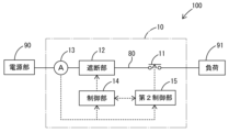
- FIG. 1 is a schematic diagram showing a configuration of an in-vehicle system including an in-vehicle control device according to the first embodiment.
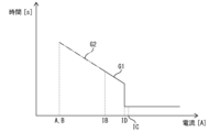
- FIG. 2 is an explanatory diagram showing graphs G1 and G2.
- FIG. 3 is an explanatory diagram showing the corresponding data DA.
- FIG. 4 is an explanatory diagram showing the correspondence data DB.
- FIG. 5 is an explanatory diagram showing the correspondence data DC.
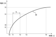
- FIG. 6 is an explanatory diagram showing the TC corresponding data DD.
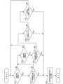
- FIG. 7 is a flowchart showing the flow of the process performed by the control unit.
- An in-vehicle control device included in an in-vehicle system including a power path that supplies power from a power supply unit to a load, a relay provided in the power path, and a breaker provided in the power path, A control unit that controls the interrupter, the cutoff unit switches from a permissive state in which power is permitted to be supplied from the power supply unit side to the load side to a cutoff state in which power is cut off, When a current value flowing through the relay exceeds a threshold, the control unit switches the interrupter to the interrupt state based on an elapsed time since the current value exceeded the threshold and the current value after the current value exceeded the threshold.
- the vehicle control device switches the interrupter to the interrupted state based on the time that has elapsed since the current value flowing through the relay exceeded the threshold and the current value after the threshold was exceeded. In other words, the vehicle control device can switch the interrupter to the interrupted state taking into account the time that has elapsed since the current value flowing through the relay exceeded the threshold and the current value after the threshold was exceeded.
- the vehicle-mounted control device can switch the circuit breaker to the cut-off state when the current value flowing through the relay exceeds a threshold value that is set to a value smaller than the vehicle's maximum rated current.
- threshold value is a value smaller than a maximum interruptable current, which is a maximum current at which the relay can be switched from an on state to an off state.
- the vehicle control device can switch the interrupter to the interrupted state when the current value flowing through the relay exceeds a threshold value that is set to a value smaller than the maximum interruptable current.
- the control unit when the current value exceeds the threshold value, determines whether or not the time integral of the current value after exceeding the threshold value exceeds a corresponding value corresponding to the elapsed time, and switches the cut-off unit to the cut-off state if it determines that the corresponding value has been exceeded.
- the control unit is an in-vehicle control device described in any one of [1] to [3].
- the vehicle control device can switch the cutoff unit to the cutoff state when the time integral of the current value accumulates to a value that exceeds the corresponding value for the elapsed time.
- the control unit when the current value exceeds the threshold value, determines whether or not the time integral of the square of the current value after exceeding the threshold value exceeds a corresponding value corresponding to the elapsed time, and switches the cut-off unit to the cut-off state if it determines that the corresponding value has been exceeded.
- the vehicle control device can switch the cutoff unit to the cutoff state when the time integral of the square of the current value accumulates to a value that exceeds the corresponding value for the elapsed time.
- a cutoff upper limit value is set in advance, the upper limit value being greater than the threshold value and less than a maximum current that can be passed, which is a maximum current that allows the relay to maintain an on-state;
- the vehicle-mounted control device according to any one of [1] to [5], wherein the control unit switches the cutoff unit to the cutoff state regardless of the elapsed time when the current value exceeds the cutoff upper limit value.
- the above-mentioned vehicle-mounted control device switches the circuit breaker to the cut-off state regardless of the amount of time that has passed if the current value flowing through the relay exceeds the upper cut-off limit, making it easier to switch the circuit breaker to the cut-off state before the relay starts to smoke or catch fire.
- the maximum current that can be passed is smaller than a saturation current that flows through the power path when the power path has a ground fault
- the in-vehicle control device wherein the cut-off upper limit value is set taking into account a time lag between when it is determined that the current value has exceeded the cut-off upper limit value and when the cut-off unit switches to the cut-off state, so that the cut-off unit switches to the cut-off state before the current value reaches the saturation current.
- the above-mentioned vehicle-mounted control device can switch the interrupter to the interrupted state before the current value flowing through the relay reaches the saturation current.
- the vehicle control device can switch the cutoff unit to the cutoff state before the current value flowing through the relay reaches the maximum current that can be passed. Therefore, the vehicle control device can avoid a situation in which a current exceeding the maximum current that can be passed through the relay flows, causing the relay to be unable to maintain the on state.
- the relay is controlled by a second control unit different from the control unit,
- the control unit is configured to switch the interrupter to the interrupted state regardless of the elapsed time when the control unit determines that the second control unit has controlled the relay to an off state while the current value exceeds the threshold value.
- the vehicle control device can more reliably interrupt the current flowing through the power path by switching the interrupter to the interruption state when the second control unit attempts to switch the relay to the off state.
- First Embodiment 1 shows an in-vehicle system 100 including an in-vehicle control device 10.
- the in-vehicle system 100 is a system mounted on a vehicle.
- the in-vehicle system 100 includes a power supply unit 90, a load 91, and a power path 80.
- the power supply unit 90 is, for example, a DC power supply that generates a DC voltage, such as a battery.
- the battery is, for example, a lead battery, a lithium ion battery, etc.
- the load 91 is an electronic component provided in the vehicle.
- the load 91 is, for example, an electric component, an ECU, an ADAS target component, etc.
- the power path 80 is provided between the power supply unit 90 and the load 91.
- the power path 80 supplies power from the power supply unit 90 to the load 91.
- One end of the power path 80 is electrically connected to the power supply unit 90, and the other end is electrically connected to the load 91.
- the vehicle control device 10 includes a relay 11, a breaker 12, a current detector 13, a controller 14, and a second controller 15.
- the relay 11 is provided in the power path 80. When the relay 11 is in the on state, a current flows between the power path 80 and the load 91. When the relay 11 is in the off state, a current does not flow between the power path 80 and the load 91.
- the relay 11 is controlled by the second control unit 15.
- the relay 11 is configured as an electromagnetic relay, and has contacts that are operated by electromagnetic force.
- the interrupter 12 is provided in the power path 80.
- the interrupter 12 switches from an allowable state, which allows power to be supplied from the power supply unit 90 to the load 91, to a cutoff state, which cuts off the power.
- the interrupter 12 may be configured to be able to return to an allowable state after being in the cutoff state, or may not be able to return to the allowable state.
- the interrupter 12 is configured, for example, as a pyrotechnic circuit breaker, a semiconductor switch, an electromagnetic fuse, or the like.
- the pyrotechnic circuit breaker is a circuit breaker that physically cuts off the power path 80 in response to the input of a drive signal, and is, for example, a pyrotechnic fuse (PYROFUSE (registered trademark).
- the interrupter 12 is controlled by the control unit 14.
- the current detection unit 13 is configured, for example, as a known current sensor.
- the current detection unit 13 detects the current flowing through the relay 11.
- the current detection unit 13 outputs a signal that can identify the detected value. This signal is input to the control unit 14 and the second control unit 15, respectively.
- the control unit 14 controls the interrupter unit 12.
- the control unit 14 is configured, for example, as an MCU (Micro Controller Unit).
- the control unit 14 is configured as a device separate from the second control unit 15.
- the control unit 14 detects the value of the current flowing through the relay 11 based on the signal output from the current detection unit 13.
- Threshold A is a value smaller than the maximum rated current IA of the vehicle.
- a battery management system that manages power supply unit 90 treats a current that exceeds the maximum rated current IA as an overflow.
- the battery management system treats a current that exceeds the maximum rated current IA as the maximum rated current IA when calculating SOC (State Of Charge).
- SOC State Of Charge
- the control unit 14 determines whether the time integral value ZA of the current value after exceeding the threshold A exceeds a corresponding value CA corresponding to the elapsed time EA, and switches the cutoff unit 12 to the cutoff state if it determines that the time integral value ZA has exceeded the corresponding value CA.
- the control unit 14 pre-stores correspondence data DA indicating the correspondence between the elapsed time EA and the corresponding value CA.
- the correspondence data DA may be a function indicating the correspondence between the elapsed time EA and the corresponding value CA, or may be table data indicating the correspondence between the elapsed time EA and the corresponding value CA.
- the correspondence data DA is set to have the cutoff characteristics shown by graph G1 in Figure 2.
- Graph G1 indicates the time until cutoff when a current of the current value continues to flow for each current value in a predetermined current value range.
- Graph G1 indicates the characteristic that the larger the current value, the shorter the cutoff time.
- the control unit 14 When the current value flowing through the relay 11 exceeds the threshold A, the control unit 14 repeatedly calculates the time integral value ZA of the current value after exceeding the threshold A. For example, as shown in FIG. 3, the control unit 14 first calculates ZA1 as the time integral value ZA. In the next period, the control unit 14 adds ZA2 to the time integral value ZA calculated in the previous period to obtain a new time integral value ZA. By repeating this process, the control unit 14 repeatedly calculates the time integral value ZA. The control unit 14 uses the corresponding data DA to derive the corresponding value CA corresponding to the elapsed time EA. The control unit 14 repeatedly determines whether the time integral value ZA has exceeded the corresponding value CA. In the example shown in FIG.
- the time integral value ZA in the sixth period to which ZA6 is added exceeds the corresponding value CA.
- the control unit 14 determines that the time integral value ZA has exceeded the corresponding value CA, the control unit 14 switches the cutoff unit 12 to the cutoff state.
- the time integral value ZA may be reset to 0 when a first reset condition is met.
- the first reset condition may be that a certain amount of time has elapsed since the value of the current flowing through relay 11 exceeded threshold value A, or that the value of the current flowing through relay 11 has fallen below threshold value A, or may be another condition.
- Threshold B is a value smaller than the maximum interruptible current IB.
- threshold B is the same as threshold A, but it may be greater than or smaller than threshold A.
- the maximum interruptible current IB is the maximum current at which the relay 11 can be switched from an on state to an off state.
- control unit 14 determines whether or not the time integral value ZB of the current value after exceeding threshold B exceeds a corresponding value CB corresponding to elapsed time EB, and switches circuit breaker 12 to the circuit breaker state if it determines that the corresponding value CB has been exceeded.
- Control unit 14 prestores a correspondence data DB indicating the correspondence between elapsed time EB and the corresponding value CB.
- the correspondence data DB may be a function indicating the correspondence between elapsed time EB and the corresponding value CB, or may be table data indicating the correspondence between elapsed time EB and the corresponding value CB.
- the correspondence data DB is set to have the circuit breaker characteristics shown by graph G1 in FIG. 2.
- the control unit 14 When the current value flowing through the relay 11 exceeds the threshold value B, the control unit 14 repeatedly calculates the time integral value ZB of the current value after exceeding the threshold value B. For example, as shown in FIG. 4, the control unit 14 first calculates ZB1 as the time integral value ZB. In the next period, the control unit 14 adds ZB2 to the time integral value ZB calculated in the previous period to obtain a new time integral value ZB. The control unit 14 repeatedly calculates the time integral value ZB by repeating this process. The control unit 14 uses the correspondence data DB to derive the corresponding value CB corresponding to the elapsed time EB. The control unit 14 repeatedly determines whether the time integral value ZB has exceeded the corresponding value CB. In the example shown in FIG.
- the time integral value ZB in the sixth period to which ZB6 is added exceeds the corresponding value CB.
- the control unit 14 determines that the time integral value ZB has exceeded the corresponding value CB, the control unit 14 switches the cutoff unit 12 to the cutoff state.
- the time integral value ZB may be reset to 0 when a second reset condition is met.
- the second reset condition may be that a certain amount of time has elapsed since the value of the current flowing through relay 11 exceeded threshold value B, or that the value of the current flowing through relay 11 has fallen below threshold value B, or may be another condition.
- the second control unit 15 controls the relay 11.
- the second control unit 15 is configured as, for example, an MCU (Micro Controller Unit).
- the second control unit 15 is configured as a device separate from the control unit 14.
- the second control unit 15 switches the relay 11 to the on state when a predetermined start condition is met.
- the start condition is, for example, that the start switch of the vehicle is switched to the on state.
- the start switch is, for example, an ignition switch in an engine vehicle, a power switch in an electric vehicle, etc.
- the second control unit 15 recognizes the on/off state of the start switch of the vehicle, for example, by receiving a signal indicating the on/off state of the start switch of the vehicle.
- the second control unit 15 switches the relay 11 to the off state when a predetermined stop condition is met.
- the stop condition is, for example, that the start switch of the vehicle is switched to the off state.
- the second control unit 15 switches the relay 11 to the off state when a predetermined cut-off condition is met.
- the cut-off condition is, for example, a condition that can be met based on the current value flowing through the relay 11.
- An example of a condition that may be satisfied based on the value of the current flowing through relay 11 is that the value of the current flowing through relay 11 exceeds a reference value.
- the second control unit 15 detects the value of the current flowing through relay 11 based on the signal output from the current detection unit 13.
- the second control unit 15 switches the relay 11 to the OFF state based on the time EC that has elapsed since the reference value was exceeded and the current value after the reference value was exceeded.
- the second control unit 15 determines whether the time integral value ZC of the current value after exceeding the reference value exceeds a corresponding value CC corresponding to the elapsed time EC, and switches the relay 11 to the off state when it is determined that the time integral value ZC has exceeded the corresponding value CC.
- the second control unit 15 prestores correspondence data DC indicating the correspondence between the elapsed time EC and the corresponding value CC.
- the correspondence data DC may be a function indicating the correspondence between the elapsed time EC and the corresponding value CC, or may be table data indicating the correspondence between the elapsed time EC and the corresponding value CC.
- the correspondence data DC is set to have the interruption characteristics shown by graph G2 in FIG. 2.
- Graph G2 indicates the time until interruption when the current of the current value continues to flow for each current value in a predetermined current value range (specifically, a current value range smaller than the lower limit value of the current value range in graph G1).
- Graph G2 indicates the characteristic that the larger the current value, the shorter the time required for interruption.
- the second control unit 15 When the current value flowing through the relay 11 exceeds the reference value, the second control unit 15 repeatedly calculates the time integral value ZC of the current value after exceeding the reference value. For example, as shown in FIG. 5, the second control unit 15 first calculates ZC1 as the time integral value ZC. In the next period, the second control unit 15 adds ZC2 to the time integral value ZC calculated in the previous period to obtain a new time integral value ZC. The second control unit 15 repeatedly calculates the time integral value ZC by repeating this process. The second control unit 15 uses the corresponding data DC to derive the corresponding value CC corresponding to the elapsed time EC. The second control unit 15 repeatedly determines whether the time integral value ZC has exceeded the corresponding value CC. In the example shown in FIG.
- the time integral value ZC in the ninth period to which ZC9 is added exceeds the corresponding value CC.
- the cutoff unit 12 is switched to the cutoff state.
- the time integral value ZC may be reset to 0 when a third reset condition is met.
- the third reset condition may be that a certain amount of time has elapsed since the value of the current flowing through relay 11 exceeded a reference value, or that the value of the current flowing through relay 11 has fallen below a reference value, or it may be another condition.
- the control unit 14 switches the interrupting unit 12 to the interrupted state regardless of the elapsed times EA and EB described above.
- the upper limit ID is greater than the thresholds A and B.
- the upper limit ID is greater than the maximum interruptible current IB.
- the upper limit ID is less than the maximum current IC that can be passed.
- the maximum current IC is the maximum current at which the relay 11 can maintain its on state.
- the relay 11 is an electromagnetic relay. When a current flows through the electromagnetic relay, an electromagnetic repulsive force is generated in the electromagnetic relay to change it from the on state to the off state. This electromagnetic repulsive force increases in accordance with the increase in the magnitude of the current flowing into the electromagnetic relay.
- the electromagnetic repulsive force becomes greater than the force that maintains the electromagnetic relay in the on state, and the electromagnetic relay changes to the off state.
- the electromagnetic relay changes to the off state, an arc is generated in the electromagnetic relay, which may cause the electromagnetic relay to break down. Therefore, when the current value flowing through the relay 11 exceeds the upper cutoff limit ID, which is set to a value smaller than the maximum current IC that can be passed, the control unit 14 switches the cutoff unit 12 to the cutoff state regardless of the elapsed times EA and EB described above.
- the maximum current IC described above is smaller than the saturation current IS that flows through the power path 80 when the power path 80 has a ground fault.
- the saturation current IS is the saturation current when it is assumed that a ground fault occurs in the path between the relay 11 and the load 91 when the power supply unit 90 is fully charged and the in-vehicle system 100 is not degraded.
- the cutoff upper limit ID is set so that the cutoff unit 12 switches to the cutoff state before the current flowing through the relay 11 reaches the saturation current IS, taking into account the time lag TL from when it is determined that the current flowing through the relay 11 has exceeded the cutoff upper limit ID to when the cutoff unit 12 switches to the cutoff state.
- the upper limit ID is set based on, for example, the time lag TL and the TC correspondence data DD (see Figure 6) which indicates the correspondence between the time elapsed since the ground fault occurred and the value of the current flowing through the relay 11.
- the time lag TL is caused by the time from when the control unit 14 determines that the cutoff upper limit ID has been exceeded until it starts control to switch the cutoff unit 12 to the cutoff state, and the time from when control to switch the cutoff unit 12 to the cutoff state starts until the cutoff unit 12 switches to the cutoff state.
- the time lag TL can be obtained, for example, from test results or simulation results.
- the TC correspondence data DD can be obtained, for example, from test results or simulation results.
- the test results or simulation results are, for example, the results when a ground fault is generated in the path between the relay 11 and the load 91 when the in-vehicle system 100 is not degraded and the power supply unit 90 is fully charged.
- the timing at which it is determined that the current value flowing through the relay 11 has reached the saturation current IS may be, for example, the timing when the time elapsed since the occurrence of a ground fault becomes three times the time constant ⁇ , or the timing when 1 ms has elapsed since the occurrence of a ground fault.
- Time constant ⁇ (L1+L2+L3)/(R1+R2+R3)...Formula (1)
- Time constant ⁇ (L1+L2+L3)/(R1+R2+R3)...Formula (1)
- L1 is the internal inductance of the power supply unit 90.
- L2 is the inductance of the path between the power supply unit 90 and the ground fault location in the power path 80.
- L3 is the inductance of the ground fault location.
- R1 is the internal resistance value of the power supply unit 90.
- R2 is the resistance value of the path between the power supply unit 90 and the ground fault location in the power path 80.
- R3 is the resistance value of the ground fault location. Note that L3 and R3 may change depending on the type of ground fault, and may therefore be set to 0, for example.
- timing T1 is identified at which timing T2 after time lag TL has elapsed is earlier than timing T4, and the current value corresponding to this timing T1 is set as the shutoff upper limit ID.
- the upper cutoff value ID is set so that the cutoff unit 12 switches to the cutoff state before the current value flowing through the relay 11 reaches the maximum current IC that can be passed, taking into consideration the time lag TL from when it is determined that the current value flowing through the relay 11 has exceeded the upper cutoff value ID until the cutoff unit 12 switches to the cutoff state.
- the upper cutoff value ID is set, for example, based on the time lag TL and the above-mentioned TC correspondence data DD.
- timing T3 the timing at which the current value flowing through the relay 11 reaches the maximum current IC that can be passed is set to timing T3.
- the current value corresponding to timing T1 which does not reach timing T3 even when time lag TL is taken into account, is set as the shutoff upper limit ID.
- timing T1 at which timing T2 after time lag TL has elapsed is earlier than timing T3 is identified, and the current value corresponding to this timing T1 is set as the shutoff upper limit ID.
- the upper cutoff limit ID is set to a value greater than the maximum current value IE that can flow through the power path 80 when the power path 80 is in a normal state.
- the normal state of the power path 80 means that the power path 80 is not faulted to ground, and more specifically, that the voltage value of the power path 80 is equal to or greater than the threshold voltage.
- the threshold voltage is a value of 0V or greater.
- the maximum current value IE that can flow through the power path 80 is, for example, the current that flows through the power path 80 when a load 91, such as a motor in a vehicle, is operated at maximum capacity when the power source unit 90 is fully charged.
- the control unit 14 determines that the second control unit 15 has controlled the relay 11 to the off state when the value of the current flowing through the relay 11 exceeds threshold A, the control unit 14 switches the breaker unit 12 to the off state regardless of the elapsed time EA.
- the control unit 14 determines that the second control unit 15 has controlled the relay 11 to the off state when the value of the current flowing through the relay 11 exceeds threshold B, the control unit 14 switches the breaker unit 12 to the off state regardless of the elapsed time EB.
- the second control unit 15 outputs, for example, a control signal to control the relay 11 to the off state and also outputs a notification signal to the control unit 14. By receiving the notification signal, the control unit 14 determines that the second control unit 15 has controlled the relay 11 to the off state.
- the control unit 14 performs the process shown in FIG. 7 when, for example, the start switch of the vehicle is switched to the off state.
- step S11 the control unit 14 determines whether the value of the current flowing through the relay 11 is greater than threshold A. If the control unit 14 determines that the value of the current flowing through the relay 11 is not greater than threshold A, then in step S14, the control unit 14 determines whether the value of the current flowing through the relay 11 is greater than threshold B. If the control unit 14 determines that the value of the current flowing through the relay 11 is not greater than threshold B, the control unit 14 returns to step S11. If the value of the current flowing through the relay 11 is normal, the control unit 14 repeats the processes of steps S11 and S14.
- step S11 the control unit 14 determines in step S11 that the current value flowing through the relay 11 is greater than the threshold value A, it starts calculating the time integral value ZA and proceeds to step S12. If the control unit 14 has already calculated the time integral value ZA, it continues calculating the time integral value ZA. In step S12, the control unit 14 determines whether the time integral value ZA is greater than the corresponding value CA corresponding to the time integral value ZA. If the control unit 14 determines that the time integral value ZA is greater than the corresponding value CA, it switches the cutoff unit 12 to the cutoff state in step S13. If the control unit 14 determines that the time integral value ZA is not greater than the corresponding value CA, it proceeds to step S14.
- step S14 determines in step S14 that the current value flowing through the relay 11 is greater than the threshold value B, it starts calculating the time integral value ZB and proceeds to step S15. If the control unit 14 has already calculated the time integral value ZB, it continues calculating the time integral value ZB. In step S15, the control unit 14 determines whether the time integral value ZB is greater than the corresponding value CB corresponding to the time integral value ZB. If the control unit 14 determines that the time integral value ZB is not greater than the corresponding value CB, it determines in step S16 whether the control unit 14 has controlled the relay 11 to the OFF state.
- control unit 14 determines in step S17 whether the current value flowing through the relay 11 is greater than the interruption upper limit ID. If the control unit 14 determines that the current value flowing through the relay 11 is not greater than the interruption upper limit ID, it returns to step S11. In other words, when the value of the current flowing through the relay 11 exceeds the threshold value B, the control unit 14 repeats the processes of steps S14, S15, S16, and S17.
- control unit 14 determines in step S15 that the time integral value ZB is greater than the corresponding value CB, it switches the cutoff unit 12 to the cutoff state in step S13. If the control unit 14 determines in step S16 that it has controlled the relay 11 to the off state, it switches the cutoff unit 12 to the cutoff state in step S13. If the control unit 14 determines in step S17 that the current value flowing through the relay 11 is greater than the cutoff upper limit value ID, it switches the cutoff unit 12 to the cutoff state in step S13.
- the vehicle control device 10 switches the breaker 12 to the cut-off state based on the elapsed time EA since the current value flowing through the relay 11 exceeded the threshold A and the current value after exceeding the threshold A. That is, the vehicle control device 10 can switch the breaker 12 to the cut-off state taking into consideration the elapsed time EA since the current value flowing through the relay 11 exceeded the threshold A and the current value after exceeding the threshold A. Furthermore, the vehicle control device 10 can switch the breaker 12 to the cut-off state when the time integral value ZA of the current value is accumulated to an extent that exceeds a corresponding value CA corresponding to the elapsed time EA.
- the vehicle control device 10 switches the interrupter 12 to the interrupted state based on the time EB that has elapsed since the current value flowing through the relay 11 exceeded the threshold B and the current value after exceeding the threshold B.
- the vehicle control device 10 can switch the interrupter 12 to the interrupted state taking into account the time EB that has elapsed since the current value flowing through the relay 11 exceeded the threshold B and the current value after exceeding the threshold B.
- the vehicle control device 10 can switch the interrupter 12 to the interrupted state when the time integral value ZB of the current value has accumulated to an extent that it exceeds the corresponding value CB that corresponds to the elapsed time EB.
- the vehicle control device 10 switches the cutoff unit 12 to the cutoff state regardless of the elapsed time EB, making it easier to switch the cutoff unit 12 to the cutoff state before the relay 11 can no longer maintain the on state.
- the vehicle control device 10 can switch the cutoff unit 12 to the cutoff state before the current value flowing through the relay 11 reaches the saturation current IS.
- the vehicle control device 10 can switch the cutoff unit 12 to the cutoff state before the value of the current flowing through the relay 11 reaches the maximum current IC that can be passed through the relay. Therefore, the vehicle control device 10 can prevent a current exceeding the maximum current IC from flowing through the relay 11, causing the relay 11 to be unable to maintain the on state.
- the relay 11 may not switch to the OFF state due to a malfunction of the relay 11 or the like. Even if such a situation occurs, the in-vehicle control device 10 can more reliably interrupt the current flowing through the power path 80 by switching the interrupter 12 to the interruption state when the second control unit 15 attempts to switch the relay 11 to the OFF state.
- the control unit 14 determines whether or not the time integral value ZA of the current value since exceeding the threshold A exceeds a corresponding value CA corresponding to the elapsed time EA, and switches the cutoff unit 12 to the cutoff state if it determines that the corresponding value CA has been exceeded.
- the control unit 14 may be configured to determine whether or not the time integral value of the square of the current value since exceeding the threshold A exceeds a corresponding value corresponding to the elapsed time EA, when the current value flowing through the relay 11 exceeds the threshold A, and switches the cutoff unit 12 to the cutoff state if it determines that the corresponding value has been exceeded.
- the vehicle control device can switch the cutoff unit 12 to the cutoff state when the time integral value of the square of the current value has accumulated to an extent that exceeds the corresponding value corresponding to the elapsed time EA.
- the control unit 14 determines whether or not the time integral value ZA of the current value since exceeding the threshold B exceeds a corresponding value CB corresponding to the elapsed time EB, and switches the cutoff unit 12 to the cutoff state if it determines that the corresponding value CB has been exceeded.
- the control unit 14 may be configured to determine whether or not the time integral value of the square of the current value since exceeding the threshold B exceeds a corresponding value corresponding to the elapsed time EB, when the current value flowing through the relay 11 exceeds the threshold B, and switches the cutoff unit 12 to the cutoff state if it determines that the corresponding value has been exceeded.
- the vehicle control device can switch the cutoff unit 12 to the cutoff state when the time integral value of the square of the current value has accumulated to an extent that exceeds the corresponding value corresponding to the elapsed time EB.
- the upper cutoff limit does not need to be set. In other words, the process of step S16 in FIG. 7 may be omitted.
- One of threshold A and threshold B may be omitted. In other words, one of steps S11, S12 and steps S14, S15 in FIG. 7 may be omitted.
- the upper cutoff limit ID is greater than the maximum cutoff current IB, but it may be less than the maximum cutoff current IB.
- a fuse may be provided between the power supply unit 90 and the current detection unit 13.
Landscapes
- Engineering & Computer Science (AREA)
- Mechanical Engineering (AREA)
- Life Sciences & Earth Sciences (AREA)
- Sustainable Development (AREA)
- Sustainable Energy (AREA)
- Power Engineering (AREA)
- Transportation (AREA)
- Emergency Protection Circuit Devices (AREA)
Abstract
L'invention concerne un dispositif de commande embarqué (10) qui est compris dans un système embarqué (100) qui comprend : une voie de transmission d'électricité (80) pour l'alimentation en électricité, par une unité d'alimentation électrique (90), d'une charge (91) ; un relais (11) ménagé sur la voie de transmission d'électricité (80) ; et une unité disjoncteur (12) ménagée sur la voie de transmission d'électricité (80). Le dispositif de commande embarqué (10) est muni d'une unité de commande (14) qui commande l'unité disjoncteur (12). L'unité disjoncteur (12) passe d'un état admissible, dans lequel l'électricité est permise d'alimenter, par le côté unité d'alimentation électrique (90), le côté charge (91), à un état de coupure, dans lequel l'électricité est coupée. Si la valeur d'un courant circulant à travers le relais (11) atteint ou dépasse une valeur seuil, l'unité de commande (14) fait passer l'unité disjoncteur (12) vers l'état de coupure sur la base du temps écoulé et de la valeur de courant après que la valeur seuil a été atteinte ou dépassée.
Priority Applications (3)
| Application Number | Priority Date | Filing Date | Title |
|---|---|---|---|
| CN202380062232.7A CN119790557A (zh) | 2023-06-06 | 2023-06-06 | 车载用控制装置 |
| JP2023576378A JP7491484B1 (ja) | 2023-06-06 | 2023-06-06 | 車載用制御装置 |
| PCT/JP2023/021002 WO2024252519A1 (fr) | 2023-06-06 | 2023-06-06 | Dispositif de commande embarqué |
Applications Claiming Priority (1)
| Application Number | Priority Date | Filing Date | Title |
|---|---|---|---|
| PCT/JP2023/021002 WO2024252519A1 (fr) | 2023-06-06 | 2023-06-06 | Dispositif de commande embarqué |
Publications (1)
| Publication Number | Publication Date |
|---|---|
| WO2024252519A1 true WO2024252519A1 (fr) | 2024-12-12 |
Family
ID=91194175
Family Applications (1)
| Application Number | Title | Priority Date | Filing Date |
|---|---|---|---|
| PCT/JP2023/021002 Ceased WO2024252519A1 (fr) | 2023-06-06 | 2023-06-06 | Dispositif de commande embarqué |
Country Status (3)
| Country | Link |
|---|---|
| JP (1) | JP7491484B1 (fr) |
| CN (1) | CN119790557A (fr) |
| WO (1) | WO2024252519A1 (fr) |
Citations (3)
| Publication number | Priority date | Publication date | Assignee | Title |
|---|---|---|---|---|
| JPS5475347U (fr) * | 1977-11-08 | 1979-05-29 | ||
| JPH07123504A (ja) * | 1993-10-19 | 1995-05-12 | Matsushita Electric Works Ltd | 電気自動車用安全装置 |
| WO2006059646A1 (fr) * | 2004-11-30 | 2006-06-08 | Autonetworks Technologies, Ltd. | Dispositif de commande d'alimentation |
-
2023
- 2023-06-06 CN CN202380062232.7A patent/CN119790557A/zh active Pending
- 2023-06-06 JP JP2023576378A patent/JP7491484B1/ja active Active
- 2023-06-06 WO PCT/JP2023/021002 patent/WO2024252519A1/fr not_active Ceased
Patent Citations (3)
| Publication number | Priority date | Publication date | Assignee | Title |
|---|---|---|---|---|
| JPS5475347U (fr) * | 1977-11-08 | 1979-05-29 | ||
| JPH07123504A (ja) * | 1993-10-19 | 1995-05-12 | Matsushita Electric Works Ltd | 電気自動車用安全装置 |
| WO2006059646A1 (fr) * | 2004-11-30 | 2006-06-08 | Autonetworks Technologies, Ltd. | Dispositif de commande d'alimentation |
Also Published As
| Publication number | Publication date |
|---|---|
| JPWO2024252519A1 (fr) | 2024-12-12 |
| JP7491484B1 (ja) | 2024-05-28 |
| CN119790557A (zh) | 2025-04-08 |
Similar Documents
| Publication | Publication Date | Title |
|---|---|---|
| JP6304784B2 (ja) | バッテリモジュール遮断構造 | |
| JP6623937B2 (ja) | リレー装置及び電源装置 | |
| JP6677250B2 (ja) | 直流回路、直流電力供給装置、移動体及び電力供給システム | |
| US20170187179A1 (en) | Junction box | |
| CN114430877B (zh) | 电流断路装置以及电流断路方法 | |
| CN113644621B (zh) | 汽车电路保护装置、系统和方法 | |
| JP2023174919A (ja) | 車載用制御装置 | |
| JP7491484B1 (ja) | 車載用制御装置 | |
| JP5443013B2 (ja) | バッテリー保護回路及びバッテリー装置 | |
| JP7710344B2 (ja) | 電源制御装置および電源制御方法 | |
| JP7723903B2 (ja) | 遮断制御装置 | |
| US20240274385A1 (en) | Switching arrangement and method for operating a switching arrangement | |
| JP7755800B2 (ja) | 遮断制御装置 | |
| JP2008148419A (ja) | パック電池 | |
| WO2023152786A1 (fr) | Dispositif de commande d'arrêt embarqué | |
| JP7616482B2 (ja) | 車載用遮断電流供給装置 | |
| WO2025069144A1 (fr) | Dispositif de coupure embarqué | |
| JP7571811B2 (ja) | 開閉制御装置および車両 | |
| WO2025215741A1 (fr) | Dispositif de commande embarqué | |
| WO2024100793A1 (fr) | Dispositif de commande d'arrêt de véhicule | |
| WO2025069142A1 (fr) | Dispositif d'arrêt embarqué | |
| WO2018146942A1 (fr) | Dispositif de suppression d'arc | |
| WO2024100775A1 (fr) | Dispositif de protection de véhicule | |
| WO2024100773A1 (fr) | Dispositif de commande d'interruption de véhicule | |
| WO2025158637A1 (fr) | Dispositif de commande embarqué |
Legal Events
| Date | Code | Title | Description |
|---|---|---|---|
| WWE | Wipo information: entry into national phase |
Ref document number: 2023576378 Country of ref document: JP |
|
| 121 | Ep: the epo has been informed by wipo that ep was designated in this application |
Ref document number: 23940624 Country of ref document: EP Kind code of ref document: A1 |
|
| WWE | Wipo information: entry into national phase |
Ref document number: 202380062232.7 Country of ref document: CN |
|
| WWP | Wipo information: published in national office |
Ref document number: 202380062232.7 Country of ref document: CN |
|
| NENP | Non-entry into the national phase |
Ref country code: DE |