WO2024252523A1 - 置局設計装置、置局設計方法、及びプログラム - Google Patents
置局設計装置、置局設計方法、及びプログラム Download PDFInfo
- Publication number
- WO2024252523A1 WO2024252523A1 PCT/JP2023/021024 JP2023021024W WO2024252523A1 WO 2024252523 A1 WO2024252523 A1 WO 2024252523A1 JP 2023021024 W JP2023021024 W JP 2023021024W WO 2024252523 A1 WO2024252523 A1 WO 2024252523A1
- Authority
- WO
- WIPO (PCT)
- Prior art keywords
- design
- wireless communication
- value
- station
- placement
- Prior art date
- Legal status (The legal status is an assumption and is not a legal conclusion. Google has not performed a legal analysis and makes no representation as to the accuracy of the status listed.)
- Ceased
Links
Images


Classifications
-
- H—ELECTRICITY
- H04—ELECTRIC COMMUNICATION TECHNIQUE
- H04W—WIRELESS COMMUNICATION NETWORKS
- H04W16/00—Network planning, e.g. coverage or traffic planning tools; Network deployment, e.g. resource partitioning or cells structures
- H04W16/24—Cell structures
Definitions
- This disclosure relates to design techniques for installing wireless communication base stations.
- station placement design is carried out to determine the installation location of base stations and the direction of antennas.
- methods such as the ray tracing method (Non-Patent Document 1) are used to perform a simulation evaluation of the coverage area.
- the present invention was made in consideration of the above points, and aims to perform appropriate station placement design according to the intended use.
- the invention of claim 1 is a station placement design device that designs the placement of a wireless communication base station, and has a selection unit that selects a top predetermined number of wireless communication devices that have a high second design value considered when performing the design among multiple candidate wireless communication devices to be installed as the base station and whose first design value considered when performing the design satisfies a first target value.
- the present invention has the effect of enabling appropriate station placement design depending on the intended use.
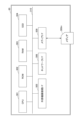
- FIG. 1 is an overall configuration diagram of a communication system according to an embodiment.
- FIG. 2 is an electrical hardware configuration diagram of the station design apparatus according to the embodiment.
- FIG. 2 is a diagram illustrating an electrical hardware configuration of a communication terminal according to the embodiment.
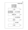
- FIG. 2 is a functional configuration diagram of a station design device according to an embodiment.
- FIG. 1 is a conceptual diagram of an area subject to station placement design. 4 is a flowchart showing a station placement design method executed by the station placement design device according to the embodiment. 1 is a flowchart showing a station placement design method executed by a station placement design device according to an embodiment.
- the communication system 10 of the embodiment is constructed by a station placement design device 30 and a communication terminal 50.
- the communication terminal 50 is managed and used by a user.
- the user refers to the output result of the station placement design device 30 and decides on the next action to be taken.
- the station design device 30 and the communication terminal 50 can communicate with each other via a communication network 100 such as the Internet.
- the connection form of the communication network 100 may be either wireless or wired.
- the station placement design device 30 is composed of one or more computers. When the station placement design device 30 is composed of multiple computers, it may be referred to as a "station placement design device” or a "station placement design system.”
- the station placement design device 30 is a device that designs the installation of wireless communication base stations, and performs more appropriate station placement design by selecting an appropriate wireless communication device from candidates for wireless communication devices (5G antennas, Wi-Fi APs (Access Points), etc.) to be installed as a base station according to the intended use.
- 5G antennas, Wi-Fi APs (Access Points), etc. 5G antennas, Wi-Fi APs (Access Points), etc.
- the communication terminal 50 is a computer, and FIG. 1 shows a notebook computer as an example.
- a user operates the communication terminal 50.
- the station design device 30 may perform processing alone, without using the communication terminal 50.
- FIG. 2 is a diagram showing the electrical hardware configuration of the station placement design device.
- the SSD 304 reads and writes various data according to the control of the CPU 301. Note that a HDD (Hard Disk Drive) may be used instead of the SSD 304.
- HDD Hard Disk Drive
- the media I/F 309 controls the reading and writing (storing) of data to a recording medium 309m such as a flash memory.
- Recording media 309m includes DVDs (Digital Versatile Discs) and Blu-ray Discs (registered trademarks).
- the "design environment information” includes information showing the size of the area for which the station is designed, the size and location of structures, whether or not there is obstruction, a 3D map of the area, etc.
- the "design condition information” includes information indicating the type of wireless communication method (5G, Wi-Fi, etc.) to be installed as a base station, the number of base stations that can be installed (inventory number, etc.), the positions (candidate base station installation positions) and directions in which base stations can be installed within the area targeted for station design, the evaluation positions for communication quality (signal strength) within the area targeted for station design, and the design derivation mode, etc.
- the "wireless communication method” may also be simply referred to as the "communication method.”
- the "design derivation modes" include a cost priority mode, a communication quality priority mode, and a cost and communication quality compatible mode, and are set in advance according to the purpose of use of the wireless communication device in each station design target area.
- the cost priority mode is set for an area in an office where a PC or the like is operated
- the communication quality priority mode is set for an area where a robot is remotely operated by remote control
- the compatible mode is set for an area in an office where a robot is remotely operated.
- the station design target area may, for example, be one floor of a building or a location section of an outdoor exhibition hall. Also, for example, one floor may be divided into multiple areas and a different mode may be set for each area.
- the "design target information” includes communication quality such as radio wave strength (also called “received power”) and equipment cost for each type of wireless communication device (5G, Wi-Fi, etc.).
- the equipment cost is the unit price of the wireless communication device, but may also include the installation cost of the wireless communication device.
- each piece of information included in the design environment information, design condition information, and design goal information may be other than the examples given above.
- the design goal information may include the operating cost of the equipment (power consumption, etc.) and a target value for this operating cost in addition to or instead of the equipment cost.
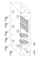
- FIG. 5 is a conceptual diagram of the station placement design target area.
- an indoor area is described, but an outdoor area may also be used.
- multiple installation position candidates c1 to c6 are set at various points on the ceiling, radio wave quality evaluation positions e1 at various points on the floor, and structures s1, etc.
- the throughput may be predicted from a conversion table of received power and throughput that is prepared in advance by acquiring experimental data or by link level simulation, for example.
- the selection unit 35 judges whether there is one or more design result candidates in which each design value (equipment cost, communication quality value) satisfies all of the target values (equipment cost target value, communication quality target value) included in the design target information. That is, the selection unit 35 judges whether there is one or more design result candidates in which the design value (equipment cost) satisfies the equipment cost target value and the design value (communication quality value) satisfies the communication quality target value.
- the selection unit 35 selects a design result candidate that satisfies all of the target values included in the design goal information. From the selected design result candidates, the selection unit 35 selects a specific wireless communication device that is a top predetermined number of design results with the highest inverse of device cost or communication quality value based on the priority between the target information included in the design goal information. For example, in an area where a robot is remotely operated, the communication quality has the highest priority, and the device cost has the second highest priority. Also, in an area where a PC (Personal Computer) or the like is operated in an office, the device cost has the highest priority, and the communication quality has the second highest priority.
- PC Personal Computer
- f c (c(i)) 0 (c(i) ⁇ c t )
- f c (c(i)) ⁇ (c(i)> c t )
- the selection unit 35 calculates each communication quality evaluation function f q (q(i)) that satisfies the target value of the communication quality and each cost evaluation function f c (c(i)) that indicates the cost corresponding to each f q (q(i)), as shown below.
- the selection unit 35 selects a top predetermined number of design results from the selected design result candidates that have the highest design value for the inverse of the device cost or the highest design value for communication quality, based on the priority order between the goal information included in the design goal information.
- the selection unit 35 calculates each total satisfaction level (T s (i)), and selects a top predetermined number of T s (i) having the highest total satisfaction level (T s (i)) as the design result.
- the selection unit 35 selects a top predetermined number of wireless communication devices from among multiple candidate wireless communication devices to be installed as base stations, which have the highest sum of the first target value achievement degree (e.g., achievement degree below a predetermined value) of a first design value (e.g., device cost or operating cost) taken into account when performing the design and the second target value achievement degree (e.g., achievement degree above a predetermined value) of a second design value (e.g., communication quality) taken into account when performing the design.
- a first target value achievement degree e.g., achievement degree below a predetermined value
- a first design value e.g., device cost or operating cost
- the second target value achievement degree e.g., achievement degree above a predetermined value
- a second design value e.g., communication quality
Landscapes
- Engineering & Computer Science (AREA)
- Computer Networks & Wireless Communication (AREA)
- Signal Processing (AREA)
- Mobile Radio Communication Systems (AREA)
Abstract
本開示の目的は、使用目的に応じて適切な置局設計を行うことを目的とする。 そのため、本開示は、無線通信の基地局の設置に関する設計を行う置局設計装置であって、前記基地局として設置すべき複数の無線通信装置の候補において、前記設計を行う場合に考慮する第1の設計値が第1の目標値を満たしたうちで、前記設計を行う場合に考慮する第2の設計値が高い上位所定数の前記無線通信装置の選択処理を行う選択部を有する置局設計装置である。
Description
本開示は、無線通信の基地局を設置する際の設計技術に関する。
一般的に、セルラーや無線LAN(Local Area Network)等の無線通信のカバーエリアを構築するため、基地局の設置位置やアンテナ方向を決める置局設計が行われる。置局設計では、基地局の配置を選定した上で、カバーエリアのシミュレーション評価を行う際、レイトレーシング法(非特許文献1)などの方法が用いられる。
また、遠隔制御によりロボットを遠隔操作する場合には電波強度等の通信品質が優先され、カフェや店舗等の利用者向けのインターネット接続環境を提供する場合にはコストが優先されることが考えられる。そのため、使用目的に応じて、基地局として設置すべき無線通信装置の種類を選択して置局設計すべきとのニーズがある。
NTT DoCoMoテクニカルジャーナル vol.15 no.3<https://www.nttdocomo.co.jp/binary/pdf/corporate/technology/rd/technical_journal/bn/vol15_3/vol15_3_020jp.pdf>
しかしながら、非特許文献1に示すような従来技術では、使用目的に応じて適切な置局設計を行うことが困難であった。
本発明は、上述の点に鑑みてなされたものであって、使用目的に応じて適切な置局設計を行うことを目的とする。
上記課題を解決するため、請求項1に係る発明は、無線通信の基地局の設置に関する設計を行う置局設計装置であって、前記基地局として設置すべき複数の無線通信装置の候補において、前記設計を行う場合に考慮する第1の設計値が第1の目標値を満たしたうちで、前記設計を行う場合に考慮する第2の設計値が高い上位所定数の前記無線通信装置の選択処理を行う選択部を有する置局設計装置である。
以上説明したように本発明によれば、使用目的に応じて適切な置局設計を行うことができるという効果を奏する。
以下、図面に基づいて本発明の実施形態を説明する。
〔実施形態のシステム構成〕
まず、図1を用いて、実施形態の通信システムの全体構成について説明する。図1は、本施形態に係る通信システムの全体構成図である。
まず、図1を用いて、実施形態の通信システムの全体構成について説明する。図1は、本施形態に係る通信システムの全体構成図である。
図1に示されているように、実施形態の通信システム10は、置局設計装置30、及び通信端末50によって構築されている。通信端末50は、ユーザによって管理及び使用される。ユーザは、置局設計装置30の出力結果を参照して、その後の対応を判断する者である。
また、置局設計装置30と通信端末50は、インターネット等の通信ネットワーク100を介して通信することができる。通信ネットワーク100の接続形態は、無線又は有線のいずれでも良い。
置局設計装置30は、単数又は複数のコンピュータによって構成されている。置局設計装置30が複数のコンピュータによって構成されている場合には、「置局設計装置」と示しても良いし、「置局設計システム」と示しても良い。置局設計装置30は、無線通信の基地局の設置に関する設計を行う装置であり、基地局として設置すべき無線通信装置(5Gのアンテナ、Wi-FiのAP(Access Point)等)の候補のうち、使用目的に応じて適切な無線通信装置を選択することで、より適切な置局設計を行う。
通信端末50は、コンピュータであり、図1では、一例としてノート型パソコンが示されている。図1では、ユーザが、通信端末50を操作する。なお、通信端末50を用いずに、置局設計装置30単独で処理をしてもよい。
〔ハードウェア構成〕
<置局設計装置のハードウェア構成>
次に、図2を用いて、置局設計装置30の電気的なハードウェア構成を説明する。図2は、置局設計装置の電気的なハードウェア構成図である。
<置局設計装置のハードウェア構成>
次に、図2を用いて、置局設計装置30の電気的なハードウェア構成を説明する。図2は、置局設計装置の電気的なハードウェア構成図である。
置局設計装置30は、コンピュータとして、図2に示されているように、プロセッサとしてのCPU(Central Processing Unit)301、ROM(Read Only Memory)302、RAM(Random Access Memory)303、SSD(Solid State Drive)304、外部機器接続I/F(Interface)305、ネットワークI/F306、メディアI/F309、及びバスライン310を備えている。
これらのうち、CPU301は、置局設計装置30全体の動作を制御する。ROM302は、IPL(Initial Program Loader)等のCPU301の駆動に用いられるプログラムを記憶する。RAM303は、CPU301のワークエリアとして使用される。
SSD304は、CPU301の制御に従って各種データの読み出し又は書き込みを行う。なお、SSD304の代わりに、HDD(Hard Disk Drive)を用いても良い。
外部機器接続I/F305は、各種の外部機器を接続するためのインターフェースである。この場合の外部機器は、ディスプレイ、スピーカ、キーボード、マウス、USB(Universal Serial Bus)メモリ、及びプリンタ等である。
ネットワークI/F306は、通信ネットワーク100を介してデータ通信をするためのインターフェースである。
メディアI/F309は、フラッシュメモリ等の記録メディア309mに対するデータの読み出し又は書き込み(記憶)を制御する。記録メディア309mには、DVD(Digital Versatile Disc)やBlu-ray Disc(登録商標)等も含まれる。
バスライン310は、図2に示されているCPU301等の各構成要素を電気的に接続するためのアドレスバスやデータバス等である。
<通信端末のハードウェア構成>
次に、図3を用いて、通信端末50の電気的なハードウェア構成を説明する。図3は、通信端末の電気的なハードウェア構成図である。
次に、図3を用いて、通信端末50の電気的なハードウェア構成を説明する。図3は、通信端末の電気的なハードウェア構成図である。
通信端末50は、コンピュータとして、図3に示されているように、CPU501、ROM502、RAM503、SSD504、外部機器接続I/F(Interface)505、ネットワークI/F506、ディスプレイ507、入力デバイス508、メディアI/F509、及びバスライン510を備えている。
これらのうち、CPU501は、通信端末50全体の動作を制御する。ROM502は、IPL等のCPU501の駆動に用いられるプログラムを記憶する。RAM503は、CPU501のワークエリアとして使用される。
SSD504は、CPU501の制御に従って各種データの読み出し又は書き込みを行う。なお、SSD504の代わりに、HDD(Hard Disk Drive)を用いてもよい。
外部機器接続I/F505は、各種の外部機器を接続するためのインターフェースである。この場合の外部機器は、ディスプレイ、スピーカ、キーボード、マウス、USBメモリ、及びプリンタ等である。
ネットワークI/F506は、通信ネットワーク100を介してデータ通信をするためのインターフェースである。
ディスプレイ507は、各種画像を表示する液晶や有機EL(Electro Luminescence)などの表示手段の一種である。
入力デバイス508は、キーボード、ポインティングデバイス等であり、各種指示の選択や実行、処理対象の選択、カーソルの移動などを行う入力手段の一種である。なお、ユーザがキーボードを使う場合は、ポインティングデバイスの機能をOFFにしてもよい。
メディアI/F509は、フラッシュメモリ等の記録メディア509mに対するデータの読み出し又は書き込み(記憶)を制御する。記録メディア509mには、DVDやBlu-ray Disc(登録商標)等も含まれる。
バスライン510は、図3に示されているCPU501等の各構成要素を電気的に接続するためのアドレスバスやデータバス等である。
〔実施形態の機能構成〕
図4は、実施形態に係る置局設計装置の機能構成図である。
図4は、実施形態に係る置局設計装置の機能構成図である。
図4に示すように、置局設計装置30は、入力部31、候補抽出部33、選択部35、及び出力部37を有している。これら各部は、プログラムに基づき図2のCPU301による命令によって実現される機能である。
<入力部>
入力部31は、通信端末50から、設計環境情報、設計条件情報、及び設計目標情報を入力する。
入力部31は、通信端末50から、設計環境情報、設計条件情報、及び設計目標情報を入力する。
「設計環境情報」には、置局設計対象エリアの広さ、構造物の大きさや位置、遮蔽の有無、エリアの3Dマップ等を示す情報が含まれている。
「設計条件情報」には、基地局として設置される無線通信方式の種類(5G、Wi-Fi等)、基地局の設置可能数(在庫数等)、置局設計対象エリア内で基地局を設置可能な位置(基地局の設置位置候補)及び方向、置局設計対象エリア内における通信品質(電波強度)の評価位置、並びに設計導出モード等を示す情報等が含まれている。なお、本実施形態では、「無線通信方式」は単に「通信方式」と示す場合もある。
なお、「設計導出モード」には、コスト優先モード、通信品質優先モード、並びに、コスト及び通信品質の両立モードが含まれており、各置局設計対象エリアでの無線通信装置の使用目的に応じて予め設定されている。例えば、オフィスでPC等を操作するエリアの場合にはコスト優先モード、遠隔制御によりロボットを遠隔操作するエリア場合には通信品質優先モード、オフィスでもロボットを遠隔操作するエリアの場合には両立モードが設定されている。なお、置局設計対象エリアは、例えば、ビルの1フロア、野外の展示場の位置区画等を示す。また、例えば、1フロアを複数のエリアに分割し、エリア毎に異なるモードが設定されていてもよい。
「設計目標情報」には、無線通信装置の種類(5G用、Wi-Fi用等)毎に、電波強度(「受信電力」ともいう)等の通信品質及び装置コストが含まれている。装置コストは、無線通信装置の単価であるが、無線通信装置の設置コストが含まれていてもよい。
更に、「設計目標情報」には、置局設計を行う際の目標値(電波強度等の通信品質の目標値、装置コストの目標値)、及び通信品質及び装置コストを用いて計算する場合の優先順位等を示す情報が含まれる。例えば、通信方式が5Gの場合、電波強度(RSRP:Reference Signal Received Power)の目標値は「-105dBm」、装置コストの目標値は「1000万円」である。また、通信方式がWi-Fiの場合、電波強度(RSSI;Received Signal Strength Indicator)の目標値は「-75dBm」、装置コストの目標値は「100万円」である。
なお、設計環境情報、設計条件情報、及び設計目標情報に含まれている各情報は、上記の例以外であってもよい。例えば、設計目標情報には、装置コストに加えて又は装置コストに代えて、装置の運用コスト(消費電力等)とこの運用コストの目標値が含まれていてもよい。
<候補抽出部>
候補抽出部33は、入力部31から取得した設計環境情報及び設計条件情報に基づき、置局設計対象エリア内において、どの設置位置候補にどの無線通信装置を設置すると、どの程度の通信品質になるかを算出することで、複数(i=1,2,…,I)の置局設計結果候補を算出する。
候補抽出部33は、入力部31から取得した設計環境情報及び設計条件情報に基づき、置局設計対象エリア内において、どの設置位置候補にどの無線通信装置を設置すると、どの程度の通信品質になるかを算出することで、複数(i=1,2,…,I)の置局設計結果候補を算出する。
ここで、図5を用いて、置局設計対象エリアについて説明する。図5は、置局設計対象エリアの概念図である。図5では、屋内のエリアについて説明するが、屋外のエリアであってもよい。図5に示すように、置局設計対象エリア内には、天井の各所における複数の設置位置候補c1~c6、床の各所における電波品質の評価位置e1等、及び構造物s1等が設定されている。
なお、設置位置候補c1~c6の総称を「設置位置候補c」と示す。評価位置e1等の総称を「評価位置e」と示す。また、構造物s1等の総称を「構造物s」と示す。また、図5に示す設置位置候補c、評価位置e、及び構造物sの各数は一例であって、図5に示されている数に限らない。
実施形態の置局設計装置30は、複数の設置位置候補cから、5Gの基地局に最適な設置位置候補cを1つ又は複数選択する。また、置局設計装置30は、複数の設置位置候補cから、Wi-Fiの基地局に最適な設置位置候補cを1つ又は複数選択してもよい。
続いて、図4に戻り、候補抽出部33は、3Dモデルを用いたレイトレーシング等の電波伝搬推定(シミュレーション)を行うことで、受信電力(電波強度)を推定する。具体的には、候補抽出部33は、設計環境情報及び設計条件情報に基づいて、所定の設置位置候補で所定の設置方向に設置された場合の所定の種類の5Gのアンテナの各組合せに係る各基地局から、5Gの電波が受信可能な各評価位置に対する電波伝搬推定を行うことで、各組合せに対する各評価位置での受信電力を推定する。または、候補抽出部33は、設計環境情報及び設計条件情報に基づいて、所定の設置位置候補で所定の設置方向に設置された場合の所定の種類のAPの装置の各組合せに係る基地局から、Wi-Fiの電波が受信可能な各評価位置に対する電波伝搬推定を行うことで、各組合せに対する各評価位置での受信電力を推定する。例えば、天井の設置位置候補が6つで、設置方向が4方向で、5Gのアンテナの種類が2つで、床の評価位置が10カ所の場合、候補抽出部33は、480回(=6×4×2×10)の計算により受信電力を推定する。また、天井の設置位置候補が6つで、設置方向が4方向で、APの装置の種類が3で、床の評価位置が10カ所の場合、候補抽出部33は、720回(=6×4×3×10)の計算により受信電力を推定する。
なお、電波伝搬推定部32が受信電力ではなく、スループットを算出する場合は、例えば、実験データの取得又はリンクレベルシミュレーションにより予め用意した受信電力とスループットの換算表からスループットを予測してもよい。
<選択部>
選択部35は、各設計値(装置コスト、通信品質値)が設計目標情報に含まれている各目標値(装置コストの目標値、通信品質の目標値)を全て満たす、設計結果候補が1つ以上存在するかを判断する。即ち、選択部35は、設計値(装置コスト)が装置コストの目標値を満たし、かつ設計値(通信品質値)が通信品質の目標値を満たすような設計結果候補が1つ以上存在するかを判断する。
選択部35は、各設計値(装置コスト、通信品質値)が設計目標情報に含まれている各目標値(装置コストの目標値、通信品質の目標値)を全て満たす、設計結果候補が1つ以上存在するかを判断する。即ち、選択部35は、設計値(装置コスト)が装置コストの目標値を満たし、かつ設計値(通信品質値)が通信品質の目標値を満たすような設計結果候補が1つ以上存在するかを判断する。
そして、目標値を全て満たす設計結果候補が1つ以上存在する場合には、選択部35は、設計目標情報に含まれる目標値を全て満たす設計結果候補を選択する。そして、選択部35は、選択した設計結果候補のうち、設計目標情報に含まれる目標情報間の優先順位に基づき、装置コストの逆数又は通信品質値が高い上位所定数の設計結果である特定の無線通信装置を選択する。例えば、ロボットを遠隔操作するエリアの場合には、通信品質の優先順位が1番で、装置コストの優先順位が2番である。また、オフィスでPC(Personal Computer)等を操作するエリアの場合には、装置コストの優先順位が1番で、通信品質の優先順位が2番である。
一方、上記各設計値が設計目標情報に含まれている各目標値を全て満たす設計結果候補が1つ以上存在しない(全く存在しない)場合には、選択部35は、設計条件情報に含まれている設計導出モードが、コスト優先モード、通信品質優先モード、又はコスト及び通信品質の両立モードのいずれであるかを判断する。
そして、コスト優先モードの場合、選択部35は、以下に示すように、コストの目標値を満たす各コスト評価関数fc(c(i))と、この各fc(c(i))に対応する通信品質を示す各通信品質評価関数fq(q(i))を算出する。なお、ctはコストの目標値、qtは通信品質の目標値である。
・コスト評価関数を以下で設定
fc(c(i))=0 (c(i) ≦ ct)
fc (c(i))=-∞(c(i)> ct)
・通信品質評価関数を以下で設定
fq(q(i))=q(i)/qt
また、通信品質優先モードの場合、選択部35は、以下に示すように、通信品質の目標値を満たす各通信品質評価関数fq(q(i))と、この各fq(q(i))に対応するコストを示す各コスト評価関数fc(c(i))とを算出する。
fc(c(i))=0 (c(i) ≦ ct)
fc (c(i))=-∞(c(i)> ct)
・通信品質評価関数を以下で設定
fq(q(i))=q(i)/qt
また、通信品質優先モードの場合、選択部35は、以下に示すように、通信品質の目標値を満たす各通信品質評価関数fq(q(i))と、この各fq(q(i))に対応するコストを示す各コスト評価関数fc(c(i))とを算出する。
・コスト評価関数を以下で設定
fc(c(i))=(c(i)/ct)-1
・品質評価関数を以下で設定
fq(q(i))=0 (q(i)≧qt)
fq(q(i))=-∞ (q(i)<qt)
更に、コスト及び通信品質の両立モードの場合、選択部35は、以下に示すように、コストが低い程高くなるコスト評価関数fc(c(i))と、このfc(c(i))に対応する通信品質が高い程高くなる通信品質評価関数fq(q(i))とを算出する。
fc(c(i))=(c(i)/ct)-1
・品質評価関数を以下で設定
fq(q(i))=0 (q(i)≧qt)
fq(q(i))=-∞ (q(i)<qt)
更に、コスト及び通信品質の両立モードの場合、選択部35は、以下に示すように、コストが低い程高くなるコスト評価関数fc(c(i))と、このfc(c(i))に対応する通信品質が高い程高くなる通信品質評価関数fq(q(i))とを算出する。
・コスト評価関数を以下で設定
fc(c(i))=wc ・(c(i)/ct)-1
・品質評価関数を以下で設定
fq(q(i))= wq・(q(i)/qt)
(wc、wqは重み係数)
また更に、選択部35は、各合計満足度(Ts(i))を算出し、合計満足度(Ts(i))が高い上位所定数のTs(i)を設計結果として選択する。
fc(c(i))=wc ・(c(i)/ct)-1
・品質評価関数を以下で設定
fq(q(i))= wq・(q(i)/qt)
(wc、wqは重み係数)
また更に、選択部35は、各合計満足度(Ts(i))を算出し、合計満足度(Ts(i))が高い上位所定数のTs(i)を設計結果として選択する。
<出力部>
出力部37は、最終的な設計結果を出力する。出力の例としては、置局設計装置30に接続されたディスプレイへの表示、置局設計装置30に接続されたプリンタ等での印刷、又は、通信ネットワーク100を介して通信端末50への送信等が挙げられる。
出力部37は、最終的な設計結果を出力する。出力の例としては、置局設計装置30に接続されたディスプレイへの表示、置局設計装置30に接続されたプリンタ等での印刷、又は、通信ネットワーク100を介して通信端末50への送信等が挙げられる。
〔実施形態の処理又は動作〕
続いて、図6及び図7を用いて、置局設計装置30の処理又は動作について説明する。図6及び図7は、実施形態に係る置局設計装置が実行する置局設計方法を示すフローチャートである。
続いて、図6及び図7を用いて、置局設計装置30の処理又は動作について説明する。図6及び図7は、実施形態に係る置局設計装置が実行する置局設計方法を示すフローチャートである。
S10:入力部31は、通信端末50等から、設計環境情報、設計条件情報、及び設計目標情報を入力する。
S11:候補抽出部33は、設計環境情報、設計条件情報に基づき、複数(i=1,2,…,I)の設計結果候補を抽出する。
S12:設計目標情報に含まれている目標値(装置コスト、通信品質)を全て満たす設計結果候補が1つ以上存在するかを判断する。
S13:目標値を全て満たす設計結果候補が1つ以上存在する場合には(S12;YES)、選択部35は、設計目標情報に含まれる目標値を全て満たす設計結果候補を選択する。
S14:選択部35は、選択した設計結果候補のうち、設計目標情報に含まれる目標情報間の優先順位に基づき、装置コストの逆数又は通信品質の設計値が高い上位所定数の設計結果を選択する。
S16:処理S12において、目標値を全て満たす設計結果候補が1つ以上存在しない(全く存在しない)場合には(S12;NO)、選択部35は、設計条件情報に含まれている設計導出モードが、コスト優先モード、通信品質優先モード、又はコスト及び通信品質の両立モードのいずれであるかを判断する。
S17:コスト優先モードの場合には(S16;コスト優先)、選択部35は、コストの目標値を満たす各コスト評価関数fc(c(i))と、この各fc(c(i))に対応する通信品質を示す各通信品質評価関数fq(q(i))を算出する。なお、ctは装置コストの目標値、qtは通信品質の目標値である。
S18:通信品質優先モードの場合には(S16;通信品質優先)、選択部35は、通信品質の目標値を満たす各通信品質評価関数fq(q(i))と、この各fq(q(i))に対応するコストを示す各コスト評価関数fc(c(i))とを算出する。
S19:コスト及び通信品質の両立モードの場合には(S16;コスト及び通信品質の両立)、選択部35は、コストが低い程高くなるコスト評価関数fc(c(i))と、このfc(c(i))に対応する通信品質が高い程高くなる通信品質評価関数fq(q(i))とを算出する。
S20:処理S17~S19のいずれか1つの処理後、選択部35は、各合計満足度(Ts(i))を算出し、合計満足度(Ts(i))が高い上位所定数のTs(i)を設計結果として選択する。
その後は、処理S15に進み、出力部37は、最終的な設計結果を出力する。
〔その他〕
上記実施形態は以下のように示すこともできる。
上記実施形態は以下のように示すこともできる。
(1)処理S17,S20について換言すると、選択部35は、基地局として設置すべき複数の無線通信装置の候補において、設計を行う場合に考慮する第1の設計値(例えば、装置コスト又は運用コスト)が第1の目標値を満たした(例えば、所定値以下)うちで、設計を行う場合に考慮する第2の設計値(例えば、通信品質)が高い上位所定数の無線通信装置の選択処理を行う。
(2)処理S18,S20について換言すると、選択部35は、基地局として設置すべき複数の無線通信装置の候補において、設計を行う場合に考慮する第1の設計値(例えば、通信品質)が第1の目標値を満たした(例えば、所定値以上)うちで、設計を行う場合に考慮する第2の設計値(例えば、装置コスト又は運用コスト)が低い上位所定数の無線通信装置の選択処理を行う選択部を有する置局設計装置。
(3)処理S19,S20について換言すると、選択部35は、基地局として設置すべき複数の無線通信装置の候補において、設計を行う場合に考慮する第1の設計値(例えば、装置コスト又は運用コスト)の第1の目標値達成度(例えば、所定値以下の達成度)と設計を行う場合に考慮する第2の設計値(例えば、通信品質)の第2の目標値達成度(例えば、所定値以上の達成度)との合計が高い上位所定数の無線通信装置の選択処理を行う。
(4)処理S13,S14について換言すると、基地局として設置すべき複数の無線通信装置の候補において、第1の設計値(例えば、装置コスト又は運用コスト)が第1の目標値を満たす(例えば、所定値以下)と共に第2の設計値(例えば、通信品質)が第2の目標値を満たす(例えば、所定値以上)ような無線通信装置がある場合、選択部35は、上記選択処理(S17,S18)を行わずに、第1の設計値が低い上位所定数又は第2の設計値が高い上位所定数の前記無線通信装置を選択する、置局設計装置。
〔実施形態の効果〕
以上説明したように本実施形態によれば、使用目的に応じて適切な置局設計を行うことができるという効果を奏する。
以上説明したように本実施形態によれば、使用目的に応じて適切な置局設計を行うことができるという効果を奏する。
〔補足〕
本発明は上述の実施形態に限定されるものではなく、以下に示すような構成又は処理(動作)であってもよい。
本発明は上述の実施形態に限定されるものではなく、以下に示すような構成又は処理(動作)であってもよい。
(1)置局設計装置30はコンピュータとプログラムによっても実現できるが、このプログラムを(非一時的な)記録媒体に記録することも、通信ネットワーク100を介して提供することも可能である。
(2)上記実施形態では、通信端末50の一例としてノート型パソコンが示されているが、これに限るものではなく、例えば、デスクトップパソコン、タブレット端末、スマートフォン、スマートウォッチ、カーナビゲーション装置、冷蔵庫、電子レンジ等であってもよい。
(3)各CPU301,501は、単一だけでなく、複数であってもよい。
(4)上記各実施形態では、候補抽出部33は、3Dモデルを用いたレイトレーシングなどの電波伝搬推定(シミュレーション)により各評価位置eでの受信電力を推定したが、これに限るものではない。電波伝搬推定部32は、例えば、各評価位置(の一部)における実測定データに基づいて、電波伝搬推定結果をキャリブレーションすることで、受信電力(電波強度)の実測及び予測を行ってもよい。
(5)また、置局設計装置は、5Gではなく、4Gや6G等の他世代の移動通信システムに関する置局設計を行ってもよい。
10 通信システム
30 置局設計装置
31 入力部
33 候補抽出部
35 選択部
37 出力部
30 置局設計装置
31 入力部
33 候補抽出部
35 選択部
37 出力部
Claims (8)
- 無線通信の基地局の設置に関する設計を行う置局設計装置であって、
前記基地局として設置すべき複数の無線通信装置の候補において、前記設計を行う場合に考慮する第1の設計値が第1の目標値を満たしたうちで、前記設計を行う場合に考慮する第2の設計値が高い上位所定数の前記無線通信装置の選択処理を行う選択部を有する置局設計装置。 - 前記第1の設計値が第1の目標値を満たすとは、前記無線通信装置に関する装置コスト又は運用コストが所定値以下であることを示し、前記第2の設計値は前記無線通信装置の通信品質値を示す、請求項1に記載の置局設計装置。
- 無線通信の基地局の設置に関する設計を行う置局設計装置であって、
前記基地局として設置すべき複数の無線通信装置の候補において、前記設計を行う場合に考慮する第1の設計値が第1の目標値を満たしたうちで、前記設計を行う場合に考慮する第2の設計値が低い上位所定数の前記無線通信装置の選択処理を行う選択部を有する置局設計装置。 - 前記第1の設計値が第1の目標値を満たすとは、前記無線通信装置に関する通信品質値が所定値以上であることを示し、前記第2の設計値は前記無線通信装置の装置コスト又は運用コストを示す、請求項3に記載の置局設計装置。
- 無線通信の基地局の設置に関する設計を行う置局設計装置であって、
前記基地局として設置すべき複数の無線通信装置の候補において、前記設計を行う場合に考慮する第1の設計値の第1の目標値達成度と前記設計を行う場合に考慮する第2の設計値の第2の目標値達成度との合計が高い上位所定数の前記無線通信装置の選択処理を行う選択部を有する置局設計装置。 - 請求項1又は2に記載の置局設計装置であって、
前記基地局として設置すべき複数の無線通信装置の候補において、前記第1の設計値が前記第1の目標値を満たすと共に前記第2の設計値が第2の目標値を満たす所定の無線通信装置がある場合、前記選択部は、前記選択処理を行わずに、前記第1の設計値が低い上位所定数又は前記第2の設計値が高い上位所定数の前記無線通信装置を選択する、置局設計装置。 - 無線通信の基地局の設置に関する設計を行う置局設計装置が実行する置局設計方法であって、
前記置局設計装置は、前記基地局として設置すべき複数の無線通信装置の候補において、前記設計を行う場合に考慮する第1の設計値が第1の目標値を満たしたうちで、前記設計を行う場合に考慮する第2の設計値が高い上位所定数の前記無線通信装置の選択処理を行う置局設計方法。 - コンピュータに、請求項7に記載の方法を実行させるプログラム。
Priority Applications (2)
| Application Number | Priority Date | Filing Date | Title |
|---|---|---|---|
| PCT/JP2023/021024 WO2024252523A1 (ja) | 2023-06-06 | 2023-06-06 | 置局設計装置、置局設計方法、及びプログラム |
| JP2025525495A JPWO2024252523A1 (ja) | 2023-06-06 | 2023-06-06 |
Applications Claiming Priority (1)
| Application Number | Priority Date | Filing Date | Title |
|---|---|---|---|
| PCT/JP2023/021024 WO2024252523A1 (ja) | 2023-06-06 | 2023-06-06 | 置局設計装置、置局設計方法、及びプログラム |
Publications (1)
| Publication Number | Publication Date |
|---|---|
| WO2024252523A1 true WO2024252523A1 (ja) | 2024-12-12 |
Family
ID=93795430
Family Applications (1)
| Application Number | Title | Priority Date | Filing Date |
|---|---|---|---|
| PCT/JP2023/021024 Ceased WO2024252523A1 (ja) | 2023-06-06 | 2023-06-06 | 置局設計装置、置局設計方法、及びプログラム |
Country Status (2)
| Country | Link |
|---|---|
| JP (1) | JPWO2024252523A1 (ja) |
| WO (1) | WO2024252523A1 (ja) |
Citations (4)
| Publication number | Priority date | Publication date | Assignee | Title |
|---|---|---|---|---|
| JPH08317458A (ja) * | 1995-05-19 | 1996-11-29 | Sanyo Electric Co Ltd | Phs基地局の設置パターン決定方法 |
| JP2001285923A (ja) * | 2000-03-31 | 2001-10-12 | Mitsubishi Electric Corp | 基地局配置パターン決定方法 |
| JP2015109596A (ja) * | 2013-12-05 | 2015-06-11 | 株式会社日立製作所 | センサネットワークシステムの設計支援装置および設計支援方法 |
| WO2020004171A1 (ja) * | 2018-06-27 | 2020-01-02 | 日本電気株式会社 | 配置変更管理装置、配置変更管理方法、及び、配置変更管理プログラムが格納された記録媒体 |
-
2023
- 2023-06-06 JP JP2025525495A patent/JPWO2024252523A1/ja active Pending
- 2023-06-06 WO PCT/JP2023/021024 patent/WO2024252523A1/ja not_active Ceased
Patent Citations (4)
| Publication number | Priority date | Publication date | Assignee | Title |
|---|---|---|---|---|
| JPH08317458A (ja) * | 1995-05-19 | 1996-11-29 | Sanyo Electric Co Ltd | Phs基地局の設置パターン決定方法 |
| JP2001285923A (ja) * | 2000-03-31 | 2001-10-12 | Mitsubishi Electric Corp | 基地局配置パターン決定方法 |
| JP2015109596A (ja) * | 2013-12-05 | 2015-06-11 | 株式会社日立製作所 | センサネットワークシステムの設計支援装置および設計支援方法 |
| WO2020004171A1 (ja) * | 2018-06-27 | 2020-01-02 | 日本電気株式会社 | 配置変更管理装置、配置変更管理方法、及び、配置変更管理プログラムが格納された記録媒体 |
Also Published As
| Publication number | Publication date |
|---|---|
| JPWO2024252523A1 (ja) | 2024-12-12 |
Similar Documents
| Publication | Publication Date | Title |
|---|---|---|
| US8233910B2 (en) | Wireless communication device, wireless communication method and program | |
| US11227082B2 (en) | Installation location determination device and method for installation location determination of radio device | |
| US11418272B2 (en) | Radio wave environment display device and method for displaying radio wave environment | |
| US10295649B2 (en) | Wireless signal identification | |
| JP5234105B2 (ja) | 基地局配置設計支援システム、基地局配置設計支援方法及びプログラム | |
| JPWO2011081042A1 (ja) | 省電力運用支援装置、省電力運用支援方法、記録媒体、および基地局 | |
| US8731561B2 (en) | Area detection apparatus, area detection method and area detection recording medium | |
| CN115066007A (zh) | 节能策略的确定方法、装置及存储介质 | |
| JPWO2004112414A1 (ja) | 無線ネットワーク変更支援システム及び無線ネットワーク変更支援方法 | |
| JP7823769B2 (ja) | 置局設計装置、及びプログラム | |
| WO2024252523A1 (ja) | 置局設計装置、置局設計方法、及びプログラム | |
| WO2022172332A1 (ja) | 基地局配置支援装置、基地局配置支援方法及びプログラム | |
| CN110086572B (zh) | 一种上报信道质量信息的方法、装置及系统 | |
| WO2024100810A1 (ja) | 置局設計装置、及びプログラム | |
| WO2024252641A1 (ja) | 置局設計装置、置局設計方法、及びプログラム | |
| WO2025120855A1 (ja) | 置局設計装置、置局設計方法、及びプログラム | |
| WO2024236756A1 (ja) | 置局設計装置、置局設計方法、及びプログラム | |
| CN112218343A (zh) | 小区异频切换方法、装置和计算机设备 | |
| WO2025120824A1 (ja) | 置局設計システム、置局設計装置、置局設計方法、及びプログラム | |
| WO2024252684A1 (ja) | 置局設計装置、置局設計方法、及びプログラム | |
| CN119513612B (zh) | 图神经定位模型的训练方法、目标对象的定位方法及装置 | |
| JP7790570B2 (ja) | 無線通信システム、制御装置、移動先位置決定方法、及びプログラム | |
| EP4149016B1 (en) | Cellular network over the air user equipment beam management emulation and testing | |
| CN112651775B (zh) | 一种确定地理辐射范围的方法、装置及电子设备 | |
| WO2024150425A1 (ja) | 置局設計支援装置、置局設計支援方法及びプログラム |
Legal Events
| Date | Code | Title | Description |
|---|---|---|---|
| 121 | Ep: the epo has been informed by wipo that ep was designated in this application |
Ref document number: 23940628 Country of ref document: EP Kind code of ref document: A1 |
|
| ENP | Entry into the national phase |
Ref document number: 2025525495 Country of ref document: JP Kind code of ref document: A |
|
| WWE | Wipo information: entry into national phase |
Ref document number: 2025525495 Country of ref document: JP |
|
| NENP | Non-entry into the national phase |
Ref country code: DE |