WO2024252539A1 - Power transmission device and motor apparatus - Google Patents
Power transmission device and motor apparatus Download PDFInfo
- Publication number
- WO2024252539A1 WO2024252539A1 PCT/JP2023/021088 JP2023021088W WO2024252539A1 WO 2024252539 A1 WO2024252539 A1 WO 2024252539A1 JP 2023021088 W JP2023021088 W JP 2023021088W WO 2024252539 A1 WO2024252539 A1 WO 2024252539A1
- Authority
- WO
- WIPO (PCT)
- Prior art keywords
- winding
- motor
- shaft
- cavity
- rotating member
- Prior art date
- Legal status (The legal status is an assumption and is not a legal conclusion. Google has not performed a legal analysis and makes no representation as to the accuracy of the status listed.)
- Ceased
Links
Images


Classifications
-
- H—ELECTRICITY
- H01—ELECTRIC ELEMENTS
- H01F—MAGNETS; INDUCTANCES; TRANSFORMERS; SELECTION OF MATERIALS FOR THEIR MAGNETIC PROPERTIES
- H01F38/00—Adaptations of transformers or inductances for specific applications or functions
- H01F38/18—Rotary transformers
-
- H—ELECTRICITY
- H01—ELECTRIC ELEMENTS
- H01F—MAGNETS; INDUCTANCES; TRANSFORMERS; SELECTION OF MATERIALS FOR THEIR MAGNETIC PROPERTIES
- H01F38/00—Adaptations of transformers or inductances for specific applications or functions
- H01F38/14—Inductive couplings
Definitions
- the present invention relates to a power transmission device that transmits power contactlessly, and a motor device equipped with such a power transmission device.
- one type of motor is the electrically excited synchronous motor (EESM).
- EESM electrically excited synchronous motor
- This motor has a stator with windings wound around it, and a rotor with windings wound around it.
- the efficiency of the motor can be improved by changing the current flowing through the windings wound around the rotor according to the rotational speed of the motor.
- Patent Document 1 discloses a rotary transformer that has a stator wound with a winding and a rotor wound with a winding, and is capable of transmitting power between the stator and the rotor.
- Small size is desirable for electronic devices, and small size is also expected for power transmission devices capable of transmitting power from a stator to a rotor.
- the power transmission device includes a magnetic core, a first winding, a rotating member, a second winding, and one or more rectifying elements.
- the magnetic core has a ring shape including a through hole through which the shaft passes, includes a cavity inside along the circumferential direction of the rotating axis of the shaft, and has an opening along the circumferential direction on a surface in contact with the through hole, connecting the through hole and the cavity.
- the first winding is provided in the cavity and wound along the circumferential direction.
- the rotating member is provided at a position corresponding to the opening in the axial direction of the rotating shaft, and is capable of rotating circumferentially inside the cavity in response to rotation of the shaft.
- the second winding is provided on the rotating member and wound along the circumferential direction.
- One or more rectifying elements are provided on the rotating member and connected to the second winding.
- a motor device includes a motor, a shaft, an inverter, a magnetic core, a first winding, a rotating member, a second winding, and one or more rectifying elements.
- the motor includes a motor stator including a first motor magnetic core and a first motor winding, and a motor rotor including a second motor magnetic core and a second motor winding.
- the shaft is connected to the motor rotor.
- the magnetic core has a ring shape including a through hole through which the shaft passes, includes a cavity along the circumferential direction of the shaft, and has an opening provided along the circumferential direction on a surface in contact with the through hole and connecting the through hole and the cavity.
- the first winding is connected to the inverter, provided in the cavity, and wound along the circumferential direction.
- the rotating member is provided at a position corresponding to the opening in the axial direction of the shaft, and is capable of rotating circumferentially inside the cavity in response to rotation of the shaft.
- the second winding is provided on the rotating member and wound along the circumferential direction.
- One or more rectifying elements are provided on the rotating member and connected to the second winding.
- the power transmission device and motor device according to one embodiment of the present invention can be made smaller in size.
- FIG. 1 is a block diagram showing an example of the configuration of a motor device according to a first embodiment of the present invention.
- FIG. 2 is a circuit diagram illustrating an example of a configuration of an inverter and a power transmission device according to an embodiment.
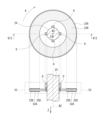
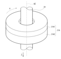
- FIG. 3 is a perspective view illustrating a configuration example of the power transmission device illustrated in FIG. 1 .
- FIG. 4 is an explanatory diagram illustrating a configuration example of the power transmission device illustrated in FIG. 3.
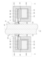
- FIG. 5 is a cross-sectional view illustrating an example of a configuration of the power transmission device illustrated in FIG. 3 .
- FIG. 6 is an explanatory diagram showing an example of the configuration of the stator shown in FIG. FIG.
- FIG. 7 is an explanatory diagram illustrating an example of the configuration of the rotor shown in FIG.
- FIG. 8 is an explanatory diagram illustrating an operation example of the power transmission device illustrated in FIG.
- FIG. 9 is a perspective view illustrating a configuration example of a power transmission device according to a reference example.
- FIG. 10 is an explanatory diagram illustrating a configuration example of the power transmission device illustrated in FIG.
- FIG. 11 is a cross-sectional view illustrating a configuration example of a power transfer device according to a modified example of the first embodiment.
- FIG. 12 is a cross-sectional view illustrating a configuration example of a power transfer device according to another modified example of the first embodiment.
- FIG. 13 is a cross-sectional view showing an example of the configuration of the rotor shown in FIG. FIG.
- FIG. 14 is a cross-sectional view illustrating a configuration example of a rotor according to another modified example of the first embodiment.
- FIG. 15 is a diagram illustrating a configuration example of a power transfer device according to another modified example of the first embodiment.
- FIG. 16 is a cross-sectional view illustrating a configuration example of a power transmission device according to another modification of the first embodiment.
- FIG. 17 is a block diagram showing an example of the configuration of a motor device according to the second embodiment.
- FIG. 18 is a perspective view illustrating a configuration example of the power transmission device illustrated in FIG. 17.
- FIG. 19 is an explanatory diagram illustrating a configuration example of the power transmission device illustrated in FIG.
- FIG. 20 is a cross-sectional view illustrating an example of a configuration of the power transmission device illustrated in FIG.
- FIG. 21 is an explanatory diagram illustrating one configuration example of the rotor shown in FIG.
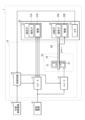
- First Embodiment [Configuration example] 1 shows an example of a configuration of a motor device 1 including a power transmission device according to a first embodiment of the present invention.
- the motor device 1 is connected to an external control device 8 and a DC power source 9.
- the external control device 8 is configured to instruct the motor device 1 on a rotation speed.
- the DC power source 9 is configured to supply DC power to the motor device 1.
- the motor device 1 is configured to generate a driving force, which is mechanical energy, based on an instruction from the external control device 8, using the DC power supplied from the DC power source 9.
- the motor device 1 includes a drive unit 10 and a motor 30.
- the drive unit 10 is configured to drive the motor 30.
- the drive unit 10 has inverters 11 and 12, a power transmission device 20, and a control circuit 19.
- the inverter 11 is configured to convert the DC power supplied from the DC power source 9 into three-phase (U-phase, V-phase, W-phase) AC power based on instructions from the control circuit 19. The inverter 11 then supplies this three-phase AC power to the windings 31B (described below) of the stator 31 of the motor 30.
- the inverter 12 is configured to convert the DC power supplied from the DC power source 9 into single-phase AC power based on instructions from the control circuit 19. The inverter 12 then supplies this AC power to a winding 21B (described below) of a stator 21 of the power transmission device 20.
- the power transmission device 20 has a stator 21, a rotor 22, a rectifying member 23, and a shaft 24.
- the power transmission device 20 is configured to transmit AC power supplied from the inverter 12 from the stator 21 to the rotor 22 by non-contact transmission.
- FIG. 2 shows an example of the configuration of the inverter 12 and the power transmission device 20. Note that FIG. 2 also shows the DC power supply 9 and the winding 32B of the rotor 32 of the motor 30.
- the inverter 12 is connected to the DC power supply 9 via the voltage line L11 and the reference voltage line L12.
- the inverter 12 is a full-bridge type circuit.
- the inverter 12 has switching elements SW1 to SW4 and a switching control circuit 18.
- Each of the switching elements SW1 to SW4 is configured using, for example, a field effect transistor or an insulated gate bipolar transistor.
- the switching element SW1 is provided on a path connecting the voltage line L11 and the node N1, and is configured to perform a switching operation based on a control signal supplied from the switching control circuit 18.
- the switching element SW2 is provided on a path connecting the node N1 and the reference voltage line L12, and is configured to perform a switching operation based on a control signal supplied from the switching control circuit 18.
- the switching element SW3 is provided on a path connecting the voltage line L11 and the node N2, and is configured to perform a switching operation based on a control signal supplied from the switching control circuit 18.
- the switching element SW4 is provided on a path connecting the node N2 and the reference voltage line L12, and is configured to perform a switching operation based on a control signal supplied from the switching control circuit 18.
- the switching control circuit 18 is configured to control the switching operation of the switching elements SW1 to SW4 by supplying control signals to the switching elements SW1 to SW4, respectively, based on instructions from the control circuit 19.
- the power transmission device 20 has a winding 21B, a winding 22B, and a rectifier circuit 22C.
- the winding 21B is provided on the stator 21, one end of the winding 21B is connected to a node N1 of the inverter 12, and the other end of the winding 21B is connected to a node N2 of the inverter 12.
- the winding 22B is provided on the rotor 22, one end of the winding 22B is connected to a node N3 of the rectifier circuit 22C, and the other end is connected to a node N4 of the rectifier circuit 22C.
- the windings 21B and 22B form a so-called rotary transformer, and the winding 22B is adapted to receive AC power supplied from the winding 21B.
- the rectifier circuit 22C is provided on the rotor 22, and is configured to rectify the AC power supplied from the winding 22B of the rotor 22.
- the rectifier circuit 22C has diodes D1 to D4.
- the diodes D1 to D4 are rectifier elements.
- the cathode of diode D1 is connected to voltage line L21, and the anode is connected to node N3.
- the cathode of diode D2 is connected to node N3, and the anode is connected to reference voltage line L22.
- the cathode of diode D3 is connected to voltage line L21, and the anode is connected to node N4.
- the cathode of diode D4 is connected to node N4, and the anode is connected to reference voltage line L22.
- Voltage line L21 and reference voltage line L22 are connected to winding 32B (described below) of rotor 32 of motor 30.
- the inverter 12 converts the DC power supplied from the DC power source 9 into AC power.
- the power transmission device 20 transmits the AC power supplied from the inverter 12 from the stator 21 of the power transmission device 20 to the rotor 22 of the power transmission device 20, and rectifies the transmitted AC power.
- the power transmission device 20 supplies the rectified power to the winding 32B (described later) of the rotor 32 of the motor 30.
- the power rectified by the rectifier circuit 22C is directly supplied to the winding 32B, but this is not limited to this. Instead, for example, the power rectified by the rectifier circuit 22C may be supplied to the winding 32B via a stabilizing circuit including a capacitor.
- Figures 3 and 4 show an example of the configuration of the power transmission device 20.
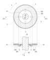
- Figure 5 shows an example of the cross-sectional structure of the power transmission device 20 in a plane including the rotation axis AZ.
- Figure 6 shows an example of the configuration of the stator 21.
- Figure 6 also shows the cross-sectional structure of the stator 21 in a plane including the rotation axis AZ in the direction of the VI-VI arrows.
- Figure 7 shows an example of the configuration of the rotor 22.
- Figure 7 also shows the cross-sectional structure of the rotor 22 in a plane including the rotation axis AZ in the direction of the VII-VII arrows.
- the stator 21 is a so-called stator, and is fixed to a housing (not shown) of the motor device 1. As shown in Figures 3 to 6, the stator 21 has a magnetic core 21A and windings 21B.
- the magnetic core 21A is made of a magnetic material such as ferrite.
- the magnetic core 21A includes magnetic cores 21A1 and 21A2.
- the magnetic cores 21A1 and 21A2 are arranged to sandwich the rotor 22 in the Z direction.
- the Z direction is the extension direction of the rotation axis AZ, and is the direction from the motor 30 to the power transmission device 20 as shown in FIG. 1.
- Each of the magnetic cores 21A1 and 21A2 is a ring-shaped magnetic member having a through hole 120 (FIGS. 5 and 6) through which the shaft 24 passes.
- the outer part of the magnetic core 21A1 in the radial direction (horizontal direction in FIG. 5) is bent in the Z direction and is connected to the magnetic core 21A2 at the connecting portion 125.
- the outer part of the magnetic core 21A2 in the radial direction (horizontal direction in FIG. 5) is bent in the opposite direction to the Z direction and is connected to the magnetic core 21A1 at the connecting portion 125.
- the inner part of the magnetic core 21A2 in the radial direction (horizontal direction in FIG. 5) is bent in the opposite direction to the Z direction.
- the magnetic core 21A2 has a groove-shaped recess along the circumferential direction A (FIG. 6) of the rotation axis AZ on the surface facing the rotor 22, and the winding 21B is provided in this recess.
- the magnetic core 21A having the magnetic cores 21A1 and 21A2 has a cavity 122 along the circumferential direction A, and an opening 123 (FIGS. 5 and 6) that connects the through hole 120 through which the shaft 24 passes and this cavity 122.
- a gap G (FIG. 5) is provided between the magnetic cores 21A1 and 21A2.
- Winding 21B is wound multiple times along the recess of magnetic core 21A2.
- winding 21B is wound around bobbin 21C, and bobbin 21C around which winding 21B is wound is fitted into the recess of magnetic core 21A2.
- Winding 21B is connected to inverter 12, for example, via a hole (not shown) provided in magnetic core 21A2.
- the rotor 22 is configured to rotate around a rotation axis AZ.
- the rotor 22 is arranged so as to be sandwiched between the magnetic cores 21A1 and 21A2 of the stator 21 in the Z direction, and is fixed to the shaft 24.
- the rotor 22 has a substrate 22A, a winding 22B, and four diodes D (diodes D1 to D4).
- the substrate 22A is, for example, a printed circuit board (PCB).
- the substrate 22A is connected to the shaft 24, and rotates in the circumferential direction A around the rotation axis AZ in response to the rotation of the shaft 24.
- the substrate 22A is provided with a pattern wiring of the winding 22B.
- the substrate 22A has four diodes D (diodes D1 to D4 shown in Figure 2) mounted thereon, and is provided with a pattern wiring of a rectifier circuit 22C ( Figure 2) including these four diodes D.
- the winding 22B is configured using a pattern wiring provided on the substrate 22A, and is wound multiple times along the circumferential direction A (FIG. 7) of the rotation axis AZ.
- the winding 22B is configured using a metal material such as copper.
- the winding 22B is provided on both sides of the substrate 22A.
- the winding 22B may be provided on one of the two sides of the substrate 22A.
- the winding 22B may be configured using a pattern wiring inside the substrate 22A.
- One end and the other end of the winding 22B are connected to a rectifier circuit 22C (FIG. 2) including four diodes D.
- the four diodes D are mounted at four positions surrounding the shaft 24 so as to be in contact with the shaft 24.
- the four diodes D are mounted on the surface of the substrate 22A facing away from the Z direction.
- each of the four diodes D is mounted on the substrate 22A by so-called through-hole mounting.
- the four diodes D may also be mounted on the substrate surface of the substrate 22A by so-called surface mounting.
- the magnetic cores 21A1 and 21A2 are magnetically coupled to each other via the gap G near the opening 123.
- the power transmission device 20 converts the AC power supplied from the inverter 12 at the ratio of the number of turns of the winding 21B to the number of turns of the winding 22B, and supplies the converted AC power to the rectifier circuit 22C including four diodes D.
- the rectifier circuit 22C then rectifies the AC power supplied from the winding 22B of the rotor 22, and supplies the rectified power to the winding 32B (described below) of the rotor 32 of the motor 30.
- the shaft 24 ( Figure 1) is connected to the rotor 32 of the motor 30 and is configured to rotate about the rotation axis AZ in response to the driving force generated by the motor 30.
- the control circuit 19 is configured to control the operation of the inverters 11, 12 based on instructions from the external control device 8 and a control signal indicating the rotation speed supplied from the motor 30. Specifically, the control circuit 19 controls the operation of the inverter 11 based on instructions from the external control device 8 and a control signal indicating the rotation speed of the motor 30, thereby controlling the rotation speed of the motor 30. The control circuit 19 also controls the strength of the magnetic field generated by the rotor 32 of the motor 30 by controlling the operation of the inverter 12 based on the control signal indicating the rotation speed supplied from the motor 30.
- control circuit 19 is configured to strengthen the magnetic field generated by the rotor 32 of the motor 30 when the rotation speed of the motor 30 is slow, and to weaken the magnetic field generated by the rotor 32 of the motor 30 when the rotation speed of the motor 30 is fast.
- the motor 30 is a wound field type synchronous motor.
- the motor 30 has a stator 31, a rotor 32, and a sensor 33.
- the stator 31 is a so-called stator, and is fixed to a housing (not shown) of the motor 30.
- the stator 31 has a magnetic core 31A and a winding 31B.
- the winding 31B is supplied with three-phase (U-phase, V-phase, W-phase) AC power generated by the inverter 11.
- the rotor 32 is a so-called rotor, and is configured to rotate the rotation axis AZ.
- the rotor 32 has a magnetic core 32A and a winding 32B.
- a signal rectified by the rectifier circuit 22C is supplied to the winding 32B.
- the sensor 33 is configured to detect the rotation speed of the rotor 32.
- the sensor 33 is configured to provide a control signal indicative of the rotation speed of the rotor 32 to the control circuit 19.
- the motor device 1 controls the rotation speed of the motor 30 based on the three-phase (U-phase, V-phase, W-phase) AC power generated by the inverter 11, and controls the magnetic field generated by the rotor 32 of the motor 30 based on the single-phase AC power generated by the inverter 12. For example, when the rotation speed of the motor 30 is slow, the motor device 1 strengthens the magnetic field generated by the rotor 32 of the motor 30, and when the rotation speed of the motor 30 is fast, the magnetic field generated by the rotor 32 of the motor 30 is weakened. This makes it possible for the motor device 1 to increase the efficiency of the motor 30 over a wide range of rotation speeds.
- the shaft 24 corresponds to a specific example of a "shaft” in an embodiment of the present disclosure.
- the rotation axis AZ corresponds to a specific example of a "rotation axis” in an embodiment of the present disclosure.
- the magnetic core 21A corresponds to a specific example of a “magnetic core” in an embodiment of the present disclosure.
- the cavity 122 corresponds to a specific example of a "cavity” in an embodiment of the present disclosure.
- the opening 123 corresponds to a specific example of an "opening” in an embodiment of the present disclosure.
- the winding 21B corresponds to a specific example of a "first winding" in an embodiment of the present disclosure.
- the substrate 22A corresponds to a specific example of a "rotating member" in an embodiment of the present disclosure.
- the winding 22B corresponds to a specific example of a “second winding” in an embodiment of the present disclosure.
- the diodes D1 to D4 correspond to a specific example of "one or more rectifying elements" in an embodiment of the present disclosure.
- the stator 31 corresponds to a specific example of a "motor stator” in an embodiment of the present disclosure.
- the magnetic core 31A corresponds to a specific example of a "first motor magnetic core” in an embodiment of the present disclosure.
- the winding 31B corresponds to a specific example of a "first motor winding” in an embodiment of the present disclosure.
- the rotor 32 corresponds to a specific example of a "motor rotor” in an embodiment of the present disclosure.
- the magnetic core 32A corresponds to a specific example of a "second motor magnetic core” in an embodiment of the present disclosure.
- the winding 32B corresponds to a specific example of a "second motor winding” in an embodiment of the present disclosure.
- the inverter 12 corresponds to a specific example of an "inverter” in an embodiment of the present disclosure.
- the rectifier circuit 22C corresponds to a specific example of a "rectifier circuit” in an embodiment of the present disclosure.
- the control circuit 19 controls the operation of the inverters 11 and 12 based on instructions from the external control device 8 and a control signal indicating the rotation speed supplied from the motor 30.
- the inverter 11 converts the DC power supplied from the DC power source 9 into three-phase (U-phase, V-phase, W-phase) AC power based on instructions from the control circuit 19, and supplies the three-phase AC power to the winding 31B of the stator 31 of the motor 30.
- the inverter 12 converts the DC power supplied from the DC power source 9 into single-phase AC power based on instructions from the control circuit 19, and supplies the AC power to the winding 21B of the stator 21 of the power transmission device 20.
- the power transmission device 20 transmits the AC power supplied from the inverter 12 from the stator 21 to the rotor 22 by non-contact transmission, and rectifies the transmitted AC power.
- the power transmission device 20 then supplies the rectified power to the winding 32B of the rotor 32 of the motor 30.
- the motor 30 generates a driving force, which is mechanical energy, based on the three-phase (U-phase, V-phase, W-phase) AC power supplied from the inverter 11. This causes the shaft 24 to rotate about the rotation axis AZ.
- the sensor 33 of the motor 30 supplies a control signal indicating the rotation speed of the motor 30 to the control circuit 19.
- AC power is supplied from the inverter 12 to the windings 21B of the stator 21 of the power transmission device 20.
- the rotor 22 rotates around the rotation axis AZ in, for example, the circumferential direction A shown in FIG. 3.
- FIG. 8 shows a cross-sectional view of the power transmission device 20.
- the winding 21B of the stator 21 generates a magnetic field based on the AC power supplied from the inverter 12. Near the opening 123, the magnetic cores 21A1 and 21A2 are magnetically coupled to each other through the gap G of the opening 123. In this way, in the power transmission device 20, a magnetic path MP is generated inside the magnetic cores 21A1 and 21A2.
- the winding 22B of the rotor 22 generates AC power based on the magnetic field in this magnetic path MP, and supplies the generated AC power to the rectifier circuit 22C including four diodes D.
- power is transmitted by non-contact transmission, which can improve reliability compared to the case where power is transmitted by contact transmission using, for example, a slip ring and a brush.
- the rectifier circuit 22C rectifies the AC voltage supplied from the winding 22B of the rotor 22.
- the four diodes D of the rectifier circuit 22C are mounted so as to be in contact with the shaft 24.
- the heat generated in the four diodes D is transmitted over a wide area via the shaft 24 and dissipated.
- the power transmission device 20 can effectively dissipate heat from the four diodes D, reducing the possibility of the power transmission device 20 malfunctioning or breaking down, and improving reliability.
- the centrifugal force acting on the four diodes D when the shaft 24 rotates around the rotation axis AZ can be reduced.
- the stress acting on the four diodes D and the solder between the four diodes D and the substrate 22A can be reduced, improving reliability.
- the four diodes D are mounted on the substrate 22A of the rotor 22.
- the substrate 23A is, for example, a printed circuit board, and is connected to the shaft 24, and rotates in the circumferential direction A around the rotation axis AZ in response to the rotation of the shaft 24.
- Four diodes D are mounted on the substrate 23A, and pattern wiring of the rectifier circuit 22C ( Figure 2) including these four diodes D is provided.
- the four diodes D are mounted on the substrate 23A separate from the substrate 22A, which increases the size.
- the power transmission device 20 it is not necessary to provide the substrate 23A, and the four diodes D can be accommodated between the magnetic core 21A1 and the shaft 24, so the size of the power transmission device 20 can be reduced. 5 and 7, the four diodes D are surrounded by the magnetic core 21A. Therefore, noise radiation from the vicinity of the four diodes D caused by switching operations is shielded to some extent by the magnetic core 21A. As a result, the power transmission device 20 can suppress noise radiation.
- the rectifier circuit 22C supplies the rectified power to the windings 32B of the rotor 32 of the motor 30.
- a magnetic field is generated in the rotor 32 of the motor 30.
- the control circuit 19 strengthens the magnetic field generated by the rotor 32 of the motor 30, and when the rotation speed of the motor 30 is fast, the control circuit 19 weakens the magnetic field generated by the rotor 32 of the motor 30.
- the motor device 1 can increase the efficiency of the motor 30 over a wide range of rotation speeds.
- the power transmission device 20 includes a magnetic core 21A having a ring shape including a through hole 120 through which the shaft 24 passes, containing a cavity 122 therein along the circumferential direction of the rotation axis AZ of the shaft 24, and having an opening 123 arranged along the circumferential direction A on the surface in contact with the through hole 120 and connecting the through hole 120 and the cavity 122, a first winding (winding 21B) arranged in the cavity 122 and wound along the circumferential direction A, a rotating member (substrate 22A) arranged at a position corresponding to the opening 123 in the axial direction of the rotation axis AZ and rotatable in the circumferential direction A inside the cavity 122 in response to the rotation of the shaft 24, a second winding (winding 22B) arranged on the rotating member (substrate 22A) and wound along the circumferential direction A, and four diodes D arranged on the rotating member (substrate 22A) and connected to the second winding (wind
- the four diodes D are provided in contact with the shaft 24.
- the heat generated in the four diodes D is transferred and dissipated over a wide area via the shaft 24, so that the four diodes D can be effectively dissipated.
- the stress applied to the four diodes D when the shaft 24 rotates around the rotation axis AZ can be reduced. As a result, the reliability of the power transmission device 20 can be improved.
- the four diodes are in contact with the shaft 24. This allows the four diodes to dissipate heat effectively and reduces the stress on the four diodes and the solder joints of the four diodes, thereby improving reliability.
- the four diodes D are provided on the surface of the substrate 22A facing the Z direction as shown in Figs. 4 and 5, but the present invention is not limited to this. Instead of this, the four diodes D may be provided on the surface of the substrate 22A facing the Z direction as shown in Fig. 11. Also, as shown in Figs. 12 and 13, a cutout may be provided in a part of the substrate 22A, and the four diodes D may be provided in this cutout.
- the substrate 22A has four cutouts 22D at four positions surrounding the shaft 24. The four diodes D are provided in each of the four cutouts 22D and mounted so as to be in contact with the shaft 24.
- the four diodes D are individually mounted as shown in Fig. 7, but the present invention is not limited to this. Instead of this, for example, when a rectifier circuit 22C including four diodes D is housed in one package, the rectifier circuit 22C may be mounted so as to be in contact with the shaft 24 as shown in Fig. 14.
- the four diodes D are mounted in contact with the shaft 24 to effectively dissipate heat from the four diodes D.
- a cooling medium such as oil may be caused to flow inside the shaft 24.
- a flow path 24A for flowing a cooling medium such as oil is provided inside the shaft 24.
- the magnetic core 21A is provided with the opening 123, but this is not limited thereto, and instead, as shown in FIG. 16, for example, other openings may be provided.
- the magnetic core 21A1 has a plate shape.
- the magnetic core 21A having the magnetic core 21A1 and the magnetic core 21A2 is provided with an opening 124 that connects the space outside the magnetic core 21A in the radial direction of the rotation axis AZ (horizontal direction in FIG. 16) with the cavity 122.
- a gap G is provided between the magnetic core 21A1 and the magnetic core 21A2.
- the magnetic core 21A1 and the magnetic core 21A2 are magnetically coupled to each other through the gap G at the opening 123, and are also magnetically coupled to each other through the gap G at the opening 124.
- FIG. 17 shows an example of the configuration of the motor device 2.
- the motor device 2 includes a drive unit 40 and a motor 30.
- the drive unit 40 includes a power transmission device 50.
- the power transmission device 50 includes a stator 21, a rotor 52, and a shaft 24.
- FIGS. 18 and 19 show an example of the configuration of the power transmission device 50.
- FIG. 20 shows an example of the cross-sectional structure of the power transmission device 50 in a plane including the rotation axis AZ.
- FIG. 21 shows an example of the configuration of the rotor 52.
- the rotor 52 has a substrate 52A, a winding 22B, and four diodes D (diodes D1 to D4).
- the substrate 52A is, for example, a printed circuit board.
- the substrate 52A is connected to the shaft 24, and rotates in the circumferential direction A around the rotation axis AZ in response to the rotation of the shaft 24.
- the substrate 52A is provided with the windings 22B as in the first embodiment.
- the windings 22B are provided on the surface of the substrate 52A that faces away from the Z direction.
- the substrate 52A also has four diodes D (diodes D1 to D4 shown in FIG. 2) mounted thereon, and pattern wiring in a rectifier circuit 22C (FIG. 2) that includes these four diodes D is provided.
- the four diodes D are mounted at four positions surrounding the shaft 24 so as to be spaced apart from the shaft 24.
- the four diodes D are mounted on the Z-direction surface of the substrate 22A. Note that this is not limited to this, and for example, the diodes may be mounted on the surface of the substrate 22A in the direction opposite to the Z direction.
- each of the four diodes D is mounted on the substrate 52A by so-called through-hole mounting. Note that this is not limited to this, and the four diodes D may be mounted on the substrate surface of the substrate 52A by so-called surface mounting.
- the four diodes D are mounted on the substrate 52A of the rotor 22.
- the size of the power transmission device 50 can be made smaller than when the four diodes D are mounted on a substrate 23A separate from the substrate 52A, for example, as shown in Figures 9 and 10.
- some of the four diodes D are provided in the cavity 122, and the four diodes D are surrounded by the magnetic core 21A. Note that this is not limited to the above, and for example, all of the four diodes D may be provided in the cavity 122. This allows noise radiation from the vicinity of the four diodes D caused by switching operations to be shielded to some extent by the magnetic core 21A. As a result, the power transmission device 50 can suppress noise radiation.
- the first surface (surface in the direction opposite to the Z direction) of the rotating member (substrate 52A) faces the first inner surface (surface in the direction opposite to the Z direction) that contacts the cavity 122 of the magnetic core 21A (surface in the direction opposite to the Z direction) and the second surface (surface in the direction opposite to the first surface) of the rotating member (substrate 52A) faces the second inner surface (surface in the direction opposite to the Z direction) that contacts the cavity 122 of the magnetic core 21A (surface in the direction opposite to the Z direction).
- the distance between the second surface of the rotating member (substrate 52A) and the second inner surface of the magnetic core 21A is longer than the distance between the first surface of the rotating member (substrate 52A) and the first inner surface of the magnetic core 21A, and the four diodes D are provided on the second surface of the rotating member (substrate 52A).
- the four diodes D can be placed away from the magnetic core 21A, reducing the possibility of the inductance component becoming large.
- the four diodes D were provided on the surface of the substrate 52A facing in the opposite direction to the Z direction, the diodes D would be placed near the magnetic core 21A1, which could increase the inductance component of the diodes D.
- the four diodes D are provided on the surface of the substrate 52A facing in the Z direction, reducing the possibility of the inductance component of the diodes D becoming large.
- some of the four diodes are provided in the cavity, so that noise radiation from the vicinity of the four diodes is shielded to some extent by the magnetic core, making it possible to suppress noise radiation.
- the first surface of the rotating member faces the first inner surface that contacts the cavity of the magnetic core
- the second surface of the rotating member faces the second inner surface that contacts the cavity of the magnetic core.
- the distance between the second surface of the rotating member and the second inner surface of the magnetic core is longer than the distance between the first surface of the rotating member and the first inner surface of the magnetic core, and the four diodes are provided on the second surface of the rotating member. This reduces the possibility that the inductance component of the diodes will become large.
- the magnetic core 21A is provided with an opening 123, but this is not limited to this, and instead, the magnetic core 21A may have further openings, for example as in the case of variant example 1-4 of the first embodiment (FIG. 16).
- four diodes D are provided in the rectifier circuit 22C, but this is not limited to the above.
- four switching elements may be provided as rectifier elements in the rectifier circuit 22C, and the four switching elements in the rectifier circuit 22C may be operated in synchronization with the switching operation of the four switching elements SW1 to SW4 in the inverter 12.
- the circuit configuration of the rectifier circuit 23B shown in each of the above embodiments is merely an example, and is not limited to the disclosed circuit configuration.
- the rectifier circuit may have one diode or multiple diodes.
- stator 21 and rotors 22, 52 shown in the above embodiments are merely examples and are not limited to the shapes disclosed.
- circuit configurations of the inverter 12 and the rectifier circuit 22C shown in the above embodiments are merely examples and are not limited to the disclosed circuit configurations.
- a magnetic core having a ring shape including a through hole through which a shaft passes, including a cavity along a circumferential direction of a rotation axis of the shaft, and an opening provided along the circumferential direction on a surface in contact with the through hole and connecting the through hole and the cavity; a first winding provided in the cavity and wound along the circumferential direction; a rotating member provided at a position corresponding to the opening in the axial direction of the rotating shaft, the rotating member being rotatable in the circumferential direction within the cavity in response to rotation of the shaft; a second winding provided on the rotating member and wound in the circumferential direction; one or more rectifying elements provided on the rotating member and connected to the second winding.
- a motor having a motor stator including a first motor magnetic core and a first motor winding, and a motor rotor including a second motor magnetic core and a second motor winding; a shaft connected to the motor rotor; An inverter; a magnetic core having a ring shape including a through hole through which the shaft passes, including a cavity along a circumferential direction of the shaft, and an opening provided along the circumferential direction on a surface in contact with the through hole and connecting the through hole and the cavity; a first winding connected to the inverter, provided in the cavity, and wound in the circumferential direction; a rotating member provided at a position corresponding to the opening in the axial direction of the shaft, the rotating member being rotatable in the circumferential direction within the cavity in response to rotation of the shaft; a second winding provided on the rotating member and wound in the circumferential direction; a motor device comprising: one or more rectifying elements provided on the rotating member and connected to the second winding.
Landscapes
- Engineering & Computer Science (AREA)
- Power Engineering (AREA)
- Synchronous Machinery (AREA)
Abstract
Description
本発明は、非接触で電力を伝送する電力伝送デバイス、およびそのような電力伝送デバイスが設けられたモータ装置に関する。 The present invention relates to a power transmission device that transmits power contactlessly, and a motor device equipped with such a power transmission device.
例えば、モータには、巻線界磁式の同期モータ(EESM:Electrically Excited Synchronous Motor)がある。このモータは、巻線が巻き付けられた固定子と、巻線が巻き付けられた回転子とを有する。このモータでは、モータの回転速度に応じて、回転子に巻き付けられた巻線に流す電流を変化させることにより、モータの効率の向上を図ることができる。 For example, one type of motor is the electrically excited synchronous motor (EESM). This motor has a stator with windings wound around it, and a rotor with windings wound around it. With this type of motor, the efficiency of the motor can be improved by changing the current flowing through the windings wound around the rotor according to the rotational speed of the motor.
ところで、固定子と回転子との間で電力を伝送可能なデバイスがある。例えば、特許文献1には、巻線が巻き付けられた固定子と、巻線が巻き付けられた回転子とを備え、固定子と回転子との間で電力を伝送可能な回転トランスが開示されている。
By the way, there are devices that can transmit power between a stator and a rotor. For example,
電子デバイスでは、サイズが小さいことが望まれており、固定子から回転子に電力を伝送可能な電力伝送デバイスにおいても、サイズが小さいことが期待される。 Small size is desirable for electronic devices, and small size is also expected for power transmission devices capable of transmitting power from a stator to a rotor.
サイズを小さくすることができる電力伝送デバイスおよびモータ装置を提供することが望ましい。 It is desirable to provide a power transmission device and a motor apparatus that can be reduced in size.
本発明の一実施の形態に係る電力伝送デバイスは、磁気コアと、第1の巻線と、回転部材と、第2の巻線と、1以上の整流素子とを備えている。磁気コアは、シャフトが貫く貫通穴を含むリング形状を有し、シャフトにおける回転軸の周方向に沿った空洞を内部に含み、貫通穴と接する面において周方向に沿って設けられ貫通穴と空洞とをつなぐ開口部を有するものである。第1の巻線は、空洞に設けられ、周方向に沿って巻かれたものである。回転部材は、回転軸の軸方向における開口部に対応する位置に設けられ、シャフトの回転に応じて、空洞の内部において周方向に回動可能なものである。第2の巻線は、回転部材に設けられ、周方向に沿って巻かれたものである。1以上の整流素子は、回転部材に設けられ、第2の巻線に接続されたものである。 The power transmission device according to one embodiment of the present invention includes a magnetic core, a first winding, a rotating member, a second winding, and one or more rectifying elements. The magnetic core has a ring shape including a through hole through which the shaft passes, includes a cavity inside along the circumferential direction of the rotating axis of the shaft, and has an opening along the circumferential direction on a surface in contact with the through hole, connecting the through hole and the cavity. The first winding is provided in the cavity and wound along the circumferential direction. The rotating member is provided at a position corresponding to the opening in the axial direction of the rotating shaft, and is capable of rotating circumferentially inside the cavity in response to rotation of the shaft. The second winding is provided on the rotating member and wound along the circumferential direction. One or more rectifying elements are provided on the rotating member and connected to the second winding.
本発明の一実施の形態に係るモータ装置は、モータと、シャフトと、インバータと、磁気コアと、第1の巻線と、回転部材と、第2の巻線と、1以上の整流素子とを備えている。モータは、第1のモータ磁気コアと第1のモータ巻線とを含むモータ固定子と、第2のモータ磁気コアと第2のモータ巻線とを含むモータ回転子とを有するものである。シャフトは、モータ回転子に接続されたものである。磁気コアは、シャフトが貫く貫通穴を含むリング形状を有し、シャフトの周方向に沿った空洞を内部に含み、貫通穴と接する面において周方向に沿って設けられ貫通穴と空洞とをつなぐ開口部を有するものである。第1の巻線は、インバータに接続され、空洞に設けられ、周方向に沿って巻かれたものである。回転部材は、シャフトの軸方向における開口部に対応する位置に設けられ、シャフトの回転に応じて、空洞の内部において周方向に回動可能なものである。第2の巻線は、回転部材に設けられ、周方向に沿って巻かれたものである。1以上の整流素子は、回転部材に設けられ、第2の巻線に接続されたものである。 A motor device according to one embodiment of the present invention includes a motor, a shaft, an inverter, a magnetic core, a first winding, a rotating member, a second winding, and one or more rectifying elements. The motor includes a motor stator including a first motor magnetic core and a first motor winding, and a motor rotor including a second motor magnetic core and a second motor winding. The shaft is connected to the motor rotor. The magnetic core has a ring shape including a through hole through which the shaft passes, includes a cavity along the circumferential direction of the shaft, and has an opening provided along the circumferential direction on a surface in contact with the through hole and connecting the through hole and the cavity. The first winding is connected to the inverter, provided in the cavity, and wound along the circumferential direction. The rotating member is provided at a position corresponding to the opening in the axial direction of the shaft, and is capable of rotating circumferentially inside the cavity in response to rotation of the shaft. The second winding is provided on the rotating member and wound along the circumferential direction. One or more rectifying elements are provided on the rotating member and connected to the second winding.
本発明の一実施の形態に係る電力伝送デバイスおよびモータ装置によれば、サイズを小さくすることができる。 The power transmission device and motor device according to one embodiment of the present invention can be made smaller in size.
以下、本発明の実施の形態について、図面を参照して詳細に説明する。なお、説明は以下の順序で行う。
1.第1の実施の形態
2.第2の実施の形態
DETAILED DESCRIPTION OF THE PREFERRED EMBODIMENTS Hereinafter, preferred embodiments of the present invention will be described in detail with reference to the accompanying drawings. The description will be given in the following order.
1.
<第1の実施の形態>
[構成例]
図1は、本発明の第1の実施の形態に係る電力伝送デバイスを備えたモータ装置1の一構成例を表すものである。モータ装置1は、外部制御装置8および直流電源9に接続される。外部制御装置8は、モータ装置1に対して、回転速度を指示するように構成される。直流電源9は、モータ装置1に対して直流電力を供給するように構成される。モータ装置1は、直流電源9から供給された直流電力を用いて、外部制御装置8からの指示に基づいて、機械的エネルギである駆動力を生成するように構成される。モータ装置1は、駆動部10と、モータ30とを備えている。
First Embodiment
[Configuration example]
1 shows an example of a configuration of a
駆動部10は、モータ30を駆動するように構成される。駆動部10は、インバータ11,12と、電力伝送デバイス20と、制御回路19とを有している。
The
インバータ11は、制御回路19からの指示に基づいて、直流電源9から供給された直流電力を3相(U相、V相、W相)の交流電力に変換するように構成される。そして、インバータ11は、この3相の交流電力を、モータ30の固定子31の巻線31B(後述)に供給するようになっている。
The
インバータ12は、制御回路19からの指示に基づいて、直流電源9から供給された直流電力を単相の交流電力に変換するように構成される。そして、インバータ12は、この交流電力を、電力伝送デバイス20の固定子21の巻線21B(後述)に供給するようになっている。
The
電力伝送デバイス20は、固定子21と、回転子22と、整流部材23と、シャフト24とを有している。電力伝送デバイス20は、非接触伝送により、インバータ12から供給された交流電力を固定子21から回転子22に伝送するように構成される。
The
図2は、インバータ12および電力伝送デバイス20の一構成例を表すものである。なお、図2には、直流電源9およびモータ30の回転子32の巻線32Bをも図示している。インバータ12は、電圧線L11および基準電圧線L12を介して直流電源9に接続される。
FIG. 2 shows an example of the configuration of the
インバータ12は、この例ではフルブリッジ型の回路である。インバータ12は、スイッチング素子SW1~SW4と、スイッチング制御回路18とを有している。スイッチング素子SW1~SW4のそれぞれは、例えば、電界効果トランジスタや絶縁ゲート型バイポーラトランジスタなどを用いて構成される。スイッチング素子SW1は、電圧線L11とノードN1とを結ぶ経路に設けられ、スイッチング制御回路18から供給された制御信号に基づいてスイッチング動作を行うように構成される。スイッチング素子SW2は、ノードN1と基準電圧線L12とを結ぶ経路に設けられ、スイッチング制御回路18から供給された制御信号に基づいてスイッチング動作を行うように構成される。スイッチング素子SW3は、電圧線L11とノードN2とを結ぶ経路に設けられ、スイッチング制御回路18から供給された制御信号に基づいてスイッチング動作を行うように構成される。スイッチング素子SW4は、ノードN2と基準電圧線L12とを結ぶ経路に設けられ、スイッチング制御回路18から供給された制御信号に基づいてスイッチング動作を行うように構成される。スイッチング制御回路18は、制御回路19からの指示に基づいて、スイッチング素子SW1~SW4に制御信号をそれぞれ供給することにより、スイッチング素子SW1~SW4のスイッチング動作を制御するように構成される。
In this example, the
電力伝送デバイス20は、巻線21Bと、巻線22Bと、整流回路22Cとを有している。巻線21Bは、固定子21に設けられ、巻線21Bの一端はインバータ12のノードN1に接続され、巻線21Bの他端はインバータ12のノードN2に接続される。巻線22Bは、回転子22に設けられ、巻線22Bの一端は整流回路22CのノードN3に接続され、他端は整流回路22CのノードN4に接続される。巻線21B,22Bは、いわゆるロータリートランスを構成し、巻線22Bは、巻線21Bから供給された交流電力を受け取るようになっている。整流回路22Cは、回転子22に設けられ、回転子22の巻線22Bから供給された交流電力を整流するように構成される。整流回路22Cは、ダイオードD1~D4を有している。ダイオードD1~D4は、整流素子である。ダイオードD1のカソードは電圧線L21に接続され、アノードはノードN3に接続される。ダイオードD2のカソードはノードN3に接続され、アノードは基準電圧線L22に接続される。ダイオードD3のカソードは電圧線L21に接続され、アノードはノードN4に接続される。ダイオードD4のカソードはノードN4に接続され、アノードは基準電圧線L22に接続される。電圧線L21および基準電圧線L22は、モータ30の回転子32の巻線32B(後述)に接続される。
The
この構成により、インバータ12は、直流電源9から供給された直流電力を交流電力に変換する。そして、電力伝送デバイス20は、インバータ12から供給された交流電力を、電力伝送デバイス20の固定子21から電力伝送デバイス20の回転子22に伝送し、伝送された交流電力を整流する。そして、電力伝送デバイス20は、整流された電力をモータ30の回転子32の巻線32B(後述)に供給するようになっている。なお、この例では、整流回路22Cにより整流された電力を巻線32Bに直接供給したが、これに限定されるものではなく、これに代えて、例えば、整流回路22Cにより整流された電力を、キャパシタを含む安定化回路を介して、巻線32Bに供給してもよい。
With this configuration, the
図3,4は、電力伝送デバイス20の一構成例を表すものである。図5は、回転軸AZを含む面内での電力伝送デバイス20の断面構造の一例を表すものである。図6は、固定子21の一構成例を表すものである。図6には、VI-VI矢視方向の、回転軸AZを含む面内での固定子21の断面構造をも描いている。図7は、回転子22の一構成例を表すものである。図7には、VII-VII矢視方向の、回転軸AZを含む面内での回転子22の断面構造をも描いている。
Figures 3 and 4 show an example of the configuration of the
固定子21は、いわゆるステータであり、モータ装置1の図示しない筐体に固定される。固定子21は、図3~6に示したように、磁気コア21Aと、巻線21Bとを有している。
The
磁気コア21Aは、例えばフェライトなどの磁性材料を用いて構成される。磁気コア21Aは、磁気コア21A1,21A2を含んでいる。磁気コア21A1,21A2は、Z方向において、回転子22を挟むように設けられる。ここで、Z方向は、回転軸AZの延伸方向であり、図1に示したように、モータ30から電力伝送デバイス20に向かう方向である。磁気コア21A1,21A2のそれぞれは、シャフト24が貫く貫通穴120(図5,6)を有するリング型の磁性部材である。磁気コア21A1の、径方向(図5における横方向)における外側の部分はZ方向に折れ曲がり、連結部125において磁気コア21A2に連結されている。磁気コア21A2の、径方向(図5における横方向)における外側の部分はZ方向とは反対の方向に折れ曲がり、連結部125において磁気コア21A1に連結されている。また、磁気コア21A2の、径方向(図5における横方向)における内側の部分はZ方向とは反対の方向に折れ曲がっている。これにより、磁気コア21A2には、図5に示したように、回転子22と対向する面において、回転軸AZの周方向A(図6)に沿って、溝状の凹部が設けられ、この凹部に巻線21Bが設けられる。この構成により、磁気コア21A1および磁気コア21A2を有する磁気コア21Aには、周方向Aに沿った空洞122が設けられるとともに、シャフト24が貫く貫通穴120とこの空洞122とをつなぐ開口部123(図5,6)が設けられる。この開口部123では、磁気コア21A1と磁気コア21A2との間にギャップG(図5)が設けられる。
The
巻線21Bは、磁気コア21A2の凹部に沿って複数回巻かれている。この例では、巻線21Bは、ボビン21Cに巻かれており、巻線21Bが巻かれたボビン21Cが、磁気コア21A2の凹部にはめ込まれている。巻線21Bは、例えば、磁気コア21A2に設けられた穴(図示せず)を介して、インバータ12に接続される。
回転子22は、回転軸AZを中心として回動するように構成される。回転子22は、Z方向において、固定子21の磁気コア21A1および磁気コア21A2により挟まれるように配置されるとともに、シャフト24に固定される。回転子22は、図5,7に示したように、基板22Aと、巻線22Bと、4つのダイオードD(ダイオードD1~D4)とを有している。
The
基板22Aは、例えばプリント基板(PCB:Printed Circuit Board)である。基板22Aは、シャフト24に接続され、シャフト24の回転に応じて、回転軸AZを中心として周方向Aに回動するようになっている。基板22Aには、巻線22Bのパターン配線が設けられている。また、基板22Aには、4つのダイオードD(図2に示したダイオードD1~D4)が実装されており、これらの4つのダイオードDを含む整流回路22C(図2)のパターン配線が設けられている。
The
巻線22Bは、基板22Aに設けられたパターン配線を用いて構成され、回転軸AZの周方向A(図7)に沿って複数回巻かれている。巻線22Bは、例えば銅などの金属材料を用いて構成される。この例では、巻線22Bは、基板22Aの両面に設けられている。なお、これに限定されるものではなく、巻線22Bは、基板22Aの両面のうちの一方の面に設けられていてもよい。また、基板22Aが多層基板である場合には、巻線22Bは、基板22Aの内部のパターン配線を用いて構成されてもよい。巻線22Bの一端および他端は、4つのダイオードDを含む整流回路22C(図2)に接続される。
The winding 22B is configured using a pattern wiring provided on the
4つのダイオードDは、図7に示したように、シャフト24を囲む4つの位置に、シャフト24に接するように実装される。4つのダイオードDは、基板22Aの、Z方向とは反対の方向の面に実装されている。この例では、4つのダイオードDのそれぞれは、基板22Aに、いわゆるスルーホール実装により実装されている。なお、これに限定されるものではなく、4つのダイオードDは、基板22Aの基板表面に、いわゆる表面実装により実装されてもよい。
As shown in FIG. 7, the four diodes D are mounted at four positions surrounding the
電力伝送デバイス20では、図5に示したように、開口部123付近において、磁気コア21A1および磁気コア21A2が、ギャップGを介して、互いに磁気的に結合される。これにより、電力伝送デバイス20は、インバータ12から供給された交流電力を、巻線21Bの巻数および巻線22Bの巻数の比で変換し、変換された交流電力を、4つのダイオードDを含む整流回路22Cに供給する。そして、整流回路22Cは、回転子22の巻線22Bから供給された交流電力を整流し、整流された電力をモータ30の回転子32の巻線32B(後述)に供給するようになっている。
5, in the
シャフト24(図1)は、モータ30の回転子32に接続され、モータ30が生成した駆動力に応じて、回転軸AZを中心に回転するように構成される。
The shaft 24 (Figure 1) is connected to the
制御回路19は、外部制御装置8からの指示、およびモータ30から供給された回転速度を示す制御信号に基づいて、インバータ11,12の動作を制御するように構成される。具体的には、制御回路19は、外部制御装置8からの指示、およびモータ30における回転速度を示す制御信号に基づいて、インバータ11の動作を制御することにより、モータ30の回転速度を制御する。また、制御回路19は、モータ30から供給された回転速度を示す制御信号に基づいて、インバータ12の動作を制御することにより、モータ30の回転子32が生成する磁界の強さを制御する。具体的には、制御回路19は、例えば、モータ30の回転速度が遅い場合には、モータ30の回転子32が生成する磁界を強くし、モータ30の回転速度が速い場合には、モータ30の回転子32が生成する磁界を弱くするようになっている。
The
モータ30は、巻線界磁式の同期モータである。モータ30は、固定子31と、回転子32と、センサ33とを有している。
The
固定子31は、いわゆるステータであり、モータ30の図示しない筐体に固定される。固定子31は、磁気コア31Aと、巻線31Bとを有している。巻線31Bには、インバータ11により生成された3相(U相、V相、W相)の交流電力が供給されるようになっている。
The
回転子32は、いわゆるロータであり、回転軸AZを回転するように構成される。回転子32は、磁気コア32Aと、巻線32Bとを有している。巻線32Bには、整流回路22Cにより整流された信号が供給されるようになっている。
The
センサ33は、回転子32の回転速度を検出するように構成される。そして、センサ33は、回転子32の回転速度を示す制御信号を制御回路19に供給するようになっている。
The
この構成により、モータ装置1では、インバータ11が生成した3相(U相、V相、W相)の交流電力に基づいて、モータ30の回転速度を制御し、インバータ12が生成した単相の交流電力に基づいて、モータ30の回転子32が生成する磁界を制御する。モータ装置1では、例えば、モータ30の回転速度が遅い場合には、モータ30の回転子32が生成する磁界を強くし、モータ30の回転速度が速い場合には、モータ30の回転子32が生成する磁界を弱くする。これにより、モータ装置1では、幅広い回転速度において、モータ30の効率を高めることが出来るようになっている。
With this configuration, the
ここで、シャフト24は、本開示の一実施の形態における「シャフト」の一具体例に対応する。回転軸AZは、本開示の一実施の形態における「回転軸」の一具体例に対応する。磁気コア21Aは、本開示の一実施の形態における「磁気コア」の一具体例に対応する。空洞122は、本開示の一実施の形態における「空洞」の一具体例に対応する。開口部123は、本開示の一実施の形態における「開口部」の一具体例に対応する。巻線21Bは、本開示の一実施の形態における「第1の巻線」の一具体例に対応する。基板22Aは、本開示の一実施の形態における「回転部材」の一具体例に対応する。巻線22Bは、本開示の一実施の形態における「第2の巻線」の一具体例に対応する。ダイオードD1~D4は、本開示の一実施の形態における「1以上の整流素子」の一具体例に対応する。
Here, the
固定子31は、本開示の一実施の形態における「モータ固定子」の一具体例に対応する。磁気コア31Aは、本開示の一実施の形態における「第1のモータ磁気コア」の一具体例に対応する。巻線31Bは、本開示の一実施の形態における「第1のモータ巻線」の一具体例に対応する。回転子32は、本開示の一実施の形態における「モータ回転子」の一具体例に対応する。磁気コア32Aは、本開示の一実施の形態における「第2のモータ磁気コア」の一具体例に対応する。巻線32Bは、本開示の一実施の形態における「第2のモータ巻線」の一具体例に対応する。インバータ12は、本開示の一実施の形態における「インバータ」の一具体例に対応する。整流回路22Cは、本開示の一実施の形態における「整流回路」の一具体例に対応する。
The
[動作および作用]
続いて、本実施の形態のモータ装置1の動作および作用について説明する。
[Actions and Functions]
Next, the operation and function of the
(全体動作概要)
制御回路19は、外部制御装置8からの指示、およびモータ30から供給された回転速度を示す制御信号に基づいて、インバータ11,12の動作を制御する。インバータ11は、制御回路19からの指示に基づいて、直流電源9から供給された直流電力を3相(U相、V相、W相)の交流電力に変換し、この3相の交流電力を、モータ30の固定子31の巻線31Bに供給する。インバータ12は、制御回路19からの指示に基づいて、直流電源9から供給された直流電力を単相の交流電力に変換し、この交流電力を、電力伝送デバイス20の固定子21の巻線21Bに供給する。電力伝送デバイス20は、非接触伝送により、インバータ12から供給された交流電力を固定子21から回転子22に伝送し、伝送された交流電力を整流する。そして、電力伝送デバイス20は、整流された電力をモータ30の回転子32の巻線32Bに供給する。モータ30は、インバータ11から供給された3相(U相、V相、W相)の交流電力に基づいて、機械的エネルギである駆動力を生成する。これにより、シャフト24が回転軸AZを中心に回転する。モータ30のセンサ33は、モータ30の回転速度を示す制御信号を制御回路19に供給する。
(Overall operation overview)
The
[動作および作用]
続いて、本実施の形態の電力伝送デバイス20の動作および作用について説明する。
[Actions and Functions]
Next, the operation and function of the
電力伝送デバイス20の固定子21の巻線21Bには、インバータ12から交流電力が供給される。回転子22は、回転軸AZを中心に、例えば図3に示した周方向Aに回動する。
AC power is supplied from the
図8は、電力伝送デバイス20の断面図を表すものである。固定子21の巻線21Bは、インバータ12から供給された交流電力に基づいて磁界を発生させる。開口部123付近では、磁気コア21A1および磁気コア21A2は、開口部123のギャップGを介して、互いに磁気的に結合される。このようにして、電力伝送デバイス20では、磁気コア21A1および磁気コア21A2の内部に、磁路MPが生成される。そして、回転子22の巻線22Bは、この磁路MPにおける磁界に基づいて交流電力を生成し、生成した交流電力を4つのダイオードDを含む整流回路22Cに供給する。このように、電力伝送デバイス20では、非接触伝送により電力が伝送されるので、例えばスリップリングおよびブラシを用いて接触伝送により電力を伝送する場合に比べて、信頼性を高めることができる。
FIG. 8 shows a cross-sectional view of the
整流回路22Cは、回転子22の巻線22Bから供給された交流電圧を整流する。整流回路22Cの4つのダイオードDは、シャフト24に接するように実装される。これにより、4つのダイオードDにおいて生じた熱は、シャフト24を介して広い範囲に伝わり、放熱される。これにより、電力伝送デバイス20では、4つのダイオードDを効果的に放熱させることができるので、電力伝送デバイス20が誤動作する可能性や、電力伝送デバイス20が故障する可能性を低減することができ、信頼性を高めることができる。また、このように、4つのダイオードDを、径方向(図5における横方向)におけるシャフト24に近い位置に配置することにより、シャフト24が回転軸AZを中心に回転したときに、4つのダイオードDにかかる遠心力を小さくすることができる。これにより、電力伝送デバイス20では、4つのダイオードDおよび4つのダイオードDと基板22Aとの間のはんだ部にかかる応力(ストレス)を小さくすることができるので、信頼性を高めることができる。
The
また、この電力伝送デバイス20では、4つのダイオードDは、回転子22の基板22Aに実装される。これにより、例えば、図9,10に示す参考例のように、基板22Aとは別の基板23Aに4つのダイオードDを実装する場合に比べて、電力伝送デバイス20のサイズを小さくすることができる。この参考例では、基板23Aは、例えばプリント基板であり、シャフト24に接続され、シャフト24の回転に応じて、回転軸AZを中心として周方向Aに回動する。基板23Aには、4つのダイオードD(図2に示したダイオードD1~D4)が実装されており、これらの4つのダイオードDを含む整流回路22C(図2)のパターン配線が設けられている。この参考例では、基板22Aとは別の基板23Aに4つのダイオードDを実装するので、サイズが大きくなってしまう。一方、本実施の形態に係る電力伝送デバイス20では、基板23Aを設けずに済み、4つのダイオードDを、磁気コア21A1とシャフト24との間に収めることができるので、電力伝送デバイス20のサイズを小さくすることができる。また、図5,7に示したように、4つのダイオードDは、磁気コア21Aにより囲まれる。よって、スイッチング動作に起因する4つのダイオードD付近からのノイズ放射が、磁気コア21Aによりある程度シールドされる。その結果、電力伝送デバイス20では、ノイズ放射を抑制することができる。
In addition, in this
そして、整流回路22Cは、整流された電力をモータ30の回転子32の巻線32Bに供給する。これにより、モータ30の回転子32では、磁界が生成される。制御回路19は、例えば、モータ30の回転速度が遅い場合には、モータ30の回転子32が生成する磁界を強くし、モータ30の回転速度が速い場合には、モータ30の回転子32が生成する磁界を弱くする。これにより、モータ装置1では、幅広い回転速度において、モータ30の効率を高めることが出来る。
Then, the
このように、電力伝送デバイス20では、シャフト24が貫く貫通穴120を含むリング形状を有し、シャフト24における回転軸AZの周方向に沿った空洞122を内部に含み、貫通穴120と接する面において周方向Aに沿って設けられ貫通穴120と空洞122とをつなぐ開口部123を有する磁気コア21Aと、空洞122に設けられ、周方向Aに沿って巻かれた第1の巻線(巻線21B)と、回転軸AZの軸方向における開口部123に対応する位置に設けられ、シャフト24の回転に応じて、空洞122の内部において周方向Aに回動可能な回転部材(基板22A)と、回転部材(基板22A)に設けられ、周方向Aに沿って巻かれた第2の巻線(巻線22B)と、回転部材(基板22A)に設けられ、第2の巻線(巻線22B)に接続された4つのダイオードDとを設けるようにした。これにより、電力伝送デバイス20では、図9,10に示したように基板22Aとは別の基板を設けないで済むので、電力伝送デバイス20のサイズを小さくすることができる。
In this way, the
また、電力伝送デバイス20では、4つのダイオードDをシャフト24に接するように設けた。これにより、4つのダイオードDにおいて生じた熱は、シャフト24を介して広い範囲に伝わり、放熱されるので、4つのダイオードDを効果的に放熱させることができる。また、4つのダイオードDを、径方向(図5における横方向)におけるシャフト24に近い位置に配置することにより、シャフト24が回転軸AZを中心に回転したときに、4つのダイオードDにかかる応力(ストレス)を小さくすることができる。その結果、電力伝送デバイス20では、信頼性を高めることができる
Furthermore, in the
[効果]
以上のように本実施の形態では、シャフトが貫く貫通穴を含むリング形状を有し、シャフトにおける回転軸の周方向に沿った空洞を内部に含み、貫通穴と接する面において周方向に沿って設けられ貫通穴と空洞とをつなぐ開口部を有する磁気コアと、空洞に設けられ、周方向に沿って巻かれた第1の巻線と、回転軸の軸方向における開口部に対応する位置に設けられ、シャフトの回転に応じて、空洞の内部において周方向Aに回動可能な回転部材と、回転部材に設けられ、周方向に沿って巻かれた第2の巻線と、回転部材に設けられ、第2の巻線に接続された4つのダイオードとを設けるようにした。これにより、電力伝送デバイスのサイズを小さくすることができる。
[effect]
As described above, in this embodiment, a magnetic core having a ring shape including a through hole through which the shaft passes, including a cavity along the circumferential direction of the rotating axis of the shaft, and an opening provided along the circumferential direction on a surface in contact with the through hole and connecting the through hole and the cavity, a first winding provided in the cavity and wound along the circumferential direction, a rotating member provided at a position corresponding to the opening in the axial direction of the rotating shaft and capable of rotating in the circumferential direction A inside the cavity in response to the rotation of the shaft, a second winding provided on the rotating member and wound along the circumferential direction, and four diodes provided on the rotating member and connected to the second winding are provided. This makes it possible to reduce the size of the power transmission device.
本実施の形態では、4つのダイオードがシャフト24に接するようにした。これにより、4つのダイオードを効果的に放熱させることができるとともに、4つのダイオードおよび4つのダイオードのはんだ部にかかる応力(ストレス)を小さくすることができるので、信頼性を高めることができる。
In this embodiment, the four diodes are in contact with the
[変形例1-1]
上記実施の形態では、例えば図4,5に示したように、4つのダイオードDを、基板22Aの、Z方向とは反対の方向の面に設けたが、これに限定されるものではない。これに代えて、例えば、図11に示すように、4つのダイオードDを、基板22AのZ方向の面に設けてもよい。また、図12,13に示すように、基板22Aの一部に切り欠き部を設け、4つのダイオードDを、この切り欠き部に設けてもよい。基板22Aは、シャフト24を囲む4つの位置に、4つの切り欠き部22Dを有している。4つのダイオードDは、これらの4つの切り欠き部22Dにそれぞれ設けられ、シャフト24に接するように実装される。
[Modification 1-1]
In the above embodiment, the four diodes D are provided on the surface of the
[変形例1-2]
上記実施の形態では、例えば図7に示したように、4つのダイオードDを、個別に実装したが、これに限定されるものではない。これに代えて、例えば、4つのダイオードDを含む整流回路22Cが1つのパッケージに収められている場合には、図14に示すように、この整流回路22Cを、シャフト24に接するように実装してもよい。
[Modification 1-2]
In the above embodiment, the four diodes D are individually mounted as shown in Fig. 7, but the present invention is not limited to this. Instead of this, for example, when a
[変形例1-3]
上記実施の形態では、4つのダイオードDをシャフト24に接するように実装することにより、4つのダイオードDを効果的に放熱させるようにした。例えば、図15に示すように、このシャフト24の内部に、油などの冷却媒体を流してもよい。この例では、シャフト24の内部に、油などの冷却媒体を流す流路24Aが設けられている。このような流路24Aに冷却媒体を流すことにより、4つのダイオードDをさらに効果的に放熱させることができる。
[Modification 1-3]
In the above embodiment, the four diodes D are mounted in contact with the
[変形例1-4]
上記実施の形態では、図5に示したように、磁気コア21Aは、開口部123を設けるようにしたが、これに限定されるものではなく、これに代えて、例えば図16に示すように、さらに他の開口部を有していてもよい。この例では、磁気コア21A1は板形状を有している。この構成により、磁気コア21A1および磁気コア21A2を有する磁気コア21Aには、回転軸AZの径方向(図16における横方向)における磁気コア21Aの外側の空間と空洞122とをつなぐ開口部124が設けられる。この開口部124では、磁気コア21A1と磁気コア21A2との間にギャップGが設けられる。磁気コア21A1および磁気コア21A2は、開口部123において、ギャップGを介して、互いに磁気的に結合されるとともに、この開口部124において、ギャップGを介して、互いに磁気的に結合される。
[Modification 1-4]
In the above embodiment, as shown in FIG. 5, the
[その他の変形例]
また、これらの変形例のうちの2以上を組み合わせてもよい。
[Other Modifications]
Moreover, two or more of these modifications may be combined.
<2.第2の実施の形態>
次に、第2の実施の形態に係るモータ装置2について説明する。本実施の形態は、上記第1の実施の形態に係る電力伝送デバイス20において、4つのダイオードDの位置を変更したものである。なお、上記第1の実施の形態に係るモータ装置1と実質的に同一の構成部分には同一の符号を付し、適宜説明を省略する。
2. Second embodiment
Next, a
図17は、モータ装置2の一構成例を表すものである。モータ装置2は、駆動部40と、モータ30とを備えている。駆動部40は、電力伝送デバイス50を有している。電力伝送デバイス50は、固定子21と、回転子52と、シャフト24とを有している。
FIG. 17 shows an example of the configuration of the
図18,19は、電力伝送デバイス50の一構成例を表すものである。図20は、回転軸AZを含む面内での電力伝送デバイス50の断面構造の一例を表すものである。図21は、回転子52の一構成例を表すものである。
FIGS. 18 and 19 show an example of the configuration of the
回転子52は、図20,21に示したように、基板52Aと、巻線22Bと、4つのダイオードD(ダイオードD1~D4)とを有している。
As shown in Figures 20 and 21, the
基板52Aは、例えばプリント基板である。基板52Aは、シャフト24に接続され、シャフト24の回転に応じて、回転軸AZを中心として周方向Aに回動するようになっている。この基板52Aには、上記第1の実施の形態の場合と同様に、巻線22Bが設けられている。この例では、巻線22Bは、基板52Aの、Z方向とは反対の方向の面に設けられている。また、基板52Aには、4つのダイオードD(図2に示したダイオードD1~D4)が実装されており、これらの4つのダイオードDを含む整流回路22C(図2)におけるパターン配線が設けられている。
The
4つのダイオードDは、図21に示したように、シャフト24を囲む4つの位置に、シャフト24から離間するように実装される。4つのダイオードDは、基板22Aの、Z方向の面に実装されている。なお、これに限定されるものではなく、例えば、基板22Aの、Z方向とは反対の方向の面に実装されるようにしてもよい。この例では、4つのダイオードDのそれぞれは、基板52Aに、いわゆるスルーホール実装により実装されている。なお、これに限定されるものではなく、4つのダイオードDは、基板52Aの基板表面に、いわゆる表面実装により実装されてもよい。
As shown in FIG. 21, the four diodes D are mounted at four positions surrounding the
4つのダイオードDは、回転子22の基板52Aに実装される。これにより、電力伝送デバイス50では、上記第1の実施の形態の場合と同様に、例えば、図9,10に示すように、基板52Aとは別の基板23Aに4つのダイオードDを実装する場合に比べて、電力伝送デバイス50のサイズを小さくすることができる。
The four diodes D are mounted on the
4つのダイオードDの一部は、図20,21に示したように、空洞122に設けられ、4つのダイオードDは、磁気コア21Aにより囲まれる。なお、これに限定されるものではなく、例えば、4つのダイオードDの全部が空洞122に設けられるようにしてもよい。これにより、スイッチング動作に起因する4つのダイオードD付近からのノイズ放射が、磁気コア21Aによりある程度シールドされる。その結果、電力伝送デバイス50では、ノイズ放射を抑制することができる。
As shown in Figs. 20 and 21, some of the four diodes D are provided in the
また、図20に示したように、回転部材(基板52A)の第1の面(Z方向とは反対の方向の面)は、磁気コア21Aの空洞122に接する第1の内面(磁気コア21A1の空洞122に接する面)と対向し、回転部材(基板52A)の第1の面とは反対の第2の面(Z方向の面)は、磁気コア21Aの空洞122に接する第2の内面(磁気コア21A2の空洞122に接する面)と対向するようにした。回転部材(基板52A)の第2の面と磁気コア21Aの第2の内面との間の距離は、回転部材(基板52A)の第1の面と磁気コア21Aの第1の内面との間の距離よりも長く、4つのダイオードDは、回転部材(基板52A)の第2の面に設けられるようにした。これにより、電力伝送デバイス50では、4つのダイオードDを磁気コア21Aから離れた位置に配置することができるので、インダクタンス成分が大きくなる可能性を低減することができる。すなわち、仮に、4つのダイオードDを、基板52AのZ方向とは反対の方向の面に設けた場合には、ダイオードDが磁気コア21A1の近くに配置されるので、ダイオードDのインダクタンス成分が大きくなる可能性がある。この電力伝送デバイス50では、4つのダイオードDを、基板52AのZ方向の面に設けるようにしたので、ダイオードDのインダクタンス成分が大きくなる可能性を低減することができる。
20, the first surface (surface in the direction opposite to the Z direction) of the rotating member (
以上のように、本実施の形態では、4つのダイオードの一部を空洞に設けるようにしたので、4つのダイオード付近からのノイズ放射が、磁気コアによりある程度シールドされるため、ノイズ放射を抑制することができる。 As described above, in this embodiment, some of the four diodes are provided in the cavity, so that noise radiation from the vicinity of the four diodes is shielded to some extent by the magnetic core, making it possible to suppress noise radiation.
本実施の形態では、回転部材の第1の面は、磁気コアの空洞に接する第1の内面と対向し、回転部材の第2の面は、磁気コアの空洞に接する第2の内面と対向するようにした。回転部材の第2の面と磁気コアの第2の内面との間の距離は、回転部材の第1の面と磁気コアの第1の内面との間の距離よりも長く、4つのダイオードは、回転部材の第2の面に設けられるようにした。これにより、ダイオードのインダクタンス成分が大きくなる可能性を低減することができる。 In this embodiment, the first surface of the rotating member faces the first inner surface that contacts the cavity of the magnetic core, and the second surface of the rotating member faces the second inner surface that contacts the cavity of the magnetic core. The distance between the second surface of the rotating member and the second inner surface of the magnetic core is longer than the distance between the first surface of the rotating member and the first inner surface of the magnetic core, and the four diodes are provided on the second surface of the rotating member. This reduces the possibility that the inductance component of the diodes will become large.
その他の効果は、上記第1の実施の形態の場合と同様である。 Other effects are the same as in the first embodiment described above.
[変形例2-1]
上記実施の形態では、例えば図21に示したように、4つのダイオードDを、個別に実装したが、これに限定されるものではない。これに代えて、例えば、上記第1の実施の形態の変形例1-2の場合(図14)と同様に、4つのダイオードDを含む整流回路22Cが1つのパッケージに収められている場合には、この1つの整流回路22Cを実装してもよい。
[Modification 2-1]
In the above embodiment, for example, as shown in Fig. 21, the four diodes D are individually mounted, but this is not limited to this. Instead of this, for example, in the same manner as in the case of the modified example 1-2 of the first embodiment (Fig. 14), when a
[変形例2-2]
上記実施の形態では、図20に示したように、磁気コア21Aは、開口部123を設けるようにしたが、これに限定されるものではなく、これに代えて、例えば上記第1の実施の形態の変形例1-4の場合(図16)と同様に、さらに他の開口部を有していてもよい。
[Modification 2-2]
In the above embodiment, as shown in FIG. 20, the
[その他の変形例]
また、これらの変形例のうちの2以上を組み合わせてもよい。
[Other Modifications]
Moreover, two or more of these modifications may be combined.
以上、実施の形態および変形例を挙げて本発明を説明したが、本発明はこれらの実施の形態等には限定されず、種々の変形が可能である。 The present invention has been described above using embodiments and modifications, but the present invention is not limited to these embodiments and can be modified in various ways.
例えば、上記の各実施の形態等では、図2に示したように、整流回路22Cに4つのダイオードDを設けたが、これに限定されるものではない。これに代えて、例えば、整流回路22Cに4つのスイッチング素子を整流素子として設け、インバータ12における4つのスイッチング素子SW1~SW4のスイッチング動作に応じて、整流回路22Cにおける4つのスイッチング素子を同期して動作させてもよい。
For example, in each of the above embodiments, as shown in FIG. 2, four diodes D are provided in the
例えば、上記の各実施の形態等において示した、整流回路23Bの回路構成は、一例であり、開示した回路構成に限定されるものではない。例えば、整流回路は1つのダイオードを有してもよいし、複数のダイオードを有してもよい。 For example, the circuit configuration of the rectifier circuit 23B shown in each of the above embodiments is merely an example, and is not limited to the disclosed circuit configuration. For example, the rectifier circuit may have one diode or multiple diodes.
例えば、上記の各実施の形態等において示した、固定子21および回転子22,52の形状は、一例であり、開示した形状に限定されるものではない。
For example, the shapes of the
例えば、上記の各実施の形態等において示した、インバータ12の回路構成、および整流回路22Cの回路構成は、一例であり、開示した回路構成に限定されるものではない。
For example, the circuit configurations of the
本明細書中に記載された効果はあくまで例示であり、本開示の効果は、本明細書中に記載された効果に限定されない。よって、本開示に関して、他の効果が得られてもよい。 The effects described in this specification are merely examples, and the effects of this disclosure are not limited to the effects described in this specification. Therefore, other effects may be obtained with respect to this disclosure.
さらに、本開示は、以下の態様を取り得る。 Furthermore, the present disclosure may take the following forms:
(1)
シャフトが貫く貫通穴を含むリング形状を有し、前記シャフトにおける回転軸の周方向に沿った空洞を内部に含み、前記貫通穴と接する面において前記周方向に沿って設けられ前記貫通穴と前記空洞とをつなぐ開口部を有する磁気コアと、
前記空洞に設けられ、前記周方向に沿って巻かれた第1の巻線と、
前記回転軸の軸方向における前記開口部に対応する位置に設けられ、前記シャフトの回転に応じて、前記空洞の内部において前記周方向に回動可能な回転部材と、
前記回転部材に設けられ、前記周方向に沿って巻かれた第2の巻線と、
前記回転部材に設けられ、前記第2の巻線に接続された1以上の整流素子と
を備えた電力伝送デバイス。
(2)
前記1以上の整流素子は、前記シャフトに接するように設けられた
前記(1)に記載の電力伝送デバイス。
(3)
前記回転部材は、第1の面と、前記第1の面とは反対の第2の面とを有し、
前記1以上の整流素子は、前記第1の面または前記第2の面に設けられた
前記(2)に記載の電力伝送デバイス。
(4)
前記回転部材は、前記シャフトに接する位置に設けられた複数の切り欠き部を有し、
前記1以上の整流素子は、前記複数の切り欠き部にそれぞれ設けられた
前記(2)に記載の電力伝送デバイス。
(5)
前記1以上の整流素子の一部または全部は、前記空洞に設けられた
前記(1)に記載の電力伝送デバイス。
(6)
前記回転部材の第1の面は、前記磁気コアの前記空洞に接する第1の内面と対向し、
前記回転部材の前記第1の面とは反対の第2の面は、前記磁気コアの前記空洞に接する第2の内面と対向し、
前記第2の面と前記第2の内面との間の距離は、前記第1の面と前記第1の内面との間の距離よりも長く、
前記1以上の整流素子は、前記第2の面に設けられた
前記(5)に記載の電力伝送デバイス。
(7)
前記回転部材は、プリント基板である
前記(1)から(6)のいずれかに記載の電力伝送デバイス。
(8)
第1のモータ磁気コアと第1のモータ巻線とを含むモータ固定子と、第2のモータ磁気コアと第2のモータ巻線とを含むモータ回転子とを有するモータと、
前記モータ回転子に接続されたシャフトと、
インバータと、
前記シャフトが貫く貫通穴を含むリング形状を有し、前記シャフトの周方向に沿った空洞を内部に含み、前記貫通穴と接する面において前記周方向に沿って設けられ前記貫通穴と前記空洞とをつなぐ開口部を有する磁気コアと、
前記インバータに接続され、前記空洞に設けられ、前記周方向に沿って巻かれた第1の巻線と、
前記シャフトの軸方向における前記開口部に対応する位置に設けられ、前記シャフトの回転に応じて、前記空洞の内部において前記周方向に回動可能な回転部材と、
前記回転部材に設けられ、前記周方向に沿って巻かれた第2の巻線と、
前記回転部材に設けられ、前記第2の巻線に接続された1以上の整流素子と
を備えたモータ装置。
(1)
a magnetic core having a ring shape including a through hole through which a shaft passes, including a cavity along a circumferential direction of a rotation axis of the shaft, and an opening provided along the circumferential direction on a surface in contact with the through hole and connecting the through hole and the cavity;
a first winding provided in the cavity and wound along the circumferential direction;
a rotating member provided at a position corresponding to the opening in the axial direction of the rotating shaft, the rotating member being rotatable in the circumferential direction within the cavity in response to rotation of the shaft;
a second winding provided on the rotating member and wound in the circumferential direction;
one or more rectifying elements provided on the rotating member and connected to the second winding.
(2)
The power transfer device according to (1), wherein the one or more rectifying elements are provided in contact with the shaft.
(3)
the rotating member has a first surface and a second surface opposite the first surface;
The power transfer device according to (2), wherein the one or more rectifying elements are provided on the first surface or the second surface.
(4)
the rotating member has a plurality of notches provided at positions in contact with the shaft,
The power transfer device according to (2), wherein the one or more rectifying elements are provided in each of the plurality of cutout portions.
(5)
The power transfer device according to (1), wherein a part or all of the one or more rectifying elements are provided in the cavity.
(6)
a first surface of the rotating member facing a first inner surface of the magnetic core that is in contact with the cavity;
a second surface of the rotating member opposite to the first surface faces a second inner surface of the magnetic core that contacts the cavity;
a distance between the second surface and the second inner surface is greater than a distance between the first surface and the first inner surface;
The power transfer device according to (5), wherein the one or more rectifying elements are provided on the second surface.
(7)
The power transmission device according to any one of (1) to (6), wherein the rotating member is a printed circuit board.
(8)
a motor having a motor stator including a first motor magnetic core and a first motor winding, and a motor rotor including a second motor magnetic core and a second motor winding;
a shaft connected to the motor rotor;
An inverter;
a magnetic core having a ring shape including a through hole through which the shaft passes, including a cavity along a circumferential direction of the shaft, and an opening provided along the circumferential direction on a surface in contact with the through hole and connecting the through hole and the cavity;
a first winding connected to the inverter, provided in the cavity, and wound in the circumferential direction;
a rotating member provided at a position corresponding to the opening in the axial direction of the shaft, the rotating member being rotatable in the circumferential direction within the cavity in response to rotation of the shaft;
a second winding provided on the rotating member and wound in the circumferential direction;
a motor device comprising: one or more rectifying elements provided on the rotating member and connected to the second winding.
Claims (8)
前記空洞に設けられ、前記周方向に沿って巻かれた第1の巻線と、
前記回転軸の軸方向における前記開口部に対応する位置に設けられ、前記シャフトの回転に応じて、前記空洞の内部において前記周方向に回動可能な回転部材と、
前記回転部材に設けられ、前記周方向に沿って巻かれた第2の巻線と、
前記回転部材に設けられ、前記第2の巻線に接続された1以上の整流素子と
を備えた電力伝送デバイス。 a magnetic core having a ring shape including a through hole through which a shaft passes, including a cavity along a circumferential direction of a rotation axis of the shaft, and an opening provided along the circumferential direction on a surface in contact with the through hole and connecting the through hole and the cavity;
a first winding provided in the cavity and wound along the circumferential direction;
a rotating member provided at a position corresponding to the opening in the axial direction of the rotating shaft, the rotating member being rotatable in the circumferential direction within the cavity in response to rotation of the shaft;
a second winding provided on the rotating member and wound in the circumferential direction;
one or more rectifying elements provided on the rotating member and connected to the second winding.
請求項1に記載の電力伝送デバイス。 The power transfer device according to claim 1 , wherein the at least one rectifying element is provided in contact with the shaft.
前記1以上の整流素子は、前記第1の面または前記第2の面に設けられた
請求項2に記載の電力伝送デバイス。 the rotating member has a first surface and a second surface opposite the first surface;
The power transfer device according to claim 2 , wherein the one or more rectifying elements are provided on the first surface or the second surface.
前記1以上の整流素子は、前記複数の切り欠き部にそれぞれ設けられた
請求項2に記載の電力伝送デバイス。 the rotating member has a plurality of notches provided at positions in contact with the shaft,
The power transfer device according to claim 2 , wherein the one or more rectifying elements are provided in each of the plurality of cutout portions.
請求項1に記載の電力伝送デバイス。 The power transfer device according to claim 1 , wherein a part or all of the one or more rectifying elements are provided in the cavity.
前記回転部材の前記第1の面とは反対の第2の面は、前記磁気コアの前記空洞に接する第2の内面と対向し、
前記第2の面と前記第2の内面との間の距離は、前記第1の面と前記第1の内面との間の距離よりも長く、
前記1以上の整流素子は、前記第2の面に設けられた
請求項5に記載の電力伝送デバイス。 a first surface of the rotating member facing a first inner surface of the magnetic core that is in contact with the cavity;
a second surface of the rotating member opposite to the first surface faces a second inner surface of the magnetic core that contacts the cavity;
a distance between the second surface and the second inner surface is greater than a distance between the first surface and the first inner surface;
The power transfer device according to claim 5 , wherein the one or more rectifying elements are provided on the second surface.
請求項1に記載の電力伝送デバイス。 The power transfer device of claim 1 , wherein the rotating member is a printed circuit board.
前記モータ回転子に接続されたシャフトと、
インバータと、
前記シャフトが貫く貫通穴を含むリング形状を有し、前記シャフトの周方向に沿った空洞を内部に含み、前記貫通穴と接する面において前記周方向に沿って設けられ前記貫通穴と前記空洞とをつなぐ開口部を有する磁気コアと、
前記インバータに接続され、前記空洞に設けられ、前記周方向に沿って巻かれた第1の巻線と、
前記シャフトの軸方向における前記開口部に対応する位置に設けられ、前記シャフトの回転に応じて、前記空洞の内部において前記周方向に回動可能な回転部材と、
前記回転部材に設けられ、前記周方向に沿って巻かれた第2の巻線と、
前記回転部材に設けられ、前記第2の巻線に接続された1以上の整流素子と
を備えたモータ装置。
a motor having a motor stator including a first motor magnetic core and a first motor winding, and a motor rotor including a second motor magnetic core and a second motor winding;
a shaft connected to the motor rotor;
An inverter;
a magnetic core having a ring shape including a through hole through which the shaft passes, including a cavity along a circumferential direction of the shaft, and an opening provided along the circumferential direction on a surface in contact with the through hole and connecting the through hole and the cavity;
a first winding connected to the inverter, provided in the cavity, and wound in the circumferential direction;
a rotating member provided at a position corresponding to the opening in the axial direction of the shaft, the rotating member being rotatable in the circumferential direction within the cavity in response to rotation of the shaft;
a second winding provided on the rotating member and wound in the circumferential direction;
a motor device comprising: one or more rectifying elements provided on the rotating member and connected to the second winding.
Priority Applications (4)
| Application Number | Priority Date | Filing Date | Title |
|---|---|---|---|
| CN202380099130.2A CN121311954A (en) | 2023-06-07 | 2023-06-07 | Power transmission devices and electric motors |
| PCT/JP2023/021088 WO2024252539A1 (en) | 2023-06-07 | 2023-06-07 | Power transmission device and motor apparatus |
| EP23940644.0A EP4726752A1 (en) | 2023-06-07 | 2023-06-07 | Power transmission device and motor apparatus |
| JP2025525507A JPWO2024252539A1 (en) | 2023-06-07 | 2023-06-07 |
Applications Claiming Priority (1)
| Application Number | Priority Date | Filing Date | Title |
|---|---|---|---|
| PCT/JP2023/021088 WO2024252539A1 (en) | 2023-06-07 | 2023-06-07 | Power transmission device and motor apparatus |
Publications (1)
| Publication Number | Publication Date |
|---|---|
| WO2024252539A1 true WO2024252539A1 (en) | 2024-12-12 |
Family
ID=93795451
Family Applications (1)
| Application Number | Title | Priority Date | Filing Date |
|---|---|---|---|
| PCT/JP2023/021088 Ceased WO2024252539A1 (en) | 2023-06-07 | 2023-06-07 | Power transmission device and motor apparatus |
Country Status (4)
| Country | Link |
|---|---|
| EP (1) | EP4726752A1 (en) |
| JP (1) | JPWO2024252539A1 (en) |
| CN (1) | CN121311954A (en) |
| WO (1) | WO2024252539A1 (en) |
Citations (4)
| Publication number | Priority date | Publication date | Assignee | Title |
|---|---|---|---|---|
| WO1993026020A1 (en) * | 1992-06-18 | 1993-12-23 | Kabushiki Kaisha Yaskawa Denki | Non-contact power transmission apparatus, non-contact signal transmitter, separation type machine using them and control method thereof |
| JP2002075760A (en) | 2000-08-29 | 2002-03-15 | Tamagawa Seiki Co Ltd | Rotating non-contact connector and non-rotating non-contact connector |
| JP2010130777A (en) * | 2008-11-27 | 2010-06-10 | Toshiba Corp | Brushless motor |
| WO2013001559A1 (en) * | 2011-06-27 | 2013-01-03 | 株式会社 日立製作所 | Dynamo-electric machine |
-
2023
- 2023-06-07 WO PCT/JP2023/021088 patent/WO2024252539A1/en not_active Ceased
- 2023-06-07 EP EP23940644.0A patent/EP4726752A1/en active Pending
- 2023-06-07 CN CN202380099130.2A patent/CN121311954A/en active Pending
- 2023-06-07 JP JP2025525507A patent/JPWO2024252539A1/ja active Pending
Patent Citations (4)
| Publication number | Priority date | Publication date | Assignee | Title |
|---|---|---|---|---|
| WO1993026020A1 (en) * | 1992-06-18 | 1993-12-23 | Kabushiki Kaisha Yaskawa Denki | Non-contact power transmission apparatus, non-contact signal transmitter, separation type machine using them and control method thereof |
| JP2002075760A (en) | 2000-08-29 | 2002-03-15 | Tamagawa Seiki Co Ltd | Rotating non-contact connector and non-rotating non-contact connector |
| JP2010130777A (en) * | 2008-11-27 | 2010-06-10 | Toshiba Corp | Brushless motor |
| WO2013001559A1 (en) * | 2011-06-27 | 2013-01-03 | 株式会社 日立製作所 | Dynamo-electric machine |
Also Published As
| Publication number | Publication date |
|---|---|
| EP4726752A1 (en) | 2026-04-15 |
| JPWO2024252539A1 (en) | 2024-12-12 |
| CN121311954A (en) | 2026-01-09 |
Similar Documents
| Publication | Publication Date | Title |
|---|---|---|
| US20250233489A1 (en) | Rotor arrangement for a separately excited synchronous machine | |
| JP5039171B2 (en) | Electric drive device and electric power steering device equipped with the electric drive device | |
| JP2024537447A (en) | Rotor for separately excited synchronous machine | |
| JP4628460B2 (en) | Rotating electric machine and manufacturing method thereof | |
| JP6130084B1 (en) | Rotating electric machine | |
| JP7399351B2 (en) | Controls, drives and electric power steering devices | |
| CN118302941A (en) | Rotor assembly and synchronous motor including the rotor assembly | |
| JP2019057968A (en) | Power converter and controller-integrated rotary electric machine | |
| JP6408059B2 (en) | Rotating electric machine | |
| JP2018157612A (en) | motor | |
| WO2024252539A1 (en) | Power transmission device and motor apparatus | |
| WO2024252455A1 (en) | Power transmission device and motor apparatus | |
| CN213243690U (en) | Motor and electric pump | |
| WO2025181973A1 (en) | Electric power transmission device and motor apparatus | |
| WO2024171299A1 (en) | Power transmission device and motor device | |
| WO2024171300A1 (en) | Power transmission device and motor device | |
| JP2020089131A (en) | motor | |
| JP2026060048A (en) | Power transmission devices and motor devices | |
| WO2017145613A1 (en) | Axial-gap rotary electric machine | |
| JP3972855B2 (en) | Inverter module | |
| US20210289619A1 (en) | Electronic device and motor device | |
| WO2024154191A1 (en) | Power transmission device and motor device | |
| US20250112500A1 (en) | Novel shaft embedded contactless power transfer for a separately excited machine | |
| EP4723443A1 (en) | Rotating electrical machine | |
| JP2020055067A (en) | Spindle motor and main spindle device |
Legal Events
| Date | Code | Title | Description |
|---|---|---|---|
| 121 | Ep: the epo has been informed by wipo that ep was designated in this application |
Ref document number: 23940644 Country of ref document: EP Kind code of ref document: A1 |
|
| ENP | Entry into the national phase |
Ref document number: 2025525507 Country of ref document: JP Kind code of ref document: A |
|
| WWE | Wipo information: entry into national phase |
Ref document number: CN2023800991302 Country of ref document: CN |
|
| WWE | Wipo information: entry into national phase |
Ref document number: 2023940644 Country of ref document: EP |
|
| NENP | Non-entry into the national phase |
Ref country code: DE |
|
| ENP | Entry into the national phase |
Ref document number: 2023940644 Country of ref document: EP Effective date: 20260107 |
|
| ENP | Entry into the national phase |
Ref document number: 2023940644 Country of ref document: EP Effective date: 20260107 |
|
| ENP | Entry into the national phase |
Ref document number: 2023940644 Country of ref document: EP Effective date: 20260107 |
|
| ENP | Entry into the national phase |
Ref document number: 2023940644 Country of ref document: EP Effective date: 20260107 |
|
| ENP | Entry into the national phase |
Ref document number: 2023940644 Country of ref document: EP Effective date: 20260107 |
|
| WWP | Wipo information: published in national office |
Ref document number: 2023940644 Country of ref document: EP |