WO2024252549A1 - Headphone device and acoustic signal output method - Google Patents
Headphone device and acoustic signal output method Download PDFInfo
- Publication number
- WO2024252549A1 WO2024252549A1 PCT/JP2023/021133 JP2023021133W WO2024252549A1 WO 2024252549 A1 WO2024252549 A1 WO 2024252549A1 JP 2023021133 W JP2023021133 W JP 2023021133W WO 2024252549 A1 WO2024252549 A1 WO 2024252549A1
- Authority
- WO
- WIPO (PCT)
- Prior art keywords
- acoustic signal
- signal output
- sound
- output device
- sound source
- Prior art date
- Legal status (The legal status is an assumption and is not a legal conclusion. Google has not performed a legal analysis and makes no representation as to the accuracy of the status listed.)
- Ceased
Links
Images


Classifications
-
- H—ELECTRICITY
- H04—ELECTRIC COMMUNICATION TECHNIQUE
- H04R—LOUDSPEAKERS, MICROPHONES, GRAMOPHONE PICK-UPS OR LIKE ACOUSTIC ELECTROMECHANICAL TRANSDUCERS; ELECTRIC HEARING AIDS; PUBLIC ADDRESS SYSTEMS
- H04R1/00—Details of transducers, loudspeakers or microphones
- H04R1/10—Earpieces; Attachments therefor ; Earphones; Monophonic headphones
-
- H—ELECTRICITY
- H04—ELECTRIC COMMUNICATION TECHNIQUE
- H04R—LOUDSPEAKERS, MICROPHONES, GRAMOPHONE PICK-UPS OR LIKE ACOUSTIC ELECTROMECHANICAL TRANSDUCERS; ELECTRIC HEARING AIDS; PUBLIC ADDRESS SYSTEMS
- H04R1/00—Details of transducers, loudspeakers or microphones
- H04R1/20—Arrangements for obtaining desired frequency or directional characteristics
- H04R1/32—Arrangements for obtaining desired frequency or directional characteristics for obtaining desired directional characteristic only
- H04R1/40—Arrangements for obtaining desired frequency or directional characteristics for obtaining desired directional characteristic only by combining a number of identical transducers
-
- H—ELECTRICITY
- H04—ELECTRIC COMMUNICATION TECHNIQUE
- H04R—LOUDSPEAKERS, MICROPHONES, GRAMOPHONE PICK-UPS OR LIKE ACOUSTIC ELECTROMECHANICAL TRANSDUCERS; ELECTRIC HEARING AIDS; PUBLIC ADDRESS SYSTEMS
- H04R3/00—Circuits for transducers
Definitions
- the present invention relates to a headphone device that is configured using multiple audio signal output devices.
- Non-Patent Document 1 Technologies for localizing a virtual sound source at any position using multiple speakers include those described in Non-Patent Document 1 and Non-Patent Document 2.
- the virtual sound source is localized using the Head Related Transfer Function (HRTF).
- HRTF Head Related Transfer Function
- Non-Patent Document 2 the virtual sound source is localized by simulating the incoming wavefront around the ear using wave field synthesis.
- the present invention aims to provide a headphone device that uses multiple audio signal output devices and localizes a virtual sound source at any position while minimizing the amount of calculations.
- One aspect of the present invention is a headphone device including an acoustic signal output device array including acoustic signal output devices that realize localized reproduction based on a dipole sound source arranged to surround the auricle, and the input signal of the acoustic signal output device included in the acoustic signal output device array is a signal obtained by signal processing an electrical signal representing an acoustic signal based on a physical quantity determined by the positional relationship between the virtual sound source and the acoustic signal output device in order to localize the virtual sound source.
- the present invention makes it possible to localize a virtual sound source at any position while minimizing the amount of calculation required.
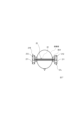
- FIG. 1 is a see-through perspective view illustrating the configuration of an acoustic signal output device 10.
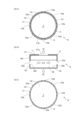
- Fig. 2A is a transparent plan view illustrating the configuration of the acoustic signal output device 10.
- Fig. 2B is a transparent front view illustrating the configuration of the acoustic signal output device 10.
- Fig. 2C is a bottom view illustrating the configuration of the acoustic signal output device 10.
- Figure 3A is an end view of 2BA-2BA of Figure 2B
- Figure 3B is an end view of 2A-2A of Figure 2A
- Figure 3C is an end view of 2BC-2BC of Figure 2B.
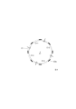
- FIG. 4 is a conceptual diagram illustrating the arrangement of sound holes.
- FIG. 4 is a conceptual diagram illustrating the arrangement of sound holes.
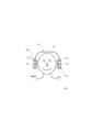
- FIG. 5 is a front view illustrating the configuration of the headphone device 20.
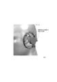
- FIG. 6 is a side view illustrating the configuration of the headphone device 20.
- FIG. 7 is a top view illustrating the configuration of the headphone device 20.
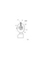
- FIG. 8 is a diagram illustrating a frame of the acoustic signal output device array 211.
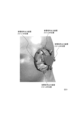
- FIG. 9 is a diagram illustrating an acoustic signal output device array 211 including four acoustic signal output devices 212 .
- a headphone device including an audio signal output device array including a plurality of audio signal output devices that realize local reproduction based on a dipole sound source.
- local reproduction based on a dipole sound source refers to reproduction utilizing the characteristic of a dipole sound source, in which the sound pressure is high only in the vicinity of the sound source and the sound pressure drops rapidly when moving away from the sound source.
- the reproduction method using a plurality of such audio signal output devices is theoretically equivalent to reproduction of a sound field based on the second kind of Rayleigh integral derived from the Kirchhoff-Helmholtz integral equation (see Reference Non-Patent Document 1).
- this reproduction method since the sound pressure is high only in the vicinity of each audio signal output device, sounds leaking from each audio signal output device do not interfere with each other, and it is possible to prevent amplification of sound leakage due to interference. Therefore, this reproduction method has the characteristic of less sound leakage to the surroundings.
- a dipole sound source is a sound source in which a positive phase sound source and a negative phase sound source are arranged adjacent to each other.
- a dipole sound source is described as an infinitesimal positive and negative dual sound source, the sound from the positive phase sound source and the sound from the negative phase sound source cancel each other out regardless of frequency, resulting in a directional characteristic of a figure of eight (see Reference Non-Patent Document 2).
- the size of the sound source is actually finite, the cancellation area becomes wider as the frequency of the sound that is easily diffracted (i.e., the wavelength is long).
- a single speaker driver unit can also be considered as a positive and negative dual sound source, so an acoustic signal output device that realizes local reproduction based on a dipole sound source can be configured using one speaker driver unit. An example of such a configuration will be described later.
- the Rayleigh integral of the second kind is an integral of the product of sound pressure and a dipole function on the plane S1, but in practice, the Rayleigh integral of the second kind can be regarded as the sum of the products of sound pressure and dipole function when dipole sound sources are discretely arranged. Therefore, a reproduction method using a plurality of sound signal output devices that realizes local reproduction based on a dipole sound source can be said to correspond to reproduction of a sound field based on the Rayleigh integral of the second kind.
- the acoustic signal output device 10 is an acoustic signal output device that outputs an acoustic signal from a dipole sound source, and can be used, for example, in open-ear headphones, which are acoustic listening devices worn without sealing the ear canal of a listener. As illustrated in Fig. 1, Fig. 2A, Fig. 2B, Fig. 2C, Fig. 3A, Fig. 3B, and Fig.
- the acoustic signal output device 10 has a driver unit 11 that converts an output signal (electrical signal representing an acoustic signal) output from a playback device into an acoustic signal and outputs it, and a housing 12 that houses the driver unit 11 inside.
- the driver unit (speaker driver unit) 11 is a device (device having a speaker function) that emits (emits sound) an acoustic signal AC1 (first acoustic signal) based on an input output signal to one side (D1 direction side) and emits an acoustic signal AC2 (second acoustic signal) that is an inverse phase signal (phase inversion signal) of the acoustic signal AC1 or an approximation signal of the inverse phase signal to the other side (D2 direction side).
- the acoustic signal emitted from the driver unit 11 to one side is called the acoustic signal AC1 (first acoustic signal)
- the acoustic signal emitted from the driver unit 11 to the other side is called the acoustic signal AC2 (second acoustic signal).
- the driver unit 11 includes a diaphragm 113 that emits the acoustic signal AC1 from one surface 113a in the D1 direction by vibration and emits the acoustic signal AC2 from the other surface 113b in the D2 direction by this vibration (see FIG. 2B).
- the driver unit 11 emits the acoustic signal AC1 from the surface 111 on one side in the D1 direction by vibrating the diaphragm 113 based on the input output signal, and emits the acoustic signal AC2, which is an inverse phase signal of the acoustic signal AC1 or an approximation of the inverse phase signal, from the other side 112 in the D2 direction. That is, the acoustic signal AC2 is emitted secondarily with the emission of the acoustic signal AC1.
- the D2 direction (the other side) is, for example, the opposite direction to the D1 direction (one side), but the D2 direction does not need to be strictly the opposite direction to the D1 direction, as long as the D2 direction is different from the D1 direction.
- the relationship between the one side (D1 direction) and the other side (D2 direction) depends on the type and shape of the driver unit 11.
- the acoustic signal AC2 may be strictly an inverse phase signal of the acoustic signal AC1, or the acoustic signal AC2 may be an approximation of the inverse phase signal of the acoustic signal AC1.
- the approximation signal of the opposite phase signal of the acoustic signal AC1 may be (1) a signal obtained by shifting the phase of the opposite phase signal of the acoustic signal AC1, (2) a signal obtained by changing (amplifying or attenuating) the amplitude of the opposite phase signal of the acoustic signal AC1, or (3) a signal obtained by shifting the phase of the opposite phase signal of the acoustic signal AC1 and further changing the amplitude.
- the phase difference between the opposite phase signal of the acoustic signal AC1 and its approximation signal is desirably ⁇ 1 % or less of one period of the opposite phase signal of the acoustic signal AC1.
- ⁇ 1 % are 1%, 3%, 5%, 10%, 20%, etc.
- the difference between the amplitude of the opposite phase signal of the acoustic signal AC1 and the amplitude of its approximation signal is desirably ⁇ 2 % or less of the amplitude of the opposite phase signal of the acoustic signal AC1.
- Examples of ⁇ 2 % are 1%, 3%, 5%, 10%, 20%, etc.
- examples of the type of the driver unit 11 include a dynamic type, a balanced armature chair type, a hybrid type of a dynamic type and a balanced armature type, and a condenser type.
- the shape of the driver unit 11 and the diaphragm 113 there is no limitation on the shape of the driver unit 11 and the diaphragm 113.
- the outer shape of the driver unit 11 is a substantially cylindrical shape with both end faces, and the diaphragm 113 is a substantially disc shape, but this does not limit the acoustic signal output device 10.
- the outer shape of the driver unit 11 may be a rectangular parallelepiped shape, and the diaphragm 113 may be a dome shape.
- examples of the acoustic signal are sounds such as music, voice, sound effects, and environmental sounds.
- acoustic signal AC1 and acoustic signal AC2 are acoustic signals from a positive-phase sound source and a negative-phase sound source, respectively.
- the housing 12 is a hollow member having a wall on the outside, and houses the driver unit 11 inside.
- the driver unit 11 is fixed to the end of the housing 12 on the D1 direction side.
- this does not limit the acoustic signal output device 10.
- the shape of the housing 12 is rotationally symmetric (line symmetric) or approximately rotationally symmetric about the axis A1 extending along the D1 direction. This makes it easy to provide a sound hole 123a (described in detail later) so that the variation in the energy of the sound emitted from the housing 12 for each direction is reduced. As a result, it becomes easy to reduce sound leakage uniformly in each direction.
- the housing 12 has a first end face which is a wall portion 121 arranged on one side (D1 direction side) of the driver unit 11, a second end face which is a wall portion 122 arranged on the other side (D2 direction side) of the driver unit 11, and a side face which is a wall portion 123 which surrounds the space between the first end face and the second end face and is centered on an axis line A1 passing through the first end face and the second end face (see FIG. 2B and FIG. 3B).
- the housing 12 has a substantially cylindrical shape with both end faces.
- the distance between the wall portion 121 and the wall portion 122 is 10 mm, and the walls 121 and 122 are circular with a radius of 10 mm.
- the housing 12 may be a substantially dome-shaped shape with walls at the ends, a hollow substantially cubic shape, or any other three-dimensional shape.
- the housing 12 may be made of a rigid body such as synthetic resin or metal, or may be made of an elastic body such as rubber.
- the wall of the housing 12 is provided with a sound hole 121a (first sound hole) for guiding the acoustic signal AC1 (first acoustic signal) emitted from the driver unit 11 to the outside, and a sound hole 121b (second sound hole) for guiding the acoustic signal AC2 (first acoustic signal) emitted from the driver unit 11 to the outside.
- the sound hole 121a and the sound hole 123a are, for example, through holes that penetrate the wall of the housing 12. However, this does not limit the acoustic signal output device 10. As long as the acoustic signals AC1 and AC2 can be output to the outside, the sound holes 121a and 123a do not have to be through holes. .
- the acoustic signal AC1 emitted from the sound hole 121a reaches the ear canal of the listener and is heard by the listener.
- an acoustic signal AC2 which is an inverse phase signal of the acoustic signal AC1 or an approximation of the inverse phase signal, is emitted from the sound hole 123a.
- a part of this acoustic signal AC2 cancels out a part of the acoustic signal AC1 emitted from the sound hole 121a (sound leakage component).
- the attenuation rate ⁇ 11 of the acoustic signal AC1 (first acoustic signal) at the position P2 (second point) based on the position P1 (first point) can be set to a predetermined value ⁇ th or less
- the attenuation amount ⁇ 12 of the acoustic signal AC1 (first acoustic signal) at the position P2 (second point) based on the position P1 (first point) can be set to a predetermined value ⁇ th or more.
- the position P1 (first point) is a predetermined point where the acoustic signal AC1 (first acoustic signal) emitted from the sound hole 121a (first sound hole) arrives.
- the position P2 (second point) is a predetermined point that is farther away from the acoustic signal output device 10 than the position P1 (first point).
- the predetermined value ⁇ th is a value smaller (lower) than the attenuation rate ⁇ 21 of an arbitrary or specific acoustic signal (sound) due to air propagation at a position P2 (second position) based on the position P1 (first position).
- the predetermined value ⁇ th is a value larger than the attenuation amount ⁇ 22 of an arbitrary or specific acoustic signal (sound) due to air propagation at a position P2 (second position) based on the position P1 (first position). That is, the acoustic signal output device 10 is designed so that the attenuation rate ⁇ 11 is equal to or smaller than a predetermined value ⁇ th smaller than the attenuation rate ⁇ 21 , or the attenuation amount ⁇ 12 is equal to or larger than a predetermined value ⁇ th larger than the attenuation amount ⁇ 22.
- the acoustic signal AC1 is propagated through the air from the position P1 to the position P2, and is attenuated due to this air propagation and the acoustic signal AC2.
- the attenuation rate ⁇ 11 is the ratio (AMP2 (AC1)/AMP1(AC1)) of the magnitude AMP2 (AC1) of the acoustic signal AC1 at position P2 attenuated due to air propagation and acoustic signal AC2 to the magnitude AMP1 (AC1) of the acoustic signal AC1 at position P1.
- the attenuation amount ⁇ 12 is the difference (
- any or a specific acoustic signal ACar propagated through the air from position P1 to position P2 is attenuated due to air propagation, not due to the acoustic signal AC2.
- the attenuation rate ⁇ 21 is the ratio ( AMP2(ACar)/AMP1 ( ACar )) of the magnitude AMP2 ( ACar ) of the acoustic signal ACar at position P2 attenuated due to air propagation (attenuation without being due to the acoustic signal AC2) to the magnitude AMP1( ACar ) of the acoustic signal ACar at position P1.
- the attenuation amount ⁇ 22 is the difference (
- the magnitude of the acoustic signal include the sound pressure of the acoustic signal or the energy of the acoustic signal.
- the "sound leakage component" means, for example, a component of the acoustic signal AC1 emitted from the sound hole 121a that is likely to reach an area other than that of the listener wearing the acoustic signal output device 10 (for example, a person other than the listener wearing the acoustic signal output device 10).
- the "sound leakage component” means a component of the acoustic signal AC1 that propagates in a direction other than the D1 direction.
- the direct wave of the acoustic signal AC1 is mainly emitted from the sound hole 121a
- the direct wave of the second acoustic signal is mainly emitted from the second sound hole.
- a part of the direct wave of the acoustic signal AC1 emitted from the sound hole 121a (sound leakage component) is offset by interference with at least a part of the direct wave of the acoustic signal AC2 emitted from the sound hole 123a.
- this does not limit the acoustic signal output device 10, and this offsetting can occur with other than direct waves.
- the sound leakage component which is at least one of the direct wave and the reflected wave of the acoustic signal AC1 emitted from the sound hole 121a, may be cancelled out by at least one of the direct wave and the reflected wave of the acoustic signal AC2 emitted from the sound hole 123a. This makes it possible to suppress sound leakage.
- the following shows an example of the arrangement of sound holes 121a and 123a.
- Sound hole 121a (first sound hole) is provided in area AR1 (first area) of wall 121 arranged on one side of driver unit 11 (the D1 direction side where acoustic signal AC1 is emitted) (see Figures 1, 2A, 2B, and 3B). That is, sound hole 121a opens facing the D1 direction (first direction) along axis A1. Also, sound hole 123a (second sound hole) is provided in area AR3 of wall 123 adjacent to area AR between area AR1 (first area) of wall 121 of housing 12 and area AR2 (second area) of wall 122 arranged on the D2 direction side of driver unit 11 (the other side where acoustic signal AC2 is emitted).
- the sound hole 121a first sound hole
- the sound hole 123a second sound hole
- the housing 12 has a first end face which is a wall portion 121 arranged on one side (D1 direction side) of the driver unit 11, a second end face which is a wall portion 122 arranged on the other side (D2 direction side) of the driver unit 11, and a side face which is a wall portion 123 which surrounds the space between the first end face and the second end face and is centered on an axis A1 along the emission direction (D1 direction) of the acoustic signal AC1 passing through the first end face and the second end face (see FIG. 2B and FIG. 3B), the sound hole 121a (first sound hole) is provided on the first end face, and the sound hole 123a (second sound hole) is provided on the side face.
- no sound hole is provided on the wall portion 122 side of the housing 12. If a sound hole is provided on the wall portion 122 side of the housing 12, the sound pressure level of the acoustic signal AC2 emitted from the housing 12 exceeds the level necessary to offset the sound leakage component of the acoustic signal AC1, and the excess is perceived as sound leakage.
- the sound hole 121a is disposed on or near the axis A1 along the emission direction (D1 direction) of the acoustic signal AC1.
- the axis A1 passes through the center or near the center of the area AR1 (first area) of the wall 121 disposed on one side (D1 direction side) of the driver unit 11 of the housing 12.
- the axis A1 is an axis extending in the D1 direction through the central area of the housing 12. That is, the sound hole 121a is provided at the central position of the area AR1 of the wall 121 of the housing 12.
- the edge shape of the open end of the sound hole 121a is a circle (the open end is circular).
- the radius of such a sound hole 121a is, for example, 3.5 mm.
- this does not limit the acoustic signal output device 10.
- the edge shape of the open end of the sound hole 121a may be other shapes such as an ellipse, a rectangle, a triangle, etc.
- the open end of the sound hole 121a may be in a mesh pattern. In other words, the open end of the sound hole 121a may be composed of multiple holes.
- one sound hole 121a is provided in the area AR1 (first area) of the wall 121 of the housing 12.
- this does not limit the acoustic signal output device 10.
- two or more sound holes 121a may be provided in the area AR1 (first area) of the wall 121 of the housing 12.
- the sound hole 123a (second sound hole) be positioned taking into consideration the following points, for example:
- Sound hole 123a is positioned so that the propagation path of the sound leakage component of sound signal AC1 to be cancelled overlaps with the propagation path of sound signal AC2 emitted from sound hole 123a.
- the propagation area of the acoustic signal AC2 emitted from the sound hole 123a and the frequency characteristics of the housing 12 vary depending on the opening area of the sound hole 123a. Furthermore, the frequency characteristics of the housing 12 affect the frequency characteristics of the acoustic signal AC2 emitted from the sound hole 123a, i.e., the amplitude at each frequency. Taking into consideration the propagation area and frequency characteristics of the acoustic signal AC2 emitted from the sound hole 123a, the opening area of the sound hole 123a is determined so that in the area where the sound leakage components are to be cancelled out, the sound leakage components are cancelled out by the acoustic signal AC2 emitted from the sound hole 123a.
- the sound hole 123a (second sound hole) be configured as follows, for example.
- the sound holes 123a are provided along a circumference (circle) C1 centered on the axis A1 along the emission direction of the acoustic signal AC1 (first acoustic signal).
- the acoustic signal AC2 is emitted radially (radially centered on the axis A1) from the sound holes 123a to the outside.
- the sound leakage component of the acoustic signal AC1 is also emitted radially (radially centered on the axis A1) from the sound hole 121a to the outside.
- the sound leakage component of the acoustic signal AC1 can be appropriately canceled by the acoustic signal AC2.
- an example is shown in which multiple sound holes 123a are provided on the circumference C1.
- the multiple sound holes 123a are provided along the circumference C1, and it is not necessary that all of the sound holes 123a are positioned strictly on the circumference C1.
- the sum of the opening areas of the sound holes 123a (second sound holes) provided along a first arc region, which is any of the unit arc regions, is the same or approximately the same as the sum of the opening areas of the sound holes 123a (second sound holes) provided along a second arc region, which is any of the unit arc regions excluding the first arc region.
- the sum of the opening areas of the sound holes 123a (second sound holes) provided along a first arc region which is any of the unit arc regions
- the sum of the opening areas of the sound holes 123a (second sound holes) provided along a second arc region which is any of the unit arc regions excluding the first arc region.
- the sum of the opening areas of the sound holes 123a (second sound holes) provided along a first arc region (for example, unit arc region C1-1) that is one of the unit arc regions C1-1, ..., C1-4 is the same or approximately the same as the sum of the opening areas of the sound holes 123a (second sound holes) provided along a second arc region (for example, unit arc region C1-2) that is one of the unit arc regions excluding the first arc region.
- the sound pressure distribution of the acoustic signal AC2 emitted from the sound hole 123a provided along the first arc region and the sound pressure distribution of the acoustic signal AC2 emitted from the sound hole 123a provided along the second arc region are point symmetric or approximately point symmetric with respect to the axis A1.
- the sums of the opening areas of the sound holes 123a (second sound holes) provided along each unit arc region are all the same or approximately the same.
- the sound pressure distribution of the acoustic signal AC2 emitted from the sound hole 123a is point symmetric or approximately point symmetric with respect to the axis A1.
- the sound leakage component of the acoustic signal AC1 can be more appropriately canceled out by the acoustic signal AC2.
- the multiple sound holes 123a are arranged along the circumference C1 with the same shape, size, and spacing.
- multiple sound holes 123a with a width of 4 mm and a height of 3.5 mm are arranged along the circumference C1 with the same shape, size, and spacing.
- the sound leakage components of the acoustic signal AC1 can be more appropriately cancelled out by the acoustic signal AC2.
- sound hole 123a (second sound hole) is provided in a wall portion adjacent to area AR located on the other side (D2 direction side) of driver unit 11 (see FIG. 3B). This allows the direct wave of acoustic signal AC2 emitted from the other side of driver unit 11 to be efficiently guided to the outside from sound hole 123a. As a result, the sound leakage component of acoustic signal AC1 can be more appropriately cancelled out by acoustic signal AC2.
- the edge of the open end of the sound hole 123a is rectangular (the open end is square), but this does not limit the acoustic signal output device 10.
- the edge of the open end of the sound hole 123a may be circular, elliptical, triangular, or other shapes.
- the open end of the sound hole 123a may also be mesh-like.
- the open end of the sound hole 123a may be composed of multiple holes.
- There is also no limit to the number of sound holes 123a and a single sound hole 123a may be provided in the area AR3 of the wall 123 of the housing 12, or multiple sound holes 123a may be provided.
- the ratio S2 / S1 of the sum S2 of the opening areas of the sound holes 123a (second sound holes) to the sum S1 of the opening areas of the sound holes 121a (first sound holes) satisfies 2/3 ⁇ S2 / S1 ⁇ 4. This allows the sound leakage component of the acoustic signal AC1 to be appropriately cancelled out by the acoustic signal AC2.
- the sound leakage suppression performance may also depend on the ratio between the area of the wall 123 in which the sound hole 123a is provided and the opening area of the sound hole 123a.
- the housing 12 has a first end face which is the wall 121 arranged on one side (D1 direction side) of the driver unit 11, a second end face which is the wall 122 arranged on the other side (D2 direction side) of the driver unit 11, and a side face which is the wall 123 surrounding the space between the first end face and the second end face around the axis A1 along the emission direction (D1 direction) of the acoustic signal AC1 passing through the first end face and the second end face, and the sound hole 121a (first sound hole) is provided on the first end face, and the sound hole 123a (second sound hole) is provided on the side face (see FIG.
- the ratio S2 / S3 of the sum S2 of the opening areas of the sound holes 123a to the total area S3 of the side surfaces is 1/20 ⁇ S2 / S3 ⁇ 1/5. This allows the sound leakage component of the acoustic signal AC1 to be appropriately cancelled by the acoustic signal AC2. However, this does not limit the acoustic signal output device 10.
- Fig. 5 to Fig. 7 are all diagrams showing the configuration of the headphone device 20, with Fig. 5 being a front view of the headphone device 20 seen from the front, Fig. 6 being a side view of the headphone device 20 seen from the left side, and Fig. 7 being a top view of the headphone device 20 seen from above.
- the headphone device 20 includes a right headphone 21R, a left headphone 21L, and a headband 22.
- the headphone device 20 is configured such that the right headphone 21R and the left headphone 21L are connected to the left and right ends of the headband 22.
- Both the right headphone 21R and the left headphone 21L have an acoustic signal output device array 211.
- the acoustic signal output device array 211 includes a plurality of acoustic signal output devices 212 arranged to surround the pinna of the listener (see Fig. 6).
- the acoustic signal output device 212 is an acoustic signal output device that realizes local reproduction based on a dipole sound source, and is, for example, the acoustic signal output device 10 described in ⁇ Technical Background>. Therefore, the acoustic signal output device array 211 is configured to reproduce a sound field based on the Rayleigh integral of the second kind in the vicinity of the pinna.
- the acoustic signal output device array 211 is configured as a frame-like structure surrounding the auricle, which serves as the framework of the headphone device 20, and multiple acoustic signal output devices 212 may be provided on the frame so as to surround the auricle (see FIG. 8).
- the headphone device 20 becomes an open-type headphone, which allows the headphone device 20 to take in sounds around the listener without blocking them, and allows the listener to easily hear sounds that warn of danger, such as horns, warning sounds, and alarms, even when the headphone device 20 is used outdoors.
- the input signals of the acoustic signal output devices 212 included in the acoustic signal output device array 211 are signals obtained by signal processing of electrical signals representing acoustic signals based on physical quantities determined by the positional relationship between the virtual sound source and the acoustic signal output device in order to localize the virtual sound source. Examples of physical quantities are described below.
- the acoustic signal output device array 211 included in the right headphone 21R includes four acoustic signal output devices 212-R1, acoustic signal output device 212-R2, acoustic signal output device 212-R3, and acoustic signal output device 212-R4, and the acoustic signal output device array 211 included in the left headphone 21L includes four acoustic signal output devices 212-L1, acoustic signal output device 212-L2, acoustic signal output device 212-L3, and acoustic signal output device 212-L4 (see FIG. 9).
- Example 1 Phase Difference of Acoustic Signals
- the distances between the virtual sound source and the acoustic signal output device 212-L1, the distance between the virtual sound source and the acoustic signal output device 212-L2, the distance between the virtual sound source and the acoustic signal output device 212-L3, and the distance between the virtual sound source and the acoustic signal output device 212-L4 are r(L1), r(L2), r(L3), and r(L4), respectively, and the speed of sound is c
- the time Delay(L2) that it takes for the sound emitted from the virtual sound source to reach the acoustic signal output device 212-L2 the time
- a signal obtained by performing signal processing to impart a phase difference to an electrical signal representing an acoustic signal based on a delay equivalent to sample time Ts(L1) (i.e., the phase difference between the acoustic signals) is set as the input signal for the acoustic signal output device 212-L1.
- a signal obtained by performing signal processing to impart a phase difference to an electrical signal representing an acoustic signal based on a delay equivalent to sample time Ts(L2) is set as the input signal for the acoustic signal output device 212-L2
- a signal obtained by performing signal processing to impart a phase difference to an electrical signal representing an acoustic signal based on a delay equivalent to sample time Ts(L3) is set as the input signal for the acoustic signal output device 212-L3
- a signal obtained by performing signal processing to impart a phase difference to an electrical signal representing an acoustic signal based on a delay equivalent to sample time Ts(L4) is set as the input signal for the acoustic signal output device 212-L4.
- the phase difference may be determined based on the time Delay(L1) that it takes for sound emitted from a virtual sound source to reach the audio signal output device 212-L1.
- Example 2 Amplitude difference of acoustic signals
- the position of a virtual sound source may be localized using the amplitude difference of acoustic signals.
- Example 1 consider a situation in which a sound emitted from a virtual sound source reaches the acoustic signal output device array 211 included in the left headphone 21L. Also, assume that the sound from the virtual sound source is a spherical wave. In this case, distance attenuation 1/r(L1) occurs before the sound emitted from the virtual sound source reaches the acoustic signal output device 212-L1.
- a signal obtained by performing signal processing to adjust the amplitude of an electrical signal representing an acoustic signal based on the amplitude difference of acoustic signals equivalent to the distance attenuation 1/r(L1) is used as the input signal to the acoustic signal output device 212-L1.
- a signal obtained by performing signal processing to adjust the amplitude of an electrical signal representing an acoustic signal based on an amplitude difference between acoustic signals equivalent to distance attenuation 1/r(L2) is the input signal to acoustic signal output device 212-L2
- a signal obtained by performing signal processing to adjust the amplitude of an electrical signal representing an acoustic signal based on an amplitude difference between acoustic signals equivalent to distance attenuation 1/r(L3) is the input signal to acoustic signal output device 212-L3
- a signal obtained by performing signal processing to adjust the amplitude of an electrical signal representing an acoustic signal based on an amplitude difference between acoustic signals equivalent to distance attenuation 1/r(L4) is the input signal to acoustic signal output device 212-L4.
- signal processing to adjust the amplitude of an electrical signal representing an acoustic signal refers to signal processing in which the amplitude of
- Example 3 Phase difference and amplitude difference of acoustic signals
- the position of a virtual sound source may be localized using the phase difference and amplitude difference of acoustic signals.
- Example 1 consider a situation in which a sound emitted from a virtual sound source reaches the acoustic signal output device array 211 included in the left headphone 21L. Also assume that the sound from the virtual sound source is a spherical wave.
- the phase difference and amplitude difference that occur when the sound emitted from the virtual sound source reaches the acoustic signal output device 212-L1 can be expressed as exp(-jkr(L1))/r(L1).
- a signal obtained by performing signal processing to adjust the phase difference and amplitude of an electrical signal representing an acoustic signal based on the phase difference and amplitude difference of the acoustic signal equivalent to exp(-jkr(L1))/r(L1) is used as the input signal of the acoustic signal output device 212-L1.
- a signal obtained by performing signal processing to adjust the phase difference and amplitude of an electrical signal representing an acoustic signal based on the phase difference and amplitude difference of an acoustic signal equivalent to exp(-jkr(L2))/r(L2) is set as an input signal for the acoustic signal output device 212-L2
- a signal obtained by performing signal processing to adjust the phase difference and amplitude of an electrical signal representing an acoustic signal based on the phase difference and amplitude difference of an acoustic signal equivalent to exp(-jkr(L3))/r(L3) is set as an input signal for the acoustic signal output device 212-L3
- a signal obtained by performing signal processing to adjust the phase difference and amplitude of an electrical signal representing an acoustic signal based on the phase difference and amplitude difference of an acoustic signal equivalent to exp(-jkr(L4))/r(L4) is set as an input signal for the acoustic
- FIG. 6 illustrates an acoustic signal output device array 211 in which multiple acoustic signal output devices 212 are arranged in a circle
- the arrangement shape does not necessarily have to be circular, and may be elliptical, rectangular, or even other shapes. In other words, it is sufficient that the multiple acoustic signal output devices 212 are arranged so as to surround the auricle.
Landscapes
- Physics & Mathematics (AREA)
- Engineering & Computer Science (AREA)
- Acoustics & Sound (AREA)
- Signal Processing (AREA)
- Health & Medical Sciences (AREA)
- Otolaryngology (AREA)
- Soundproofing, Sound Blocking, And Sound Damping (AREA)
Abstract
Description
本発明は、複数の音響信号出力装置を用いて構成されるヘッドホン装置に関する。 The present invention relates to a headphone device that is configured using multiple audio signal output devices.
複数のスピーカを用いて任意の位置に仮想的音源を定位させる技術として、非特許文献1や非特許文献2に記載の技術がある。非特許文献1では、頭部音響伝達関数(Head Related Transfer Function: HRTF)を用いて仮想的音源を定位させる。また、非特許文献2では、波面合成法により到来する波面を耳の周りに模擬することで仮想的音源を定位させる。 Technologies for localizing a virtual sound source at any position using multiple speakers include those described in Non-Patent Document 1 and Non-Patent Document 2. In Non-Patent Document 1, the virtual sound source is localized using the Head Related Transfer Function (HRTF). In Non-Patent Document 2, the virtual sound source is localized by simulating the incoming wavefront around the ear using wave field synthesis.
複数のスピーカを用いる代わりにスピーカに相当する音響信号出力装置を複数備えるヘッドホンを用いることにより、仮想的音源を定位することもできる。しかし、非特許文献1や非特許文献2に記載の技術を用いると、仮想的音源を定位させるために必要となる演算量が大きくなってしまう。 Instead of using multiple speakers, it is also possible to localize a virtual sound source by using headphones equipped with multiple audio signal output devices equivalent to speakers. However, when using the techniques described in Non-Patent Document 1 and Non-Patent Document 2, the amount of calculation required to localize the virtual sound source becomes large.
そこで本発明では、演算量を抑えつつ任意の位置に仮想的音源を定位させる、複数の音響信号出力装置を用いたヘッドホン装置を提供することを目的とする。 The present invention aims to provide a headphone device that uses multiple audio signal output devices and localizes a virtual sound source at any position while minimizing the amount of calculations.
本発明の一態様は、耳介を取り囲むように配置された複数の、ダイポール音源に基づく局所再生を実現する音響信号出力装置を含む音響信号出力装置アレーを含むヘッドホン装置であって、前記音響信号出力装置アレーに含まれる音響信号出力装置の入力信号は、仮想的音源を定位させるために当該仮想的音源と当該音響信号出力装置との位置関係により定まる物理量に基づいて音響信号を表す電気信号を信号処理することにより得られる信号である。 One aspect of the present invention is a headphone device including an acoustic signal output device array including acoustic signal output devices that realize localized reproduction based on a dipole sound source arranged to surround the auricle, and the input signal of the acoustic signal output device included in the acoustic signal output device array is a signal obtained by signal processing an electrical signal representing an acoustic signal based on a physical quantity determined by the positional relationship between the virtual sound source and the acoustic signal output device in order to localize the virtual sound source.
本発明によれば演算量を抑えつつ任意の位置に仮想的音源を定位させることが可能となる。 The present invention makes it possible to localize a virtual sound source at any position while minimizing the amount of calculation required.
以下、本発明の実施の形態について、詳細に説明する。なお、同じ機能を有する構成部には同じ番号を付し、重複説明を省略する。 Below, an embodiment of the present invention will be described in detail. Components having the same functions will be given the same numbers, and duplicate explanations will be omitted.
<技術的背景>
本発明の実施形態では、ダイポール音源に基づく局所再生を実現する音響信号出力装置を複数含む音響信号出力装置アレーを含むヘッドホン装置を用いる。ここで、ダイポール音源に基づく局所再生とは、音源の近傍のみ音圧が高く、当該音源から離れると音圧が急激に低くなるというダイポール音源の特徴を利用した再生のことである。当該音響信号出力装置を複数用いた再生方法は、理論的にはキルヒホッフ-ヘルムホルツ積分方程式から導出される第二種レイリー(Rayleigh)積分に基づく音場の再現に相当するものである(参考非特許文献1参照)。また、当該再生方法では、各音響信号出力装置の近傍のみ音圧が高いため、各音響信号出力装置から漏れる音が干渉することがなく、干渉による音漏れの増幅を防ぐことができる。そのため、当該再生方法は、周囲への音漏れが少ないという特徴がある。
<Technical Background>
In an embodiment of the present invention, a headphone device including an audio signal output device array including a plurality of audio signal output devices that realize local reproduction based on a dipole sound source is used. Here, local reproduction based on a dipole sound source refers to reproduction utilizing the characteristic of a dipole sound source, in which the sound pressure is high only in the vicinity of the sound source and the sound pressure drops rapidly when moving away from the sound source. The reproduction method using a plurality of such audio signal output devices is theoretically equivalent to reproduction of a sound field based on the second kind of Rayleigh integral derived from the Kirchhoff-Helmholtz integral equation (see Reference Non-Patent Document 1). In addition, in this reproduction method, since the sound pressure is high only in the vicinity of each audio signal output device, sounds leaking from each audio signal output device do not interfere with each other, and it is possible to prevent amplification of sound leakage due to interference. Therefore, this reproduction method has the characteristic of less sound leakage to the surroundings.
(参考非特許文献1:安藤彰男,“物理音響モデルに基づく音響システムの研究動向,”NHK技研R&D 2011年3月号 解説02,2011.)
以下では、ダイポール音源に基づく局所再生と、ダイポール音源に基づく局所再生を実現する音響信号出力装置を複数用いた再生方法が第二種レイリー積分に基づく音場の再現に相当することについて説明する。
(Reference non-patent document 1: Akio Ando, "Research trends in acoustic systems based on physical acoustic models," NHK STRL R&D, March 2011 issue, Commentary 02, 2011.)
In the following, it will be explained that local reproduction based on a dipole sound source and a reproduction method using multiple acoustic signal output devices to realize local reproduction based on a dipole sound source correspond to reproduction of a sound field based on the Rayleigh integral of the second kind.
まず、ダイポール音源に基づく局所再生について説明する。ダイポール音源は、正相の音源と逆相の音源とが隣接して配置されたものである。ダイポール音源が無限小の正負二重音源として記述される場合、周波数によらず正相の音源からの音と逆相の音源からの音とが相殺し、8の字の指向特性が得られる(参考非特許文献2参照)。しかし、実際には音源のサイズは有限であるため、回折し易い周波数が低い(つまり、波長が長い)音ほど相殺する領域は広くなる。ただし、正相の音源の近傍では、逆相の音源からの音の回折の過程で生じる距離減衰と位相差のため、正相の音源からの音と逆相の音源からの音との完全な相殺には至らない。このため、ダイポール音源を用いると局所再生が可能となる。なお、スピーカードライバーユニット単体も正負二重音源とみなすことができるため、1つのスピーカードライバーユニットを用いてダイポール音源に基づく局所再生を実現する音響信号出力装置を構成することができる。このような構成例については後述する。 First, local reproduction based on a dipole sound source will be described. A dipole sound source is a sound source in which a positive phase sound source and a negative phase sound source are arranged adjacent to each other. When a dipole sound source is described as an infinitesimal positive and negative dual sound source, the sound from the positive phase sound source and the sound from the negative phase sound source cancel each other out regardless of frequency, resulting in a directional characteristic of a figure of eight (see Reference Non-Patent Document 2). However, since the size of the sound source is actually finite, the cancellation area becomes wider as the frequency of the sound that is easily diffracted (i.e., the wavelength is long). However, in the vicinity of the positive phase sound source, the sound from the positive phase sound source and the sound from the negative phase sound source do not cancel out completely due to the distance attenuation and phase difference that occur in the process of diffraction of the sound from the negative phase sound source. For this reason, local reproduction is possible when a dipole sound source is used. Note that a single speaker driver unit can also be considered as a positive and negative dual sound source, so an acoustic signal output device that realizes local reproduction based on a dipole sound source can be configured using one speaker driver unit. An example of such a configuration will be described later.
(参考非特許文献2:西巻正郎,“改版電気音響振動学,” コロナ社,pp.58-59, 1980.)
次に、ダイポール音源に基づく局所再生を実現する音響信号出力装置を複数用いた再生方法が第二種レイリー積分に基づく音場の再現に相当することについて説明する。参考非特許文献1によると、キルヒホッフ-ヘルムホルツ積分方程式は第一種レイリー積分と第二種レイリー積分に変形できる(参考非特許文献1の式(4),(5)参照)。ここで音圧を速度ポテンシャルとして扱うこととすると、音圧の空間微分は粒子速度に相当する。境界となる平面S1が剛体である場合、平面S1上の粒子速度はゼロとなるため、第一種レイリー積分は消失する。また、参考非特許文献1の式(5)からわかるように、第二種レイリー積分は平面S1上で音圧とダイポール関数との積を積分するものであるが、実用上、第二種レイリー積分はダイポール音源を離散的に配置した場合における音圧とダイポール関数との積を加算したものとみなすことができる。したがって、ダイポール音源に基づく局所再生を実現する音響信号出力装置を複数用いた再生方法は、第二種レイリー積分に基づく音場の再現に相当するといえる。
(Reference non-patent document 2: Masao Nishimaki, "Revised Edition of Electroacoustic Vibration Science," Corona Publishing, pp. 58-59, 1980.)
Next, it will be explained that the reproduction method using a plurality of sound signal output devices that realizes local reproduction based on a dipole sound source corresponds to reproduction of a sound field based on the Rayleigh integral of the second kind. According to the reference non-patent document 1, the Kirchhoff-Helmholtz integral equation can be transformed into the Rayleigh integral of the first kind and the Rayleigh integral of the second kind (see formulas (4) and (5) in the reference non-patent document 1). If sound pressure is treated as a velocity potential, the spatial derivative of sound pressure corresponds to particle velocity. If the boundary plane S1 is a rigid body, the particle velocity on the plane S1 becomes zero, so the Rayleigh integral of the first kind disappears. In addition, as can be seen from formula (5) in the reference non-patent document 1, the Rayleigh integral of the second kind is an integral of the product of sound pressure and a dipole function on the plane S1, but in practice, the Rayleigh integral of the second kind can be regarded as the sum of the products of sound pressure and dipole function when dipole sound sources are discretely arranged. Therefore, a reproduction method using a plurality of sound signal output devices that realizes local reproduction based on a dipole sound source can be said to correspond to reproduction of a sound field based on the Rayleigh integral of the second kind.
<<ダイポール音源に基づく局所再生を実現する音響信号出力装置の構成例>>
[構成]
音響信号出力装置10は、ダイポール音源からの音響信号を出力する音響信号出力装置であり、例えば、受聴者の外耳道を密閉せずに装着される音響聴取用装置である開放型(オープンイヤー型)ヘッドホンに用いることができる。図1、図2A、図2B、図2C、図3A、図3B、図3Cに例示するように、音響信号出力装置10は、再生装置から出力された出力信号(音響信号を表す電気信号)を音響信号に変換して出力するドライバーユニット11と、ドライバーユニット11を内部に収容している筐体12とを有する。
<<Example of configuration of an acoustic signal output device that realizes local reproduction based on a dipole sound source>>
[composition]
The acoustic
[ドライバーユニット11]
ドライバーユニット(スピーカードライバーユニット)11は、入力された出力信号に基づく音響信号AC1(第1音響信号)を一方側(D1方向側)へ放出(放音)し、音響信号AC1の逆位相信号(位相反転信号)または逆位相信号の近似信号である音響信号AC2(第2音響信号)を他方側(D2方向側)に放出する装置(スピーカー機能を持つ装置)である。すなわち、ドライバーユニット11から一方側(D1方向側)へ放出される音響信号を音響信号AC1(第1音響信号)と呼び、ドライバーユニット11から他方側(D2方向側)に放出される音響信号を音響信号AC2(第2音響信号)と呼ぶことにする。例えば、ドライバーユニット11は、振動によって一方の面113aから音響信号AC1をD1方向側に放出し、この振動によって他方の面113bから音響信号AC2をD2方向側に放出する振動板113を含む(図2B参照)。この例のドライバーユニット11は、入力された出力信号に基づいて振動板113が振動することで、音響信号AC1を一方側の面111からD1方向側へ放出し、音響信号AC1の逆位相信号または逆位相信号の近似信号である音響信号AC2を他方側の側112からD2方向側へ放出する。すなわち、音響信号AC2は、音響信号AC1の放出に伴って副次的に放出されるものである。なお、D2方向(他方側)は、例えばD1方向(一方側)の逆方向であるが、D2方向が厳密にD1方向の逆方向である必要はなく、D2方向がD1方向と異なっていればよい。一方側(D1方向)と他方側(D2方向)との関係は、ドライバーユニット11の方式や形状に依存する。また、ドライバーユニット11の方式や形状によって、音響信号AC2が厳密に音響信号AC1の逆位相信号となる場合もあれば、音響信号AC2が音響信号AC1の逆位相信号の近似信号となる場合がある。例えば、音響信号AC1の逆位相信号の近似信号は、(1)音響信号AC1の逆位相信号の位相をシフトして得られる信号であってもよいし、(2)音響信号AC1の逆位相信号の振幅を変化(増幅または減衰)させて得られる信号であってもよいし、(3)音響信号AC1の逆位相信号の位相をシフトし、さらに振幅を変化させて得られる信号であってもよい。音響信号AC1の逆位相信号とその近似信号との位相差は、音響信号AC1の逆位相信号の一周期のδ1%以下であることが望ましい。δ1%の例は1%,3%,5%,10%,20%などである。また、音響信号AC1の逆位相信号の振幅とその近似信号の振幅との差分は、音響信号AC1の逆位相信号の振幅のδ2%以下であることが望ましい。δ2%の例は1%,3%,5%,10%,20%などである。なお、ドライバーユニット11の方式としては、ダイナミック型、バランスドアーマチェア型、ダイナミック型とバランスドアーマチュア型のハイブリッド型、コンデンサー型などを例示できる。また、ドライバーユニット11や振動板113の形状に限定はない。ここでは、説明の簡略化のため、ドライバーユニット11の外形が両端面を持つ略円筒形状であり、振動板113が略円盤形状である例を示すが、これは音響信号出力装置10を限定するものではない。例えば、ドライバーユニット11の外形が直方体形状などであってもよいし、振動板113がドーム形状などであってもよい。また、音響信号の例は、音楽、音声、効果音、環境音などの音である。
[Driver unit 11]
The driver unit (speaker driver unit) 11 is a device (device having a speaker function) that emits (emits sound) an acoustic signal AC1 (first acoustic signal) based on an input output signal to one side (D1 direction side) and emits an acoustic signal AC2 (second acoustic signal) that is an inverse phase signal (phase inversion signal) of the acoustic signal AC1 or an approximation signal of the inverse phase signal to the other side (D2 direction side). That is, the acoustic signal emitted from the
ここで、音響信号AC1、音響信号AC2がそれぞれ正相の音源からの音響信号、逆相の音源からの音響信号であることに留意する。 Note that acoustic signal AC1 and acoustic signal AC2 are acoustic signals from a positive-phase sound source and a negative-phase sound source, respectively.
[筐体12]
筐体12は、外側に壁部を持つ中空の部材であり、内部にドライバーユニット11を収納している。例えば、ドライバーユニット11は、筐体12内部のD1方向側の端部に固定されている。しかし、これは音響信号出力装置10を限定するものではない。筐体12の形状にも限定はないが、例えば、筐体12の形状が、D1方向に沿って伸びる軸線A1を中心とした回転対称(線対称)または略回転対称であることが望ましい。これにより、筐体12から放出される音のエネルギーの方向ごとのばらつきが小さくなるように音孔123a(詳細は後述)を設けることが容易となる。その結果、各方向に均一に音漏れを軽減することが容易になる。例えば、筐体12は、ドライバーユニット11の一方側(D1方向側)に配置された壁部121である第1端面と、ドライバーユニット11の他方側(D2方向側)に配置された壁部122である第2端面と、第1端面と第2端面とで挟まれた空間を、第1端面と第2端面とを通る軸線A1を中心に取り囲む壁部123である側面とを有する(図2B及び図3B参照)。ここでは、説明の簡略化のため、筐体12が両端面を持つ略円筒形状である例を示す。例えば、壁部121と壁部122との間隔が10mmであり、壁部121,122が半径10mmの円形である。しかし、これらは一例であって音響信号出力装置10を限定するものではない。例えば、筐体12が、端部に壁部を持つ略ドーム型形状であってもよいし、中空の略立方体形状であってもよいし、その他の立体形状であってもよい。また、筐体12を構成する材質にも限定はない。筐体12が合成樹脂や金属などの剛体によって構成されていてもよいし、ゴムなどの弾性体によって構成されていてもよい。
[Housing 12]
The
[音孔121a,123a]
筐体12の壁部には、ドライバーユニット11から放出された音響信号AC1(第1音響信号)を外部に導出する音孔121a(第1音孔)と、ドライバーユニット11から放出された音響信号AC2(第2音響信号)を外部に導出する音孔123a(第2音孔)とが設けられている。音孔121aおよび音孔123aは、例えば、筐体12の壁部を貫通する貫通孔であるが、これは音響信号出力装置10を限定するものではない。音響信号AC1および音響信号AC2をそれぞれ外部に導出できるのであれば、音孔121aおよび音孔123aが貫通孔でなくてもよい。
[
The wall of the
音孔121aから放出された音響信号AC1は受聴者の外耳道に届き、受聴者に聴取される。一方、音孔123aからは、音響信号AC1の逆位相信号または逆位相信号の近似信号である音響信号AC2が放出される。この音響信号AC2の一部は、音孔121aから放出された音響信号AC1の一部(音漏れ成分)を相殺する。すなわち、音孔121a(第1音孔)から音響信号AC1(第1音響信号)が放出され、音孔123a(第2音孔)から音響信号AC2(第2音響信号)が放出されることで、位置P1(第1地点)を基準とした位置P2(第2地点)での音響信号AC1(第1音響信号)の減衰率η11を予め定めた値ηth以下とすることができたり、位置P1(第1地点)を基準とした位置P2(第2地点)での音響信号AC1(第1音響信号)の減衰量η12を予め定めた値ωth以上とできたりする。ここで、位置P1(第1地点)は、音孔121a(第1音孔)から放出された音響信号AC1(第1音響信号)が到達する予め定められた地点である。一方、位置P2(第2地点)は、音響信号出力装置10からの距離が位置P1(第1地点)よりも遠い予め定められた地点である。予め定めた値ηthは、位置P1(第1地点)を基準とした位置P2(第2地点)での任意または特定の音響信号(音)の空気伝搬による減衰率η21よりも小さい値(低い値)である。また、予め定めた値ωthは、位置P1(第1地点)を基準とした位置P2(第2地点)での任意または特定の音響信号(音)の空気伝搬による減衰量η22よりも大きい値である。すなわち、音響信号出力装置10は、減衰率η11が、減衰率η21よりも小さい予め定めた値ηth以下となるように設計されているか、または、減衰量η12が、減衰量η22よりも大きい予め定めた値ωth以上となるように設計されている。なお、音響信号AC1は位置P1から位置P2まで空気伝搬され、この空気伝搬と音響信号AC2とに起因して減衰する。減衰率η11は、位置P1での音響信号AC1の大きさAMP1(AC1)に対する、空気伝搬と音響信号AC2とに起因して減衰した位置P2での音響信号AC1の大きさAMP2(AC1)の比率(AMP2(AC1)/AMP1(AC1))である。また、減衰量η12は、大きさAMP1(AC1)と大きさAMP2(AC1)との差分(|AMP1(AC1)-AMP2(AC1)|)である。一方、音響信号AC2を想定しない場合、位置P1から位置P2まで空気伝搬される任意または特定の音響信号ACarは、音響信号AC2に起因することなく、空気伝搬に起因して減衰する。減衰率η21は、位置P1での音響信号ACarの大きさAMP1(ACar)に対する、空気伝搬に起因して減衰(音響信号AC2に起因することなく減衰)した位置P2での音響信号ACarの大きさAMP2(ACar)の比率(AMP2(ACar)/AMP1(ACar))である。また、減衰量η22は、大きさAMP1(ACar)と大きさAMP2(ACar)との差分(|AMP1(ACar)-AMP2(ACar)|)である。なお、音響信号の大きさの例は、音響信号の音圧または音響信号のエネルギーなどである。また「音漏れ成分」とは、例えば、音孔121aから放出された音響信号AC1のうち、音響信号出力装置10を装着した受聴者以外の領域(例えば、音響信号出力装置10を装着した受聴者以外のヒト)に到来する可能性が高い成分を意味する。例えば、「音漏れ成分」は、音響信号AC1のうち、D1方向以外の方向に伝搬する成分を意味する。例えば、音孔121aからは主に音響信号AC1の直接波が放出され、第2音孔からは主に第2音響信号の直接波が放出される。音孔121aから放出された音響信号AC1の直接波の一部(音漏れ成分)は、音孔123aから放出された音響信号AC2の直接波の少なくとも一部と干渉することで相殺される。ただし、これは音響信号出力装置10を限定するものではなく、この相殺は直接波以外でも生じ得る。すなわち、音孔121aから放出された音響信号AC1の直接波および反射波の少なくとも一方である音漏れ成分が、音孔123aから放出された音響信号AC2の直接波および反射波の少なくとも一方によって相殺されることがある。これにより、音漏れを抑制できる。
The acoustic signal AC1 emitted from the
音孔121a,123aの配置構成を例示する。
The following shows an example of the arrangement of
音孔121a(第1音孔)は、ドライバーユニット11の一方側(音響信号AC1が放出される側であるD1方向側)に配置された壁部121の領域AR1(第1領域)に設けられている(図1、図2A、図2B、図3B参照)。すなわち、音孔121aは軸線A1に沿ったD1方向(第1方向)を向いて開口している。また、音孔123a(第2音孔)は、筐体12の壁部121の領域AR1(第1領域)とドライバーユニット11のD2方向側(音響信号AC2が放出される側である他方側)に配置された壁部122の領域AR2(第2領域)との間の領域ARに接する壁部123の領域AR3に設けられている。すなわち、筐体12の中央を基準とし、D1方向(第1方向)とD1方向の逆方向との間の方向をD12方向(第2方向)とすると(図3B参照)、音孔121a(第1音孔)は、筐体12のD1方向側(第1方向側)に設けられており、音孔123a(第2音孔)は、筐体12のD12方向側(第2方向側)に設けられている。例えば、筐体12が、ドライバーユニット11の一方側(D1方向側)に配置された壁部121である第1端面と、ドライバーユニット11の他方側(D2方向側)に配置された壁部122である第2端面と、第1端面と第2端面とで挟まれた空間を、第1端面と第2端面とを通る音響信号AC1の放出方向(D1方向)に沿った軸線A1を中心に取り囲む壁部123である側面とを有する場合(図2B、図3B参照)、音孔121a(第1音孔)は第1端面に設けられており、音孔123a(第2音孔)は側面に設けられている。また、筐体12の壁部122側には音孔を設けない。筐体12の壁部122側に音孔を設けると、筐体12から放出される音響信号AC2の音圧レベルが音響信号AC1の音漏れ成分を相殺するために必要なレベルを超えてしまい、その過剰分が音漏れとして知覚されてしまうからである。
図2A等に例示するように、音孔121aは、音響信号AC1の放出方向(D1方向)に沿った軸線A1上またはその近傍に配置されている。軸線A1は、筐体12のドライバーユニット11の一方側(D1方向側)に配置された壁部121の領域AR1(第1領域)の中央または当該中央の近傍を通る。例えば、軸線A1は、筐体12の中央領域を通ってD1方向に延びる軸線である。すなわち、音孔121aは、筐体12の壁部121の領域AR1の中央位置に設けられている。ここでは、説明の簡略化のため、音孔121aの開放端の縁部の形状が円である(開放端が円形である)例を示す。このような音孔121aの半径は、例えば3.5mmである。しかし、これは音響信号出力装置10を限定しない。例えば、音孔121aの開放端の縁部の形状が楕円、四角形、三角形などその他の形状であってもよい。また、音孔121aの開放端が網目状になっていてもよい。言い換えると、音孔121aの開放端が複数の孔によって構成されていてもよい。また、ここでは、説明の簡略化のため、筐体12の壁部121の領域AR1(第1領域)に1個の音孔121aが設けられている例を示す。しかし、これは音響信号出力装置10を限定しない。例えば、筐体12の壁部121の領域AR1(第1領域)に2個以上の音孔121aが設けられていてもよい。
As illustrated in FIG. 2A etc., the
音孔123a(第2音孔)は、例えば、以下の観点を考慮した配置であることが望ましい。
It is desirable that the
(1)位置の観点:相殺しようとする音響信号AC1の音漏れ成分の伝搬経路に、音孔123aから放出された音響信号AC2の伝搬経路が重なるように音孔123aを配置する。
(1) Positioning:
(2)面積の観点:音孔123aの開口面積に応じ、音孔123aから放出される音響信号AC2の伝搬領域および筐体12の周波数特性が異なる。また、筐体12の周波数特性は音孔123aから放出される音響信号AC2の周波数特性、すなわち各周波数での振幅に影響を与える。このような音孔123aから放出される音響信号AC2の伝搬領域および周波数特性を考慮し、音漏れ成分を相殺しようとする領域において、音漏れ成分が音孔123aから放出される音響信号AC2によって相殺されるように、音孔123aの開口面積を決定する。
(2) From the perspective of area: The propagation area of the acoustic signal AC2 emitted from the
以上の観点から、例えば、音孔123a(第2音孔)は、以下のように構成されることが望ましい。
In view of the above, it is desirable that the
例えば、図2B、図3A、図3Cに例示するように、音孔123a(第2音孔)は、音響信号AC1(第1音響信号)の放出方向に沿った軸線A1を中心とした円周(円)C1に沿って複数設けられていることが望ましい。複数の音孔123aを円周C1に沿って設けた場合、音響信号AC2は音孔123aから外部に放射状(軸線A1を中心とした放射状)に放出される。ここで、音響信号AC1の音漏れ成分も音孔121aから外部に放射状(軸線A1を中心とした放射状)に放出される。そのため、複数の音孔123aを円周C1に沿って設けることで、音響信号AC2によって音響信号AC1の音漏れ成分を適切に相殺できる。ここでは、説明の簡略化のため、複数の音孔123aが円周C1上に設けられている例を示す。しかし、複数の音孔123aは円周C1に沿って設けられていればよく、必ずしも、すべての音孔123aが厳密に円周C1上に配置されていなくてもよい。
For example, as illustrated in Figures 2B, 3A, and 3C, it is desirable that the
また好ましくは、円周C1が複数の単位円弧領域に等分された場合に、単位円弧領域の何れかである第1円弧領域に沿って設けられている音孔123a(第2音孔)の開口面積の総和は、第1円弧領域を除く単位円弧領域の何れかである第2円弧領域に沿って設けられている音孔123a(第2音孔)の開口面積の総和と同一または略同一である。例えば、図4に例示するように、円周C1が4個の単位円弧領域C1-1,…,C1-4に等分された場合、単位円弧領域C1-1,…,C1-4の何れかである第1円弧領域(例えば、単位円弧領域C1-1)に沿って設けられている音孔123a(第2音孔)の開口面積の総和は、第1円弧領域を除く単位円弧領域の何れかである第2円弧領域(例えば、単位円弧領域C1-2)に沿って設けられている音孔123a(第2音孔)の開口面積の総和と同一または略同一である。なお、ここでは説明の簡略化のために、円周C1が4個の単位円弧領域C1-1,…,C1-4に等分された例を示したが、これは音響信号出力装置10を限定するものではない。また、「α1とα2とが略同一」とは、α1とα2との差分がα1のβ%以下であることを意味する。β%の例は3%,5%,10%などである。これにより、第1円弧領域に沿って設けられている音孔123aから放出される音響信号AC2の音圧分布と、第2円弧領域に沿って設けられている音孔123aから放出される音響信号AC2の音圧分布とが、軸線A1に対して点対称または略点対称となる。好ましくは、各単位円弧領域に沿って設けられている音孔123a(第2音孔)の開口面積の単位円弧領域ごとの総和は、全て同一または略同一である。これにより、音孔123aから放出される音響信号AC2の音圧分布が軸線A1に対して点対称または略点対称となる。これにより、音響信号AC2によって音響信号AC1の音漏れ成分をより適切に相殺できる。
Furthermore, preferably, when the circumference C1 is equally divided into a plurality of unit arc regions, the sum of the opening areas of the
より好ましくは、複数の音孔123aは、同一形状、同一サイズ、同一間隔で円周C1に沿って設けられていることが望ましい。例えば、横幅4mm、高さ3.5mmの複数の音孔123aの同一形状、同一サイズ、同一間隔で円周C1に沿って設けられている。複数の音孔123aが、同一形状、同一サイズ、同一間隔で円周C1に沿って設けられている場合、音響信号AC2によって音響信号AC1の音漏れ成分をより適切に相殺できる。しかし、これは音響信号出力装置10を限定するものではない。
More preferably, the
また好ましくは、音孔123a(第2音孔)は、ドライバーユニット11の他方側(D2方向側)に位置する領域ARに接する壁部に設けられている(図3B参照)。これにより、ドライバーユニット11の他方側から放出される音響信号AC2の直接波が効率よく音孔123aから外部へ導出される。その結果、音響信号AC2によって音響信号AC1の音漏れ成分をより適切に相殺できる。
More preferably,
ここでは、説明の簡略化のため、音孔123aの開放端の縁部の形状が四角形である場合(開放端が方形である場合)を例示するが、これは音響信号出力装置10を限定しない。例えば、音孔123aの開放端の縁部の形状が円、楕円、三角形などその他の形状であってもよい。また、音孔123aの開放端が網目状になっていてもよい。言い換えると、音孔123aの開放端が複数の孔によって構成されていてもよい。また、音孔123aの個数にも限定はなく、筐体12の壁部123の領域AR3に単数の音孔123aが設けられていてもよいし、複数の音孔123aが設けられていてもよい。
Here, for the sake of simplicity, an example is shown in which the edge of the open end of the
音孔121a(第1音孔)の開口面積の総和S1に対する音孔123a(第2音孔)の開口面積の総和S2比率S2/S1は、2/3≦S2/S1≦4を満たすことが望ましい。これにより、音響信号AC1の音漏れ成分を音響信号AC2によって適切に相殺できる。
It is desirable that the ratio S2 / S1 of the sum S2 of the opening areas of the
音漏れ抑制性能は、音孔123aが設けられている壁部123の面積と音孔123aの開口面積との比率にも依存する場合がある。例えば、筐体12が、ドライバーユニット11の一方側(D1方向側)に配置された壁部121である第1端面と、ドライバーユニット11の他方側(D2方向側)に配置された壁部122である第2端面と、第1端面と第2端面とで挟まれた空間を、第1端面と第2端面とを通る音響信号AC1の放出方向(D1方向)に沿った軸線A1を中心に取り囲む壁部123である側面とを有し、音孔121a(第1音孔)が第1端面に設けられており、音孔123a(第2音孔)が側面に設けられている場合を想定する(図2B、図3B参照)。このような場合、側面の総面積S3に対する音孔123aの開口面積の総和S2の比率S2/S3は、1/20≦S2/S3≦1/5であることが望ましい。これにより、音響信号AC1の音漏れ成分を音響信号AC2によって適切に相殺できる。しかし、これは音響信号出力装置10を限定するものではない。
The sound leakage suppression performance may also depend on the ratio between the area of the
<第1実施形態>
以下、図5~図7を参照してヘッドホン装置20を説明する。図5~図7はいずれもヘッドホン装置20の構成を示す図であり、図5はヘッドホン装置20を正面から見た正面図、図6はヘッドホン装置20を左側面から見た側面図、図7はヘッドホン装置20を上から見た上面図である。図5に示すようにヘッドホン装置20は、右ヘッドホン21Rと、左ヘッドホン21Lと、ヘッドバンド22を含む。ヘッドホン装置20は、ヘッドバンド22の左右の先端部に右ヘッドホン21Rと左ヘッドホン21Lが連結された構成となっている。右ヘッドホン21R、左ヘッドホン21Lは、いずれも音響信号出力装置アレー211を有している。音響信号出力装置アレー211は、受聴者の耳介を取り囲むように配置された複数の音響信号出力装置212を含む(図6参照)。音響信号出力装置212は、ダイポール音源に基づく局所再生を実現する音響信号出力装置であり、例えば<技術的背景>で説明した音響信号出力装置10である。したがって、音響信号出力装置アレー211は、耳介の近傍に第二種レイリー積分に基づく音場を再現するように構成されている。
First Embodiment
The
音響信号出力装置アレー211は、ヘッドホン装置20の骨組みとなる、耳介を取り囲む枠状の構造物(フレームという)として構成され、複数の音響信号出力装置212が耳介を取り囲むようにフレームに設けられてもよい(図8参照)。このように構成すると、ヘッドホン装置20は開放型ヘッドホンとなり、ヘッドホン装置20は受聴者の周囲の音を遮断せず取り込むことが可能となり、屋外で使用している場合であってもクラクションの音、警報音、アラームなどの危険を知らせる音を受聴者が容易に聞き取ることができるようになる。
The acoustic signal
音響信号出力装置アレー211に含まれる音響信号出力装置212の入力信号は、仮想的音源を定位させるために当該仮想的音源と当該音響信号出力装置との位置関係により定まる物理量に基づいて音響信号を表す電気信号を信号処理することにより得られる信号である。以下、物理量の例について説明する。その際、右ヘッドホン21Rに含まれる音響信号出力装置アレー211は、音響信号出力装置212-R1、音響信号出力装置212-R2、音響信号出力装置212-R3、音響信号出力装置212-R4の4つの音響信号出力装置212を、左ヘッドホン21Lに含まれる音響信号出力装置アレー211は、音響信号出力装置212-L1、音響信号出力装置212-L2、音響信号出力装置212-L3、音響信号出力装置212-L4の4つの音響信号出力装置212を含むものとする(図9参照)。
The input signals of the acoustic
(例1)音響信号の位相差
仮想的音源から放出された音が左ヘッドホン21Lに含まれる音響信号出力装置アレー211に到達する状況について考える。仮想的音源と音響信号出力装置212-L1との距離、仮想的音源と音響信号出力装置212-L2との距離、仮想的音源と音響信号出力装置212-L3との距離、仮想的音源と音響信号出力装置212-L4との距離をそれぞれr(L1), r(L2), r(L3), r(L4)、音速をcとすると、仮想的音源から放出された音が音響信号出力装置212-L1に到達するまでにかかる時間Delay(L1)、仮想的音源から放出された音が音響信号出力装置212-L2に到達するまでにかかる時間Delay(L2)、仮想的音源から放出された音が音響信号出力装置212-L3に到達するまでにかかる時間Delay(L3)、仮想的音源から放出された音が音響信号出力装置212-L4に到達するまでにかかる時間Delay(L4)は、それぞれDelay(L1)=r(L1)/c, Delay(L2)=r(L2)/c, Delay(L3)=r(L3)/c, Delay(L4)=r(L4)/cにより求まる。また、サンプリング周波数をfsとすると、時間Delay(L1)に対応するサンプル時刻Ts(L1)、時間Delay(L2)に対応するサンプル時刻Ts(L2)、時間Delay(L3)に対応するサンプル時刻Ts(L3)、時間Delay(L4)に対応するサンプル時刻Ts(L4)は、それぞれTs(L1)=fs×r(L1)/c, Ts(L2)=fs×r(L2)/c, Ts(L3)=fs×r(L3)/c, Ts(L4)=fs×r(L4)/cとなる。そこで、サンプル時刻Ts(L1)相当の遅延(つまり、音響信号の位相差)に基づいて音響信号を表す電気信号に位相差を与える信号処理を行うことにより得られる信号を音響信号出力装置212-L1の入力信号とする。同様に、サンプル時刻Ts(L2)相当の遅延に基づいて音響信号を表す電気信号に位相差を与える信号処理を行うことにより得られる信号を音響信号出力装置212-L2の入力信号、サンプル時刻Ts(L3)相当の遅延に基づいて音響信号を表す電気信号に位相差を与える信号処理を行うことにより得られる信号を音響信号出力装置212-L3の入力信号、サンプル時刻Ts(L4)相当の遅延に基づいて音響信号を表す電気信号に位相差を与える信号処理を行うことにより得られる信号を音響信号出力装置212-L4の入力信号とする。
(Example 1) Phase Difference of Acoustic Signals Consider a situation in which sound emitted from a virtual sound source reaches the acoustic signal
例えば、仮想的音源から放出された音が音響信号出力装置212-L1に到達するまでにかかる時間Delay(L1)を基準にして位相差を与えるようにしてもよく、この場合、Delay(L1)=0, Delay(L2)=(r(L2)-r(L1))/c, Delay(L3)=(r(L3)-r(L1))/c, Delay(L4)=(r(L4)-r(L1))/cとして位相差を与える信号処理を行うこととなる。 For example, the phase difference may be determined based on the time Delay(L1) that it takes for sound emitted from a virtual sound source to reach the audio signal output device 212-L1. In this case, signal processing is performed to determine the phase difference as Delay(L1)=0, Delay(L2)=(r(L2)-r(L1))/c, Delay(L3)=(r(L3)-r(L1))/c, and Delay(L4)=(r(L4)-r(L1))/c.
なお、右ヘッドホン21Rに含まれる音響信号出力装置アレー211についても同様である。
The same applies to the acoustic signal
(例2)音響信号の振幅差
音響信号の位相差の代わりに音響信号の振幅差を用いて、仮想的音源の位置を定位させるようにしてもよい。例1と同様、仮想的音源から放出された音が左ヘッドホン21Lに含まれる音響信号出力装置アレー211に到達する状況について考える。また、仮想的音源からの音は球面波であると仮定する。このとき、仮想的音源から放出された音が音響信号出力装置212-L1に到達するまでに距離減衰1/r(L1)が生じる。そこで、距離減衰1/r(L1)相当の音響信号の振幅差に基づいて音響信号を表す電気信号の振幅を調整する信号処理を行うことにより得られる信号を音響信号出力装置212-L1の入力信号とする。同様に、距離減衰1/r(L2)相当の音響信号の振幅差に基づいて音響信号を表す電気信号の振幅を調整する信号処理を行うことにより得られる信号を音響信号出力装置212-L2の入力信号、距離減衰1/r(L3)相当の音響信号の振幅差に基づいて音響信号を表す電気信号の振幅を調整する信号処理を行うことにより得られる信号を音響信号出力装置212-L3の入力信号、距離減衰1/r(L4)相当の音響信号の振幅差に基づいて音響信号を表す電気信号の振幅を調整する信号処理を行うことにより得られる信号を音響信号出力装置212-L4の入力信号とする。ここで、音響信号を表す電気信号の振幅を調整する信号処理とは、当該電気信号の振幅に距離減衰を乗じる信号処理のことをいう。
(Example 2) Amplitude difference of acoustic signals Instead of the phase difference of acoustic signals, the position of a virtual sound source may be localized using the amplitude difference of acoustic signals. As in Example 1, consider a situation in which a sound emitted from a virtual sound source reaches the acoustic signal
なお、右ヘッドホン21Rに含まれる音響信号出力装置アレー211についても同様である。
The same applies to the acoustic signal
(例3)音響信号の位相差と振幅差
音響信号の位相差と振幅差を用いて、仮想的音源の位置を定位させるようにしてもよい。例1と同様、仮想的音源から放出された音が左ヘッドホン21Lに含まれる音響信号出力装置アレー211に到達する状況について考える。また、仮想的音源からの音は球面波であると仮定する。このとき、仮想的音源から放出された音が音響信号出力装置212-L1に到達するまでに生じる位相差及び振幅差はexp(-jkr(L1))/r(L1)と表すことができる。そこで、exp(-jkr(L1))/r(L1)相当の音響信号の位相差と振幅差に基づいて音響信号を表す電気信号の位相差と振幅を調整する信号処理を行うことにより得られる信号を音響信号出力装置212-L1の入力信号とする。同様に、exp(-jkr(L2))/r(L2)相当の音響信号の位相差と振幅差に基づいて音響信号を表す電気信号の位相差と振幅を調整する信号処理を行うことにより得られる信号を音響信号出力装置212-L2の入力信号、exp(-jkr(L3))/r(L3)相当の音響信号の位相差と振幅差に基づいて音響信号を表す電気信号の位相差と振幅を調整する信号処理を行うことにより得られる信号を音響信号出力装置212-L3の入力信号、exp(-jkr(L4))/r(L4)相当の音響信号の位相差と振幅差に基づいて音響信号を表す電気信号の位相差と振幅を調整する信号処理を行うことにより得られる信号を音響信号出力装置212-L4の入力信号とする。ここで、jは虚数単位、kは波数であり、波数kは周波数f、音速cを用いてk=2πf/cと表せる。
(Example 3) Phase difference and amplitude difference of acoustic signals The position of a virtual sound source may be localized using the phase difference and amplitude difference of acoustic signals. As in Example 1, consider a situation in which a sound emitted from a virtual sound source reaches the acoustic signal
なお、右ヘッドホン21Rに含まれる音響信号出力装置アレー211についても同様である。
The same applies to the acoustic signal
いずれの例においても、頭部や胸部などの上半身による音場の散乱を考慮にいれると、より忠実に仮想的音源を定位することが可能となる。また、例えばsinc関数を用いて内挿すると、より忠実に仮想的音源を定位することが可能となる。 In both examples, taking into account the scattering of the sound field by the upper body, such as the head and chest, makes it possible to localize the virtual sound source more faithfully. In addition, for example, by using a sinc function for interpolation, it becomes possible to localize the virtual sound source more faithfully.
なお、図6では、複数の音響信号出力装置212が円形に配置された音響信号出力装置アレー211を図示したが、配置形状は必ずしも円形でなくてもよく、楕円形、方形、さらにはその他の配置形状であってもよい。つまり、複数の音響信号出力装置212は耳介を取り囲むように配置されていればよい。
Note that while FIG. 6 illustrates an acoustic signal
本発明の実施形態によれば、演算量を抑えつつ任意の位置に仮想的音源を定位させることが可能となる。また、受聴者以外の者には聞こえないように音を再生することが可能となり、音漏れが抑制される。 According to an embodiment of the present invention, it is possible to localize a virtual sound source at any position while minimizing the amount of calculations. It is also possible to play back sound so that it cannot be heard by anyone other than the listener, thereby suppressing sound leakage.
<補記>
上述の本発明の実施形態の記載は、例証と記載の目的で提示されたものである。網羅的であるという意思はなく、開示された厳密な形式に発明を限定する意思もない。変形やバリエーションは上述の教示から可能である。実施形態は、本発明の原理の最も良い例証を提供するために、そして、この分野の当業者が、熟考された実際の使用に適するように本発明を色々な実施形態で、また、色々な変形を付加して利用できるようにするために、選ばれて表現されたものである。すべてのそのような変形やバリエーションは、公正に合法的に公平に与えられる幅にしたがって解釈された添付の請求項によって定められた本発明のスコープ内である。
<Additional Notes>
The foregoing description of the embodiments of the invention has been presented for purposes of illustration and description. It is not intended to be exhaustive or to limit the invention to the precise form disclosed. Modifications and variations are possible in light of the above teachings. The embodiments have been chosen and depicted to provide a best illustration of the principles of the invention and to enable those skilled in the art to utilize the invention in various embodiments and with various modifications as may be suitable for the practical use contemplated. All such modifications and variations are within the scope of the invention as defined by the appended claims interpreted in accordance with the breadth to which they are fairly, legally, and equitably entitled.
Claims (3)
前記音響信号出力装置アレーに含まれる音響信号出力装置の入力信号は、
仮想的音源を定位させるために当該仮想的音源と当該音響信号出力装置との位置関係により定まる物理量に基づいて音響信号を表す電気信号を信号処理することにより得られる信号である
ヘッドホン装置。 A headphone device including an acoustic signal output device array including a plurality of acoustic signal output devices arranged to surround an auricle, the acoustic signal output devices realizing local reproduction based on a dipole sound source,
The input signals of the acoustic signal output devices included in the acoustic signal output device array are
A headphone device in which a signal is obtained by signal processing an electrical signal representing an acoustic signal based on a physical quantity determined by the positional relationship between a virtual sound source and the acoustic signal output device in order to localize the virtual sound source.
前記物理量は、音響信号の位相差、音響信号の振幅差、音響信号の位相差と振幅差のいずれかである
ことを特徴とするヘッドホン装置。 2. The headphone device according to claim 1,
A headphone device, wherein the physical quantity is any one of a phase difference of an acoustic signal, an amplitude difference of an acoustic signal, and a phase difference and an amplitude difference of an acoustic signal.
前記音響信号出力装置アレーは、耳介を取り囲むように配置された複数の、ダイポール音源に基づく局所再生を実現する音響信号出力装置を含むものであり、
前記音響信号出力装置アレーに含まれる音響信号出力装置の入力信号は、仮想的音源を定位させるために当該仮想的音源と当該音響信号出力装置との位置関係により定まる物理量に基づいて音響信号を表す電気信号を信号処理することにより得られる信号である
音響信号出力方法。 1. An audio signal output method in which a headphone device including an audio signal output device array outputs an audio signal, comprising:
the acoustic signal output device array includes a plurality of acoustic signal output devices arranged to surround the auricle, the acoustic signal output devices realizing local reproduction based on a dipole sound source,
An acoustic signal output method in which an input signal of an acoustic signal output device included in the acoustic signal output device array is a signal obtained by signal processing an electrical signal representing an acoustic signal based on a physical quantity determined by the positional relationship between a virtual sound source and the acoustic signal output device in order to localize the virtual sound source.
Priority Applications (2)
| Application Number | Priority Date | Filing Date | Title |
|---|---|---|---|
| PCT/JP2023/021133 WO2024252549A1 (en) | 2023-06-07 | 2023-06-07 | Headphone device and acoustic signal output method |
| JP2025525517A JPWO2024252549A1 (en) | 2023-06-07 | 2023-06-07 |
Applications Claiming Priority (1)
| Application Number | Priority Date | Filing Date | Title |
|---|---|---|---|
| PCT/JP2023/021133 WO2024252549A1 (en) | 2023-06-07 | 2023-06-07 | Headphone device and acoustic signal output method |
Publications (1)
| Publication Number | Publication Date |
|---|---|
| WO2024252549A1 true WO2024252549A1 (en) | 2024-12-12 |
Family
ID=93795576
Family Applications (1)
| Application Number | Title | Priority Date | Filing Date |
|---|---|---|---|
| PCT/JP2023/021133 Ceased WO2024252549A1 (en) | 2023-06-07 | 2023-06-07 | Headphone device and acoustic signal output method |
Country Status (2)
| Country | Link |
|---|---|
| JP (1) | JPWO2024252549A1 (en) |
| WO (1) | WO2024252549A1 (en) |
Citations (3)
| Publication number | Priority date | Publication date | Assignee | Title |
|---|---|---|---|---|
| JPH08511151A (en) * | 1994-06-08 | 1996-11-19 | ノーザン・テレコム・リミテッド | Personal hands-free communication device |
| JP2012178748A (en) * | 2011-02-25 | 2012-09-13 | Sony Corp | Headphone device and sound reproduction method of the same |
| JP2021516481A (en) * | 2018-01-24 | 2021-07-01 | ハーマン ベッカー オートモーティブ システムズ ゲーエムベーハー | Headphone device that produces unique directional pinna clues |
-
2023
- 2023-06-07 JP JP2025525517A patent/JPWO2024252549A1/ja active Pending
- 2023-06-07 WO PCT/JP2023/021133 patent/WO2024252549A1/en not_active Ceased
Patent Citations (3)
| Publication number | Priority date | Publication date | Assignee | Title |
|---|---|---|---|---|
| JPH08511151A (en) * | 1994-06-08 | 1996-11-19 | ノーザン・テレコム・リミテッド | Personal hands-free communication device |
| JP2012178748A (en) * | 2011-02-25 | 2012-09-13 | Sony Corp | Headphone device and sound reproduction method of the same |
| JP2021516481A (en) * | 2018-01-24 | 2021-07-01 | ハーマン ベッカー オートモーティブ システムズ ゲーエムベーハー | Headphone device that produces unique directional pinna clues |
Also Published As
| Publication number | Publication date |
|---|---|
| JPWO2024252549A1 (en) | 2024-12-12 |
Similar Documents
| Publication | Publication Date | Title |
|---|---|---|
| JP7582280B2 (en) | Sound System | |
| WO2012053446A1 (en) | Headphone device | |
| US20250266029A1 (en) | Sound system | |
| US12513456B2 (en) | Sound system | |
| JP7740359B2 (en) | Acoustic signal output device | |
| WO2024252549A1 (en) | Headphone device and acoustic signal output method | |
| JP2025061140A (en) | Sound System | |
| WO2024252550A1 (en) | Headphone device and acoustic signal output method | |
| US12401948B2 (en) | Speaker system | |
| JP2019004306A (en) | Horn speaker, speaker unit, megaphone, horn, adapter, and broadcasting system | |
| JP7768381B2 (en) | Acoustic signal output device | |
| JP7605220B2 (en) | Sound System | |
| JP7785641B2 (en) | Acoustic signal output device | |
| JP7364044B2 (en) | speaker system | |
| WO2022215109A1 (en) | Canceling device | |
| US20240137694A1 (en) | Sound system | |
| JP7758166B2 (en) | Acoustic signal output device | |
| WO2024100815A1 (en) | Acoustic signal output device | |
| WO2024100817A1 (en) | Acoustic signal output device | |
| CN120835238A (en) | open-back headphones | |
| WO2024150792A1 (en) | Acoustic signal output device |
Legal Events
| Date | Code | Title | Description |
|---|---|---|---|
| 121 | Ep: the epo has been informed by wipo that ep was designated in this application |
Ref document number: 23940653 Country of ref document: EP Kind code of ref document: A1 |
|
| ENP | Entry into the national phase |
Ref document number: 2025525517 Country of ref document: JP Kind code of ref document: A |
|
| NENP | Non-entry into the national phase |
Ref country code: DE |