WO2024252551A1 - 歯車測定機 - Google Patents
歯車測定機 Download PDFInfo
- Publication number
- WO2024252551A1 WO2024252551A1 PCT/JP2023/021139 JP2023021139W WO2024252551A1 WO 2024252551 A1 WO2024252551 A1 WO 2024252551A1 JP 2023021139 W JP2023021139 W JP 2023021139W WO 2024252551 A1 WO2024252551 A1 WO 2024252551A1
- Authority
- WO
- WIPO (PCT)
- Prior art keywords
- workpiece
- measuring
- measuring device
- gear
- holding device
- Prior art date
- Legal status (The legal status is an assumption and is not a legal conclusion. Google has not performed a legal analysis and makes no representation as to the accuracy of the status listed.)
- Ceased
Links
Images


Classifications
-
- G—PHYSICS
- G01—MEASURING; TESTING
- G01B—MEASURING LENGTH, THICKNESS OR SIMILAR LINEAR DIMENSIONS; MEASURING ANGLES; MEASURING AREAS; MEASURING IRREGULARITIES OF SURFACES OR CONTOURS
- G01B5/00—Measuring arrangements characterised by the use of mechanical techniques
- G01B5/08—Measuring arrangements characterised by the use of mechanical techniques for measuring diameters
Definitions
- the present invention relates to a gear measuring machine.
- Patent Document 1 discloses a configuration in which a gear processing machine is equipped with a gear measuring function.
- Patent Document 2 discloses a configuration in which a gear measuring machine is incorporated into a processing line to perform in-line inspection.
- Patent Documents 1 and 2 do not take into consideration the fact that dust and oil mist generated by gear processing of workpieces on gear processing machines and processing lines can affect the gear measuring machine and reduce measurement accuracy.
- gear measuring machines are usually configured separately from gear processing machines and installed in a measurement room that is outside the processing line and is not affected by dust and oil mist generated on the processing line. In this case, it is necessary to manually carry the processed workpiece into the measurement room and place it on the gear measuring machine to perform measurements, which is time-consuming.
- This disclosure has been made in light of these circumstances, and aims to provide a gear measuring machine that can be installed on a processing line, automates the attachment and detachment of workpieces, and improves measurement accuracy.
- One aspect of the present disclosure is a gear measuring machine provided in a processing line for performing gear processing on a workpiece,
- a workpiece holding device that detachably holds the workpiece; a measuring device for measuring the workpiece by detecting a displacement of a probe brought into contact with the workpiece; a measuring device mounting portion to which the measuring device is attached; a bed supporting the measuring device mounting portion; a cover for collectively covering the workpiece holding device, the measuring device, the measuring device mounting portion, and the bed; the cover has an opening/closing portion that is configured to be opened when the workpiece is attached to the workpiece holding device and removed from the workpiece holding device, and to be closed when the workpiece attached to the workpiece holding device is measured by the measuring device,
- the bed has a moving mechanism for reciprocating the measuring device mounting portion between a retracted position away from the work holding device and a measuring position close to the work holding device, The moving mechanism is configured in a gear measuring machine to move the measuring device mounting portion to the retracted position when the work is held by
- the measuring device mounting section is located in a retracted position when a workpiece is attached or removed, and is located in a measurement position when a workpiece held by the workpiece holding device is measured, so that a conveying device for attaching and removing the workpiece provided on the processing line is prevented from interfering with the measuring device. This makes it possible to automate the attachment and removal of workpieces in the processing line.
- a cover is provided that collectively covers the workpiece holding device, measuring device, measuring device mounting section, and bed, and the cover has an opening and closing section that opens when a workpiece is attached or removed and closes when measuring, so that dust and oil mist generated on the processing line are prevented from entering the gear measuring machine, preventing a decrease in measurement accuracy.
- a gear measuring machine that can be installed on a processing line, can automate the attachment and detachment of workpieces, and can improve measurement accuracy.
- FIG. 1 is a conceptual diagram showing the configuration of a processing line according to the first embodiment.
- FIG. 2 is a partially see-through view of a first side surface of the gear measuring machine of the first embodiment.
- FIG. 3 is a partially see-through view of a second side surface of the gear measuring machine of the first embodiment.
- FIG. 4 is a perspective, partially see-through view of the gear measuring machine of the first embodiment.
- FIG. 5 is a first perspective view of the gear measuring machine of the first embodiment.
- FIG. 6 is a second perspective view of the gear measuring machine of the first embodiment.
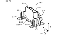
- FIG. 7 is a front perspective view of the measurement device mounting portion according to the first embodiment.
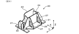
- FIG. 8 is a rear perspective view of the measurement device mounting portion according to the first embodiment.
- FIG. 9 is a top view of the measurement device mounting portion according to the first embodiment.
- FIG. 10 is a vertical cross-sectional view of the workpiece holding device according to the first embodiment with a reference block attached thereto.
- the gear measuring machine 1 of the first embodiment is incorporated in a processing line 100 as shown in FIG. 1.
- the processing line 100 includes a plurality of processing devices 101-103 and the gear measuring machine 1, and the gear measuring machine 1 is provided at the end position of a line L in the processing line 100.
- the direction of movement of the workpiece W in the processing line 100 is L.
- the gear measuring machine 1 may not be disposed at the end position in the processing line 100, but may be disposed at an intermediate position on the line L.
- the processing devices 101-103 are not particularly limited and may be known machine tools.
- the processing line 100 performs gear machining to process and mold the workpiece W, which is the object of processing, into the shape of a gear.
- the gear may be an internal gear or an external gear.
- the processing line 100 multiple processing devices 101 to 103 sequentially process the workpieces W, and the gear measuring machine 1 measures the workpieces W processed by the multiple processing devices 101 to 103. In this way, the processing line 100 continuously processes and measures the workpieces W, and also continuously produces multiple workpieces W.
- the processing line 100 is equipped with a transport device 104 that loads and unloads the workpiece W.
- the transport device 104 may be disposed at each of the processing devices 101-103 and the gear measuring machine 1, or may be disposed across multiple processing devices 101-103 and the gear measuring machine 1.
- the transport device 104 may be, for example, a serial robot type transport device, a loader type transport device, an automated guided vehicle (AGV), or the like.
- the gear measuring machine 1 includes a bed 10, a measuring device mounting section 20, a measuring device 30, a moving mechanism 40, a workpiece holding device 50, a cover 60, and a measurement result transmitting section 70.
- a transport device 104 for loading and unloading the workpiece W into and from the gear measuring machine 1 is provided near the gear measuring machine 1.
- the type of the gear measuring machine 1 is not limited, and it may be a vertical measuring machine that moves a probe vertically to perform measurements, or a horizontal measuring machine that moves a probe horizontally to perform measurements. In this embodiment, a vertical measuring machine is used as described later.
- the front-rear direction parallel to the line L is defined as X
- the vertical direction is defined as Z
- the width direction perpendicular to the X direction and the Z direction is defined as Y.
- the bed 10 constitutes the base of the gear measuring machine 1, has a substantially flat upper surface 11, and is provided with a plurality of legs 12 at the bottom.
- the shape of the bed 10 is not limited, but in this embodiment, the bed 10 is formed by combining metal sheets and is hollow. The hollow portion of the bed 10 may be filled with a filler.
- a recess 13 is formed by recessing the upper surface 11 in an area on the side of the processing device 103 adjacent to the gear measuring machine 1, and a workpiece holding device 50 (described later) is provided therein.
- the measuring device attachment part 20 is provided on the upper surface 11 of the bed 10.
- the measuring device attachment part 20 is also called a slider.
- the measuring device attachment part 20 is capable of reciprocating movement on the upper surface 11 of the bed 10 in the extension direction of the guide rails 41 (in this embodiment, a direction parallel to the line L) via a pair of guide rails 41 constituting a moving mechanism 40 described later.
- the method of determining the shape of the measuring device mounting part 20 is not limited, but in this embodiment, the shape is determined based on the optimized shape obtained by performing topology optimization processing based on the results of stress analysis of the measuring device mounting part 20 based on the elements that vary in the measuring device mounting part 20.
- the elements that vary in the measuring device mounting part 20 are not limited, and examples include temperature changes of the measuring device 30 attached to the measuring device mounting part 20 and the position of the load applied to the measuring device mounting part 20 that varies depending on the position state of the probe in the measuring device 30.
- the measuring device mounting section 20 includes a pair of bases 21 connected to the guide rail 41, and a plurality of side ribs 22 erected in the vertical direction Z on each of the pair of bases 21. Between the side ribs 22 facing each other in the width direction Y, a first central rib 23 and a second central rib 24 are provided, which extend in the width direction Y and the vertical direction Z.
- the first central rib 23 is located on the side (front side) of the processing device 103 adjacent to the gear measuring device 1, and the second central rib 24 is located on the opposite side.
- a flat surface 25 extending in the width direction Y and the front-rear direction X is provided at the lower vertical ends of the first central rib 23 and the second central rib 24.
- the measuring device 30 described later is fixed to the surface of the first central rib 23 on the side (front side) of the processing device 103 adjacent to the gear measuring device 1.
- a back rib 27 erected in the vertical direction Z from the flat surface 25 and extending in the front-rear direction X is connected to the back side of the second central rib 24.
- the end 251 of the planar portion 25 on the side (front side) of the processing device 103 adjacent to the gear measuring device 1 is curved in a wave-like shape with multiple continuous arcs, and has a first through hole 261 with a portion that follows the shape of the end 251 at a position inside (back side) the end 251.
- the planar portion 25 also has a second through hole 262 at a position on the back side of the first through hole 261. Note that a portion of the first central rib 23 overlaps with the first through hole 261 when viewed from above in the vertical direction Z.
- the measuring device 30 includes a probe 31, a probe holding section 32, a first slide base 33, a first guide section 34, a second slide base 35, and a second guide section 36.
- the first guide section 34 extends in the width direction Y
- the first slide base 33 is provided on the first guide section 34 and configured to be movable in the width direction Y.
- the second guide section 36 is provided on the first slide base 33 and extends in the vertical direction Z.
- the second slide base 35 is provided on the second guide section 36 and configured to be movable in the vertical direction Z.
- the probe 31 is substantially rod-shaped and is held by the probe holding section 32.
- the probe holding section 32 is provided on the second slide base 35.
- Moving mechanism 40 The moving mechanism 40 is configured to move the measuring device attachment portion 20 back and forth between a retracted position P1 shown in Fig. 2 and a measuring position P2 shown in Fig. 3.
- the moving mechanism 40 is configured to move the measuring device attachment portion 20 back and forth between a retracted position P1 shown in Fig. 2 and a measuring position P2 shown in Fig. 3.
- the measuring device includes a pair of guide rails 41 provided on the upper surface 11 of the bed 10, and a driving device 42.
- the pair of guide rails 41 are provided on the upper surface 11 of the bed 10 and extend in the front-rear direction X.
- the mounting portion 20 is movable in the front-rear direction X along a pair of guide rails 41 .
- the workpiece holding device 50 includes a workpiece holding section 51 that holds the workpiece W, and a rotation mechanism 52 that rotates the workpiece holding section 51 to a position of an arbitrary rotation angle.
- the workpiece holding section 51 has a plurality of engagement sections 511 that protrude in the vertical direction, and holds the workpiece W by pressing the engagement sections 511 radially outward against the inner cylindrical surface of the workpiece W that constitutes the external gear.
- a cylindrical space 512 with the rotation shaft 50a as its axis is formed inside the plurality of engagement sections 511.
- the workpiece holding section 51 is fixed to a rotation table 521 provided in the rotation mechanism 52.
- the rotation mechanism 52 rotates the disk-shaped rotation table 521 to rotate the workpiece holding section 51 to a position of an arbitrary rotation angle.
- the reference block 53 shown in FIG. 10 When calibrating the work holding device 50, the reference block 53 shown in FIG. 10 is used.
- the reference block 53 is substantially cylindrical, and as shown in FIG. 10, it can be attached to the rotating table 521 via a fixing screw 522 while inserted into the cylindrical space 512 of the work holding section 51.
- the central axis of the inner circumferential surface of the reference block 53 is positioned coaxially with the rotation axis of the rotating table 521.
- the reference block 53 is attached to the rotating table 521 via the cylindrical space 512, and the inner circumferential surface of the opening 531 at the upper end of the reference block 53 is measured with the probe 31, thereby calibrating the center of rotation of the rotating table 521.
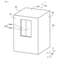
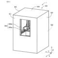
- Cover 60 As shown in Figures 4, 5 and 6, the cover 60 covers the bed 10, the measuring device mounting portion 20, the measuring device 30, the moving mechanism 40 and the workpiece holding device 50 all at once.
- the cover 60 is erected on the floor surface and includes a front wall portion 61, a rear wall portion 62, a right side wall portion 63, a left side wall portion 64 surrounding the above-mentioned components 10 to 50, and a ceiling portion 65 provided at the upper ends of the walls 61 to 64 to cover the upper portions.
- the front wall portion 61 is provided with an opening/closing portion 66.
- the configuration of the opening/closing portion 66 is not limited, in this embodiment, the right door 66a and the left door 66b are configured to move (slide) left and right to open and close. Note that, when the workpiece W is carried in and out from above the workpiece holding device 50, the opening/closing portion 66 may be provided on the ceiling portion 65 instead of the front wall portion 61.
- the opening/closing section 66 is configured to be opened when the workpiece W is attached to the workpiece holding device 50 and removed from the workpiece holding device 50, and to be closed when the workpiece W attached to the workpiece holding device 50 is measured by the measuring device 30.
- the opening and closing operation of the opening/closing section 66 is performed by a drive mechanism (not shown).
- Measurement result transmission unit 70 1 displays the measurement results by the measuring device 30 on a display screen (not shown) of the gear measuring machine 1, or transmits the results to a management device (not shown). Furthermore, the measurement result transmitting unit 70 transmits the measurement results by the measuring device 30 to at least one of the processing devices 101-103 included in the processing line 100.
- the processing devices 101-103 that receive the measurement results can adjust the processing conditions of the processing devices 101-103 in accordance with the measurement results.
- the measuring device mounting portion 20 is located at the retreat position P1 when the workpiece W is attached and detached, and is located at the measurement position P2 when the workpiece W held by the workpiece holding device 50 is measured, so that the conveying device 104 for attaching and detaching the workpiece W provided on the processing line L and the like are prevented from interfering with the measuring device 30. This makes it possible to automate the attachment and detachment of the workpiece W in the processing line L.
- the cover 60 is provided to collectively cover the bed 10, the measuring device 30, the measuring device mounting portion 20, the moving mechanism 40, and the workpiece holding device 50, and the cover 60 is provided with an opening/closing portion 66 that opens when the workpiece W is attached and detached and closes during measurement, thereby suppressing the intrusion of dust and oil mist generated on the processing line L into the gear measuring instrument 1, and preventing a decrease in measurement accuracy.
- the probe 31 is configured to come into contact with the workpiece W by moving vertically downward toward the workpiece W from above the workpiece W in the vertical direction Z when the measuring device mounting portion 20 is located at the measurement position P2.
- the gear measuring machine 1 is a so-called vertical measuring machine, and therefore it is easier to obtain high measurement accuracy compared to a horizontal measuring machine that measures by moving the probe horizontally.
- the probe tilts due to the effects of gravity, and accuracy is particularly poor at the front and rear ends or the left and right ends, but a vertical measuring machine is less susceptible to the effects of gravity and therefore has better accuracy than a horizontal measuring machine.
- the movement mechanism 40 includes a pair of guide rails 41 provided on the upper surface of the bed 10, and a drive device 42 that moves the measurement device mounting part 20 placed on the pair of guide rails 41 back and forth between the retracted position P1 and the measurement position P2 along the pair of guide rails 41. This allows the measurement device mounting part 20 to stably move back and forth between the retracted position P1 and the measurement position P2.
- the bed 10 has a recess 13 recessed downward in the vertical direction Z from the upper surface 11 of the bed 10 at a position vertically Z below the probe 31 when the measuring device mounting part 20 is located at the measurement position P2.
- the work holding device 50 is provided in the recess 13 and has a rotation mechanism 52 that rotates the held work W around an axis in the vertical direction Z. This makes it possible to prevent interference between the transport device 104 and the measuring device 30 when the transport device 104 attaches and detaches the work W to and from the work holding device 50 simply by moving the measuring device mounting part 20 to the retracted position P1, and makes it easy to switch between the retracted position P1 and the measurement position P2.
- the recess 13 is located below the probe 31 in the vertical direction Z when the measuring device mounting part 20 is located at the measurement position P2, and is located between the pair of guide rails 41. This allows the probe 31 to be positioned above the workpiece W in the vertical direction Z with the measuring device 30 being sufficiently supported via the pair of guide rails 41 and the measuring device mounting part 20, improving measurement accuracy.
- the measuring device mounting part 20 is stress analyzed based on the fluctuating factors in the measuring device mounting part 20. Then, topology optimization processing is performed based on the results of the stress analysis.
- the measuring device mounting part 20 has a shape determined based on the optimized shape obtained by the topology optimization processing. This makes it possible to optimize the shape of the measuring device mounting part 20, which has fluctuating factors, with higher precision. For example, one of the fluctuating factors is a change in room temperature inside the factory in which the gear measuring instrument 1 is installed. Since the shape of the measuring device mounting part 20 has a shape determined based on the optimized shape, it is possible to ensure the measurement precision of the gear measuring instrument 1 even if the room temperature inside the factory changes.
- the measuring device mounting part 20 has an end 251 on the front side (workpiece holding device 50 side) of the flat part 25 located vertically Z below the part (first central rib 23) where the measuring device 30 is mounted, which is curved in a wavy shape with multiple arcs continuously, and has a through hole 261 located more inward than the end 251 and having a portion that follows the shape of the end 251. This ensures the rigidity of the measuring device mounting part 20 while reducing its weight.
- the work holding device 50 has a cylindrical space 512 that opens vertically upward on the rotation axis of the work W, and the cylindrical space 512 is configured to allow a reference block 53 to be placed therein for performing positional calibration of the rotation axis 50a of the work W in the work holding device 50.
- the reference block 53 is made of a cylindrical member that is inserted into the cylindrical space 512 and fixed to a rotating table 521, which is a rotating part provided in the work holding device 50, and is configured so that the probe 31 comes into contact with the inner surface of the reference block 53 when performing positional calibration of the rotation axis 50a of the work W. This allows the positional calibration of the rotation axis 50a of the work W to be performed with high accuracy.
- the position of the rotating shaft 50a can be maintained even in a processing line 100 where temperature changes are likely to occur, and the measurement accuracy of the measuring device 30 can be maintained.
- a measurement result transmission unit 70 that transmits the measurement results by the measuring device 30 to at least one of the processing devices 101 to 103 included in the processing line 100. This allows the measurement results by the measuring device 30 to be fed back to the processing devices 101 to 103, thereby improving the processing accuracy of the processing devices 101 to 103.
- a mechanism constituting a tailstock can be used as the workpiece holding device 50 to measure gears formed on a shaft-shaped workpiece W.
- a gear measuring machine that can be installed on a processing line, can automate the attachment and detachment of workpieces, and can improve measurement accuracy.
Landscapes
- Physics & Mathematics (AREA)
- General Physics & Mathematics (AREA)
- Testing Of Devices, Machine Parts, Or Other Structures Thereof (AREA)
Abstract
ワーク(W)に歯車加工を施すための加工ライン(100)内に設けられる歯車測定機(1)であって、ワークを着脱可能に保持するワーク保持装置(50)と、ワークに接触させたプローブ(31)の変位を検出してワークを測定する測定装置(30)と、測定装置が取り付けられた測定装置取付部(20)と、測定装置取付部を支持するベッド(10)と、上記構成を一括して覆うカバー(60)と、を備える。カバーは、ワークをワーク保持装置へ取り付ける際及びワーク保持装置から取り外す際に開放し、ワークを測定装置により測定する際に閉塞する開閉部(66)を有している。ベッドには測定装置取付部を退避位置(P1)と測定位置(P2)との間を往復させる移動機構(40)を有している。移動機構は、ワークをワーク保持装置に保持させる際に測定装置取付部を退避位置に移動させ、ワークを測定する際に測定装置取付部を測定位置に移動させる。
Description
本発明は、歯車測定機に関する。
従来、ワークに形成された歯車を測定する歯車測定機が種々提案されている。例えば、特許文献1には、歯車加工機に歯車測定機能を持たせた構成が開示されている。また、特許文献2には、加工ラインに歯車測定機を組み込んでインライン検査を行う構成が開示されている。
しかしながら、特許文献1及び特許文献2に開示の構成では、歯車加工機や加工ラインにおいてワークの歯車加工により発生する粉塵やオイルミストが歯車測定機に影響して測定精度を低下させることについて何ら考慮されていない。そのため、通常は、歯車測定機は、歯車加工機とは別体で構成するとともに、加工ライン外にあって加工ラインで生じる粉塵やオイルミストの影響を受けない測定室に設置することが行われている。この場合は加工済みのワークを測定室に手動で搬入して歯車測定機に設置することにより測定を行う必要があるために手間がかかる。
また、測定室に設置される従来の歯車測定機ではワークの着脱を自動化することが考慮されていないため、このような歯車測定機にワークの着脱を自動化するための搬送装置などを設けると、搬送装置が歯車測定機の測定部と干渉するおそれがある。
本開示は、このような事情に鑑みてなされたものであり、加工ラインに設けられ、ワークの着脱を自動化できるとともに測定精度を向上することができる歯車測定機を提供しようとするものである。
本開示の一態様は、ワークに歯車加工を施すための加工ライン内に設けられる歯車測定機であって、
上記ワークを着脱可能に保持するワーク保持装置と、
上記ワークに接触させたプローブの変位を検出して上記ワークを測定する測定装置と、
上記測定装置が取り付けられた測定装置取付部と、
上記測定装置取付部を支持するベッドと、
上記ワーク保持装置、上記測定装置、上記測定装置取付部及び上記ベッドを一括して覆うカバーと、を備え、
上記カバーは、上記ワークを上記ワーク保持装置へ取り付ける際及び上記ワーク保持装置から取り外す際に開放し、上記ワーク保持装置に取り付けられた上記ワークを上記測定装置により測定する際に閉塞するように構成された開閉部を有しており、
上記ベッドには、上記測定装置取付部を、上記ワーク保持装置から離間した退避位置と、上記ワーク保持装置に近接した測定位置との間を往復させる移動機構を有しており、
上記移動機構は、上記ワークを上記ワーク保持装置に保持させる際に上記測定装置取付部を上記退避位置に移動させ、上記ワーク保持装置に保持された上記ワークを測定する際に上記測定装置取付部を上記測定位置に移動させるように構成されている、歯車測定機にある。
上記態様の歯車測定機によれば、測定装置取付部は、ワークの取り付け及び取り外しの際には退避位置に位置し、ワーク保持装置に保持されたワークの測定の際には測定位置に位置するため、加工ラインに設けられたワークの取り付け及び取り外しのための搬送装置などが測定装置と干渉することが防止される。これにより、加工ライン内においてワークの取り付け及び取り外しの自動化を図ることができる。また、ワーク保持装置、測定装置、測定装置取付部及びベッドを一括して覆うカバーを備え、カバーにはワークの取り付け及び取り外しの際に開放し、測定時には閉塞する開閉部が設けられていることにより、加工ラインで発生する粉塵やオイルミストが歯車測定機内に侵入することが抑制され、測定精度の低下を防止できる。
以上のごとく、上記一態様によれば、加工ラインに設けられ、ワークの着脱を自動化できるとともに測定精度を向上することができる歯車測定機を提供することができる。
(実施形態1)
1.加工ライン100
本実施形態1の歯車測定機1は、図1に示すように、加工ライン100に組み込まれている。本実施形態では、加工ライン100には複数の加工装置101~103と歯車測定機1が含まれており、歯車測定機1は加工ライン100におけるラインLの最終位置に設けられている。本実施形態では、加工ライン100におけるワークWの移送方向をLとする。なお、加工ライン100における歯車測定機1の配置は最終位置でなく、ラインLの途中位置にあってもよい。加工装置101~103は特に限定されず、公知の工作機械とすることができる。加工ライン100は加工対象であるワークWを歯車の形状に加工成形する歯車加工を施す。歯車は、内歯車でも外歯車でもよい。
加工ライン100において、複数の加工装置101~103がワークWに対する加工を順次行い、歯車測定機1が複数の加工装置101~103により加工されたワークWの測定を行う。このようにして、加工ライン100は、ワークWの加工及び測定を連続して行うと共に、複数のワークWの連続生産を行う。
連続生産を実現するために、加工ライン100は、ワークWの搬入、搬出を行う搬送装置104を備える。搬送装置104は、各加工装置101~103及び歯車測定機1のそれぞれに配置しても良いし、複数の加工装置101~103及び歯車測定機1に跨って配置しても良い。搬送装置104は、例えば、シリアルロボット型搬送装置、ローダ型搬送装置、無人搬送車(AGV)などを適用できる。
2.歯車測定機1の構成
図2に示すように、歯車測定機1は、ベッド10、測定装置取付部20、測定装置30、移動機構40、ワーク保持装置50、カバー60、測定結果送信部70を備える。また、歯車測定機1の近傍には、歯車測定機1へのワークWの搬入と搬出を行う搬送装置104が設けられている。歯車測定機1の種類は限定されず、プローブを鉛直方向に移動させて測定する立形測定機や、プローブを水平方向に移動させて測定する横形測定機とすることができ、本実施形態では、後述するように立形測定機を採用している。歯車測定機1において、ラインLに平行な前後方向をX、鉛直方向をZ、X方向とZ方向に直交する幅方向をYとする。
図2に示すように、歯車測定機1は、ベッド10、測定装置取付部20、測定装置30、移動機構40、ワーク保持装置50、カバー60、測定結果送信部70を備える。また、歯車測定機1の近傍には、歯車測定機1へのワークWの搬入と搬出を行う搬送装置104が設けられている。歯車測定機1の種類は限定されず、プローブを鉛直方向に移動させて測定する立形測定機や、プローブを水平方向に移動させて測定する横形測定機とすることができ、本実施形態では、後述するように立形測定機を採用している。歯車測定機1において、ラインLに平行な前後方向をX、鉛直方向をZ、X方向とZ方向に直交する幅方向をYとする。
2-1.ベッド10
ベッド10は歯車測定機1の基部を構成するものであって、上面11は略平面状となっており、下部に複数の脚部12を備える。ベッド10の形態は限定されないが、本実施形態では、板金を組み合わせて構成され、中空となっている。なお、ベッド10の中空部に充填物が充填されていてもよい。ベッド10において、歯車測定機1と隣り合う加工装置103側の領域には上面11が凹んだ凹部13が形成されており、後述するワーク保持装置50が設けられている。
ベッド10は歯車測定機1の基部を構成するものであって、上面11は略平面状となっており、下部に複数の脚部12を備える。ベッド10の形態は限定されないが、本実施形態では、板金を組み合わせて構成され、中空となっている。なお、ベッド10の中空部に充填物が充填されていてもよい。ベッド10において、歯車測定機1と隣り合う加工装置103側の領域には上面11が凹んだ凹部13が形成されており、後述するワーク保持装置50が設けられている。
2-2.測定装置取付部20
測定装置取付部20は、ベッド10の上面11に設けられている。なお、測定装置取付部20はスライダーともいう。測定装置取付部20は後述する移動機構40を構成する一対のガイドレール41を介してベッド10の上面11にガイドレール41の延在方向(本実施形態ではラインLに平行な方向)に往復移動可能となっている。
測定装置取付部20は、ベッド10の上面11に設けられている。なお、測定装置取付部20はスライダーともいう。測定装置取付部20は後述する移動機構40を構成する一対のガイドレール41を介してベッド10の上面11にガイドレール41の延在方向(本実施形態ではラインLに平行な方向)に往復移動可能となっている。
測定装置取付部20の形状の決定方法は限定されないが、本実施形態では、測定装置取付部20において変動する要素に基づいて測定装置取付部20を応力解析した結果に基づいてトポロジー最適化処理を行って得られた最適化形状に基づいて決定した。測定装置取付部20において変動する要素は限定されず、測定装置取付部20に取り付けられる測定装置30の温度変化や、測定装置30におけるプローブの位置状態に応じて変動する測定装置取付部20にかかる荷重の位置などを例示できる。本実施形態では測定装置取付部20において変動する要素として、測定装置30の温度変化を採用し、応力解析とトポロジー最適化処理を行って最適化形状を算出し、当該最適化形状に基づいて、図7~9に示す測定装置取付部20の形状を決定した。これらにより、工場内部の室温が変化しても測定精度が確保できる機械構成(構造)となっている。
図7~9に示すように、測定装置取付部20は、ガイドレール41に接続される一対の基部21と、一対の基部21にそれぞれ鉛直方向Zに立設された複数の横側リブ22を備える。幅方向Yに対向する横側リブ22の間には、幅方向Y及び鉛直方向Zに広がる第1中央リブ23、第2中央リブ24が設けられている。第1中央リブ23は歯車測定機1と隣り合う加工装置103側(正面側)に位置し、第2中央リブ24は反対側に位置する。第1中央リブ23及び第2中央リブ24の鉛直方向下端には、幅方向Y及び前後方向Xに広がる平面部25が設けられている。第1中央リブ23における歯車測定機1と隣り合う加工装置103側(正面側)の面には、後述する測定装置30が固定される。第2中央リブ24の背面側には平面部25から鉛直方向Zに立設されて前後方向Xに延在する背面リブ27が接続されている。
図9に示すように、平面部25における歯車測定機1と隣り合う加工装置103側(正面側)の端部251は複数の円弧が連続して波状に湾曲しているとともに、該端部251よりも内側(背面側)の位置に端部251の形状に沿う部分を有する第1貫通孔261を有している。また、平面部25は、第1貫通孔261の背面側の位置に第2貫通孔262を有している。なお、第1中央リブ23の一部は、鉛直方向Z上方から見て第1貫通孔261と重なっている。
2-3.測定装置30
図4に示すように、測定装置30は、プローブ31、プローブ保持部32、第1スライドベース33、第1案内部34、第2スライドベース35、第2案内部36を備える。第1案内部34は幅方向Yに延在し、第1スライドベース33は第1案内部34に設けられて幅方向Yに移動可能に構成されている。第2案内部36は、第1スライドベース33に設けられるとともに鉛直方向Zに延在する。第2スライドベース35は、第2案内部36に設けられて鉛直方向Zに移動可能に構成されている。プローブ31は略棒状をなしており、プローブ保持部32に保持される。プローブ保持部32は第2スライドベース35に設けられる。
図4に示すように、測定装置30は、プローブ31、プローブ保持部32、第1スライドベース33、第1案内部34、第2スライドベース35、第2案内部36を備える。第1案内部34は幅方向Yに延在し、第1スライドベース33は第1案内部34に設けられて幅方向Yに移動可能に構成されている。第2案内部36は、第1スライドベース33に設けられるとともに鉛直方向Zに延在する。第2スライドベース35は、第2案内部36に設けられて鉛直方向Zに移動可能に構成されている。プローブ31は略棒状をなしており、プローブ保持部32に保持される。プローブ保持部32は第2スライドベース35に設けられる。
第1案内部34及び第2案内部36の駆動は図示しない駆動装置により行われ、第1案内部34及び第2案内部36の駆動により、プローブ31の幅方向Y及び鉛直方向Zの位置決めがなされる。なお、前後方向Xの位置決めは、後述する移動機構40により行われる。プローブ31には位置決め後のプローブ31の変位を検出する変位検出装置(図示せず)が接続されている。そして、測定装置30は、プローブ31を前後方向X、幅方向Y又は鉛直方向ZからワークW(歯車)の歯溝などに接触させることにより、ワークWのOBD(Over Ball(Pin) Diameter)やBBD(Between Ball Diameter)などを測定する。
2-4.移動機構40
移動機構40は、測定装置取付部20を、図2に示す退避位置P1と図3に示す測定位置P2との間を往復移動するように構成されている。移動機構40は、図4に示すベッド10の上面11に設けられた一対のガイドレール41と、駆動装置42とを含む。一対のガイドレール41はベッド10の上面11に設けられて前後方向Xに延在している。測定装置取付部20は一対のガイドレール41に沿って、前後方向Xに移動可能となっている。
移動機構40は、測定装置取付部20を、図2に示す退避位置P1と図3に示す測定位置P2との間を往復移動するように構成されている。移動機構40は、図4に示すベッド10の上面11に設けられた一対のガイドレール41と、駆動装置42とを含む。一対のガイドレール41はベッド10の上面11に設けられて前後方向Xに延在している。測定装置取付部20は一対のガイドレール41に沿って、前後方向Xに移動可能となっている。
図3に示すように、測定位置P2は、測定装置取付部20が後述するワーク保持装置50に近接する位置である。測定装置取付部20が測定位置P2にあるとき、測定装置30によりワークWの測定を行う。図2に示すように、退避位置P1は、測定装置取付部20がワーク保持装置50から離間する位置である。測定装置取付部20が退避位置P1にあるとき、ワーク保持装置50の鉛直方向上方の領域Rから測定装置取付部20が退避するため、領域Rにおいて搬送装置104によりワークWの搬入及び搬出を行う際に搬送装置104と測定装置30とが干渉することが防止される。
2-5.ワーク保持装置50
ワーク保持装置50は、ワークWを保持するワーク保持部51と、ワーク保持部51を任意の回転角の位置に回転させる回転機構52とを含む。本実施形態では、図10に示すように、ワーク保持部51は鉛直方向に突出した複数の係合部511を有し、該係合部511を外歯車を構成するワークWの内側円筒面に径方向外方に押し当てることによりワークWを保持する。複数の係合部511の内側には、回転軸50aを軸心とする円柱状空間512が形成されている。ワーク保持部51は回転機構52に備えられた回転テーブル521に固定されている。回転機構52は、円盤状の回転テーブル521を回転駆動することによりワーク保持部51を任意の回転角の位置に回転させる。
ワーク保持装置50は、ワークWを保持するワーク保持部51と、ワーク保持部51を任意の回転角の位置に回転させる回転機構52とを含む。本実施形態では、図10に示すように、ワーク保持部51は鉛直方向に突出した複数の係合部511を有し、該係合部511を外歯車を構成するワークWの内側円筒面に径方向外方に押し当てることによりワークWを保持する。複数の係合部511の内側には、回転軸50aを軸心とする円柱状空間512が形成されている。ワーク保持部51は回転機構52に備えられた回転テーブル521に固定されている。回転機構52は、円盤状の回転テーブル521を回転駆動することによりワーク保持部51を任意の回転角の位置に回転させる。
ワーク保持装置50は、ワーク保持装置50の校正を行う際に、図10に示す基準ブロック53を用いる。基準ブロック53は略円筒状をなしており、図10に示すように、ワーク保持部51の円柱状空間512に挿入した状態で固定ねじ522を介して回転テーブル521に取り付け可能となっている。基準ブロック53の内周面の中心軸は、回転テーブル521の回転軸と同軸上に位置する。ワーク保持装置50の校正を行う際には、円柱状空間512を介して基準ブロック53を回転テーブル521に取り付けて基準ブロック53の上端の開口部531の内周面をプローブ31で測定することで回転テーブル521の回転中心の校正を行うことができる。
2-6.カバー60
図4、図5及び図6に示すように、カバー60は、ベッド10、測定装置取付部20、測定装置30、移動機構40及びワーク保持装置50を一括して覆う。カバー60は、床面に立設されて、上記構成10~50の周囲を囲む正面壁部61、背面壁部62、右側面壁部63、左側面壁部64と各壁部61~64の上端に設けられて上方を覆う天井部65を含む。また、図5及び図6に示すように、正面壁部61には開閉部66が設けられている。開閉部66の構成は限定されないが、本実施形態では、右側扉66aと左側扉66bとが左右に移動(スライド)して開閉する構成としている。なお、ワーク保持装置50の上方からワークWの搬入出を行う場合には、開閉部66は、正面壁部61に代えて、天井部65に設けると良い。
図4、図5及び図6に示すように、カバー60は、ベッド10、測定装置取付部20、測定装置30、移動機構40及びワーク保持装置50を一括して覆う。カバー60は、床面に立設されて、上記構成10~50の周囲を囲む正面壁部61、背面壁部62、右側面壁部63、左側面壁部64と各壁部61~64の上端に設けられて上方を覆う天井部65を含む。また、図5及び図6に示すように、正面壁部61には開閉部66が設けられている。開閉部66の構成は限定されないが、本実施形態では、右側扉66aと左側扉66bとが左右に移動(スライド)して開閉する構成としている。なお、ワーク保持装置50の上方からワークWの搬入出を行う場合には、開閉部66は、正面壁部61に代えて、天井部65に設けると良い。
開閉部66は、図2に示すようにワークWをワーク保持装置50へ取り付ける際及びワーク保持装置50から取り外す際に開放し、ワーク保持装置50に取り付けられたワークWを測定装置30により測定する際に閉塞するように構成されている。なお、開閉部66の開閉動作は、図示しない駆動機構により行われる。
2-7.測定結果送信部70
図1に示す測定結果送信部70は、測定装置30による測定結果を、歯車測定機1における図示しない表示画面に表示したり、図示しない管理装置に送信したりする。さらに、測定結果送信部70は、測定装置30による測定結果を、加工ライン100に含まれる少なくとも一つの加工装置101~103に送信する。測定結果を受信した加工装置101~103は、当該測定結果に応じて、加工装置101~103における加工条件の調整を行うことができる。
図1に示す測定結果送信部70は、測定装置30による測定結果を、歯車測定機1における図示しない表示画面に表示したり、図示しない管理装置に送信したりする。さらに、測定結果送信部70は、測定装置30による測定結果を、加工ライン100に含まれる少なくとも一つの加工装置101~103に送信する。測定結果を受信した加工装置101~103は、当該測定結果に応じて、加工装置101~103における加工条件の調整を行うことができる。
3.作用効果
本実施態様の歯車測定機1によれば、測定装置取付部20は、ワークWの取り付け及び取り外しの際には退避位置P1に位置し、ワーク保持装置50に保持されたワークWの測定の際には測定位置P2に位置するため、加工ラインLに設けられたワークWの取り付け及び取り外しのための搬送装置104などが測定装置30と干渉することが防止される。これにより、加工ラインL内においてワークWの取り付け及び取り外しの自動化を図ることができる。また、ベッド10、測定装置30、測定装置取付部20、移動機構40及びワーク保持装置50を一括して覆うカバー60を備え、カバー60にはワークWの取り付け及び取り外しの際に開放し、測定時には閉塞する開閉部66が設けられていることにより、加工ラインLで発生する粉塵やオイルミストが歯車測定機1内に侵入することが抑制され、測定精度の低下を防止できる。
本実施態様の歯車測定機1によれば、測定装置取付部20は、ワークWの取り付け及び取り外しの際には退避位置P1に位置し、ワーク保持装置50に保持されたワークWの測定の際には測定位置P2に位置するため、加工ラインLに設けられたワークWの取り付け及び取り外しのための搬送装置104などが測定装置30と干渉することが防止される。これにより、加工ラインL内においてワークWの取り付け及び取り外しの自動化を図ることができる。また、ベッド10、測定装置30、測定装置取付部20、移動機構40及びワーク保持装置50を一括して覆うカバー60を備え、カバー60にはワークWの取り付け及び取り外しの際に開放し、測定時には閉塞する開閉部66が設けられていることにより、加工ラインLで発生する粉塵やオイルミストが歯車測定機1内に侵入することが抑制され、測定精度の低下を防止できる。
また、本実施形態1では、プローブ31は、測定装置取付部20が測定位置P2に位置するときにワークWの鉛直方向Z上方からワークWに向けて鉛直方向下方に移動することにより、ワークWに接触するように構成されている。これにより、歯車測定機1はいわゆる立形測定機であるため、プローブを水平方向に移動させて測定する横形測定機である場合に比べて、高い測定精度が得られやすい。また、横形測定機はプローブが重力の影響を受けて傾くため、特に前後端または左右端において精度が悪くなるが、立形測定機は重力の影響を受けにくいいため、横形測定機に比べて精度が良い。
また、本実施形態1では、移動機構40は、ベッド10の上面に設けられた一対のガイドレール41と、該一対のガイドレール41上に載置された測定装置取付部20を一対のガイドレール41に沿って退避位置P1と測定位置P2との間を往復移動させる駆動装置42とを含む。これにより、測定装置取付部20を退避位置P1と測定位置P2との間の往復移動を安定して行うことができる。
また、本実施形態1では、ベッド10は、測定装置取付部20が測定位置P2に位置するときのプローブ31の鉛直方向Z下方の位置に、ベッド10の上面11から鉛直方向Z下方に凹んだ凹部13を有している。そして、ワーク保持装置50は、凹部13に設けられているとともに、保持したワークWを鉛直方向Zを軸として回転させる回転機構52を有している。これにより、測定装置取付部20を退避位置P1に移動させるだけで、搬送装置104によるワークWのワーク保持装置50への取り付けと取り外しの際に搬送装置104と測定装置30とが干渉しないようにでき、容易に退避位置P1と測定位置P2との切り替えが容易となる。
また、本実施形態1では、凹部13は、測定装置取付部20が測定位置P2に位置するときのプローブ31の鉛直方向Z下方の位置であって、一対のガイドレール41の間の位置に位置している。これにより、一対のガイドレール41及び測定装置取付部20を介して測定装置30が十分に支持された状態で、プローブ31をワークWの鉛直方向Z上方に位置させることができ、測定精度を向上させることができる。
また、本実施形態1では、測定装置取付部20において変動する要素に基づいて測定装置取付部20を応力解析している。そして、応力解析の結果に基づいてトポロジー最適化処理を行っている。測定装置取付部20は、トポロジー最適化処理で得られた最適化形状に基づいて決定された形状を有している。これにより、変動する要素を有する測定装置取付部20の形状をより高精度に最適化することができる。例えば、変動する要素として歯車測定機1が設置された工場内部の室温の変化があげられるが、測定装置取付部20の形状が上記最適化形状に基づいて決定された形状を有していることにより、当該工場内部の室温が変化しても歯車測定機1による測定精度を確保することができる。
また、本実施形態1では、測定装置取付部20は、測定装置30が取り付けられる部位(第1中央リブ23)の鉛直方向Z下方に位置する平面部25の正面側(ワーク保持装置50側)の端部251は複数の円弧が連続して波状に湾曲しているとともに、該端部251よりも内側の位置に端部251の形状に沿う部分を有する貫通孔261を有している。これにより、測定装置取付部20の剛性を担保しつつ軽量化が図れている。
また、本実施形態1では、ワーク保持装置50は、ワークWの回転軸上に鉛直方向上方に開口した円柱状空間512を有しており、円柱状空間512には、ワーク保持装置50におけるワークWの回転軸50aの位置校正を行うための基準ブロック53が配設可能に構成されている。そして、基準ブロック53は円柱状空間512に挿入されるとともにワーク保持装置50に備えられた回転部である回転テーブル521に固定される円筒部材からなり、ワークWの回転軸50aの位置校正をする際には、プローブ31は基準ブロック53の内周面に接触させるように構成されている。これにより、ワークWの回転軸50aの位置校正を高精度に行うことができる。
そして、当該基準ブロック53による回転軸50aの位置校正を随時行うことで、温度変化の生じやすい加工ライン100であっても、回転軸50aの位置を維持することができ、測定装置30の測定精度を維持することができる。
また、本実施形態1では、測定装置30による測定結果を、加工ライン100に含まれる少なくとも一つの加工装置101~103に送信する測定結果送信部70を有している。これにより、測定装置30による測定結果を加工装置101~103にフィードバックすることができ、加工装置101~103による加工精度の向上を図ることができる。
なお、本実施形態では、ワーク保持装置50として、心押し台を構成する機構を適用することで、シャフト形状のワークWに形成された歯車の測定を行うこともできる。
以上のごとく、上記一態様によれば、加工ラインに設けられ、ワークの着脱を自動化できるとともに測定精度を向上することができる歯車測定機を提供することができる。
Claims (9)
- ワークに歯車加工を施すための加工ライン内に設けられる歯車測定機であって、
上記ワークを着脱可能に保持するワーク保持装置と、
上記ワークに接触させたプローブの変位を検出して上記ワークを測定する測定装置と、
上記測定装置が取り付けられた測定装置取付部と、
上記測定装置取付部を支持するベッドと、
上記ワーク保持装置、上記測定装置、上記測定装置取付部及び上記ベッドを一括して覆うカバーと、を備え、
上記カバーは、上記ワークを上記ワーク保持装置へ取り付ける際及び上記ワーク保持装置から取り外す際に開放し、上記ワーク保持装置に取り付けられた上記ワークを上記測定装置により測定する際に閉塞するように構成された開閉部を有しており、
上記ベッドには、上記測定装置取付部を、上記ワーク保持装置から離間した退避位置と、上記ワーク保持装置に近接した測定位置との間を往復させる移動機構を有しており、
上記移動機構は、上記ワークを上記ワーク保持装置に保持させる際に上記測定装置取付部を上記退避位置に移動させ、上記ワーク保持装置に保持された上記ワークを測定する際に上記測定装置取付部を上記測定位置に移動させるように構成されている、歯車測定機。 - 上記プローブは、上記測定装置取付部が上記測定位置に位置するときに上記ワークの鉛直方向上方から上記ワークに向けて鉛直方向下方に移動することにより、上記ワークに接触するように構成されている、請求項1に記載の歯車測定機。
- 上記移動機構は、上記ベッドの上面に設けられた一対のガイドレールと、該一対のガイドレール上に載置された上記測定装置取付部を上記一対のガイドレールに沿って上記測定位置と上記退避位置との間を往復移動させる駆動装置とを含む、請求項1又は2に記載の歯車測定機。
- 上記ベッドは、上記測定装置取付部が上記測定位置に位置するときの上記プローブの鉛直方向下方の位置に、上記ベッドの上面から鉛直方向下方に凹んだ凹部を有しており、
上記ワーク保持装置は、上記凹部に設けられているとともに、保持した上記ワークを鉛直方向を軸として回転させる回転機構を有している、請求項1又は2に記載の歯車測定機。 - 上記ベッドは、上記測定装置取付部が上記測定位置に位置するときの上記プローブの鉛直方向下方の位置であって、上記一対のガイドレールの間の位置に、上記ベッドの上面から鉛直方向下方に凹んだ凹部を有しており、
上記ワーク保持装置は、上記凹部に設けられているとともに、保持した上記ワークを鉛直方向を軸として回転させる回転機構を有している、請求項3に記載の歯車測定機。 - 上記測定装置取付部は、上記測定装置取付部において変動する要素に基づいて上記測定装置取付部を応力解析した結果に基づいてトポロジー最適化処理を行って得られた最適化形状に基づいて決定された形状を有している、請求項1又は2に記載の歯車測定機。
- 上記測定装置取付部は、上記測定装置が取り付けられる部位の鉛直方向下方に位置する平面部における上記ワーク保持装置側の端部は複数の円弧が連続して波状に湾曲しているとともに、該端部よりも内側の位置に上記端部の形状に沿う部分を有する貫通孔を有している、請求項5に記載の歯車測定機。
- 上記ワーク保持装置は、上記ワークの回転軸上に鉛直方向上方に開口した円柱状空間を有しており、
上記円柱状空間には、上記ワーク保持装置における上記ワークの回転軸の位置校正を行うための基準ブロックが配設可能に構成されており、
上記基準ブロックは、上記円柱状空間に挿入されるとともに上記ワーク保持装置に備えられた回転部に固定される円筒部材からなり、上記ワークの回転軸の上記位置校正をする際には、上記プローブは上記円筒部材の内周面に接触させるように構成されている、請求項1又は2に記載の歯車測定機。 - 上記測定装置による測定結果を、上記加工ラインに含まれる少なくとも一つの加工装置に送信する測定結果送信部を有している、請求項1又は2に記載の歯車測定機。
Priority Applications (2)
| Application Number | Priority Date | Filing Date | Title |
|---|---|---|---|
| JP2025525519A JPWO2024252551A1 (ja) | 2023-06-07 | 2023-06-07 | |
| PCT/JP2023/021139 WO2024252551A1 (ja) | 2023-06-07 | 2023-06-07 | 歯車測定機 |
Applications Claiming Priority (1)
| Application Number | Priority Date | Filing Date | Title |
|---|---|---|---|
| PCT/JP2023/021139 WO2024252551A1 (ja) | 2023-06-07 | 2023-06-07 | 歯車測定機 |
Publications (1)
| Publication Number | Publication Date |
|---|---|
| WO2024252551A1 true WO2024252551A1 (ja) | 2024-12-12 |
Family
ID=93795591
Family Applications (1)
| Application Number | Title | Priority Date | Filing Date |
|---|---|---|---|
| PCT/JP2023/021139 Ceased WO2024252551A1 (ja) | 2023-06-07 | 2023-06-07 | 歯車測定機 |
Country Status (2)
| Country | Link |
|---|---|
| JP (1) | JPWO2024252551A1 (ja) |
| WO (1) | WO2024252551A1 (ja) |
Citations (6)
| Publication number | Priority date | Publication date | Assignee | Title |
|---|---|---|---|---|
| JPH0634489A (ja) * | 1992-07-14 | 1994-02-08 | Osaka Seimitsu Kikai Kk | ボールマスターギア |
| JPH0814809A (ja) * | 1994-06-29 | 1996-01-19 | Kawasaki Steel Corp | 薄板の表面粗さ測定装置及び方法 |
| JP2005121556A (ja) * | 2003-10-20 | 2005-05-12 | Mitsutoyo Corp | ワーク曲面の測定方法とそのプログラムおよび媒体 |
| CN110889166A (zh) * | 2019-10-30 | 2020-03-17 | 南京理工大学 | 基于热力耦合约束的航空用轴承支架轻量化设计方法 |
| JP2021148770A (ja) * | 2020-03-17 | 2021-09-27 | 株式会社東京精密 | 内面形状測定機の倍率校正方法、及び内面形状測定機 |
| JP2022066416A (ja) * | 2018-03-02 | 2022-04-28 | 株式会社東京精密 | 形状測定装置 |
Family Cites Families (8)
| Publication number | Priority date | Publication date | Assignee | Title |
|---|---|---|---|---|
| JP3132128B2 (ja) * | 1992-03-31 | 2001-02-05 | スズキ株式会社 | ワークの加工装置 |
| JP3072693B2 (ja) * | 1993-06-25 | 2000-07-31 | トヨタ自動車株式会社 | 歯車形状の測定方法 |
| JP3272952B2 (ja) * | 1996-07-02 | 2002-04-08 | キヤノン株式会社 | 3次元形状測定装置 |
| DE102004017172A1 (de) * | 2004-04-02 | 2005-10-20 | Jan Bernd Lugtenburg | Verfahren und Vorrichtung zur Vermessung eines Messobjekts |
| JP5277033B2 (ja) * | 2009-03-25 | 2013-08-28 | 株式会社ミツトヨ | 補正ボール径算出方法および形状測定装置 |
| JP5971902B2 (ja) * | 2011-06-28 | 2016-08-17 | キヤノン株式会社 | ワーク保持装置及び、このワーク保持装置を備えた3次元形状測定装置 |
| JP6001701B2 (ja) * | 2015-01-23 | 2016-10-05 | ファナック株式会社 | ワークに対して作業を即時に行うことが可能なシステム |
| JP7090365B1 (ja) * | 2021-07-30 | 2022-06-24 | 有限会社ピーシー・テクニクス | クランプ装置、固定治具、三次元測定機 |
-
2023
- 2023-06-07 WO PCT/JP2023/021139 patent/WO2024252551A1/ja not_active Ceased
- 2023-06-07 JP JP2025525519A patent/JPWO2024252551A1/ja active Pending
Patent Citations (6)
| Publication number | Priority date | Publication date | Assignee | Title |
|---|---|---|---|---|
| JPH0634489A (ja) * | 1992-07-14 | 1994-02-08 | Osaka Seimitsu Kikai Kk | ボールマスターギア |
| JPH0814809A (ja) * | 1994-06-29 | 1996-01-19 | Kawasaki Steel Corp | 薄板の表面粗さ測定装置及び方法 |
| JP2005121556A (ja) * | 2003-10-20 | 2005-05-12 | Mitsutoyo Corp | ワーク曲面の測定方法とそのプログラムおよび媒体 |
| JP2022066416A (ja) * | 2018-03-02 | 2022-04-28 | 株式会社東京精密 | 形状測定装置 |
| CN110889166A (zh) * | 2019-10-30 | 2020-03-17 | 南京理工大学 | 基于热力耦合约束的航空用轴承支架轻量化设计方法 |
| JP2021148770A (ja) * | 2020-03-17 | 2021-09-27 | 株式会社東京精密 | 内面形状測定機の倍率校正方法、及び内面形状測定機 |
Also Published As
| Publication number | Publication date |
|---|---|
| JPWO2024252551A1 (ja) | 2024-12-12 |
Similar Documents
| Publication | Publication Date | Title |
|---|---|---|
| US8720025B2 (en) | Method for controlling combined lathe apparatus | |
| JP6735149B2 (ja) | 工作機械 | |
| EP2060360B1 (en) | Splash guard for machine tool | |
| KR101438639B1 (ko) | 차량용 도어 장착기의 도어 정위치 장치 | |
| TWI628034B (zh) | 工作機械 | |
| TWI495535B (zh) | Machine tool | |
| CN107443145B (zh) | 机床 | |
| EP1795300B1 (en) | Mounting structure for measuring device and grinding machine with the structure | |
| WO2013094367A1 (ja) | 工作機械 | |
| CZ303152B6 (cs) | Zarízení pro manipulaci s obrobky | |
| KR20130129288A (ko) | 림 조립체, 타이어 시험기 및 림 조립체 교환 방법 | |
| US8112177B2 (en) | Wafer position teaching method and teaching tool | |
| WO2024252551A1 (ja) | 歯車測定機 | |
| US20210379709A1 (en) | Machining center and workpiece processing method | |
| JP4274167B2 (ja) | ワーク計測器付き工作機械 | |
| EP0334923B1 (en) | Wide range apparatus for checking linear dimensions of parts | |
| KR102397940B1 (ko) | 웨이퍼 반송 로봇 티칭 상태 확인 장치 | |
| JP4044361B2 (ja) | 工具位置検知用センサを付属させたアタッチメント交換装置 | |
| KR101314499B1 (ko) | 공작 기계용 도어 조립체 | |
| JP7568901B2 (ja) | 軌道面研削盤 | |
| JPH09103937A (ja) | 工作機械の工具位置検出装置 | |
| KR101405226B1 (ko) | 자동차 용접 품질 검사 시스템용 표면 처리 장치 및 그 제어 방법 | |
| US7866021B2 (en) | Methods and assemblies for manufacturing components | |
| JPH0653913U (ja) | 自動真円度検査装置 | |
| KR20040071823A (ko) | 자동 측정장치의 클램프 |
Legal Events
| Date | Code | Title | Description |
|---|---|---|---|
| 121 | Ep: the epo has been informed by wipo that ep was designated in this application |
Ref document number: 23940655 Country of ref document: EP Kind code of ref document: A1 |
|
| WWE | Wipo information: entry into national phase |
Ref document number: 2025525519 Country of ref document: JP |
|
| NENP | Non-entry into the national phase |
Ref country code: DE |