WO2024252573A1 - Dart - Google Patents
Dart Download PDFInfo
- Publication number
- WO2024252573A1 WO2024252573A1 PCT/JP2023/021205 JP2023021205W WO2024252573A1 WO 2024252573 A1 WO2024252573 A1 WO 2024252573A1 JP 2023021205 W JP2023021205 W JP 2023021205W WO 2024252573 A1 WO2024252573 A1 WO 2024252573A1
- Authority
- WO
- WIPO (PCT)
- Prior art keywords
- shaft
- dart
- flights
- barrel
- tip
- Prior art date
- Legal status (The legal status is an assumption and is not a legal conclusion. Google has not performed a legal analysis and makes no representation as to the accuracy of the status listed.)
- Ceased
Links
Images

Classifications
-
- F—MECHANICAL ENGINEERING; LIGHTING; HEATING; WEAPONS; BLASTING
- F42—AMMUNITION; BLASTING
- F42B—EXPLOSIVE CHARGES, e.g. FOR BLASTING, FIREWORKS, AMMUNITION
- F42B6/00—Projectiles or missiles specially adapted for projection without use of explosive or combustible propellant charge, e.g. for blow guns, bows or crossbows, hand-held spring or air guns
- F42B6/003—Darts
Definitions
- the present invention relates to darts, which are used as a sports toy in which players compete for points by throwing darts at a target (dart board) installed on a wall or other object.
- Darts has developed widely as a sport where players compete for points, with professional competitions also taking place. Specifically, darts are thrown at a target, and the competition is based on how many darts can be thrown into the center of the target. Therefore, it is a sport where players are required to focus as much as possible on hitting the center of the target.
- Darts disclosed in, for example, Patent Documents 1 to 3 are known in the art, but when such darts are thrown, the next dart is thrown after the first dart has already struck the target, so the dart thrown later collides with the dart already struck in the target and is bounced off, which means that the darts do not strike the same position. Also, the darts that have already struck the target may be bounced off and leave the target. Therefore, the present inventors proposed the dart disclosed in Patent Document 4.
- JP 2011-110413 A Patent No. 5432785 Utility Model Registration No. 3160281 Patent No. 5748345
- the above-mentioned darts can prevent a later thrown dart from colliding with a dart already stuck in the target and being knocked away, or a later thrown dart from knocking the dart off the target, more than ever before, but further improvements are desired.
- the present invention was made in consideration of these circumstances, and aims to provide a dart that can suppress or even prevent a dart thrown later from colliding with a dart already stuck in the target and being knocked away, or a dart that has already stuck in the target from being knocked away by a dart thrown later, more than ever before.
- the dart according to the present invention which is in accordance with the above-mentioned object, is a dart which is provided with a tip, a barrel, and a shaft in this order from the tip side to the base side,
- the shaft is gradually tapered from the tip to the base, and three flights are attached and fixed to the base of the shaft at equal angular positions around the axis of the shaft, and the base sides of the flights protrude from the shaft and are connected to each other,
- a groove is formed in the shaft between adjacent flights in the circumferential direction of the shaft, and the inner width of the groove gradually increases from the flight side toward the axial center of the shaft and gradually decreases from the axial center of the shaft toward the barrel side.
- the shaft is gradually tapered from the tip to the base, and the base sides of the flights protrude from the shaft and are connected to each other, so that a dart thrown later is less likely to collide with the shaft of a dart that has already hit the target, and even if a collision does occur, the two darts can slip through each other smoothly.
- the shaft has grooves between adjacent flights in the circumferential direction, and by making the number of flights three, the cross-sectional area per groove (area on a surface perpendicular to the shaft axis) can be made larger than when the number of flights is four, further enhancing the above-mentioned effects.
- the inner width of the groove gradually widens and then gradually narrows from the flight side to the barrel side in the shaft axis direction, so that the strength of the shaft is not impaired, and even if the tip of a dart thrown later collides with a dart already stuck in the target, it can smoothly slip through.
- the depth of the groove gradually becomes deeper from the flight side toward the center in the axial direction of the shaft, and gradually becomes shallower from the center in the axial direction of the shaft toward the barrel side. It is also preferable that the three grooves have the same shape and are formed at equiangular positions about the axis of the shaft. Furthermore, the shaft may be detachably attached to the barrel.
- the dart of the present invention for example, when throwing multiple darts in succession, makes it difficult for the later-thrown dart to collide with the flight of the dart that has already hit the target, and even if the tip of the later-thrown dart collides with the dart that has already hit the target, it can smoothly pass through. Therefore, compared to conventional darts, the dart thrown later can strike the target at a position close to the dart that has already struck the target without being knocked away by the dart that has already struck the target. Alternatively, the dart that has already struck the target can be prevented from being knocked away by the dart thrown later and leaving the target, which makes it possible to score higher in competitions.
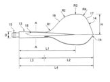
- FIG. 1 is a plan view of a dart according to an embodiment of the present invention.
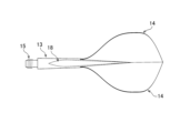
- FIG. 2 is a front view of the shaft and flight of the dart.
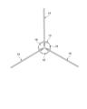
- FIG. 2 is a bottom view of the shaft and the flight.
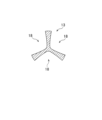
- FIG. 2 is a right side view of the shaft and the flight. This is a cross-sectional view taken along line AA in FIG.
- a dart 10 according to one embodiment of the present invention comprises, from the tip (front) to the base (rear), a tip (also called a point) 11, a barrel 12, and a shaft 13, in that order, and a flight 14 is attached and fixed to the base side of the shaft 13.
- a tip also called a point
- a flight 14 is attached and fixed to the base side of the shaft 13.
- the tip 11 is provided at the axial end of the dart 10 and is the part that is thrust into the target.
- the tip 11 is made of, for example, metal or plastic, and can be attached to and detached from the barrel 12 (replaceable) by a screw portion or the like (not shown).
- the barrel 12 is provided at the center of the dart 10 in the axial direction, and when throwing the dart 10, it is common to hold this barrel 12.
- the barrel 12 is mainly made of metal, and is heavy, which is effective for throwing the dart 10 farther.
- the barrel 12 can be made of various materials, such as brass, nickel alloy, and tungsten alloy, but those made of tungsten alloy or nickel alloy, which have a higher specific gravity, are thinner and less likely to interfere when hitting the target.
- the barrels 12 are various in shape, non-slip markings, weight, etc.
- the shaft 13 is provided at the base of the dart 10 in the axial direction, and the flight 14 is attached and fixed to the base side of the shaft 13, which is the part that exerts the effect of making the dart 10 fly straight.
- the flight 14 is the part that becomes the wing.
- the shaft 13 has a circular cross section, and gradually decreases in diameter (tapered) from the tip to the base in the axial direction, and can be attached and fixed (replaceable) by screwing it into the base end of the barrel 12 using a threaded portion (male thread) 15 provided at the tip.
- the maximum diameter D of the shaft 13 is, for example, about 4.5 mm to 6.5 mm, and the length L1 of the shaft 13 in the axial direction (length excluding the threaded portion 15) is, for example, about 45 mm to 60 mm, but is not particularly limited.
- the material of the shaft 13 may be various, such as metal, resin (plastic), polycarbonate, carbon composite, etc., and is not particularly limited as long as it can exhibit the above-mentioned effects, but it is preferable to use a polyamide-based resin.
- This polyamide-based resin has an amide bond, and is composed mainly of, for example, amino acid, lactam, or diamine and dicarboxylic acid.
- the shaft 13 and the flights 14 are preferably integrally molded (integrally structured) by injection molding using the same resin material, but the shaft and the flights can also be molded separately and then assembled. In this case, a slit is made in the base side of the shaft, and the flights can be inserted into the slit to attach and fix them.
- the materials of the shaft and the flights may be the same or different.
- equiangular positions refer to positions spaced 120 degrees apart around the axis of the shaft 13, but even if there is a deviation within a range of about ⁇ 1 degree (a range of 119 degrees to 121 degrees) due to manufacturing errors or the like, these positions are considered equiangular positions.
- the tips of the flights 14 are attached and fixed to the outer periphery of the shaft 13 from the center to the base side in the axial direction, and the base sides of the flights 14 protrude outward (rearward) from the shaft 13 in the axial direction of the base side and are connected to each other.
- the three flights 14 are arranged radially around the axial center of the dart 10.
- the attachment length of the flight 14 relative to the shaft 13 is, for example, approximately 50% to 80% (preferably 60% or more) of the length L2 of the flight 14 along the axial direction of the shaft 13, the height H of the flight 14 relative to the axial center of the shaft 13 is approximately 15 mm to 25 mm, and the length L3 of the shaft 13 in the axial direction where the flight 14 is not attached is approximately 20 mm to 30 mm, but is not particularly limited.
- the three flights 14 have the same shape, and can be shaped, for example, standard, shaped (hallows shape), kite, teardrop, slim, etc., and the outer peripheral contour of each flight 14 is formed, as shown in Fig. 2, by a curved surface that extends from the tip side to the base side along the axial direction of the shaft 13, and includes a tip side slope 16 having a gentle inclination angle and a base side slope 17 having a steeper inclination angle than the tip side slope 16.
- the radius of curvature R1 of the rising portion that constitutes the tip side slope 16 is about 8 mm to 13 mm
- the base side slope 17 rises at an angle of about 58 degrees to 65 degrees with respect to the axial center
- the radii of curvature R2, R3, and R4 from the tip side slope 16 to the base side slope 17 are, but are not particularly limited to, R2 being about 17 mm to 21 mm, R3 being larger than R2 and about 27 mm to 33 mm, and R4 being smaller than R2 and about 4 mm to 7 mm.
- the thickness of the flight 14 is usually about 0.3 mm to 0.5 mm
- the length L4 to the base end of the flight 14, including the length L1 of the shaft 13, is, for example, about 65 mm to 75 mm, but is not particularly limited.
- Grooves 18 are formed on the shaft 13 between flights 14 adjacent to each other in the circumferential direction of the shaft 13. Each groove 18 is formed at an equal angular position centered on the axis of the shaft 13.
- the equal angular positions refer to positions spaced at intervals of 120 degrees centered on the axis of the shaft 13, but even if there is a deviation within a range of about ⁇ 1 degree (a range of 119 degrees to 121 degrees) due to manufacturing errors or the like, these positions are included in the equal angular positions.
- the shape, inner width and depth of the groove 18 are set so that a later thrown dart 10 can smoothly slip through even if it collides with the dart 10 stuck in the target, without impairing the strength of the shaft 13.
- the three grooves 18 have the same shape, and their inner widths gradually become wider (inversely tapered) from the flight 14 side (the position where the three flights 14 are connected to one another) toward the axial center of the shaft 13, and gradually become narrower (tapered) from the axial center of the shaft 13 toward the barrel 12 side (in a region in the axial direction of the shaft 13 where no flights 14 exist). Also, the depth of each groove 18 gradually becomes deeper from the flight 14 side toward the axial center of the shaft 13, and gradually becomes shallower from the axial center of the shaft 13 toward the barrel 12 side (in a region in the axial direction of the shaft 13 where no flights 14 exist).
- the barrel 12 side end and flight 14 side end of the groove 18 are each acute-angled (V-shaped).
- the position where the inner width of the groove 18 is maximum is on the barrel 12 side (a region where the flight 14 does not exist in the axial direction of the shaft 13) at the center of the shaft 13, so the flight 14 side end of the groove 18 is more pointed (has a more acute angle) than the barrel 12 side end.
- the maximum inner width of the groove 18 is, for example, about 3 mm to 5 mm, but is not particularly limited. 4 and 5, the bottom surface of groove 18 has an arc-shaped cross section (curved line: for example, a radius of curvature of about 0.4 mm to 0.6 mm).
- the position where groove 18 has the greatest depth is the center in the axial direction of shaft 13 and on the barrel 12 side (a region in the axial direction of shaft 13 where no flight 14 exists).
- the position where the inner width of the groove 18 is maximum and the position where the depth is maximum are the same, but may be different.
- the dart 10 has three flights 14, the shaft 13 is gradually tapered from the tip to the base, and the grooves 18 are formed between adjacent flights 14 in the circumferential direction of the shaft 13. Therefore, when multiple darts 10 are thrown in succession, the tip 11 of the dart 10 thrown later will not collide with the base end of the shaft 13 of the dart 10 that has struck the target, causing the dart 10 thrown later to be knocked away, but will instead stick close to the dart 10 that has struck the target. Also, it is possible to suppress or even prevent the dart 10 that has struck the target from being knocked away by the dart 10 thrown later.
- the present invention has been described above with reference to one embodiment, the present invention is not limited to the configuration described in the above embodiment, and includes other embodiments and modifications that are conceivable within the scope of the claims.
- the dart of the present invention may be constructed by combining some or all of the above-mentioned examples and modifications, which are also included in the scope of the present invention.
- the shaft is described as being detachably attached to the base end of the barrel by a threaded portion provided at the tip of the shaft, but the shaft may also be configured so as not to be detachable from the barrel.
- the darts of the present invention can prevent or even prevent the later thrown darts from colliding with the darts already stuck in the target and being knocked away when multiple darts are thrown in succession, and can therefore achieve higher scores in competitions, and have industrial applicability, for example, in contributing to improved manufacturing and sales of darts.
Landscapes
- Engineering & Computer Science (AREA)
- General Engineering & Computer Science (AREA)
- Aiming, Guidance, Guns With A Light Source, Armor, Camouflage, And Targets (AREA)
- Toys (AREA)
- Gears, Cams (AREA)
Abstract
Description
本発明は、壁等に設置された的(ダーツボード)に投擲して得点等を競うスポーツ遊具に使用されるダーツに関する。 The present invention relates to darts, which are used as a sports toy in which players compete for points by throwing darts at a target (dart board) installed on a wall or other object.
ダーツ競技は、得点を競うスポーツ競技としてプロ競技も行なわれ広く発展している。具体的には、ダーツ(矢、ダート)を的に投擲して、その中心部の高得点を競う競技であり、いかに多くのダーツを的の中心部に投げることができるかが競われる。そのため、ダーツを的の中心にできるだけ集中して刺すことが要求される競技である。
従来、例えば、特許文献1~3に開示されたダーツが知られているが、このようなダーツを投擲した場合、先に投げたダーツが的に刺さった状態で、続けて次のダーツを投げるため、既に的に刺さったダーツに後から投げたダーツが衝突して弾かれ、同じ位置にダーツが刺さらないことがある。また、既に的に刺さったダーツが弾かれて的より離脱することがある。
そこで、本発明者らは、特許文献4に開示されたダーツを提案した。
Darts has developed widely as a sport where players compete for points, with professional competitions also taking place. Specifically, darts are thrown at a target, and the competition is based on how many darts can be thrown into the center of the target. Therefore, it is a sport where players are required to focus as much as possible on hitting the center of the target.
Darts disclosed in, for example, Patent Documents 1 to 3 are known in the art, but when such darts are thrown, the next dart is thrown after the first dart has already struck the target, so the dart thrown later collides with the dart already struck in the target and is bounced off, which means that the darts do not strike the same position. Also, the darts that have already struck the target may be bounced off and leave the target.
Therefore, the present inventors proposed the dart disclosed in Patent Document 4.
上記したダーツにより、後から投げたダーツが的に刺さったダーツに衝突して弾かれたり、また、後から投げたダーツにより的に刺さったダーツが弾き飛ばされたりすることを、従来よりも抑制できるが、更なる改善が望まれている。 The above-mentioned darts can prevent a later thrown dart from colliding with a dart already stuck in the target and being knocked away, or a later thrown dart from knocking the dart off the target, more than ever before, but further improvements are desired.
本発明はかかる事情に鑑みてなされたもので、後から投げたダーツが的に刺さったダーツに衝突して弾かれたり、また、後から投げたダーツにより的に刺さったダーツが弾き飛ばされたりすることを、従来よりも抑制、更には防止可能なダーツを提供することを目的とする。 The present invention was made in consideration of these circumstances, and aims to provide a dart that can suppress or even prevent a dart thrown later from colliding with a dart already stuck in the target and being knocked away, or a dart that has already stuck in the target from being knocked away by a dart thrown later, more than ever before.
前記目的に沿う本発明に係るダーツは、先側から基側へかけて、チップ、バレル、及び、シャフトを、順次備えたダーツにおいて、
前記シャフトは先側から基側へかけて徐々に縮径し、該シャフトの基側には、該シャフトの軸心を中心として等角度位置に3枚のフライトが取付け固定され、しかも、該フライトの基側は前記シャフトから突出して互いに連接し、
前記シャフトには、該シャフトの周方向に隣り合う前記フライトの間に溝が形成され、該溝の内幅が、前記フライト側から前記シャフトの軸心方向中央へかけて徐々に広くなり、かつ、該シャフトの軸心方向中央から前記バレル側へかけて徐々に狭くなる。
The dart according to the present invention, which is in accordance with the above-mentioned object, is a dart which is provided with a tip, a barrel, and a shaft in this order from the tip side to the base side,
The shaft is gradually tapered from the tip to the base, and three flights are attached and fixed to the base of the shaft at equal angular positions around the axis of the shaft, and the base sides of the flights protrude from the shaft and are connected to each other,
A groove is formed in the shaft between adjacent flights in the circumferential direction of the shaft, and the inner width of the groove gradually increases from the flight side toward the axial center of the shaft and gradually decreases from the axial center of the shaft toward the barrel side.
このように、フライトは、枚数が3枚であり、シャフトにその軸心を中心として等角度位置(120度間隔位置)に取付け固定されているので、シャフトの周方向に隣り合うフライトの間隔を、フライトの枚数が4枚の場合(90度間隔位置)よりも広くできるため、ダーツを続けて投げる際に、後から投げたダーツが、既に的に刺さったダーツのフライトに衝突しにくくなる。
また、シャフトは、先側から基側へかけて徐々に縮径した形状であり、フライトの基側は、シャフトから突出して互いに連接しているので、後から投げたダーツが、既に的に刺さったダーツのシャフトに衝突しにくくなり、衝突した場合でもスムーズにすり抜けることができる。
更に、シャフトには、その周方向に隣り合うフライトの間に溝を形成しているが、フライトの枚数を3枚とすることで、フライトの枚数が4枚の場合よりも、溝1つ当たりの断面積(シャフトの軸心方向に直交する面での面積)を大きくできるため、上記した作用効果が更に高められる。なお、溝の内幅は、シャフトの軸心方向にフライト側からバレル側へかけて、徐々に広くした後に徐々に狭くしているので、シャフトの強度を損なうことなく、また、後から投げたダーツのチップ先端が、既に的に刺さったダーツに衝突した場合でも、スムーズにすり抜けることができる。
In this way, there are three flights, which are attached and fixed to the shaft at equal angular positions (120 degree intervals) around the axis of the shaft. Therefore, the interval between adjacent flights in the circumferential direction of the shaft can be made wider than when there are four flights (90 degree intervals). As a result, when darts are thrown in succession, a dart thrown later is less likely to collide with the flight of a dart that has already hit the target.
In addition, the shaft is gradually tapered from the tip to the base, and the base sides of the flights protrude from the shaft and are connected to each other, so that a dart thrown later is less likely to collide with the shaft of a dart that has already hit the target, and even if a collision does occur, the two darts can slip through each other smoothly.
Furthermore, the shaft has grooves between adjacent flights in the circumferential direction, and by making the number of flights three, the cross-sectional area per groove (area on a surface perpendicular to the shaft axis) can be made larger than when the number of flights is four, further enhancing the above-mentioned effects. The inner width of the groove gradually widens and then gradually narrows from the flight side to the barrel side in the shaft axis direction, so that the strength of the shaft is not impaired, and even if the tip of a dart thrown later collides with a dart already stuck in the target, it can smoothly slip through.
ここで、前記溝の深さは、前記フライト側から前記シャフトの軸心方向中央へかけて徐々に深くなり、かつ、該シャフトの軸心方向中央から前記バレル側へかけて徐々に浅くなることが好ましい。
また、3つの前記溝は、同一形状であり、しかも、前記シャフトの軸心を中心として等角度位置に形成されていることが好ましい。
更に、前記シャフトを前記バレルに取付け取外し可能とすることができる。
Here, it is preferable that the depth of the groove gradually becomes deeper from the flight side toward the center in the axial direction of the shaft, and gradually becomes shallower from the center in the axial direction of the shaft toward the barrel side.
It is also preferable that the three grooves have the same shape and are formed at equiangular positions about the axis of the shaft.
Furthermore, the shaft may be detachably attached to the barrel.
本発明に係るダーツは、例えば、複数本のダーツを続けて投げる際に、後から投げたダーツが、的に刺さったダーツのフライトに衝突しにくくなり、また、後から投げたダーツのチップ先端が、的に刺さったダーツに衝突した場合でも、スムーズにすり抜けることができる。
従って、従来のダーツと比較して、後から投げたダーツは、的に刺さったダーツによって大きく弾き飛ばされることなく、このダーツに近い位置で的に刺さることができるため、又は、後から投げたダーツにより的に刺さったダーツが弾き飛ばされて的から離脱することを従来よりも抑制、更には防止できるため、競技等では高得点を挙げることが可能となる。
The dart of the present invention, for example, when throwing multiple darts in succession, makes it difficult for the later-thrown dart to collide with the flight of the dart that has already hit the target, and even if the tip of the later-thrown dart collides with the dart that has already hit the target, it can smoothly pass through.
Therefore, compared to conventional darts, the dart thrown later can strike the target at a position close to the dart that has already struck the target without being knocked away by the dart that has already struck the target. Alternatively, the dart that has already struck the target can be prevented from being knocked away by the dart thrown later and leaving the target, which makes it possible to score higher in competitions.
続いて、添付した図面を参照しつつ、本発明を具体化した実施例につき説明し、本発明の理解に供する。
図1~図4に示すように、本発明の一実施例に係るダーツ10は、先側(前側)から基側(後ろ側)へかけて、チップ(ポイントとも称す)11、バレル12、及び、シャフト13を順次備え、シャフト13の基側には、フライト14が取付け固定されたものであり、複数のダーツ10を続けて投げる際に、後から投げたダーツ10が、先に投げて的(標的:図示しない)に刺さったダーツ10に衝突して弾かれたり、また、後から投げたダーツ10により、的に刺さったダーツ10が弾き飛ばされたりすることを、従来よりも抑制、更には防止可能なものである。
以下、詳しく説明する。
Next, with reference to the attached drawings, an embodiment of the present invention will be described for better understanding of the present invention.
As shown in Figures 1 to 4, a
The details are explained below.
チップ11は、図1に示すように、ダーツ10の軸心方向先部に設けられ、的に突き刺さる部分である。
このチップ11は、例えば、金属製やプラスチック製であり、ねじ部等(図示しない)により、バレル12に取付け取外し可能(交換可能)にすることができる。
As shown in FIG. 1, the
The
バレル12は、図1に示すように、ダーツ10の軸心方向中央部に設けられ、ダーツ10を投げる場合は、このバレル12を持つことが一般的である。
このバレル12は、主として金属製であり、重量があってダーツ10を遠くに投げるための効果がある。バレル12の材質としては、例えば、真鍮(しんちゅう)、ニッケル合金、タングステン合金など様々であるが、比重の重いタングステン合金やニッケル合金で造られたものの方がより細くなり、的に当たった際に干渉しにくい。
なお、バレル12は、形状、滑り止めの刻み、重量等が様々である。
As shown in FIG. 1 , the
The
The
シャフト13は、図1~図5に示すように、ダーツ10の軸心方向基部に設けられ、シャフト13の基側にフライト14が取付け固定され、ダーツ10が真直ぐ飛ぶための効果を発揮する部分である。即ち、フライト14は翼となる部分である。
このシャフト13は、断面円形状であり、その軸心方向に先側から基側へかけて徐々に縮径し(テーパ状となっており)、その先端部に設けられたねじ部(雄ねじ)15により、バレル12の基端部にねじ込んで取付け固定できる(交換可能にできる)。なお、シャフト13の最大径(ねじ部15を除いた先端の径)Dは、例えば、4.5mm~6.5mm程度であり、シャフト13の軸心方向の長さ(ねじ部15を除いた長さ)L1は、例えば、45mm~60mm程度であるが、特に限定されるものではない。
1 to 5, the
The
シャフト13の材質には、例えば、金属、樹脂(プラスチック)、ポリカーボネイト、カーボンコンポジットなど様々なものを使用でき、上記効果を発揮できれば、特に限定されるものではないが、ポリアミド系樹脂を使用するのがよい。このポリアミド系樹脂とは、アミド結合を有するものであり、例えば、アミノ酸、ラクタム、又は、ジアミンと、ジカルボン酸を主たる構成成分としたものである。
ここで、シャフト13とフライト14は、同じ材質の樹脂を用いて射出成形することにより、一体成形する(一体構造とする)ことが好ましいが、シャフトとフライトを別々に成形して組合せることもできる。この場合、シャフトの基側に切れ込みを入れ、この切れ込みにフライトを差し込むことで取付け固定できる。なお、シャフトとフライトの材質は、同じでもよく、また、異なってもよい。
The material of the
Here, the
シャフト13の基側には、3枚のフライト14が、シャフト13の軸心を中心として等角度位置に取付け固定されている(形成されている)。ここで、等角度位置とは、シャフト13の軸心を中心として120度間隔の位置であるが、製造上の誤差等により、例えば、±1度程度の範囲(119度~121度の範囲)でずれる場合も等角度位置に含まれる。
フライト14の先側は、シャフト13の軸心方向中央から基側にかけての外周に取付け固定され、フライト14の基側は、シャフト13からその軸心方向基側外方(後方)へ突出して互いに連接している。このため、図4に示すように、ダーツ10の後方からダーツ10を視ると、3枚のフライト14は、ダーツ10の軸心を中心として放射状に配置される。
なお、シャフト13に対するフライト14の取付け長さは、例えば、シャフト13の軸心方向に沿うフライト14の長さL2の50%以上80%以下(好ましくは、60%以上)程度であり、シャフト13の軸心に対するフライト14の高さHは15mm~25mm程度であり、また、フライト14が取付けられていないシャフト13の軸心方向の長さL3は20mm~30mm程度であるが、特に限定されるものではない。
Three
The tips of the
The attachment length of the
3枚のフライト14は同一形状であり、例えば、スタンダード、シェイプ(ハローズ・シェイプ)、カイト、ティアドロップ、スリム等の形状にでき、各フライト14の外周輪郭は、図2に示すように、シャフト13の軸心方向に沿って、その先側から基側へかけて、緩やかな傾斜角度の先側斜面16と、この先側斜面16よりも急な傾斜角度の基側斜面17が連接した曲面で構成されている。具体的には、先側斜面16を構成する立上がり部の曲率半径R1は8mm~13mm程度であり、基側斜面17は軸心に対して58度~65度程度で立ち上がり、先側斜面16から基側斜面17にかけての曲率半径R2、R3、R4はそれぞれ、R2が17mm~21mm程度、R3がR2より大きく27mm~33mm程度、R4がR2より小さく4mm~7mm程度であるが、特に限定されるものではない。
また、フライト14の厚みは通常0.3mm~0.5mm程度であり、シャフト13の長さL1も含めたフライト14基端までの長さL4は、例えば、65mm~75mm程度であるが、特に限定されるものではない。
The three
The thickness of the
シャフト13には、シャフト13の周方向に隣り合うフライト14とフライト14の間に、溝18が形成されている(合計3つ)。各溝18は、シャフト13の軸心を中心として等角度位置に形成されている。ここで、等角度位置とは、シャフト13の軸心を中心として120度間隔の位置であるが、製造上の誤差等により、例えば、±1度程度の範囲(119度~121度の範囲)でずれる場合も等角度位置に含まれる。
溝18は、シャフト13の強度を損なうことなく、後から投げたダーツ10が的に刺さったダーツ10に衝突してもスムーズにすり抜けられるように、その形状、内幅、及び、深さを設定している。
3つの溝18は同一形状であり、その内幅が、フライト14側(3枚のフライト14が互いに連接する位置)からシャフト13の軸心方向中央へかけて徐々に広く(逆テーパ状に)なり、かつ、シャフト13の軸心方向中央からバレル12側へかけて(シャフト13の軸心方向でフライト14が存在しない領域で)徐々に狭く(テーパ状に)なっている。また、各溝18の深さは、フライト14側からシャフト13の軸心方向中央へかけて徐々に深くなり、かつ、シャフト13の軸心方向中央からバレル12側へかけて(シャフト13の軸心方向でフライト14が存在しない領域で)徐々に浅くなっている。
Grooves 18 (three in total) are formed on the
The shape, inner width and depth of the
The three
上記した溝18のバレル12側端部とフライト14側端部はそれぞれ、鋭角状(V字状)となっている。この溝18の内幅が最大となる位置は、シャフト13の軸心方向中央でバレル12側(シャフト13の軸心方向でフライト14が存在しない領域)であるため、溝18のフライト14側端部はバレル12側端部よりも、より尖っている(より鋭角状になっている)。なお、溝18の最大内幅は、例えば、3mm~5mm程度であるが、特に限定されるものではない。
また、溝18の底面は、図4、5に示すように、断面円弧状(曲線:例えば、曲率半径が0.4mm~0.6mm程度)になっている。この溝18の深さが最大となる位置は、シャフト13の軸心方向中央でバレル12側(シャフト13の軸心方向でフライト14が存在しない領域)である。
なお、上記した溝18の内幅が最大となる位置と、深さが最大となる位置は、同じであるが、異なってもよい。
The
4 and 5, the bottom surface of
The position where the inner width of the
上記したように、ダーツ10は、フライト14の枚数を3枚とし、シャフト13を先側から基側へかけて徐々に縮径した形状とし、更に、シャフト13の周方向に隣り合うフライト14とフライト14の間に上記した構成の溝18を形成している。このため、複数のダーツ10を続けて投げる際に、後から投げたダーツ10のチップ11先端が、的に刺さったダーツ10のシャフト13の基端に衝突して、後から投げたダーツ10が弾き飛ばされるということがなく、的に刺さったダーツ10の近くに刺さることになる。また、的に刺さったダーツ10が、後から投げたダーツ10によって弾き飛ばされることを、従来よりも抑制、更には防止できる。
As described above, the
以上、本発明を、一実施例を参照して説明してきたが、本発明は何ら上記した実施例の形態に記載の構成に限定されるものではなく、請求の範囲に記載されている事項の範囲内で考えられるその他の実施例や変形例も含むものである。例えば、前記したそれぞれの実例や変形例の一部又は全部を組合せて本発明のダーツを構成する場合も本発明の権利範囲に含まれる。
前記実施例においては、シャフトが、その先端部に設けられたねじ部により、バレルの基端部に取付け取外し可能となっている場合について説明したが、シャフトがバレルから取り外せない構成とすることもできる。
Although the present invention has been described above with reference to one embodiment, the present invention is not limited to the configuration described in the above embodiment, and includes other embodiments and modifications that are conceivable within the scope of the claims. For example, the dart of the present invention may be constructed by combining some or all of the above-mentioned examples and modifications, which are also included in the scope of the present invention.
In the above embodiment, the shaft is described as being detachably attached to the base end of the barrel by a threaded portion provided at the tip of the shaft, but the shaft may also be configured so as not to be detachable from the barrel.
本発明のダーツによれば、複数本のダーツを続けて投げる際に、後から投げたダーツが的に刺さったダーツに衝突して弾かれたりすること、また、後から投げたダーツにより的に刺さったダーツが弾き飛ばされたりすることを、従来よりも抑制、更には防止でき、競技等では高得点を挙げることが可能となるため、例えば、ダーツの製造販売の向上に寄与できるといった産業上の利用可能性がある。 The darts of the present invention can prevent or even prevent the later thrown darts from colliding with the darts already stuck in the target and being knocked away when multiple darts are thrown in succession, and can therefore achieve higher scores in competitions, and have industrial applicability, for example, in contributing to improved manufacturing and sales of darts.
10:ダーツ、11:チップ、12:バレル、13:シャフト、14:フライト、15:ねじ部、16:先側斜面、17:基側斜面、18:溝 10: Dart, 11: Tip, 12: Barrel, 13: Shaft, 14: Flight, 15: Threaded part, 16: Tip bevel, 17: Base bevel, 18: Groove
Claims (4)
前記シャフトは先側から基側へかけて徐々に縮径し、該シャフトの基側には、該シャフトの軸心を中心として等角度位置に3枚のフライトが取付け固定され、しかも、該フライトの基側は前記シャフトから突出して互いに連接し、
前記シャフトには、該シャフトの周方向に隣り合う前記フライトの間に溝が形成され、該溝の内幅が、前記フライト側から前記シャフトの軸心方向中央へかけて徐々に広くなり、かつ、該シャフトの軸心方向中央から前記バレル側へかけて徐々に狭くなることを特徴とするダーツ。 A dart having a tip, a barrel, and a shaft in that order from the tip to the base.
The shaft is gradually tapered from the tip to the base, and three flights are attached and fixed to the base of the shaft at equal angular positions around the axis of the shaft, and the base sides of the flights protrude from the shaft and are connected to each other,
A groove is formed in the shaft between adjacent flights in the circumferential direction of the shaft, and an inner width of the groove gradually increases from the flight side toward the axial center of the shaft, and gradually decreases from the axial center of the shaft toward the barrel side.
Priority Applications (6)
| Application Number | Priority Date | Filing Date | Title |
|---|---|---|---|
| US18/856,148 US20250271244A1 (en) | 2023-06-07 | 2023-06-07 | Dart |
| EP23804884.7A EP4725566A4 (en) | 2023-06-07 | 2023-06-07 | ARROW |
| PCT/JP2023/021205 WO2024252573A1 (en) | 2023-06-07 | 2023-06-07 | Dart |
| CA3245929A CA3245929A1 (en) | 2023-06-07 | 2023-06-07 | Dart |
| JP2023571226A JP7588908B1 (en) | 2023-06-07 | 2023-06-07 | darts |
| CN202380012013.8A CN119451731A (en) | 2023-06-07 | 2023-06-07 | Darts |
Applications Claiming Priority (1)
| Application Number | Priority Date | Filing Date | Title |
|---|---|---|---|
| PCT/JP2023/021205 WO2024252573A1 (en) | 2023-06-07 | 2023-06-07 | Dart |
Publications (1)
| Publication Number | Publication Date |
|---|---|
| WO2024252573A1 true WO2024252573A1 (en) | 2024-12-12 |
Family
ID=93588001
Family Applications (1)
| Application Number | Title | Priority Date | Filing Date |
|---|---|---|---|
| PCT/JP2023/021205 Ceased WO2024252573A1 (en) | 2023-06-07 | 2023-06-07 | Dart |
Country Status (6)
| Country | Link |
|---|---|
| US (1) | US20250271244A1 (en) |
| EP (1) | EP4725566A4 (en) |
| JP (1) | JP7588908B1 (en) |
| CN (1) | CN119451731A (en) |
| CA (1) | CA3245929A1 (en) |
| WO (1) | WO2024252573A1 (en) |
Citations (6)
| Publication number | Priority date | Publication date | Assignee | Title |
|---|---|---|---|---|
| JP3160281U (en) | 2010-04-09 | 2010-06-17 | 株式会社ハマダ工商 | Darts blade structure |
| JP2011110413A (en) | 2009-11-26 | 2011-06-09 | Chuyo Seiko Co Ltd | Dart |
| JP3172260U (en) * | 2011-09-29 | 2011-12-08 | 政則 寺田 | Dart barrel |
| JP2012239635A (en) * | 2011-05-19 | 2012-12-10 | Eva-Japan Co Ltd | Dart and dart flight |
| JP2013121368A (en) * | 2011-12-09 | 2013-06-20 | Felix Corp | Dart |
| JP5432785B2 (en) | 2010-03-18 | 2014-03-05 | 株式会社ハマダ工商 | Darts |
Family Cites Families (117)
| Publication number | Priority date | Publication date | Assignee | Title |
|---|---|---|---|---|
| US619762A (en) * | 1899-02-21 | Amos kissinger and william c | ||
| US600772A (en) * | 1897-05-22 | 1898-03-15 | Toy dart | |
| US1928768A (en) * | 1931-04-25 | 1933-10-03 | Charles J Sell | Game of simulated golf played with darts |
| US2119524A (en) * | 1937-04-24 | 1938-06-07 | Char Yew | Exploding dart |
| US2182296A (en) * | 1937-11-04 | 1939-12-05 | Lowy Ferenc | Dart |
| US2499029A (en) * | 1945-08-03 | 1950-02-28 | Robert M Mcelroy | Casting dart |
| US2432209A (en) * | 1945-10-20 | 1947-12-09 | Harry W Osgood | Driving tee for projectiles |
| US2504757A (en) * | 1947-10-17 | 1950-04-18 | Robert S Terry | Dart |
| US2620190A (en) * | 1947-11-10 | 1952-12-02 | Bean Donald | Tip for darts and arrows |
| US2828965A (en) * | 1955-06-01 | 1958-04-01 | Schwitzki Elvino | Arrows and darts |
| US3275321A (en) * | 1964-01-30 | 1966-09-27 | Gerard M Forest | Target apparatus with discriminating electrical indicator, and projectiles therefor |
| US3596910A (en) * | 1969-06-13 | 1971-08-03 | Hasbro Industries Inc | Dart with longitudinally adjustable vanes |
| US3672678A (en) * | 1970-11-03 | 1972-06-27 | Hasbro Industries Inc | Dart construction |
| US3865374A (en) * | 1974-01-22 | 1975-02-11 | Jr Fernando Troncoso | Arrow locating device |
| US3957271A (en) * | 1975-03-17 | 1976-05-18 | Kulite Tungsten Corporation | Selectively adjustable darts |
| US3976298A (en) * | 1975-06-16 | 1976-08-24 | Hinchman Leray V | Dart |
| US4032147A (en) * | 1976-05-17 | 1977-06-28 | Fansteel Inc. | Composite dart body |
| US4109915A (en) * | 1976-09-20 | 1978-08-29 | Bottelsen Walter Edward | Breakaway dart |
| US4212464A (en) * | 1978-02-15 | 1980-07-15 | Fansteel Inc. | Dart body |
| GB2026332A (en) * | 1978-07-28 | 1980-02-06 | Ollis M | Darts |
| GB2029711B (en) * | 1978-09-14 | 1982-08-25 | Manghat G | Darts |
| US4230322A (en) * | 1979-01-22 | 1980-10-28 | Bottelsen Walter E | No bounce dart |
| GB2049448A (en) * | 1979-03-16 | 1980-12-31 | Williams F L | Darts |
| GB2067420A (en) * | 1980-01-15 | 1981-07-30 | Woodrow I G | Darts |
| US4487420A (en) * | 1980-03-10 | 1984-12-11 | Ollis Martin G | Darts |
| GB2079613A (en) * | 1980-07-18 | 1982-01-27 | Frost Kenneth Frederick | Darts |
| GB2085740A (en) * | 1980-09-04 | 1982-05-06 | Durro Flights Ltd | Darts |
| US4722531A (en) * | 1982-08-30 | 1988-02-02 | Schram Donald E | Take-down arrow |
| US4537176A (en) * | 1983-01-18 | 1985-08-27 | Gary D. Johnson | Blow dart game including hollow tube and dart with target impacting member and shock-absorbing portion |
| GB2156697B (en) * | 1984-04-06 | 1987-11-11 | Target Sports Ltd | Dart flight stem |
| GB2163058A (en) * | 1984-07-26 | 1986-02-19 | Stanley Murray | Darts |
| GB8519284D0 (en) * | 1985-07-31 | 1985-09-04 | Nisbet H B | Hand thrown projectile |
| GB2180461A (en) * | 1985-09-19 | 1987-04-01 | Ian George Woodrow | Darts |
| US4596393A (en) * | 1985-10-21 | 1986-06-24 | Mihkel Orav | Anti-bounce-back dart |
| US4697815A (en) * | 1986-07-25 | 1987-10-06 | 139316 Canada Inc | Dart |
| IE862774L (en) * | 1986-10-21 | 1988-04-21 | Joseph Raymond Mccabe | Darts. |
| US4840383A (en) * | 1987-10-29 | 1989-06-20 | Lombardo James W | Illuminated dart |
| US5067728A (en) * | 1988-01-25 | 1991-11-26 | Harvard Sports, Inc. | Lawn dart with safety feature |
| US4946172A (en) * | 1989-02-16 | 1990-08-07 | Franklin Sports Industries, Inc. | Safety dart |
| US4989881A (en) * | 1989-02-28 | 1991-02-05 | Gamble Christopher L | Illuminated sports projectile |
| US4997190A (en) * | 1989-12-27 | 1991-03-05 | Chmela John F | Lawn dart |
| US5058900A (en) * | 1990-10-31 | 1991-10-22 | Progenics Corporation | General purpose illuminator assembly |
| US5118117A (en) * | 1991-01-08 | 1992-06-02 | Progenics Corporation | Recreational dart |
| US5498004A (en) * | 1991-09-30 | 1996-03-12 | Kulite Tungsten Corporation | Game dart |
| US5223667A (en) * | 1992-01-21 | 1993-06-29 | Bei Electronics, Inc. | Plural piece flechettes affording enhanced penetration |
| GB2264441B (en) * | 1992-02-28 | 1995-05-17 | Raymond Cyril Morris | A dart |
| US5324044A (en) * | 1992-04-24 | 1994-06-28 | Dart Mart, Inc. | Dart assembly |
| US5207434A (en) * | 1992-07-06 | 1993-05-04 | Oudekerk Timothy K | Throwing dart with collapsible tail portion |
| US5333881A (en) * | 1993-01-15 | 1994-08-02 | Cugliari Gregory A | Game tracking and weapon locating device |
| US5375850A (en) * | 1993-04-22 | 1994-12-27 | Pickett; Michael R. | Dart |
| US5425542A (en) * | 1993-05-12 | 1995-06-20 | Blackwood; James D. | Illuminated projectile |
| US5388840A (en) * | 1994-03-23 | 1995-02-14 | Werle; Sean F. | Throwing dart flight with stepped configuration |
| GB2288986B (en) * | 1994-05-04 | 1997-12-10 | Target Sports Ltd | Dart flight stem |
| US5427385A (en) * | 1994-10-17 | 1995-06-27 | Conrad; Phillip J. | Fletch replacement device |
| TW408619U (en) * | 1995-07-11 | 2000-10-11 | Unicorn Products Ltd | Darts for the game og darts |
| US6277041B1 (en) * | 1995-11-17 | 2001-08-21 | George E. Fenn | Dart having resiliently mounted point and flight shaft, and user-modifiable body and weighting features |
| JP2000510025A (en) * | 1996-10-31 | 2000-08-08 | ペトラノフ,トーマス,アラン | Practice spear |
| KR19980027614U (en) * | 1996-11-18 | 1998-08-05 | 김용철 | Magnetic Arrow for Darts |
| US5899824A (en) * | 1997-02-12 | 1999-05-04 | Accudart Corporation | Snap-fit dart and adapter |
| US5895331A (en) * | 1997-09-12 | 1999-04-20 | Woodcraft Supply Corporation | Custom darts and their manufacture |
| DE19740367C2 (en) * | 1997-09-13 | 1998-12-24 | Sunflex Sport Schnellbuegel & | Dart |
| US5967915A (en) * | 1998-02-19 | 1999-10-19 | Lu; Kuo-Hui | Dart |
| US6267698B1 (en) * | 2000-02-04 | 2001-07-31 | Mihkel Orav | Soft tip game dart |
| US6595880B2 (en) * | 2001-07-20 | 2003-07-22 | Phillip R. Becker | Fluted arrow |
| US6533688B1 (en) * | 2001-10-17 | 2003-03-18 | Kou-Hwa Huang | Dart with rotary flight and light means |
| US6764420B2 (en) * | 2002-03-12 | 2004-07-20 | Talon Industries, Llc | Detachable nock for detaching a locator from an arrow |
| US6758772B1 (en) * | 2003-05-29 | 2004-07-06 | Robert Paul Chambers | Darts |
| US6758773B1 (en) * | 2003-10-21 | 2004-07-06 | Forhouse Corporation | Flashing dart |
| US6869374B1 (en) * | 2004-02-23 | 2005-03-22 | Keith E. Lane | Outdoor dart game |
| US20060154756A1 (en) * | 2004-12-10 | 2006-07-13 | Chia-Mu Shao | Dart with adjustable weight |
| US7108620B1 (en) * | 2005-01-12 | 2006-09-19 | Chih Hao Yiu | Game dart having ballast |
| DE202005003969U1 (en) * | 2005-03-11 | 2005-06-02 | Yiu, Chih Hao | Hand-thrown dart has hollow shank whose end-apertures are of smaller diameter than the inner diameter of the shank holding ballast |
| US20070029732A1 (en) * | 2005-08-08 | 2007-02-08 | Lockermate Corporation | Locker dart game system |
| US7241236B1 (en) * | 2006-01-12 | 2007-07-10 | Te-Tsao Chen | Dart with dual action arrangement |
| US7578508B2 (en) * | 2006-07-13 | 2009-08-25 | Mga Entertainment, Inc. | Skinnable rotating dart board game |
| KR200434932Y1 (en) * | 2006-09-22 | 2007-01-02 | 이영화 | Magnetic dart writing instruments |
| US20080090684A1 (en) * | 2006-10-12 | 2008-04-17 | Martinez Kelly M | Dart |
| KR20080000532U (en) * | 2006-10-13 | 2008-04-17 | 이영화 | Magnetic Dart Pin with Shock Absorbing Structure |
| FR2923724B3 (en) * | 2007-11-16 | 2010-02-05 | Jean Andre Lechleiter | GAME DARTS, LARGE |
| US7874947B1 (en) * | 2007-12-21 | 2011-01-25 | Fundex Games Ltd. | Lawn dart |
| US20090291786A1 (en) * | 2008-05-22 | 2009-11-26 | Grace Liao | Dart Having An Adjustable Barycenter |
| JP4350154B1 (en) * | 2008-09-10 | 2009-10-21 | 株式会社コスモ精機 | Darts |
| TWM358657U (en) * | 2008-12-31 | 2009-06-11 | jia-jing Cai | Body of dart |
| KR20100123287A (en) * | 2009-05-15 | 2010-11-24 | 김민식 | Tip safekeeping for dartpin |
| US8366573B2 (en) * | 2010-03-04 | 2013-02-05 | Hunt C Timothy | Light-emitting components for arrows |
| US8366572B1 (en) * | 2010-08-27 | 2013-02-05 | Joyce Peter B | Throwing arrow |
| US9011281B2 (en) * | 2010-12-16 | 2015-04-21 | Rac Em Bac, L.L.C. | Ammunition delivery system arrowhead and method of use |
| KR20120102273A (en) * | 2011-03-08 | 2012-09-18 | 임재윤 | Capacitive sensing dart pins for touch panel |
| US10371481B2 (en) * | 2012-02-21 | 2019-08-06 | Lanny L. Johnson | Tactile biofeedback reference attachment |
| US20130217523A1 (en) * | 2012-02-21 | 2013-08-22 | Lanny L. Johnson | Sports equipment handle having tactile biofeedback reference feature |
| US9982963B2 (en) * | 2012-02-21 | 2018-05-29 | Lanny L. Johnson | Firearm having tactile biofeedback reference feature |
| US20130220160A1 (en) * | 2012-02-28 | 2013-08-29 | Robert Van Burdine | Flechette delivered rfid |
| US8602926B2 (en) * | 2012-04-17 | 2013-12-10 | The Bohning Company, Ltd | Composite arrow vane |
| US8795109B2 (en) * | 2012-10-08 | 2014-08-05 | Evrio, Inc. | Arrow construction system having tip canister electronics |
| KR20140061624A (en) * | 2012-11-13 | 2014-05-22 | 문소라 | Dart pin including plurity of flights |
| KR101439909B1 (en) * | 2013-02-22 | 2014-11-03 | 백동재 | Dart |
| US9109863B2 (en) * | 2013-03-15 | 2015-08-18 | Andrew W. York | Vibrating projectile |
| KR101633664B1 (en) * | 2014-07-31 | 2016-06-27 | 주식회사 홍인터내셔날 | User identifiable dart pin |
| KR101507974B1 (en) * | 2014-12-03 | 2015-04-07 | 주식회사 제네스트 | Barral capable of controlling center of gravity |
| CN204709742U (en) * | 2015-06-04 | 2015-10-21 | 杜经初 | A kind of dartlike weapon with three leaf empennages |
| CN107019891A (en) * | 2016-01-29 | 2017-08-08 | 厦门协力胜贸易有限公司 | A kind of novel structure dartlike weapon |
| JP5974196B1 (en) * | 2016-03-02 | 2016-08-23 | 甚太 芹澤 | Screw member, fastening member and dart |
| DE102016106989B4 (en) * | 2016-04-15 | 2020-07-16 | Colin Bennett | Shaft for a dart arrow |
| US10684105B2 (en) * | 2018-07-18 | 2020-06-16 | Daniel Jones Hill | Arrow fletching apparatus with tapered body |
| CN108905128A (en) * | 2018-09-29 | 2018-11-30 | 陈档财 | A kind of dartlike weapon inserting empennage |
| CN209075982U (en) * | 2018-09-29 | 2019-07-09 | 陈档财 | A kind of dartlike weapon equipped with reinforcement bone |
| WO2020121522A1 (en) * | 2018-12-14 | 2020-06-18 | 株式会社Target Sports Japan | Dart shaft, dart member, and dart |
| JP7320397B2 (en) * | 2019-07-26 | 2023-08-03 | 株式会社ダーツライブ | throwing equipment |
| JP7399458B2 (en) * | 2019-11-19 | 2023-12-18 | 株式会社コスモ精機 | darts |
| CN212187707U (en) * | 2020-02-20 | 2020-12-22 | 深圳信息职业技术学院 | A side insert dart shaft and dart |
| JP7401137B2 (en) * | 2020-07-21 | 2023-12-19 | 三宅ハイテックジャパン株式会社 | darts |
| DE202021101319U1 (en) * | 2021-03-16 | 2021-04-28 | Didier Krampfl | Dart tip clamping system |
| TWI777488B (en) * | 2021-04-12 | 2022-09-11 | 銳緻股份有限公司 | Magnetic induction dart and magnetic induction dart system |
| US12066280B2 (en) * | 2021-10-26 | 2024-08-20 | Clifford Harlan | Dart and dart game |
| CN218833520U (en) * | 2022-09-28 | 2023-04-11 | 泰哲(天津)国际贸易有限公司 | Connection structure between dart barrel and dart shaft |
| FI13341Y1 (en) * | 2023-02-08 | 2023-03-13 | Kimmo Aaltonen | Dart |
| CZ310568B6 (en) * | 2024-05-02 | 2025-12-10 | Radim Novák | A dart body and a dart containing such body |
-
2023
- 2023-06-07 WO PCT/JP2023/021205 patent/WO2024252573A1/en not_active Ceased
- 2023-06-07 CA CA3245929A patent/CA3245929A1/en active Pending
- 2023-06-07 US US18/856,148 patent/US20250271244A1/en active Pending
- 2023-06-07 JP JP2023571226A patent/JP7588908B1/en active Active
- 2023-06-07 EP EP23804884.7A patent/EP4725566A4/en active Pending
- 2023-06-07 CN CN202380012013.8A patent/CN119451731A/en active Pending
Patent Citations (7)
| Publication number | Priority date | Publication date | Assignee | Title |
|---|---|---|---|---|
| JP2011110413A (en) | 2009-11-26 | 2011-06-09 | Chuyo Seiko Co Ltd | Dart |
| JP5432785B2 (en) | 2010-03-18 | 2014-03-05 | 株式会社ハマダ工商 | Darts |
| JP3160281U (en) | 2010-04-09 | 2010-06-17 | 株式会社ハマダ工商 | Darts blade structure |
| JP2012239635A (en) * | 2011-05-19 | 2012-12-10 | Eva-Japan Co Ltd | Dart and dart flight |
| JP3172260U (en) * | 2011-09-29 | 2011-12-08 | 政則 寺田 | Dart barrel |
| JP2013121368A (en) * | 2011-12-09 | 2013-06-20 | Felix Corp | Dart |
| JP5748345B2 (en) | 2011-12-09 | 2015-07-15 | 株式会社フェリックス | Darts |
Non-Patent Citations (1)
| Title |
|---|
| See also references of EP4725566A4 |
Also Published As
| Publication number | Publication date |
|---|---|
| JP7588908B1 (en) | 2024-11-25 |
| CA3245929A1 (en) | 2025-06-13 |
| US20250271244A1 (en) | 2025-08-28 |
| EP4725566A1 (en) | 2026-04-15 |
| CN119451731A (en) | 2025-02-14 |
| EP4725566A4 (en) | 2026-07-15 |
| JPWO2024252573A1 (en) | 2024-12-12 |
Similar Documents
| Publication | Publication Date | Title |
|---|---|---|
| US8348789B1 (en) | Throwing toy with tail and in-line tab grip | |
| US7874947B1 (en) | Lawn dart | |
| JP5947653B2 (en) | Golf club head | |
| JP2018015564A (en) | Striking face deflection structures in golf club | |
| US11940257B2 (en) | High performance foam dart having ridges | |
| US7364521B2 (en) | Sucker with an annular projection on adhesion surface and adhesion arrow having the sucker | |
| US12253344B2 (en) | Dart | |
| JPH09299519A (en) | Golf club head | |
| US20130167820A1 (en) | Sport blow gun | |
| JP7588908B1 (en) | darts | |
| US20090048032A1 (en) | Shaft of cue sticks | |
| JPWO2024252573A5 (en) | ||
| CN209752111U (en) | Golf club head | |
| US12480750B2 (en) | Foam dart having a safety cap with polygonal apertures | |
| US10989506B1 (en) | Dart | |
| JP7320397B2 (en) | throwing equipment | |
| US20180178088A1 (en) | Wood-type golf club head | |
| JP5748345B2 (en) | Darts | |
| GB2531362A (en) | Improvements to dart flights | |
| WO2024187449A1 (en) | Component part for a dart | |
| US20250288901A1 (en) | Toy Projectile Having Impact Head with Multiple Flexible Prongs | |
| US4478421A (en) | Dart body with a spinning head | |
| US9597560B2 (en) | Golf club head | |
| GB2026879A (en) | Dartboard spider | |
| AU2002329494B2 (en) | A sports bat |
Legal Events
| Date | Code | Title | Description |
|---|---|---|---|
| WWE | Wipo information: entry into national phase |
Ref document number: 2023571226 Country of ref document: JP |
|
| WWE | Wipo information: entry into national phase |
Ref document number: 202380012013.8 Country of ref document: CN |
|
| WWE | Wipo information: entry into national phase |
Ref document number: 18856148 Country of ref document: US |
|
| 121 | Ep: the epo has been informed by wipo that ep was designated in this application |
Ref document number: 23804884 Country of ref document: EP Kind code of ref document: A1 |
|
| WWP | Wipo information: published in national office |
Ref document number: 202380012013.8 Country of ref document: CN |
|
| WWP | Wipo information: published in national office |
Ref document number: 18856148 Country of ref document: US |
|
| WWE | Wipo information: entry into national phase |
Ref document number: 2023804884 Country of ref document: EP |
|
| NENP | Non-entry into the national phase |
Ref country code: DE |
|
| ENP | Entry into the national phase |
Ref document number: 2023804884 Country of ref document: EP Effective date: 20260107 |
|
| ENP | Entry into the national phase |
Ref document number: 2023804884 Country of ref document: EP Effective date: 20260107 |
|
| ENP | Entry into the national phase |
Ref document number: 2023804884 Country of ref document: EP Effective date: 20260107 |
|
| ENP | Entry into the national phase |
Ref document number: 2023804884 Country of ref document: EP Effective date: 20260107 |
|
| ENP | Entry into the national phase |
Ref document number: 2023804884 Country of ref document: EP Effective date: 20260107 |