WO2024252606A1 - Appareil d'ascenseur - Google Patents
Appareil d'ascenseur Download PDFInfo
- Publication number
- WO2024252606A1 WO2024252606A1 PCT/JP2023/021309 JP2023021309W WO2024252606A1 WO 2024252606 A1 WO2024252606 A1 WO 2024252606A1 JP 2023021309 W JP2023021309 W JP 2023021309W WO 2024252606 A1 WO2024252606 A1 WO 2024252606A1
- Authority
- WO
- WIPO (PCT)
- Prior art keywords
- electrical contact
- controller
- elevator
- safety controller
- coil
- Prior art date
- Legal status (The legal status is an assumption and is not a legal conclusion. Google has not performed a legal analysis and makes no representation as to the accuracy of the status listed.)
- Ceased
Links
Images

Classifications
-
- B—PERFORMING OPERATIONS; TRANSPORTING
- B66—HOISTING; LIFTING; HAULING
- B66B—ELEVATORS; ESCALATORS OR MOVING WALKWAYS
- B66B5/00—Applications of checking, fault-correcting, or safety devices in elevators
- B66B5/02—Applications of checking, fault-correcting, or safety devices in elevators responsive to abnormal operating conditions
- B66B5/04—Applications of checking, fault-correcting, or safety devices in elevators responsive to abnormal operating conditions for detecting excessive speed
- B66B5/06—Applications of checking, fault-correcting, or safety devices in elevators responsive to abnormal operating conditions for detecting excessive speed electrical
-
- B—PERFORMING OPERATIONS; TRANSPORTING
- B66—HOISTING; LIFTING; HAULING
- B66B—ELEVATORS; ESCALATORS OR MOVING WALKWAYS
- B66B5/00—Applications of checking, fault-correcting, or safety devices in elevators
- B66B5/02—Applications of checking, fault-correcting, or safety devices in elevators responsive to abnormal operating conditions
- B66B5/16—Braking or catch devices operating between cars, cages, or skips and fixed guide elements or surfaces in hoistway or well
Definitions
- the present invention relates to an elevator system equipped with an electrically operated emergency stop device.
- An electric emergency stop device that does not use a governor rope has been proposed as an emergency stop device for elevators.
- One such emergency stop device is known from the technology described in Patent Document 1.
- a drive mechanism that drives the emergency stop device and an electric actuator that operates the drive mechanism.
- the electric actuator has a moving piece that is mechanically connected to the drive mechanism, and first and second electromagnets that attract the moving piece.
- the drive mechanism operates. This activates the emergency stop device and brings the car to an emergency stop.
- Each of the first and second electromagnets is connected to a DC power source via two electrical contacts connected in series. These four electrical contacts are controlled to be turned on and off by a safety controller.
- the safety controller keeps the four electrical contacts in the ON state during normal elevator operation. This excites the first and second electromagnets, attracting the moving member. When the safety controller detects that the car is overspeeding, it turns off the four electrical contacts. This demagnetizes the first and second electromagnets, activating the emergency stop device.
- the safety controller detects an ON fault in the electrical contacts when the elevator is operating normally and the car is stopped. At this time, the safety controller turns off the four electrical contacts one by one to detect the presence or absence of an ON fault. If no ON fault has occurred in the electrical contacts, one of the first and second electromagnets that is electrically connected to this electrical contact is demagnetized, but the other electromagnet is excited, so the emergency stop device does not operate.
- the above-mentioned conventional technology requires a large number of electrical contacts to ensure the reliability of the emergency stop device's operation while enabling fault detection of the electrical contacts.
- the present invention provides an elevator system equipped with an emergency stop device that is operated by an electric operator, which allows for a reduction in the number of electrical contacts while still allowing for fault detection of electrical contacts.
- the elevator system comprises a car, an emergency stop device provided in the car, an electric actuator that activates the emergency stop device, and a controller that activates the electric actuator to activate the emergency stop device when the car is overspeeding, and further comprises the following means:
- the electric actuator includes an electromagnet and an excitation circuit including a DC power source connected to the coil of the electromagnet via an electrical contact.
- the controller turns off the electrical contact and the electromagnet is demagnetized, the electric actuator operates.
- the controller sends an OFF command to the electrical contacts and determines whether the electrical contacts are OFF, thereby diagnosing whether the electrical contacts are faulty.
- the magnetic energy stored in the coil causes a current to flow through the coil.
- FIG. 1 is a schematic configuration diagram of an elevator apparatus according to an embodiment of the present invention
- FIG. 2 is a plan view showing a mechanism of the electric actuator according to the embodiment.
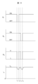
- 4 is a time chart showing an example of changes over time in control command signals (S 1 , S 2 ) to electrical contacts and an answerback signal (S 0 ).
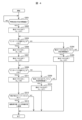
- 5 is a flowchart showing a processing operation of a safety controller in a fault diagnosis of an electrical contact in the embodiment.
- FIG. 1 is a schematic diagram of an elevator system according to one embodiment of the present invention.
- the elevator system includes a car 1, speed sensors (5, 6), an electric actuator 10, a drive mechanism (12-20), a lifting rod 21, and an emergency stop device 2.
- the speed sensor in this embodiment is provided on the car 1 and includes a rotation detector 6 and a roller 5 connected to the rotation shaft of the rotation detector 6.
- the roller 5 is connected to the rotation shaft of the rotation detector 6 so that the rotation shaft of the roller 5 and the rotation shaft of the rotation detector 6 are coaxial.
- a rotary encoder can be used as the rotation detector 6.
- the rollers 5 are in contact with the guide rails 4. Therefore, when the car 1 moves up and down, the rollers 5 rotate, causing the rotation detector 6 to rotate.
- a safety controller (described later) monitors the running speed of the car 1 based on the rotation position signal output by the rotation detector 6 as it rotates.
- an image sensor may be used as the speed sensor.
- the position and speed of the car 1 are detected based on image information of the surface condition of the guide rail 4 acquired by the image sensor. For example, the speed is calculated from the moving distance of the image feature in a given time.
- the electric actuator 10 is an electromagnetic actuator, and is placed on top of the car 1.
- the electromagnetic actuator has a movable piece or movable rod that is operated by, for example, a solenoid or electromagnet.
- the electric actuator 10 operates when a predetermined overspeed state of the car 1 is detected by the speed sensor (5, 6). At this time, the lifting rod 21 is pulled up by the drive mechanism (12-20) that is mechanically connected to the operating lever 11. This causes the emergency stop device 2 to enter a braking state.
- the drive mechanisms (12 to 20) will be described later.
- the emergency stop devices 2 are arranged on the left and right sides of the car 1.
- a pair of wedge-shaped brakes (not shown) provided on each emergency stop device 2 are movable between a braking position and a non-braking position, and clamp the guide rail 4 in the braking position. Furthermore, when the brakes rise relative to the car 1 as the car 1 descends, a braking force is generated by the frictional force acting between the brakes and the guide rail 4. As a result, the emergency stop devices 2 are activated when the car 1 falls into an overspeed state, bringing the car 1 to an emergency stop.
- the elevator system of this embodiment is equipped with a so-called ropeless governor system that does not use a governor rope, and when the ascent/descent speed of the car 1 exceeds the rated speed and reaches a first overspeed (e.g., a speed not exceeding 1.3 times the rated speed), the power supply to the drive device (hoist) and the power supply to the elevator controller that controls this drive device are cut off. Also, when the descent speed of the car 1 reaches a second overspeed (e.g., a speed not exceeding 1.4 times the rated speed), the electric actuator 10 provided on the car 1 is electrically operated, which activates the emergency stop device 2 and brings the car 1 to an emergency stop.
- a first overspeed e.g., a speed not exceeding 1.3 times the rated speed
- a second overspeed e.g., a speed not exceeding 1.4 times the rated speed
- the ropeless governor system is composed of the aforementioned speed sensors (5, 6) and a safety controller that determines whether the car 1 is in an overspeed state based on the output signal of the speed sensor.
- This safety controller measures the speed of the car 1 based on the output signal of the speed sensor, and when it determines that the measured speed has reached a first overspeed, it outputs a command signal to cut off the power supply to the drive device (hoist) and the power supply to the elevator controller that controls this drive device.
- the safety controller determines that the measured speed has reached a second overspeed, it outputs a command signal to operate the electric actuator 10.
- the safety controller is placed on top of the car 1 together with the electric operator 10.
- the drive mechanism (12-20) that drives the lifting rod 21 is described below.
- the operating lever 11 and first operating piece 16 of the electric actuator 10 are connected to form a roughly T-shaped first link member.
- the operating lever 11 and first operating piece 16 form the head and foot of the T, respectively.
- the roughly T-shaped first link member is rotatably supported on the crosshead 50 via the first operating shaft 19 at the connection between the operating lever 11 and the first operating piece 16.
- One end of a pair of lifting rods 21 (on the left side in the figure) is connected to the end of the first operating piece 16, which forms the foot of the T, on the opposite side to the connection between the operating lever 11 and the first operating piece 16.
- the connecting piece 17 and the second operating piece 18 are connected to form a substantially T-shaped second link member.
- the connecting piece 17 and the second operating piece 18 form the head and foot of the T, respectively.
- the substantially T-shaped second link member is rotatably supported on the crosshead 50 via the second operating shaft 20 at the connection between the connecting piece 17 and the second operating piece 18.
- the other end (left side in the figure) of the pair of lifting rods 21 is connected to the end of the second operating piece 18, which forms the foot of the T, on the opposite side to the connection between the connecting piece 17 and the second operating piece 18.
- the drive shaft 12 slidably passes through a fixed part 14 fixed to the crosshead 50.
- the drive shaft 12 also passes through a pressing member 15, which is fixed to the drive shaft 12.
- the pressing member 15 is located on the second link member (connection piece 17, second operating piece 18) side of the fixed part 14.
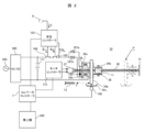
- FIG. 2 is a plan view showing the mechanism of the electric actuator 10 in this embodiment in the installed state shown in FIG. 1. Note that the mechanism of the electric actuator 10 shown in FIG. 2 is stored in the housing 30 in FIG. 1.
- FIG. 2 also shows the circuit configuration for driving and controlling the electric actuator 10.
- the emergency stop device 2 (FIG. 1) is in a non-braked state, and the electric actuator 10 is in a standby state. In other words, the elevator system is in a normal operating state.
- the mover has an attraction portion 34a that is attracted to the magnetic pole faces of the electromagnets 35a and 35b, and a support portion 34b that is fixed to the attraction portion 34a and to which the operating lever 11 is connected.
- the operating lever 11 is rotatably connected to the support portion 34b of the mover via a connection bracket 38.
- a mover detection switch 109 is provided at the position where the attraction portion 34a of the mover is located during standby.
- the movable member further has a cam portion 34c fixed to the suction portion 34a.
- the movable member detection switch 109 is operated by the cam portion 34c.
- the movable member detection switch 109 is operated by the cam portion 34c, it transitions from an on state to an off state, or from an off state to an on state. Therefore, it is possible to detect whether or not the movable member is located at the standby position according to the state of the movable member detection switch 109.
- the safety controller 103 determines whether or not the movable member is located at the standby position based on the state of the movable member detection switch 109.
- the movable element detection switch 109 is in the ON state when it is operated by the cam portion 34c.
- At least the attraction portion 34a of the mover (34a, 34b, 34c) is made of a magnetic material.
- a soft magnetic material such as low carbon steel or permalloy (iron-nickel alloy) is preferably used.
- Electromagnets 35a and 35b are excited by DC power supply 300.
- the excitation circuit for electromagnets 35a and 35b is configured as follows.
- One end of the coil of electromagnet 35a is connected to one end of the series connection of electrical contacts 104, 105 (electrical contact 105 side in FIG. 2) via fuse 107a.
- One end of the coil of electromagnet 35b is connected to one end of the series connection of electrical contacts 104, 105 (electrical contact 105 side in FIG. 2) via fuse 107b.
- the other end of the series connection of electrical contacts 104, 105 (electrical contact 104 side in FIG. 2) is connected to the high potential (positive terminal) of DC power supply 300.
- the other ends of the coils of electromagnets 35a and 35b are connected to each other and to the low potential (negative terminal) of DC power supply 300.
- the coils of electromagnets 35a, 35b are connected in parallel via fuses 107a, 107b.
- One end of the parallel connection is connected to the high potential (positive terminal) of DC power supply 300 via the series connection of electrical contacts 104, 105.
- the other end of the parallel connection is connected to the low potential (negative terminal) of DC power supply 300.
- a diode is connected as a protection circuit for suppressing surge voltage between the series connection point of electromagnet 35a and fuse 107a and the series connection point of electromagnet 35b and fuse 107b, i.e., between one end of the coil of electromagnet 35a and one end of the coil of electromagnet 35b.
- the forward direction of the diode is set to the direction in which a return current flows through each coil of electromagnets 35a and 35b due to the magnetic energy stored in each coil when the current flowing through electromagnets 35a and 35b is cut off by electrical contacts 104 and 105.
- Diodes may be connected to each coil. Diodes may also be connected between one end of the series connection of electrical contacts 104, 105 (the electrical contact 105 side in FIG. 2) and one end of the parallel connection of each coil of electromagnets 35a, 35b (the interconnection point of fuses 107a, 107b in FIG. 2). is connected to the high potential (positive terminal) of DC power supply 300 via the series connection of electrical contacts 104, 105. The other end of the parallel connection is connected to the low potential (negative terminal) of DC power supply 300.
- the protection circuit is not limited to a diode, and a snubber circuit or the like may also be used.
- the DC power supply 300 is composed of a rectifier and a power converter that converts AC power from the commercial single-phase AC power supply 200 into DC power.
- the commercial single-phase AC power supply 200 may be one phase of a commercial three-phase AC power supply that supplies power to the hoisting machine 400 and the elevator controller 7 that drives and controls the hoisting machine 400.
- DC power supply 300 serves as a power supply for operating electromagnets 35a and 35b as well as safety controller 103, rotation detector 6, and electrical contacts 104 and 105, and as a power supply for generating an answerback signal (S 0 ) described later.
- a battery 111 is connected to the output of the DC power supply 300 to compensate for the power supply to the load for a short period of time during a power outage or voltage drop. This maintains the supply of DC power in the event of a momentary power outage or momentary voltage drop in the commercial single-phase AC power supply 200.
- Fuses 107a and 107b are provided in the excitation circuit to protect electromagnets 35a and 35b from overcurrent, respectively.
- the electrical contacts 104, 105 are controlled to be turned on and off by the safety controller 103.
- the safety controller 103 controls each of the electrical contacts 104, 105 to be in the on state. This causes the coils of the electromagnets 35a, 35b to be energized, causing the electromagnets 35a, 35b to generate electromagnetic force.
- Each of the electrical contacts 104, 105 is composed of a normally open contact provided in, for example, an electromagnetic relay, an electromagnetic contactor, an electromagnetic switch, etc.
- a normally open contact provided in, for example, an electromagnetic relay, an electromagnetic contactor, an electromagnetic switch, etc.
- multiple electrical contacts are connected in series, so that even if an ON failure occurs in one contact when multiple electrical contacts are controlled to the OFF state to operate the emergency stop device 2 as described below, the flow of electricity to the electromagnets is cut off. This improves the reliability of the operation of the electric actuator 10. Note that an ON failure occurs, for example, due to welding of the contacts.
- An answerback signal S0 from the excitation circuit which is input to safety controller 103 via the signal line shown in FIG. 2, indicates the potential of one end of the parallel connection of each coil of electromagnets 35 a, 35 b, which is connected to the high potential (positive terminal) of DC power supply 300 via the series connection of electrical contacts 104, 105.
- the safety controller 103 detects the energized state of the electromagnets 35a, 35b and detects a failure of the electrical contacts 104, 105.
- the safety controller 103 When the safety controller 103 detects a predetermined overspeed state (the above-mentioned second overspeed) of the car 1 based on the rotation position signal S from the rotation detector 6, it outputs an OFF command to each of the electrical contacts 104, 105.
- the OFF command causes the electrical contacts 104, 105 to transition from the ON state (Fig. 2) to the OFF state.
- the excitation of the electromagnets 35a, 35b is stopped, and the electromagnetic force acting on the mover (34a, 34b, 34c) disappears.
- the constraint on the mover caused by the attraction of the attraction portion 34a of the mover to the electromagnets 35a, 35b is released, and the mover moves from the position in the standby state (Fig. 2) in the direction of the force of the drive spring 13 (to the right in the figure) to position P by the force of the drive spring 13 (F in Fig. 2).
- the drive shaft 12 is driven by the biasing force of the drive spring 13 (Fig. 1) in the direction from the fixed part 14 (Fig. 1) to the pressing member (Fig. 1) received by the pressing member 15 (Fig. 1) of the drive shaft 12.
- the first link member (operating lever 11 and first operating piece 16: Fig. 1) connected to the drive shaft 12 rotates around the first operating shaft 19 (Fig. 1).
- the second link member (connecting piece 17 and second operating piece 18: Fig. 1) connected to the drive shaft 12 rotates around the second operating shaft 20 (Fig. 1). This causes the lifting rod 21 (Fig. 1) connected to the second operating piece 18 to be pulled up.
- the movable members (34a, 34b, 34c) are returned from the moving position (position P in FIG. 2) to the standby position (FIG. 2) by the mechanical parts (36, 37, 39, 41) and the electrical equipment part (37, 112), the explanation of which is omitted, as described below.
- the electric actuator 10 has a feed screw 36 for driving the mover.
- the feed screw 36 is coaxially connected to the rotating shaft of the motor 37 and rotatably supported by a support member 41.
- the electromagnets 35a, 35b are fixed to an electromagnet support plate 39 that includes a feed nut portion (not shown).
- the feed nut portion of the electromagnet support plate 39 is screwed into the feed screw 36.
- the feed screw 36 is rotated by the motor 37.
- the motor 37 is driven by a motor controller 112.
- the motor controller 112 has a drive circuit for the motor 37 and controls the rotation of the motor 37 in response to a control command from the elevator controller 7.
- the motor 37 may be either a DC motor or an AC motor.
- the elevator controller 7 controls the operation of the car 1 and has information about the operating state of the elevator device. In this embodiment, as described above, the elevator controller 7 also has the function of controlling the motor 37 provided in the electric actuator 10.
- the elevator controller 7 includes a power conversion device such as an inverter device that drives the electric motor provided in the hoisting machine 400, a control unit that controls the electric motor by controlling the power conversion device, a DC power supply for a brake device provided in the hoisting machine 400, and a control unit that controls the opening and closing of the brake device.
- AC power is supplied to the elevator controller 7 from a commercial three-phase AC power supply via normally open contacts provided in an electromagnetic contactor, an electromagnetic switch, etc. Normally, the normally open contacts are closed.
- the safety controller 103 determines that the speed of the car 1 has reached the first overspeed described above, it outputs a command signal Sc, which instructs an electromagnetic contactor or electromagnetic switch to open the normally open contact. This cuts off the power supply from the commercial three-phase AC power source to the elevator controller 7, stopping the drive control of the motor 201 and putting the brake device 202 into a braking state. This brings the car 1 to an emergency stop.
- the recovery operation of the electric actuator 10 is performed when the elevator system is restored after the car 1 comes to an emergency stop due to the operation of the emergency stop device 2 or the occurrence of a power outage.
- the elevator controller 7 When returning the electric actuator 10 to the standby state, the elevator controller 7 sends a command to the motor controller 112 to rotate the motor 37.
- the motor controller 112 drives the motor 37 to rotate the feed screw 36.
- the rotating feed screw 36 and the feed nut portion of the electromagnet support plate 39 convert the rotation of the motor 37 into linear movement of the electromagnets 35a, 35b along the axial direction of the feed screw 36.
- the electromagnets 35a, 35b approach the movement position P of the mover (34a, 34b, 34c) and come into contact with the mover.
- the motor controller 112 monitors the motor current to control the motor 37. As described above, when the electromagnets 35a and 35b come into contact with the mover, the load on the motor 37 increases, and the motor current increases. When the motor current increases and exceeds a predetermined value, the motor controller 112 determines that the electromagnets 35a and 35b have come into contact with the mover. The motor controller 112 sends this determination result to the safety controller 103 and the elevator controller 7.
- the safety controller 103 When the safety controller 103 receives the determination result from the motor controller 112, it outputs an ON command signal as the control command signal S1 , S2 to each of the electrical contacts 104, 105.
- the ON command signal causes the electrical contacts 104, 105 to transition from the OFF state to the ON state.
- the electromagnets 35a, 35b are excited.
- the attracted portion 34a of the mover is attracted to the electromagnets 35a, 35b by the electromagnetic force generated by the excited electromagnets 35a, 35b.
- the elevator controller 7 When the elevator controller 7 receives the aforementioned judgment result from the motor controller 112, it sends a reverse command for the motor 37 to the motor controller 112. When the motor controller 112 receives the reverse command, it reverses the rotation direction of the motor 37, and reverses the feed screw 36. As a result, the movable element attracted to the electromagnets 35a and 35b moves toward the standby position ( Figure 2) together with the electromagnets 35a and 35b while receiving the biasing force of the drive spring 13.
- the cam portion 34c of the movable member (34a, 34b, 34c) is away from the movable member detection switch 109 from when the electric actuator 10 is actuated and the movable member (34a, 34b, 34c) moves to position P until just before the electric actuator 10 completes its return operation. Therefore, at this time, the movable member detection switch 109 is in the OFF state.
- the movable piece detection switch 109 When the movable piece (34a, 34b, 34c) attracted to the electromagnets 35a, 35b reaches the waiting position from position P, the movable piece detection switch 109 is operated by the cam portion 34c of the movable piece. When the movable piece detection switch 109 is operated, the elevator controller 7 determines that the movable piece is located at the waiting position. Based on this determination result, the elevator controller 7 sends a stop command for the motor 37 to the motor controller 112. When the motor controller 112 receives the stop command, it stops the rotation of the motor 37.
- the electric actuator 10 operates by turning off the electrical contacts 104 and 105. Therefore, in this embodiment, in order to ensure the reliability of the operation of the electric actuator 10, the safety controller 103 has a function to diagnose failures in the electrical contacts 104 and 105, as described below.
- the safety controller 103 diagnoses whether or not there is a malfunction in the electrical contacts 104, 105 when the elevator system is in operation and the car 1 is stopped, i.e., when the electric actuator 10 is in a standby state ( Figure 2).
- safety controller 103 transitions one of control command signals S1 , S2 to electrical contacts 104, 105 from an ON command signal to an OFF command signal. At this time, safety controller 103 maintains the other of control command signals S1 , S2 as an ON command signal.
- safety controller 103 determines that the electrical contact that provided the OFF command signal is normal. Also, if answerback signal S0 indicates a high potential, safety controller 103 determines that the electrical contact that provided the OFF command signal has an ON failure.
- safety controller 103 transitions the control command signal of the electrical contact diagnosed as having a fault, out of control command signals S1 , S2 to electrical contacts 104, 105, from an OFF command signal to an ON command signal, and transitions the control command signal to the electrical contact to be diagnosed as having a fault next from an ON command signal to an OFF command signal. Note that safety controller 103 transitions the control command signal to the electrical contact to be diagnosed as having a fault next from an ON command signal to an OFF command signal within a period in which the magnitude of the circulating current flowing through each coil of electromagnets 35a, 35b becomes large enough for electromagnets 35a, 35b to attract the movable element of electric actuator 10.
- the safety controller 103 determines that the electrical contact that provided the OFF command signal is normal. Also, if the answerback signal S0 indicates a high potential, the safety controller 103 determines that the electrical contact that provided the OFF command signal has an ON fault. After diagnosing the fault, the safety controller 103 transitions the control command signal to the electrical contact diagnosed as faulty from an OFF command signal to an ON command signal within a period in which the value of the circulating current flowing through each coil of the electromagnets 35a, 35b becomes large enough for the electromagnets 35a, 35b to attract the movable element of the electric actuator 10.
- the electric actuator 10 diagnoses whether or not each electrical contact has a fault while remaining in its standby state.
- FIG. 3 is a time chart showing an example of the change over time of the control command signals ( S1 , S2 ) to the electrical contacts and the answerback signal ( S0 ) when diagnosing the electrical contacts.
- a waveform diagram showing the change over time of the current ( iC ) flowing through the coil of the electromagnet is also shown.
- the safety controller 103 first diagnoses whether electrical contact 104 has a fault, and then diagnoses whether electrical contact 105 has a fault ( Figure 2).
- safety controller 103 transitions control command signal S1 to electrical contact 104 from an ON command signal (ON) to an OFF command signal (OFF).
- the answerback signal S0 transitions from a high level H (high potential) to a low level L (low potential) as shown by the solid line in the figure. If an ON failure occurs in the electrical contact 104, the answerback signal S0 is maintained at a high level H (high potential) as shown by the two-dot chain line in the figure.
- safety controller 103 transitions S1 from OFF to ON. During the period from t1 to t2 , safety controller 103 diagnoses the presence or absence of a fault in electrical contact 104 based on S0 .
- the predetermined time from t1 to t2 is set to a period during which the magnitude of the circulating current flowing through each coil of the electromagnets 35a, 35b is large enough for the electromagnets 35a, 35b to attract the movable piece of the electric actuator 10. For this reason, when the electrical contacts 104 are normal, the current iC flowing through the coil attenuates from the excitation current value Im during the period from t1 to t2 , but the attracted state between the electromagnets 35a, 35b and the movable piece of the electric actuator 10 is maintained.
- the safety controller 103 transitions the control command signal S2 to the electrical contact 105 from an ON command signal (ON) to an OFF command signal (OFF) at time t3 , a predetermined time after transition of S1 from OFF to ON at time t2 .
- the predetermined time from t2 to t3 is set to the time required for iC to return to Im when the electrical contact 104 is normal.
- S0 is at high level H.
- S0 transitions from high level H to low level L, as shown by the solid line in the figure. If an on-failure occurs in the electrical contact 105, S0 is maintained at high level H, as shown by the two-dot chain line in the figure.
- safety controller 103 transitions S2 from OFF to ON. During the period from t3 to t4 , safety controller 103 diagnoses the presence or absence of a fault in electrical contact 105 based on S0 .
- the predetermined time from t3 to t4 is set to a period during which the magnitude of the circulating current flowing through each coil of the electromagnets 35a, 35b is large enough for the electromagnets 35a, 35b to attract the movable piece of the electric actuator 10. For this reason, when the electrical contacts 105 are normal, the current iC flowing through the coil attenuates from the excitation current value Im during the period from t3 to t4 , but the attracted state between the electromagnets 35a, 35b and the movable piece of the electric actuator 10 is maintained.
- Safety controller 103 transitions S2 from OFF to ON at time t4 , thereby completing one fault diagnosis.
- FIG. 4 is a flowchart showing the processing operation of the safety controller in the fault diagnosis of electrical contacts in this embodiment. The explanation will be given with reference to FIG. 2 as appropriate.
- the safety controller 103 in this embodiment is equipped with a computer system such as a microcomputer. This computer system executes a specific program, causing the safety controller 103 to perform fault diagnosis of the electrical contacts.
- step S301 it determines whether the car doors have been closed for a predetermined time (e.g., three minutes). In other words, the safety controller 103 determines whether the car is stopped without responding to a call.
- the safety controller 103 obtains information on the operating status of the elevator device from, for example, the elevator controller 7, and determines whether the doors have been closed for a predetermined time (e.g., three minutes) based on the obtained information.
- step S301 If the safety controller 103 determines that the door open state has not continued for the predetermined time (NO in step S301), it executes step S301 again. If the safety controller 103 determines that the door open state has continued for the predetermined time (YES in step S301), it next executes step S302.
- step S302 safety controller 103 provides an OFF command signal as control command signal S1 to electrical contact 104 in order to turn off electrical contact 104. After executing step S302, safety controller 103 then executes step S303.
- step S303 safety controller 103 determines whether answerback signal S0 is at a low level. If safety controller 103 determines that S0 is at a low level (YES in step S303), safety controller 103 next executes step S06. If safety controller 103 determines that S0 is at a high level, not at a low level (NO in step S303), safety controller 103 next executes step S304.
- step S304 safety controller 103 determines whether a predetermined time has elapsed since providing an OFF command signal as control command signal S1 to electrical contact 104 in order to turn off electrical contact 104.
- the predetermined time in step S304 is set according to the delay time of the response of electrical contact 104 to control command signal S1 .
- step S303 If the safety controller 103 determines that the predetermined time has not elapsed (NO in step S304), it executes step S303 again. If the safety controller 103 determines that the predetermined time has elapsed (YES in step S301), it next executes step S305.
- step S305 the safety controller 103 determines that the electrical contact 104 has an ON failure, and provides an OFF command signal as the control command signal S2 to the electrical contact 105 to turn off the electrical contact 105. This causes the electric operating device 10 to operate, the stopped state of the car 1 is maintained, and the elevator apparatus enters a state of waiting for maintenance work.
- step S305 the safety controller 103 ends the series of processes.
- safety controller 103 determines in step S303 that answerback signal S0 is at a low level (YES in step S303), that is, when safety controller 103 determines that electrical contacts 104 are normal, then it executes step S306.
- safety controller 103 provides an ON command signal as control command signal S1 to electrical contact 104 in order to turn on electrical contact 104. After executing step S306, safety controller 103 then executes step S307.
- step S307 safety controller 103 provides an OFF command signal as control command signal S2 to electrical contact 105 in order to turn off electrical contact 105.
- safety controller 103 then executes step S308.
- safety controller 103 determines whether answerback signal S0 is at a low level. If safety controller 103 determines that S0 is at a low level (YES in step S308), safety controller 103 next executes step S311. If safety controller 103 determines that S0 is at a high level, not at a low level (NO in step S308), safety controller 103 next executes step S309.
- step S309 safety controller 103 determines whether a predetermined time has elapsed since providing an OFF command signal as control command signal S2 to electrical contact 105 in order to turn off electrical contact 105.
- the predetermined time in step S309 is set according to the delay time of the response of electrical contact 105 to control command signal S2 .
- step S308 If the safety controller 103 determines that the predetermined time has not elapsed (NO in step S309), it executes step S308 again. If the safety controller 103 determines that the predetermined time has elapsed (YES in step S309), it next executes step S310.
- step S310 the safety controller 103 determines that the electrical contact 105 has an ON failure, and provides an OFF command signal as the control command signal S1 to the electrical contact 104 to turn off the electrical contact 104. This causes the electric operator 10 to operate, the stopped state of the car 1 is maintained, and the elevator apparatus enters a state of waiting for maintenance work.
- step S310 the safety controller 103 executes step S310, it ends the series of processes.
- safety controller 103 determines in step S308 that answerback signal S0 is at a low level (YES in step S308), that is, when safety controller 103 determines that electrical contacts 105 are normal, then it executes step S311.
- step S311 safety controller 103 provides an ON command signal as control command signal S2 to electrical contact 105 in order to turn on electrical contact 105. After executing step S311, safety controller 103 then executes step S312.
- safety controller 103 determines whether movable element detection switch 109 is off. That is, safety controller 103 determines whether electric operator 10 has been actuated. For example, due to a variation in the delay time of the response of electrical contact 105 to control command signal S2 , even if an ON command signal is given to electrical contact 105, electric operator 10 may be actuated.
- step S312 If the safety controller 103 determines that the movable element detection switch 109 is off (YES in step S312), it then executes step 313. If the safety controller 103 determines that the movable element detection switch 109 is not off (NO in step S312), that is, if it determines that the electric actuator 10 is not operating, it ends the series of processes.
- step S313 the safety controller 103 returns the electric actuator 10 to the standby state as described above.
- step S313 When the safety controller 103 executes step S313, it ends the series of processes.
- the safety controller issues an OFF command signal to the electrical contact to be diagnosed in order to diagnose a fault in the electrical contact, and when the electrical contact is normally turned OFF, a current flows through the coil due to the magnetic energy stored in the coil of the electromagnet.
- the present invention is not limited to the above-described embodiments, but includes various modifications.
- the above-described embodiments have been described in detail to clearly explain the present invention, and the present invention is not necessarily limited to those having all of the configurations described.
- a single electrical contact may be sufficient.
- an excitation current from a DC power supply may be used as the answerback signal from the excitation circuit.
- the excitation current is detected by a current sensor, and when the excitation current is detected, the safety controller determines that the electrical contact has an ON failure. Also, when the current detection value is zero, the safety controller determines that the electrical contact is normal.
- movable element detection switch 109 instead of the movable element detection switch 109, other position detection sensors, such as a photoelectric position sensor, a magnetic position sensor, or a proximity sensor (capacitive or inductive), may be used.
- position detection sensors such as a photoelectric position sensor, a magnetic position sensor, or a proximity sensor (capacitive or inductive) may be used.
- the electric actuator 10 may be provided not only at the top of the car 1, but also at the bottom or side.
- the elevator system may have a machine room, or it may be a so-called machine room-less elevator that does not have a machine room.
Landscapes
- Engineering & Computer Science (AREA)
- Mechanical Engineering (AREA)
- Elevator Control (AREA)
- Maintenance And Inspection Apparatuses For Elevators (AREA)
Abstract
La présente invention divulgue un appareil d'ascenseur comprenant un appareil d'arrêt d'urgence qui est actionné par un dispositif d'actionnement électrique dans lequel le nombre de contacts électriques peut être réduit tout en rendant la détection de défaillance de contacts électriques possible. Dans l'appareil d'ascenseur, lorsqu'un dispositif de commande (103) éteint des contacts électriques (104, 105) et que des électroaimants (35a, 35b) sont démagnétisés, un dispositif d'actionnement électrique (10) fonctionne. Le dispositif de commande fournit une instruction d'arrêt (S1, S2) aux contacts électriques et détermine si les contacts électriques ont été éteints, ce qui permet de diagnostiquer la présence ou l'absence d'une défaillance dans les contacts électriques. Lorsque le dispositif de commande diagnostique la présence ou l'absence d'une défaillance et que les contacts électriques sont éteints, l'énergie magnétique accumulée dans la bobine des électroaimants provoque la circulation d'un courant dans la bobine.
Priority Applications (3)
| Application Number | Priority Date | Filing Date | Title |
|---|---|---|---|
| PCT/JP2023/021309 WO2024252606A1 (fr) | 2023-06-08 | 2023-06-08 | Appareil d'ascenseur |
| CN202380098364.5A CN121127433A (zh) | 2023-06-08 | 2023-06-08 | 电梯装置 |
| JP2025525567A JPWO2024252606A1 (fr) | 2023-06-08 | 2023-06-08 |
Applications Claiming Priority (1)
| Application Number | Priority Date | Filing Date | Title |
|---|---|---|---|
| PCT/JP2023/021309 WO2024252606A1 (fr) | 2023-06-08 | 2023-06-08 | Appareil d'ascenseur |
Publications (1)
| Publication Number | Publication Date |
|---|---|
| WO2024252606A1 true WO2024252606A1 (fr) | 2024-12-12 |
Family
ID=93795623
Family Applications (1)
| Application Number | Title | Priority Date | Filing Date |
|---|---|---|---|
| PCT/JP2023/021309 Ceased WO2024252606A1 (fr) | 2023-06-08 | 2023-06-08 | Appareil d'ascenseur |
Country Status (3)
| Country | Link |
|---|---|
| JP (1) | JPWO2024252606A1 (fr) |
| CN (1) | CN121127433A (fr) |
| WO (1) | WO2024252606A1 (fr) |
Citations (5)
| Publication number | Priority date | Publication date | Assignee | Title |
|---|---|---|---|---|
| JP2000247552A (ja) * | 1999-02-25 | 2000-09-12 | Mitsubishi Electric Corp | エレベーターのブレーキ制御装置 |
| WO2008090601A1 (fr) * | 2007-01-23 | 2008-07-31 | Mitsubishi Electric Corporation | Appareil ascenseur |
| US20180093855A1 (en) * | 2016-10-04 | 2018-04-05 | Kone Corporation | Elevator brake controller |
| WO2021149172A1 (fr) * | 2020-01-22 | 2021-07-29 | 株式会社日立製作所 | Dispositif de commande de frein d'ascenseur et dispositif ascenseur |
| WO2023058198A1 (fr) * | 2021-10-07 | 2023-04-13 | 株式会社日立製作所 | Dispositif de détection de défaut et procédé de détection de défaut pour actionneur électrique pour dispositif d'arrêt d'urgence |
-
2023
- 2023-06-08 JP JP2025525567A patent/JPWO2024252606A1/ja active Pending
- 2023-06-08 WO PCT/JP2023/021309 patent/WO2024252606A1/fr not_active Ceased
- 2023-06-08 CN CN202380098364.5A patent/CN121127433A/zh active Pending
Patent Citations (5)
| Publication number | Priority date | Publication date | Assignee | Title |
|---|---|---|---|---|
| JP2000247552A (ja) * | 1999-02-25 | 2000-09-12 | Mitsubishi Electric Corp | エレベーターのブレーキ制御装置 |
| WO2008090601A1 (fr) * | 2007-01-23 | 2008-07-31 | Mitsubishi Electric Corporation | Appareil ascenseur |
| US20180093855A1 (en) * | 2016-10-04 | 2018-04-05 | Kone Corporation | Elevator brake controller |
| WO2021149172A1 (fr) * | 2020-01-22 | 2021-07-29 | 株式会社日立製作所 | Dispositif de commande de frein d'ascenseur et dispositif ascenseur |
| WO2023058198A1 (fr) * | 2021-10-07 | 2023-04-13 | 株式会社日立製作所 | Dispositif de détection de défaut et procédé de détection de défaut pour actionneur électrique pour dispositif d'arrêt d'urgence |
Also Published As
| Publication number | Publication date |
|---|---|
| CN121127433A (zh) | 2025-12-12 |
| JPWO2024252606A1 (fr) | 2024-12-12 |
Similar Documents
| Publication | Publication Date | Title |
|---|---|---|
| JP7212201B2 (ja) | エレベータ装置 | |
| JP4722845B2 (ja) | エレベータ制御装置 | |
| CN100455501C (zh) | 电梯安全装置 | |
| JP7524487B2 (ja) | 非常止め装置用電動作動器の故障検出装置および故障検出方法 | |
| JP3629207B2 (ja) | エスカレータまたは動く歩道の制動方法ならびにエスカレータまたは動く歩道の制動装置 | |
| JP2011524319A (ja) | 低電力制御装置を用いたブレーキの安全な制御 | |
| CN101687610A (zh) | 电梯装置 | |
| JP7554945B2 (ja) | 非常止め装置用電動作動器の動作確認装置および動作確認方法 | |
| CN115720567B (zh) | 电梯设备 | |
| WO2025115097A1 (fr) | Appareil d'ascenseur et procédé de commande d'ascenseur | |
| WO2005092768A1 (fr) | Méthode d’excitation d’actionneur et circuit d’excitation d’actionneur | |
| US12492101B2 (en) | Elevator apparatus | |
| WO2024142155A1 (fr) | Appareil ascenseur | |
| JP5220126B2 (ja) | エレベータの安全回路装置 | |
| JP7575623B2 (ja) | 非常止め装置用電動作動器の点検装置 | |
| WO2025120747A1 (fr) | Dispositif d'ascenseur et procédé de commande pour dispositif d'ascenseur | |
| EP4549359A1 (fr) | Dispositif d'ascenseur | |
| WO2025120740A1 (fr) | Dispositif d'ascenseur et procédé de commande pour dispositif d'ascenseur | |
| CN121127433A (zh) | 电梯装置 | |
| WO2025238800A1 (fr) | Appareil d'ascenseur et procédé de commande d'appareil d'ascenseur | |
| JP2025104878A (ja) | エレベータの安全システム、並びにエレベータ | |
| KR100745928B1 (ko) | 엘리베이터 제어 장치 | |
| CN121404904A (zh) | 电梯控制系统、电梯以及电梯控制方法 |
Legal Events
| Date | Code | Title | Description |
|---|---|---|---|
| 121 | Ep: the epo has been informed by wipo that ep was designated in this application |
Ref document number: 23940015 Country of ref document: EP Kind code of ref document: A1 |
|
| ENP | Entry into the national phase |
Ref document number: 2025525567 Country of ref document: JP Kind code of ref document: A |
|
| NENP | Non-entry into the national phase |
Ref country code: DE |
|
| 122 | Ep: pct application non-entry in european phase |
Ref document number: 23940015 Country of ref document: EP Kind code of ref document: A1 |