WO2024252648A1 - Dispositif de traitement de liquides, dispositif d'extraction d'acides nucléiques et dispositif de test génique - Google Patents
Dispositif de traitement de liquides, dispositif d'extraction d'acides nucléiques et dispositif de test génique Download PDFInfo
- Publication number
- WO2024252648A1 WO2024252648A1 PCT/JP2023/021447 JP2023021447W WO2024252648A1 WO 2024252648 A1 WO2024252648 A1 WO 2024252648A1 JP 2023021447 W JP2023021447 W JP 2023021447W WO 2024252648 A1 WO2024252648 A1 WO 2024252648A1
- Authority
- WO
- WIPO (PCT)
- Prior art keywords
- constant temperature
- temperature
- thermal resistance
- heat transfer
- unit
- Prior art date
- Legal status (The legal status is an assumption and is not a legal conclusion. Google has not performed a legal analysis and makes no representation as to the accuracy of the status listed.)
- Ceased
Links
Images



Classifications
-
- C—CHEMISTRY; METALLURGY
- C12—BIOCHEMISTRY; BEER; SPIRITS; WINE; VINEGAR; MICROBIOLOGY; ENZYMOLOGY; MUTATION OR GENETIC ENGINEERING
- C12M—APPARATUS FOR ENZYMOLOGY OR MICROBIOLOGY; APPARATUS FOR CULTURING MICROORGANISMS FOR PRODUCING BIOMASS, FOR GROWING CELLS OR FOR OBTAINING FERMENTATION OR METABOLIC PRODUCTS, i.e. BIOREACTORS OR FERMENTERS
- C12M1/00—Apparatus for enzymology or microbiology
Definitions
- This disclosure relates to a liquid treatment device, a nucleic acid extraction device, and a genetic testing device.
- nucleic acids are amplified using methods such as PCR (polymerase chain reaction) and the like, and the nucleic acids contained in the sample are extracted before testing.
- nucleic acid extraction using the Magtration method which uses magnetic particles as carriers, nucleic acids are extracted through a liquid processing step that solubilizes proteins in the sample, a liquid processing step that bonds the magnetic particle carrier with the phosphate group of the nucleic acid, a liquid processing step that removes impurities from the magnetic particles to which the nucleic acid is bound, and a liquid processing step that elutes the nucleic acid from the magnetic particles.
- the optimal processing temperature differs depending on each liquid processing step, the type of sample, the type of reagent used, and the processing protocol. Therefore, in order to perform nucleic acid extraction for reliable genetic testing, a liquid processing device that can quickly change the temperature of the liquid depending on the content of the liquid processing is required.
- Patent Document 1 discloses a genetic testing device that includes heat sources provided individually for multiple test vessels that contain samples, and a control unit that controls the heat sources to individually adjust the temperature of the samples.
- Patent Document 2 discloses a laboratory thermostat equipped with at least two temperature control devices in thermally conductive contact with a temperature control block, which has a storage section for storing a container containing a liquid sample, in order to set different locations of the temperature control block to various temperatures.
- Patent Document 2 requires multiple temperature control devices to maintain different temperatures at different locations in a temperature control block that has multiple storage compartments for containers that hold liquid samples. Therefore, by installing multiple temperature control systems, the structure related to the temperature control systems becomes more complex and costs increase, which becomes an issue.
- the problem that this invention aims to solve is to provide a small-sized liquid treatment device that can use multiple thermostatic sections with optimal temperatures for liquid treatment without necessarily requiring multiple temperature control systems in a liquid treatment device that performs liquid treatment at multiple temperatures.
- the liquid treatment device of the present disclosure includes a constant temperature unit having a container holding unit that holds a liquid container containing liquid and a plurality of constant temperature regions with different set temperatures, a dispenser that aspirates or dispenses the liquid contained in the liquid container, a heat transfer unit that heats or cools the constant temperature unit, a temperature sensor unit that outputs data related to the temperature of the constant temperature unit, a power supply unit that supplies power to the heat transfer unit, a control unit that controls the power supplied by the power supply unit to the heat transfer unit based on the output of the temperature sensor unit, and a first thermal resistance unit that separates at least two constant temperature regions, the first thermal resistance unit having a thermal resistance value greater than that of the constant temperature unit and such that when the temperature of one constant temperature region separated by the first thermal resistance unit becomes the set temperature of the one constant temperature region, the temperature of another constant temperature region separated by the first thermal resistance unit becomes the set temperature of the other constant temperature region.
- the nucleic acid extraction device disclosed herein also includes the liquid treatment device described above.
- the genetic testing device disclosed herein also includes the liquid treatment device described above.
- the liquid treatment device can provide a compact liquid treatment device that performs liquid treatment at multiple temperatures and can utilize multiple thermostatic sections at optimal temperatures for liquid treatment without necessarily requiring multiple temperature control systems. This is expected to improve the throughput of liquid treatment, simplify the temperature control system, and reduce the costs associated with manufacturing the device. Furthermore, by miniaturizing the liquid treatment device, it becomes possible to use a multi-well plate as a liquid container, which is expected to reduce the labor required for replacing liquid containers and the risk of mix-ups.
- FIG. 1 is a schematic diagram showing a cross-sectional structure of a liquid treatment device according to a first embodiment.
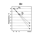
- FIG. 1 is a schematic diagram of the temperatures of the constant temperature region 6a, the constant temperature region 6b, the constant temperature region 6c, and the environment when a temperature sensor unit 11 is installed in the constant temperature region 6b in the liquid treatment device of Example 1.
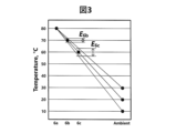
- FIG. 1 is a schematic diagram of the temperatures of the constant temperature region 6a, the constant temperature region 6b, the constant temperature region 6c, and the environment when a temperature sensor unit 11 is installed in the constant temperature region 6a in the liquid treatment device of Example 1.
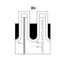
- FIG. 1 is a schematic diagram showing an example of the structure of first heat resistance portions 8a and 8b of the liquid treatment device of Example 1.
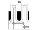
- FIG. 1 is a schematic diagram showing an example of the structure of first heat resistance portions 8a and 8b of the liquid treatment device of Example 1.
- FIG. 1 is a schematic diagram showing an example of the structure of first heat resistance portions 8a and 8b of the liquid treatment device of Example 1.
- FIG. 1 is a schematic diagram showing a cross-sectional structure of a liquid treatment device according to a second embodiment of the present invention
- FIG. 13 is a schematic diagram showing a cross-sectional structure of a liquid treatment device according to a third embodiment.
- FIG. 13 is a schematic diagram showing a cross-sectional structure of third heat resistance portions 15a and 15b of the liquid treatment device of Example 4.
- Figure 1 is a schematic diagram showing the cross-sectional structure of the liquid treatment device according to the first embodiment.
- a structure in which three constant temperature regions are set to different temperatures by one temperature control system will be described.
- the liquid 1 is contained in a liquid container 2 and dispensed by aspirating and discharging with a dispenser 3.
- the liquid processing device 4 includes the dispenser 3, a thermostatic unit 6 having a container holder 5 for holding the liquid container 2, a heat transfer unit 7, first thermal resistance units 8a and 8b, a heat dissipation unit 9, a thermal insulation unit 10, a temperature sensor unit 11, a control unit 12, and a power supply unit 13.
- the liquid container 2 has multiple regions for storing the liquid 1.
- the liquid container 2 may be one in which the regions for storing the liquid 1 are arranged in one direction, or a multi-well plate in which the regions are arranged in two directions. In this embodiment, a multi-well plate is used as the liquid container 2.
- the constant temperature section 6 is provided with a set temperature.
- the set temperature may be higher or lower than the ambient temperature.
- the constant temperature section 6 is divided into multiple regions with different set temperatures.
- the constant temperature section 6 is divided into three regions with different set temperatures, and each region is called the constant temperature region 6a, the constant temperature region 6b, and the constant temperature region 6c.
- the set temperatures of the constant temperature region 6a, the constant temperature region 6b, and the constant temperature region 6c are 80°C, 70°C, and 60°C, respectively.
- Each of the constant temperature regions 6a to 6c may hold one region of the container holding section 5, or multiple regions. It is desirable that each of the constant temperature regions 6a to 6c is made of a material with high thermal conductivity and excellent temperature uniformity.
- the constant temperature section 6 is made of, for example, copper, aluminum, or an alloy thereof. Additionally, all of the constant temperature regions 6a-6c may be made of the same material, or at least two of the constant temperature regions 6a-6c may be made of different materials.
- the heat transfer unit 7 heats or cools the constant temperature unit 6. If the set temperatures of the constant temperature areas 6a to 6c are higher than the ambient temperature, a heat generating component such as a heater can be used for the heat transfer unit 7. If the set temperatures of the constant temperature areas 6a to 6c are lower than the ambient temperature, the heat transfer unit 7 can be cooled by using a Peltier module, for example. In this embodiment, there are three constant temperature areas 6a to 6c with different set temperatures, while there is only one heat transfer unit 7. The heat transfer unit 7 is in contact with the constant temperature area 6a, whose set temperature is the furthest from the ambient temperature. The heat transfer unit 7 does not have to be in contact with the constant temperature area 6a, as long as it can heat or cool the constant temperature area 6a.
- the first thermal resistance portion 8a separates the constant temperature region 6a and the constant temperature region 6b, which have different set temperatures
- the first thermal resistance portion 8b separates the constant temperature region 6b and the constant temperature region 6c, which have different set temperatures.
- the first thermal resistance portions 8a and 8b adjust the amount of heat transfer from the higher set temperature to the lower set temperature of the two separated constant temperature regions, and are provided with a thermal resistance value required for the temperatures of both constant temperature regions to reach the set temperature.
- the first thermal resistance portion 8a has a thermal resistance value such that when the constant temperature region 6a has a set temperature of 80°C due to heating by the heat transfer portion 7, the constant temperature region 6b has a set temperature of 70°C.
- the first thermal resistance portion 8b has a thermal resistance value such that when the constant temperature region 6b has a set temperature of 70°C due to heat transfer via the first thermal resistance portion 8a, the constant temperature region 6c has a set temperature of 60°C.
- the heat dissipation unit 9 can be provided in the constant temperature area 6b or 6c other than the constant temperature area 6a, whose set temperature is the furthest from the ambient temperature.
- the heat dissipation unit 9 is provided in the constant temperature area 6c, whose set temperature is the closest to the ambient temperature among the constant temperature areas 6a to 6c.
- a cooling fin is used for the heat dissipation unit 9.
- the heat dissipation unit 9 has the thermal resistance values of the first thermal resistance unit 8a and the first thermal resistance unit 8b, as well as the heat dissipation performance that allows the constant temperature areas 6a, 6b, and 6c to reach their respective set temperatures.
- the thermal resistance values of the first thermal resistance portion 8a and the first thermal resistance portion 8b In order to provide a large temperature difference between the constant temperature regions 6a, 6b, and 6c, it is necessary to increase the thermal resistance values of the first thermal resistance portion 8a and the first thermal resistance portion 8b. In order to increase the thermal resistance value, it is necessary to reduce the apparent thermal conductivity of the first thermal resistance portion 8a and the first thermal resistance portion 8b or to increase the thickness. In the case where a multi-well plate is used as the liquid container 2 and the distance between the container holding portions 5 is determined by the dimensions of the multi-well plate as in this embodiment, it is difficult to freely change the thickness of the first thermal resistance portion 8a and the first thermal resistance portion 8b, and it may not be possible to provide a set temperature difference between the constant temperature regions 6a, 6b, and 6c.
- the temperatures of the constant temperature regions 6b and 6c can be brought closer to the environmental temperature. Then, when the constant temperature region 6a is at the set temperature, it becomes easier to increase the temperature difference between the constant temperature regions 6a, 6b, and 6c.
- the heat dissipation section 9 is provided in the constant temperature region 6c, but the heat dissipation section 9 may be provided in the constant temperature region 6b and the constant temperature region 6c.
- the heat dissipation performance of the heat dissipation section 9 provided in the constant temperature region 6b and the heat dissipation performance of the heat dissipation section 9 provided in the constant temperature region 6c may be the same or different.
- the heat insulating section 10 is configured to cover the constant temperature section 6, the heat transfer section 7, and the first thermal resistance sections 8a and 8b. This allows the constant temperature section 6 to maintain temperature uniformity. In addition, by suppressing heat dissipation to the environment, the energy consumption of the heat transfer section 7 can be kept low.
- the temperature sensor unit 11 measures the temperature of the constant temperature unit 6 and outputs data related to the temperature of the constant temperature unit 6 to the control unit 12.
- the control unit 12 controls the power supplied to the heat transfer unit 7 by the power supply unit 13 based on the output of the temperature sensor unit 11 so that the temperature of the constant temperature area 6b in which the temperature sensor unit 11 is installed becomes the set temperature.
- the temperature sensor unit 11 is installed in the constant temperature area 6b, which has an intermediate set temperature among the constant temperature areas 6a to 6c, and the power supplied to the heat transfer unit 7 is controlled so that the constant temperature area 6b becomes the set temperature of 70°C.
- the constant temperature area in which the temperature sensor unit 11 is installed may be the constant temperature area 6a or the constant temperature area 6c.
- FIG. 2 shows a schematic diagram of the temperatures of constant temperature area 6a, constant temperature area 6b, constant temperature area 6c, and the environment (ambient).
- the constant temperature area 6a, constant temperature area 6b, and constant temperature area 6c are configured to have set temperatures of 80°C, 70°C, and 60°C, respectively, when the environmental temperature is 20°C.
- constant temperature area 6b is controlled to a set temperature of 70°C even if the environmental temperature varies.
- the temperatures of constant temperature area 6a and constant temperature area 6c vary from the set temperature due to the variation in the environmental temperature. If the degree of temperature variation in constant temperature area 6a and constant temperature area 6c is E_6a and E_6c, respectively, E_6a and E_6c will be approximately the same as shown in Figure 2.
- FIG. 1 shows a schematic diagram of the temperatures of the constant temperature areas 6a, 6b, 6c, and (Ambient) at this time.
- the constant temperature area 6a is controlled to the set temperature by the action of the temperature sensor unit 11, even if the ambient temperature varies.
- the temperatures of the constant temperature areas 6b and 6c vary from the set temperature due to the variation in the ambient temperature. If the degree of variation in temperature of the constant temperature areas 6b and 6c is E_6b and E_6c, respectively, it can be seen that E_6c is larger than E_6b, as shown in Figure 3.
- the temperature sensor unit 11 In order to prevent any of the three constant temperature regions 6a-6c from deviating significantly from the set temperature when the environmental temperature changes, it is effective to install the temperature sensor unit 11 in the constant temperature region 6b, which has an intermediate set temperature. On the other hand, when it is necessary to control the temperature of any of the three constant temperature regions 6a-6c with high accuracy as a priority, it is effective to install the temperature sensor unit 11 in that constant temperature region.
- the above measures are effective in preventing environmental temperature variations from reducing temperature controllability for liquid processing in a configuration with a small number of temperature control systems compared to the number of constant temperature regions 6a-6c with different set temperatures.
- the control unit 12 may correct the power supplied by the power supply unit 13 to the heat transfer unit 7 so that the temperature of the constant temperature region where the liquid treatment is performed becomes the set temperature. For example, when performing liquid treatment in the constant temperature region 6c with a set temperature of 60°C, the control unit 12 controls the power supply unit 13 to supply to the heat transfer unit 7 the power required for the constant temperature region 6c to reach the set temperature of 60°C.
- the control unit 12 may correct the power supply unit 13 to supply to the heat transfer unit 7 the power required for the constant temperature region 6a to reach the set temperature of 80°C.
- the amount of power supply required for each constant temperature region to reach the set temperature can be measured and recorded in advance.
- the environmental temperature may be measured by a temperature sensor not shown, and the amount of power supply required for a certain constant temperature unit 6 to reach the set temperature may be recorded for each environmental temperature.
- the temperatures of the constant temperature areas 6a to 6c, which have different set temperatures are close to their respective set temperatures, so it is expected that the temperature of the constant temperature unit 6 can be brought closer to the set temperature in a short temperature change time.
- the first thermal resistance parts 8a and 8b adjust the amount of heat transfer from the higher set temperature to the lower set temperature of the two separated constant temperature areas, and are provided with a thermal resistance value required for the temperatures of both constant temperature areas to reach the set temperature.
- An example of the structure of the first thermal resistance parts 8a and 8b is shown in Figure 4.
- a single thermal resistance member 801 may be used to provide the desired thermal resistance value.
- a uniform solid material with a lower thermal conductivity than the constant temperature part 6 can be selected and arranged as the thermal resistance member 801. From the viewpoint of creating a temperature difference between the separated constant temperature areas, a solid material with a lower thermal conductivity than the constant temperature part 6 is desirable.
- thermo resistance member 801 a resin-based material, a rubber-based material, or a heat insulating material is used.
- a gas layer may be used as the thermal resistance member 801.
- Both of the first thermal resistance portions 8a and 8b may be a single thermal resistance member 801, or either of the first thermal resistance portions 8a or 8b may be a single thermal resistance member 801.
- a desired thermal resistance value may be provided by a convex part 802 and a concave part 803 provided on the surface of the constant temperature region.
- the contact area between the convex part 802 provided on the surface of one constant temperature region and the surface of the other constant temperature region is changed, and the solid conduction heat transfer by the convex part 802 can be adjusted to provide a desired thermal resistance value.
- the concave part 803 may be a solid material with an appropriate thermal conductivity or a gas layer, as in the thermal resistance member 801.
- the constant temperature part 6 may be an integrated part, and a hole may be machined at a location corresponding to the concave part 803 to form a structure corresponding to the convex part 802 and the concave part 803.
- Both the first thermal resistance parts 8a and 8b may have a structure having the convex part 802 and the concave part 803, or either one of the first thermal resistance parts 8a or 8b may have a structure having the convex part 802 and the concave part 803.
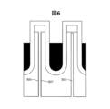
- FIG. 5 Another example of the structure of the first thermal resistance parts 8a and 8b is shown in FIG. 5.
- a desired thermal resistance value may be provided by a spacer 804 and a fastening member 805.
- the spacer 804 and the fastening member 805 can fix the separated constant temperature areas in a predetermined relative positional relationship, and can also be given the role of adjusting solid conduction heat transfer.
- the size of the spacer 804 may be changed to change the heat transfer area, the number of spacers 804 arranged may be changed to change the heat transfer area, or a material with a different thermal conductivity may be used for the spacer 804.
- a resin washer with low thermal conductivity may be used for the spacer 804.
- a material with a different thermal conductivity may be used for the fastening member 805.
- a resin screw may be used for the fastening member 805.
- Both of the first thermal resistance parts 8a and 8b may have a structure including a spacer 804 and a fastening member 805, or either one of the first thermal resistance parts 8a or 8b may have a structure including a spacer 804 and a fastening member 805.
- the spacer 804 used as the first thermal resistance part 8a and the spacer 804 used as the first thermal resistance part 8b may be fixed with one fastening member 805.
- the desired thermal resistance value may be provided by a heat radiation part 806 and a heat radiation part 807 provided on the opposing surfaces of the constant temperature area.
- the desired thermal resistance value is provided by adjusting the radiation heat transfer between the surfaces of the constant temperature area.
- the heat radiation part 806 or the heat radiation part 807 may be subjected to a surface treatment that changes the emissivity.
- the heat radiation part 806 or the heat radiation part 807 may be made of a radiative paint or may be formed with an oxide coating such as anodized aluminum.
- the radiation heat transfer may be adjusted depending on the area to which the surface treatment is applied to provide the desired thermal resistance value.
- the heat radiation part 806 and the heat radiation part 807 are formed on both opposing surfaces of the constant temperature area, but a heat radiation part may be provided on only one surface.
- both of the first thermal resistance parts 8a and 8b may have a structure including a heat radiation part 806 or 807, or either one of the first thermal resistance parts 8a or 8b may have a structure including a heat radiation part 806 or 807.
- a sealed part 808 may be formed and the internal space of the sealed part 808 may be depressurized to have a desired thermal resistance value. If the sealed part 808 is not depressurized, heat transfer occurs due to air convection, conductive heat transfer, and radiative heat transfer between surfaces in the constant temperature region. By depressurizing the sealed part 808, the effects of air convection and conductive heat transfer may be reduced to have a desired thermal resistance value. Also, a heat insulating material that has been depressurized and sealed in advance, such as a vacuum insulation panel, may be used. Both of the first thermal resistance parts 8a and 8b may have a structure having a sealed part 808, or either one of the first thermal resistance parts 8a or 8b may have a structure having a sealed part 808.
- the thermal resistance value of the first thermal resistance parts 8a and 8b can be easily changed by using the above structure. Even if it becomes necessary to change the set temperature of the constant temperature areas 6a to 6c, it is possible to realize the constant temperature areas 6a to 6c with different set temperatures in a short period of time by changing the thermal resistance value using the above structure, without making major changes to the overall structure.
- Each of the first thermal resistance parts 8a and 8b may be configured by selecting one of the structures above, or may be configured by combining multiple structures.
- the temperatures of the multiple constant temperature areas 6a-6c can be set to different set temperatures by a single temperature control system consisting of the heat transfer section 7, temperature sensor section 11, control section 12, and power supply section 13.
- a single temperature control system consisting of the heat transfer section 7, temperature sensor section 11, control section 12, and power supply section 13.
- the constant temperature areas 6a-6c with different set temperatures are prepared, so there is no need to wait for the temperature of the constant temperature section to rise or fall, and the constant temperature areas 6a-6c with different optimal temperatures depending on the liquid treatment can be immediately used, which is expected to improve the throughput of liquid treatment.
- the control system can be simplified, which is expected to reduce the costs associated with manufacturing the device.
- the structure that adjusts the heat transfer between constant temperature regions 6a to 6c via first thermal resistance portions 8a and 8b allows the entire liquid treatment device to be constructed in a compact size. This makes it possible to use a multi-well plate as the liquid container, which is expected to reduce the labor required for replacing liquid containers and the risk of mix-ups.
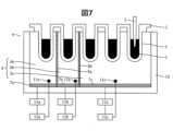
- FIG. 7 is a schematic diagram showing the cross-sectional structure of the liquid treatment device according to the second embodiment.
- a structure in which three constant temperature regions are set to different temperatures by multiple temperature control systems will be described. Explanations of elements that overlap with those in the first embodiment will be omitted as appropriate.
- the heat transfer unit 7 heats or cools the constant temperature unit 6. If the set temperatures of the constant temperature areas 6a to 6c are higher than the ambient temperature, a heat generating component such as a heater can be used in the heat transfer unit 7. If the set temperatures of the constant temperature areas 6a to 6c are lower than the ambient temperature, the heat transfer unit 7 can be cooled, for example, by using a Peltier module. In this embodiment, the constant temperature areas 6a, 6b, and 6c, which have different set temperatures, are heated or cooled by the heat transfer units 7a, 7b, and 7c, respectively.
- temperature sensor unit 11a, temperature sensor unit 11b, temperature sensor unit 11c are installed in constant temperature area 6a, constant temperature area 6b, constant temperature area 6c, respectively.
- Each temperature sensor unit 11a, temperature sensor unit 11b, temperature sensor unit 11c measures the temperature of constant temperature area 6a, constant temperature area 6b, constant temperature area 6c, respectively.
- the measurement results by temperature sensor unit 11a, temperature sensor unit 11b, temperature sensor unit 11c are input to control unit 12a, control unit 12b, control unit 12c, respectively.
- Control unit 12a, control unit 12b, control unit 12c control the power supplied by power supply unit 13a, power supply unit 13b, power supply unit 13c to heat transfer unit 7a, heat transfer unit 7b, heat transfer unit 7c, respectively, so that the temperatures of constant temperature area 6a, constant temperature area 6b, constant temperature area 6c become the respective set temperatures.
- a temperature control system consisting of a heat transfer unit 7a, a temperature sensor unit 11a, a control unit 12a, and a power supply unit 13a is provided for the constant temperature region 6a
- a temperature control system consisting of a heat transfer unit 7b, a temperature sensor unit 11b, a control unit 12b, and a power supply unit 13b is provided for the constant temperature region 6b
- a temperature control system consisting of a heat transfer unit 7c, a temperature sensor unit 11c, a control unit 12c, and a power supply unit 13c is provided for the constant temperature region 6c.
- a single controller having a processor and memory may execute the functions of the control unit 12a, the control unit 12b, and the control unit 12c.
- the structure may have multiple temperature control systems, each consisting of a heat transfer unit, a temperature sensor unit, a control unit, and a power supply unit, for each of the multiple constant temperature areas 6a to 6c with different set temperatures.
- a structure is shown in which the same number of temperature control systems are provided for the three constant temperature areas 6a to 6c with different set temperatures. This configuration is not limited to this, and the number of temperature control systems may be one or more and may be less than the number of constant temperature areas 6a to 6c with different set temperatures.
- a structure with one temperature control system corresponds to Example 1.
- the multiple temperature control systems can set the temperatures of the multiple constant temperature areas 6a-6c to different set temperatures.
- the liquid treatment device 4 of this embodiment multiple constant temperature areas 6a-6c with different set temperatures are prepared, so there is no need to wait for the temperature of the constant temperature section to rise or fall, and the constant temperature areas 6a-6c with different optimal temperatures depending on the liquid treatment can be immediately used, which is expected to improve the throughput of the liquid treatment.
- the control system can be simplified and costs related to device manufacturing can be reduced.
- the structure that adjusts the heat transfer between constant temperature regions 6a to 6c via first thermal resistance portions 8a and 8b allows the entire liquid treatment device to be constructed in a compact size. This makes it possible to use a multi-well plate as the liquid container, which is expected to reduce the labor required for replacing liquid containers and the risk of mix-ups.
- FIG. 8 is a schematic diagram showing the cross-sectional structure of the liquid treatment device of Example 3.
- a structure in which three constant temperature regions 6a to 6c are set to different temperatures by one temperature control system, and a structure in which one heat transfer unit heats or cools the multiple constant temperature regions 6a to 6c, will be described. Explanations of elements that overlap with Example 1 will be omitted as appropriate.
- the temperature sensor unit 11 is installed in the constant temperature region 6a, but the temperature sensor unit 11 may be installed in the constant temperature region 6b or the constant temperature region 6c.
- the heat transfer unit 7 heats or cools the constant temperature unit 6. If the set temperatures of the constant temperature regions 6a to 6c are higher than the ambient temperature, a heat generating component such as a heater can be used for the heat transfer unit 7. If the set temperatures of the constant temperature regions 6a to 6c are lower than the ambient temperature, the heat transfer unit 7 can be cooled by using a Peltier module, for example. In this embodiment, there are three constant temperature regions 6a to 6c with different set temperatures, whereas there is only one heat transfer unit 7.
- the heat transfer unit 7 may also include a heat conductive member to make the temperature of the heat transfer unit 7 uniform.
- the heat transfer unit 7 in this embodiment has a heater 701 and a heat conductive member 702. It is desirable that the heat conductive member 702 be made of a material with high thermal conductivity. For example, it is desirable that it be made of copper, aluminum, or an alloy thereof.
- the second thermal resistance portions 14a-14c are located between the heat transfer portion 7 and the constant temperature portion 6, and adjust the amount of heat transfer from the heat transfer portion 7 to the constant temperature portion 6, and are provided with a thermal resistance value required for the temperature of the constant temperature regions 6a-6c to reach the set temperature.
- the second thermal resistance portion 14a adjusts the amount of heat transfer from the heat transfer portion 7 to the constant temperature region 6a, and has a thermal resistance value at which the constant temperature region 6a reaches the set temperature of 80°C.
- the second thermal resistance portion 14b adjusts the amount of heat transfer from the heat transfer portion 7 to the constant temperature region 6b, and has a thermal resistance value at which the constant temperature region 6b reaches the set temperature of 70°C.
- the second thermal resistance portion 14c adjusts the amount of heat transfer from the heat transfer portion 7 to the constant temperature region 6c, and has a thermal resistance value at which the constant temperature region 6c reaches the set temperature of 60°C.
- the thermal resistance value of the second thermal resistance portions 14a to 14c can be determined using a structure similar to that of the first thermal resistance portions 8a and 8b shown in Figures 4, 5, and 6.
- a single thermal resistance member may be used to provide the desired thermal resistance value.
- a uniform solid material with a lower thermal conductivity than the constant temperature section 6 may be selected and placed as the thermal resistance member.
- a solid material with a lower thermal conductivity than the constant temperature section 6 is desirable.
- a resin-based material, a rubber-based material, or a heat insulating material is used.
- a gas layer may also be used as the thermal resistance member.
- the desired thermal resistance value may be provided by convex and concave parts provided on the surface of the thermostatic part 6 or the surface of the heat transfer part 7 (thermal conductive member 702).
- convex and concave parts are provided on the surface of the thermostatic part 6, the contact area between the convex parts provided on the surface of the thermostatic part 6 and the surface of the heat transfer part 7 (thermal conductive member 702) can be changed, and the solid conduction heat transfer by the convex parts can be adjusted to provide the desired thermal resistance value.
- the concave parts may be made of a solid material with an appropriate thermal conductivity or a gas layer, as with the thermal resistance member.
- thermostatic part 6 and the second thermal resistance parts 14a to 14c may be made into an integrated part, and a structure equivalent to the convex and concave parts may be formed by drilling holes.
- the contact surface between the thermostatic part 6 integrated with the second thermal resistance parts 14a to 14c and the heat transfer part 7 can be configured as a substantially flat surface, making assembly easier.
- a desired thermal resistance value may be provided by a spacer and a fastening member.
- the spacer and fastening member can fix the thermostatic part 6 and the heat transfer part 7 in a predetermined relative positional relationship, and can also be made to play a role in adjusting solid conduction heat transfer.
- the size of the spacer may be changed to change the heat transfer area, the number of spacers arranged may be changed to change the heat transfer area, or a material with a different thermal conductivity may be used for the spacer.
- a resin washer with low thermal conductivity may be used.
- a material with a different thermal conductivity may be used for the fastening member.
- a resin screw may be used for the fastening member.
- the desired thermal resistance value may be provided by a heat radiation portion provided on the surface of the constant temperature portion 6 or the heat transfer portion 7.
- the desired thermal resistance value is provided by adjusting the radiative heat transfer between the surfaces of the constant temperature portion 6 and the heat transfer portion 7.
- the heat radiation portion may be subjected to a surface treatment that changes the emissivity.
- a radiative paint may be used, or an oxide coating such as anodized aluminum may be formed.
- the desired thermal resistance value may also be provided by adjusting the radiative heat transfer depending on the area to which the surface treatment is applied.
- a sealed section may be formed and the interior reduced in pressure to provide the desired thermal resistance value. If the sealed section is not reduced in pressure, heat transfer occurs through air convection and conductive heat transfer, and through radiative heat transfer between the surfaces of the constant temperature section 6 and the heat transfer section 7. By reducing the pressure in the sealed section, the effects of air convection and conductive heat transfer can be reduced to provide the desired thermal resistance value.
- insulation that has been sealed by reducing the pressure inside beforehand such as a vacuum insulation panel, may be used.
- the temperatures of the multiple constant temperature areas 6a-6c can be set to different set temperatures by a single temperature control system consisting of the heat transfer section 7, temperature sensor section 11, control section 12, and power supply section 13.
- a single temperature control system consisting of the heat transfer section 7, temperature sensor section 11, control section 12, and power supply section 13.
- the structure that adjusts the heat transfer between constant temperature regions 6a to 6c via first thermal resistance portions 8a and 8b allows the entire liquid treatment device to be constructed in a compact size. This makes it possible to use a multi-well plate as the liquid container, which is expected to reduce the labor required for replacing liquid containers and the risk of mix-ups.
- FIG. 9 is a schematic diagram showing the cross-sectional structure of the third thermal resistance parts 15a and 15b of Example 4.
- the constant temperature areas 6a, 6b, and 6c, which have different set temperatures, are separated by the first thermal resistance parts 8a and 8b. If the first thermal resistance parts 8a and 8b are not given a sufficient thermal resistance value for the difference in set temperature between the constant temperature areas 6a, 6b, and 6c, the temperatures of the constant temperature areas 6a, 6b, and 6c will deviate from the set temperature.
- the third thermal resistance parts 15a and 15b can be provided between the liquid container 2 and the container holding part 5 of the constant temperature part 6 to make the temperature of the liquid 1 the optimum temperature for liquid treatment.
- the third thermal resistance portion 15a is provided between the liquid container 2 and the constant temperature region 6b, and the third thermal resistance portion 15b is provided between the liquid container 2 and the constant temperature region 6c.
- both the third thermal resistance portions 15a and 15b are provided, but only one of the third thermal resistance portions 15a or 15b may be provided.
- the third thermal resistance portion may be provided between the liquid container 2 and the constant temperature region 6a.
- the third thermal resistance portions 15a and 15b are provided in advance with a thermal resistance value required for adjusting the amount of heat transfer between the constant temperature portion 6 and the liquid container 2 when the temperature of the constant temperature portion 6 is farther from the environmental temperature than the optimum temperature for the liquid treatment of the liquid 1.
- the third thermal resistance portions 15a and 15b can be determined to have a thermal resistance value using a structure similar to that of the first thermal resistance portions 8a and 8b shown in FIG. 4, FIG. 5, and FIG. 6.
- a single thermal resistance member may be used to provide the desired thermal resistance value.
- a uniform solid material with a lower thermal conductivity than the constant temperature part 6 may be selected and arranged as the thermal resistance member.
- a solid material with a lower thermal conductivity than the constant temperature part 6 is desirable.
- a resin-based material, a rubber-based material, or a heat insulating material is used.
- a gas layer may also be used as the thermal resistance member.
- the desired thermal resistance value may be provided by convex and concave parts provided on the surface of the thermostatic part 6.
- convex and concave parts are provided on the surface of the thermostatic part 6, the contact area between the convex parts provided on the surface of the thermostatic part 6 and the surface of the liquid container 2 can be changed, and the solid conduction heat transfer by the convex parts can be adjusted to provide the desired thermal resistance value.
- the concave parts may be made of a solid material with an appropriate thermal conductivity or a gas layer.
- the thermostatic part 6 and the third thermal resistance parts 15a and 15b may be formed as an integrated part and holes may be machined to provide a structure equivalent to the convex and concave parts.
- a spacer may be used to give the desired thermal resistance value.
- the spacer can fix the thermostatic part 6 and the liquid container 2 in a predetermined relative positional relationship, and can also be used to adjust solid conduction heat transfer.
- the size of the spacer may be changed to change the heat transfer area, the number of spacers arranged may be changed to change the heat transfer area, or the spacers may be made of materials with different thermal conductivities.
- a thermal radiation part provided on the surface of the thermostatic part 6 may be used to provide the desired thermal resistance value.
- the desired thermal resistance value is provided by adjusting the radiative heat transfer on the surface of the thermostatic part 6.
- the thermal radiation part may be subjected to a surface treatment that changes the emissivity.
- a radiative paint may be used, or an oxide coating such as anodized aluminum may be formed.
- the desired thermal resistance value may also be provided by adjusting the radiative heat transfer depending on the area to which the surface treatment is applied.
- a sealed portion may be formed and the interior reduced in pressure to provide the desired thermal resistance value. If the sealed portion is not reduced in pressure, heat transfer occurs through air convection and conductive heat transfer, and through radiation heat transfer between the surfaces of the thermostatic portion 6 and the liquid container 2. By reducing the pressure in the sealed portion, the effects of air convection and conductive heat transfer can be reduced to provide the desired thermal resistance value.
- an insulating material that has been sealed by reducing the pressure inside beforehand such as a vacuum insulation panel, may be used.
- one temperature control system can be used to set the temperatures of the multiple constant temperature regions 6a-6c to different set temperatures.
- the liquid treatment device 4 of this embodiment multiple constant temperature regions 6a-6c with different set temperatures are prepared, so there is no need to wait for the temperature of the constant temperature section to rise or fall, and the constant temperature regions 6a-6c with different optimal temperatures depending on the liquid treatment can be immediately used, which is expected to improve the throughput of liquid treatment.
- the control system can be simplified, which is expected to reduce the costs associated with manufacturing the device.
- the entire liquid treatment device can be constructed to be compact by adjusting the heat transfer between the constant temperature areas 6a to 6c via the first thermal resistance sections 8a and 8b.
- This makes it possible to use a multi-well plate as a liquid container, which is expected to reduce the labor required for replacing liquid containers and the risk of mix-ups.
- Example 1 there is one heat transfer section and in Example 2 there are three heat transfer sections, but the number of heat transfer sections in the present disclosure is not limited, and for example, two heat transfer sections may be provided for three constant temperature regions. In this case, at least one of the two heat transfer sections heats or cools the constant temperature region whose set temperature is the furthest from the ambient temperature.
- second thermal resistance parts 14a to 14c are provided in each of the constant temperature regions 6a to 6c, but the number of second thermal resistance parts in the present disclosure is not limited, and second thermal resistance parts may be provided in one or more constant temperature regions selected from the constant temperature regions 6a to 6c.
- the nucleic acid extraction device 101 includes the liquid treatment device 4 of the above-mentioned Examples 1 to 4.
- the genetic testing device 110 includes the nucleic acid extraction device 101. Since the nucleic acid extraction device 101 and the genetic testing device 110 include the liquid treatment device 4 of the above-mentioned Examples 1 to 4, the same effects as those described above can be obtained.
- Liquid 1 Liquid container: 2 Dispensing machine: 3 Liquid treatment device...4 Container holding part...5 Constant temperature section: 6 Constant temperature area...6a to 6c Heat transfer part...7, 7a to 7c First heat resistance portion...8a, 8b Heat dissipation section...9 Insulation section: 10 Temperature sensor section 11, 11a to 11c Control unit: 12, 12a to 12c Power supply section...13, 13a to 13c Second heat resistance portion 14a to 14c Third heat resistance portion...15a, 15b Nucleic acid extraction device...101 Genetic testing equipment...110 Heater...701 Heat conductive member...702 Heat resistance member...801 Convex portion...802 Recess...803 Spacer: 804 Fastening member: 805 Heat radiation part...806 Heat radiation part...807 Sealing part: 808
Landscapes
- Life Sciences & Earth Sciences (AREA)
- Chemical & Material Sciences (AREA)
- Engineering & Computer Science (AREA)
- Bioinformatics & Cheminformatics (AREA)
- Health & Medical Sciences (AREA)
- Wood Science & Technology (AREA)
- Biotechnology (AREA)
- Organic Chemistry (AREA)
- Zoology (AREA)
- Microbiology (AREA)
- Sustainable Development (AREA)
- Biomedical Technology (AREA)
- Biochemistry (AREA)
- General Engineering & Computer Science (AREA)
- General Health & Medical Sciences (AREA)
- Genetics & Genomics (AREA)
- Medicinal Chemistry (AREA)
- Apparatus Associated With Microorganisms And Enzymes (AREA)
Abstract
Dispositif de traitement de liquides (4) comportant : une partie à température constante (6) dotée d'une partie porte-récipient (5) destinée à accueillir un récipient de liquide (2) abritant un liquide et présentant une pluralité de zones à température constante (6a à 6c) présentant des températures de consigne différentes ; un distributeur (3) pour aspirer ou décharger le liquide contenu dans le récipient de liquide (2) ; une partie de transfert de chaleur (7) pour chauffer ou refroidir la partie à température constante (6) ; une partie de capteur de température (11) pour fournir des données relatives à la température de la partie à température constante (6) ; une partie d'alimentation électrique (13) pour alimenter la partie de transfert de chaleur (7) ; une partie de commande (12) pour commander la puissance fournie par la partie d'alimentation électrique (13) à la partie de transfert de chaleur (7) en fonction des données fournies par la partie de capteur de température (11) ; et de premières parties de résistance à la chaleur (8a, 8b) qui séparent les régions à température constante (6a à 6c). Les premières parties de résistance thermique (8a, 8b) présentent des valeurs de résistance thermique supérieures à celles de la partie à température constante (6) et présentent des valeurs de résistance thermique telles que, lorsque la température d'une zone à température constante séparée par les premières parties de résistance thermique (8a, 8b) devient la température de consigne de cette zone à température constante, la température de l'autre zone à température constante séparée par les premières parties de résistance thermique devient la température de consigne de cette autre zone à température constante.
Priority Applications (2)
| Application Number | Priority Date | Filing Date | Title |
|---|---|---|---|
| PCT/JP2023/021447 WO2024252648A1 (fr) | 2023-06-09 | 2023-06-09 | Dispositif de traitement de liquides, dispositif d'extraction d'acides nucléiques et dispositif de test génique |
| JP2025525893A JPWO2024252648A1 (fr) | 2023-06-09 | 2023-06-09 |
Applications Claiming Priority (1)
| Application Number | Priority Date | Filing Date | Title |
|---|---|---|---|
| PCT/JP2023/021447 WO2024252648A1 (fr) | 2023-06-09 | 2023-06-09 | Dispositif de traitement de liquides, dispositif d'extraction d'acides nucléiques et dispositif de test génique |
Publications (1)
| Publication Number | Publication Date |
|---|---|
| WO2024252648A1 true WO2024252648A1 (fr) | 2024-12-12 |
Family
ID=93795572
Family Applications (1)
| Application Number | Title | Priority Date | Filing Date |
|---|---|---|---|
| PCT/JP2023/021447 Ceased WO2024252648A1 (fr) | 2023-06-09 | 2023-06-09 | Dispositif de traitement de liquides, dispositif d'extraction d'acides nucléiques et dispositif de test génique |
Country Status (2)
| Country | Link |
|---|---|
| JP (1) | JPWO2024252648A1 (fr) |
| WO (1) | WO2024252648A1 (fr) |
Citations (4)
| Publication number | Priority date | Publication date | Assignee | Title |
|---|---|---|---|---|
| JP2007503217A (ja) * | 2003-05-23 | 2007-02-22 | バイオ−ラッド ラボラトリーズ,インコーポレイティド | 反応培地の空間配列に対し局部化した温度制御 |
| JP2009232700A (ja) * | 2008-03-26 | 2009-10-15 | Shimadzu Corp | 反応処理方法及び反応処理装置 |
| JP2010130925A (ja) * | 2008-12-03 | 2010-06-17 | Olympus Corp | 核酸増幅方法、核酸増幅装置及び微量液体の保持方法 |
| WO2015005078A1 (fr) * | 2013-07-08 | 2015-01-15 | 株式会社 日立ハイテクノロジーズ | Dispositif d'amplification/détection d'acides nucléiques et dispositif d'examen d'acides nucléiques l'utilisant |
-
2023
- 2023-06-09 WO PCT/JP2023/021447 patent/WO2024252648A1/fr not_active Ceased
- 2023-06-09 JP JP2025525893A patent/JPWO2024252648A1/ja active Pending
Patent Citations (4)
| Publication number | Priority date | Publication date | Assignee | Title |
|---|---|---|---|---|
| JP2007503217A (ja) * | 2003-05-23 | 2007-02-22 | バイオ−ラッド ラボラトリーズ,インコーポレイティド | 反応培地の空間配列に対し局部化した温度制御 |
| JP2009232700A (ja) * | 2008-03-26 | 2009-10-15 | Shimadzu Corp | 反応処理方法及び反応処理装置 |
| JP2010130925A (ja) * | 2008-12-03 | 2010-06-17 | Olympus Corp | 核酸増幅方法、核酸増幅装置及び微量液体の保持方法 |
| WO2015005078A1 (fr) * | 2013-07-08 | 2015-01-15 | 株式会社 日立ハイテクノロジーズ | Dispositif d'amplification/détection d'acides nucléiques et dispositif d'examen d'acides nucléiques l'utilisant |
Also Published As
| Publication number | Publication date |
|---|---|
| JPWO2024252648A1 (fr) | 2024-12-12 |
Similar Documents
| Publication | Publication Date | Title |
|---|---|---|
| US12263483B2 (en) | Evaporation management in digital microfluidic devices | |
| EP2076605B2 (fr) | Refroidissement dans un cycleur thermique grace a des caloducs | |
| US7611674B2 (en) | Device for the carrying out of chemical or biological reactions | |
| EP0545736B1 (fr) | Procédé et appareil de réglage de température pour les échantillons multiples | |
| CA2603208C (fr) | Cycle thermique d'un bloc comprenant des echantillons multiples | |
| US20060228268A1 (en) | Device for the carrying out of chemical or biological reactions | |
| US20070184548A1 (en) | Device for carrying out chemical or biological reactions | |
| EP3160649B1 (fr) | Pcr activé par contact thermique flottant | |
| EP1973664B1 (fr) | Instruments et procédé relatifs au cyclage thermique | |
| EP3357576A1 (fr) | Dispositif microfluidique avec de multiples zones de température | |
| EP1641563B1 (fr) | Controle de temperature localise pour ensemble spatial de milieux reactionnels | |
| EP2338599B1 (fr) | Appareil de laboratoire avec agencement pour tempérer des échantillons et procédé pour tempérer les échantillons | |
| KR20130012553A (ko) | 온도 제어 유닛, 기판 탑재대, 기판 처리 장치, 온도 제어 시스템 및 기판 처리 방법 | |
| CN112827524A (zh) | 一种热循环装置 | |
| US20220105483A1 (en) | Method and device for controlling the temperature of reaction mixtures in an agitation operation | |
| CN103374510A (zh) | 一种基于低熔点金属液滴的pcr反应装置及其实施方法 | |
| US10663989B2 (en) | Micro channel device temperature control | |
| JP5343801B2 (ja) | 遺伝子処理装置用伝熱装置及び遺伝子処理装置 | |
| US6361312B1 (en) | High temperature materials processing furnace | |
| US20230144595A1 (en) | Temperature controlled reactor |
Legal Events
| Date | Code | Title | Description |
|---|---|---|---|
| 121 | Ep: the epo has been informed by wipo that ep was designated in this application |
Ref document number: 23940746 Country of ref document: EP Kind code of ref document: A1 |
|
| ENP | Entry into the national phase |
Ref document number: 2025525893 Country of ref document: JP Kind code of ref document: A |
|
| WWE | Wipo information: entry into national phase |
Ref document number: 2025525893 Country of ref document: JP |
|
| NENP | Non-entry into the national phase |
Ref country code: DE |