WO2024252658A1 - マルチコア光ファイバの電力結合係数を測定する方法及び装置 - Google Patents
マルチコア光ファイバの電力結合係数を測定する方法及び装置 Download PDFInfo
- Publication number
- WO2024252658A1 WO2024252658A1 PCT/JP2023/021500 JP2023021500W WO2024252658A1 WO 2024252658 A1 WO2024252658 A1 WO 2024252658A1 JP 2023021500 W JP2023021500 W JP 2023021500W WO 2024252658 A1 WO2024252658 A1 WO 2024252658A1
- Authority
- WO
- WIPO (PCT)
- Prior art keywords
- core
- power coupling
- coupling coefficient
- light intensity
- backscattered light
- Prior art date
- Legal status (The legal status is an assumption and is not a legal conclusion. Google has not performed a legal analysis and makes no representation as to the accuracy of the status listed.)
- Ceased
Links
Images


Classifications
-
- G—PHYSICS
- G01—MEASURING; TESTING
- G01M—TESTING STATIC OR DYNAMIC BALANCE OF MACHINES OR STRUCTURES; TESTING OF STRUCTURES OR APPARATUS, NOT OTHERWISE PROVIDED FOR
- G01M11/00—Testing of optical apparatus; Testing structures by optical methods not otherwise provided for
- G01M11/02—Testing optical properties
Definitions
- This disclosure relates to a method and apparatus for measuring the power coupling coefficient of a multi-core optical fiber.
- Non-Patent Document 1 discloses a method for measuring the power coupling coefficient of homogeneous core MCFs with uniform core characteristics.
- an object of the present invention is to provide a power combining coefficient measurement method and device that take into account the asymmetry between cores.
- the power coupling coefficient measurement method of the present invention uses the intensity ratio at a distance where the backscattered light intensity ratio becomes constant to approximately determine the power coupling coefficient.
- a power coupling coefficient measurement method is a method for measuring a power coupling coefficient of a multi-core optical fiber in which the power coupling coefficient between cores is asymmetric, the method comprising the steps of: Injecting test light into an input core, which is one of the cores, at one end of the multi-core optical fiber; measuring, at one end of the multi-core optical fiber, a backscattered light intensity of backscattered light output from the input core and an adjacent core adjacent to the input core; calculating a ratio between the backscattered light intensity of the incident core and the backscattered light intensity of the adjacent core from a distance where a backscattered light intensity ratio becomes steady in a longitudinal direction from one end of the multi-core optical fiber; and substituting the backscattered light intensity of the incident core and the adjacent core at an arbitrary point in a longitudinal direction from one end of the multi-core optical fiber and the ratio into a calculation formula to calculate the power coupling coefficient between the cores.
- a power coupling coefficient measurement device is a device for measuring a power coupling coefficient of a multi-core optical fiber in which the power coupling coefficient between cores is asymmetric, the device comprising: Injecting test light into an input core, which is one of the cores, at one end of the multi-core optical fiber; and measuring backscattered light intensity of backscattered light output from the input core and an adjacent core adjacent to the input core, at one end of the multi-core optical fiber.
- a measuring instrument for performing the above-mentioned a calculator for calculating a ratio between the backscattered light intensity of the incident core and the backscattered light intensity of the adjacent core from a distant point where a backscattered light intensity ratio becomes steady in a longitudinal direction from one end of the multi-core optical fiber, and for calculating the power coupling coefficient between the cores by substituting the backscattered light intensity of the incident core and the adjacent core at an arbitrary point in a longitudinal direction from one end of the multi-core optical fiber and the ratio into a calculation formula; Equipped with.
- the power coupling coefficient measurement method of the present invention approximately obtains the power coupling coefficient by utilizing the fact that, in a distant location, the ratio of the backscattered light intensity P bs2 of the adjacent core to the backscattered light intensity P bs1 of the incident core is equal to the ratio of the power coupling coefficient h 21 from the adjacent core to the incident core to the power coupling coefficient h 12 from the incident core to the adjacent core (the following formula).
- the present invention can provide a method and device for measuring the power coupling coefficient that takes into account the asymmetry between cores.
- h21 is the power coupling coefficient from the adjacent core to the incident core
- h12 is the power coupling coefficient from the incident core to the adjacent core
- r is the ratio
- z is the distance (m) from the one end to the arbitrary point
- P bs1 (z) is the backscattered light intensity (dB) from the arbitrary point measured at the input core
- P bs2 (z) is the backscattered light intensity (dB) from the arbitrary point measured at the adjacent core. It is.
- the computing unit can also be realized by a computer and a program, and the program can be recorded on a recording medium or provided via a network.
- the present invention can provide a method and device for measuring the power coupling coefficient that takes into account the asymmetry between cores.
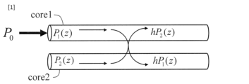
- FIG. 2 is a diagram illustrating a power coupling coefficient.
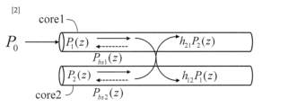
- 1 is a diagram illustrating a power coupling coefficient measuring method according to the present invention
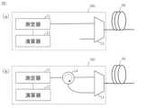
- 1 is a diagram illustrating a power coupling coefficient measurement device according to the present invention
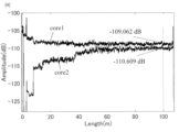
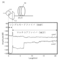
- 1 is a diagram for explaining the intensity of backscattered light from each core of a measured optical fiber 50 acquired by a measuring instrument 11 of the power coupling coefficient measurement device according to the present invention
- 1 is a diagram illustrating a power coupling coefficient of a heterogeneous-core MCF (two cores) measured by a power coupling coefficient measurement device according to the present invention.
- FIG. 13 is a diagram for explaining points to note regarding backscattered light intensity.
- 1 is a diagram for explaining a power coupling coefficient measured by a power coupling coefficient measurement device according to the present invention
- Comparative Example A method for measuring the power coupling coefficient in an MCF with homogeneous cores will be described as a comparative example.
- the MCF will be explained using a two-core fiber.
- test light with optical intensity P0 is incident on the incident core (core1)
- the relationship between the optical intensities of each core at position z in the longitudinal direction from the incident end is described by the power coupling equation in formula (1). Since the cores are of the same type, the power coupling coefficients of each core can be set to the same value h.
- P 1 (z) is the light intensity at position z of the input core (core1)
- P 2 (z) is the optical intensity at position z of the adjacent core (core 2)
- ⁇ 1 is the loss per unit length of the input core (core1)
- ⁇ 2 is the loss per unit length of the adjacent core (core2)
- the backscattered light intensity (P bs1 (z), P bs2 (z)) of each core at position z can be expressed as follows: where ⁇ s (z) is the scattering coefficient at position z, and B(z) is the capture rate at position z. Therefore, the power coupling coefficient h can be obtained from the ratio of the backscattered light intensities.
- the backscattered light intensity (P bs1 (z), P bs2 (z)) of each core at position z can be expressed as follows: where ⁇ s (z) is the scattering coefficient at position z, and B(z) is the capture rate at position z.
- equation (8) the power coupling coefficient of each core of the heterogeneous core coupled MCF can be calculated as follows.
- Example 2 3 is a diagram illustrating an apparatus 301 for measuring the power coupling coefficient of an MCF, which is an optical fiber 50 to be measured.
- the apparatus 301 includes a measuring device 11, a computing device 12, and an optical branching component 13.
- the optical branching component 13 can input light from the measuring device 11 to any core of the MCF and input light from any core of the MCF to the measuring device 11.
- the optical branching component 13 is, for example, a fan-in/fan-out component.
- the MCF of the test optical fiber 50 has an asymmetric power coupling coefficient between the cores.
- the measuring instrument 11 is Injecting test light into an input core, which is one of the cores, at one end of the multi-core optical fiber; and measuring backscattered light intensities (P bs1 (z), P bs2 (z)) of backscattered light output from the input core and an adjacent core adjacent to the input core, at one end of the multi-core optical fiber.
- the measuring instrument 11 is, for example, an OFDR (OFDR).
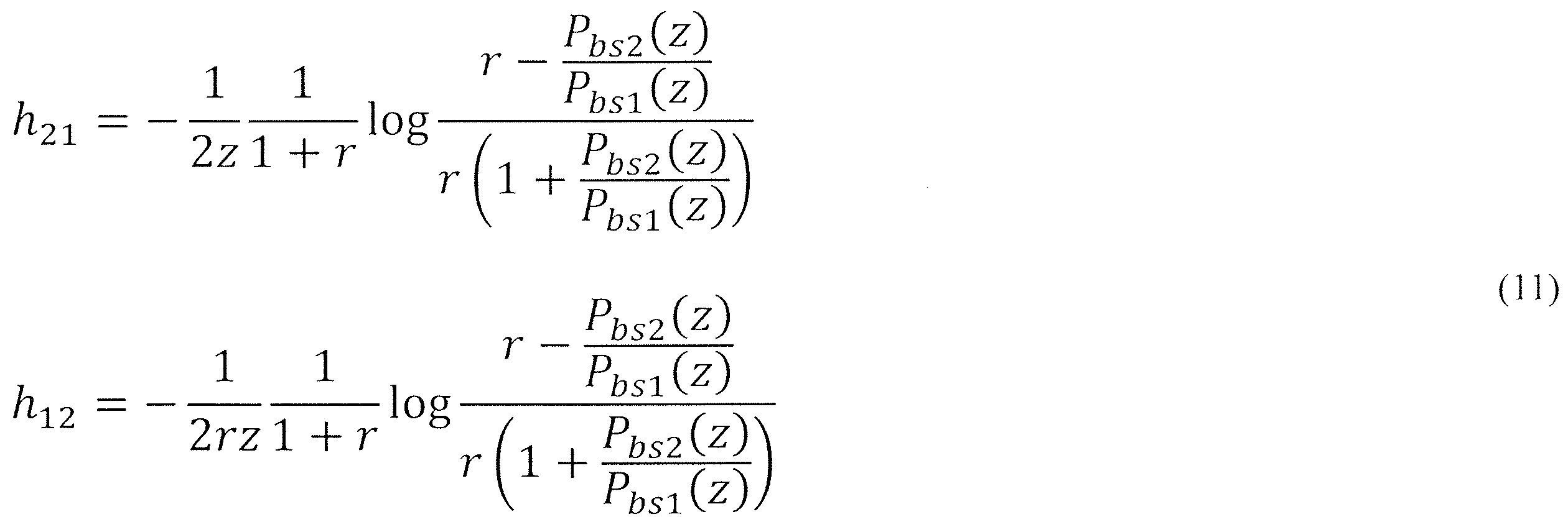
- the calculator 12 is Calculating a ratio r between the backscattered light intensity of the incident core and the backscattered light intensity of the adjacent core from a distance where the backscattered light intensity ratio becomes steady in the longitudinal direction from one end of the multi-core optical fiber; and Substituting the backscattered light intensity of the incident core and the adjacent core at an arbitrary point z in the longitudinal direction from one end of the multi-core optical fiber and the ratio into calculation formula (11) to calculate the power coupling coefficients ( h21 , h12 ) between the cores.
- "far” means a region where the backscattered light intensity ratio is constant. For example, in the case of the optical fiber in FIG. 4, it is a region where z ⁇ 50 m. Note that the "far” region differs depending on the optical fiber, so it does not always mean that 50 m or more is far.
- the device 301 measures the backscattered light intensity P bs1 (z) from the incident core using a circuit as shown in Fig. 3(a). Next, the device 301 measures the backscattered light intensity P bs2 (z) from the adjacent core using a circuit as shown in Fig. 3(b). Note that reference numeral 14 denotes an optical circulator.
- FIG. 4 is a diagram for explaining the backscattered light intensity from each core of the measured optical fiber 50 acquired by the measuring instrument 11.
- the horizontal axis is the position z (m), and the vertical axis is the backscattered light intensity (dB).
- P bs1 (z 0 ) -109.062 dB
- P bs2 (z 0 ) -110.609 dB.
- the ratio r in equation (9) can be calculated as follows:
- Fig. 5 is a diagram for explaining the power coupling coefficients of a heterogeneous-core MCF (2 cores) calculated by equation (11) to which the ratio r in equation (12) is applied.
- the horizontal axis is the position z, and the vertical axis is the power coupling coefficient at each position.
- the white line is h12
- the black line is h21 .
- the device 301 measures the backscattered light intensity from each of the first core and the second core when test light is incident on the first core of the MCF, and calculates the power coupling coefficients h12 and h21 by utilizing the fact that the ratio of the backscattered light intensity Pbs2 of the second core to the backscattered light intensity Pbs1 of the first core is equal to the ratio of the power coupling coefficient h21 from the second core to the first core to the power coupling coefficient h12 from the first core to the second core at a long distance.
- the apparatus 301 can measure the power coupling coefficient between the cores of an MCF in which the characteristics of each core are different, which was previously impossible to measure.
- Equation (5) can be rearranged to obtain equation (A1).
- equation (A1) becomes as follows.
- equation (A2) is:
- equation (A4) can be written as follows:
- Measuring instrument 12 Calculating unit 13: Optical branching component 14: Optical circulator 15: Test optical fiber (MCF) 301: Equipment
Landscapes
- Chemical & Material Sciences (AREA)
- Analytical Chemistry (AREA)
- Physics & Mathematics (AREA)
- General Physics & Mathematics (AREA)
- Testing Of Optical Devices Or Fibers (AREA)
Abstract
本発明は、コア間の非対称性を考慮した電力結合係数測定法及びその装置を提供することを目的とする。 本発明に係る装置は、マルチコア光ファイバの一端において、コアの一つである入射コアに試験光を入射すること、及び前記マルチコア光ファイバの一端において、前記入射コアおよびそれに隣接する隣接コアから出力する後方散乱光の後方散乱光強度を測定すること、を行う測定器11と、前記マルチコア光ファイバの一端から長手方向に後方散乱光強度比が定常的になる遠方からの、前記入射コアの前記後方散乱光強度と前記隣接コアの前記後方散乱光強度との比を計算すること、及び前記マルチコア光ファイバの一端から長手方向にある任意点における前記入射コアと前記隣接コアの前記後方散乱光強度、及び前記比を計算式に代入し、コア相互間の前記電力結合係数を計算することを行う演算器12と、を備える。
Description
本開示は、マルチコア光ファイバの電力結合係数を測定する方法及び装置に関する。
光ファイバ1本あたりの伝送容量を拡大する手段として空間分割多重(SDM)伝送技術の研究開発が行われており、マルチコア光ファイバ(MCF)が注目されている。非結合型および結合型MCFではいずれも結合の強さを表す電力結合係数が重要なパラメータである。SDM伝送の実現に向けて、MCFの特性評価は重要であり電力結合係数を測定する技術が必要である。非特許文献1では、コアの特性が均一な同種コアのMCFの電力結合係数を測定する方法が開示されている。
M. Ohashi, K. Kawazu, A. Nakamura and Y. Miyoshi, "Simple backscattered power technique for measuring crosstalk of multi-core fibers," Proc. 17th Opto-Electron. Commun. Conf., pp. 357-358, 2012.
しかし、MCFの各コアの特性が異なる(異種コアMCF)場合は、コア間の電力結合係数が対称でないため非特許文献1の方法を適用することはできない。つまり、異種コアMCFのコア間の電力結合係数を測定することが困難という課題がある。
本発明は、前記課題を解決するために、コア間の非対称性を考慮した電力結合係数測定法及びその装置を提供することを目的とする。
本発明は、前記課題を解決するために、コア間の非対称性を考慮した電力結合係数測定法及びその装置を提供することを目的とする。
上記目的を達成するために、本発明に係る電力結合係数測定方法は、後方散乱光強度比が一定になる遠方での強度比を用いることで、近似的に電力結合係数を求めることとした。
具体的には、本発明に係る電力結合係数測定方法は、コア間の電力結合係数が非対象であるマルチコア光ファイバの前記電力結合係数を測定する方法であって、
前記マルチコア光ファイバの一端において、前記コアの一つである入射コアに試験光を入射すること、
前記マルチコア光ファイバの一端において、前記入射コアおよび前記入射コアに隣接する隣接コアから出力する後方散乱光の後方散乱光強度を測定すること、
前記マルチコア光ファイバの一端から長手方向に後方散乱光強度比が定常的になる遠方からの、前記入射コアの前記後方散乱光強度と前記隣接コアの前記後方散乱光強度との比を計算すること、及び
前記マルチコア光ファイバの一端から長手方向にある任意点における前記入射コアと前記隣接コアの前記後方散乱光強度、及び前記比を計算式に代入し、コア相互間の前記電力結合係数を計算すること
を特徴とする。
前記マルチコア光ファイバの一端において、前記コアの一つである入射コアに試験光を入射すること、
前記マルチコア光ファイバの一端において、前記入射コアおよび前記入射コアに隣接する隣接コアから出力する後方散乱光の後方散乱光強度を測定すること、
前記マルチコア光ファイバの一端から長手方向に後方散乱光強度比が定常的になる遠方からの、前記入射コアの前記後方散乱光強度と前記隣接コアの前記後方散乱光強度との比を計算すること、及び
前記マルチコア光ファイバの一端から長手方向にある任意点における前記入射コアと前記隣接コアの前記後方散乱光強度、及び前記比を計算式に代入し、コア相互間の前記電力結合係数を計算すること
を特徴とする。
また、本発明に係る電力結合係数測定装置は、コア間の電力結合係数が非対象であるマルチコア光ファイバの前記電力結合係数を測定する装置であって、
前記マルチコア光ファイバの一端において、前記コアの一つである入射コアに試験光を入射すること、及び
前記マルチコア光ファイバの一端において、前記入射コアおよび前記入射コアに隣接する隣接コアから出力する後方散乱光の後方散乱光強度を測定すること、
を行う測定器と、
前記マルチコア光ファイバの一端から長手方向に後方散乱光強度比が定常的になる遠方からの、前記入射コアの前記後方散乱光強度と前記隣接コアの前記後方散乱光強度との比を計算すること、及び
前記マルチコア光ファイバの一端から長手方向にある任意点における前記入射コアと前記隣接コアの前記後方散乱光強度、及び前記比を計算式に代入し、コア相互間の前記電力結合係数を計算すること
を行う演算器と、
を備える。
前記マルチコア光ファイバの一端において、前記コアの一つである入射コアに試験光を入射すること、及び
前記マルチコア光ファイバの一端において、前記入射コアおよび前記入射コアに隣接する隣接コアから出力する後方散乱光の後方散乱光強度を測定すること、
を行う測定器と、
前記マルチコア光ファイバの一端から長手方向に後方散乱光強度比が定常的になる遠方からの、前記入射コアの前記後方散乱光強度と前記隣接コアの前記後方散乱光強度との比を計算すること、及び
前記マルチコア光ファイバの一端から長手方向にある任意点における前記入射コアと前記隣接コアの前記後方散乱光強度、及び前記比を計算式に代入し、コア相互間の前記電力結合係数を計算すること
を行う演算器と、
を備える。
異種コアMCFの場合、注目する2つのコア間の電力結合係数は非対称であり、理論的には後方散乱光強度の比からこれらの電力結合係数を求めることはできない。しかし、本発明の電力結合係数測定方法は、遠方において、入射コアの後方散乱光強度Pbs1に対する隣接コアの後方散乱光強度Pbs2の比が、入射コアから隣接コアへの電力結合係数h12に対する隣接コアから入射コアへの電力結合係数h21の比に等しくなること(次式)を利用することで電力結合係数を近似的に求める。
従って、本発明は、コア間の非対称性を考慮した電力結合係数測定法及びその装置を提供することができる。
なお、前記計算式が数C1である。
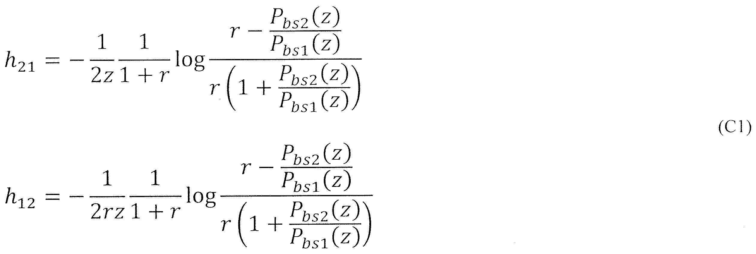
ただし、
h21は前記隣接コアから前記入射コアへの前記電力結合係数、
h12は前記入射コアから前記隣接コアへの前記電力結合係数、
rは前記比、
zは前記一端から前記任意点までの距離(m)、
Pbs1(z)は前記入射コアにて測定される前記任意点からの前記後方散乱光強度(dB)、
Pbs2(z)は前記隣接コアにて測定される前記任意点からの前記後方散乱光強度(dB)
である。
h21は前記隣接コアから前記入射コアへの前記電力結合係数、
h12は前記入射コアから前記隣接コアへの前記電力結合係数、
rは前記比、
zは前記一端から前記任意点までの距離(m)、
Pbs1(z)は前記入射コアにて測定される前記任意点からの前記後方散乱光強度(dB)、
Pbs2(z)は前記隣接コアにて測定される前記任意点からの前記後方散乱光強度(dB)
である。
前記演算器はコンピュータとプログラムによっても実現でき、プログラムを記録媒体に記録することも、ネットワークを通して提供することも可能である。
なお、上記各発明は、可能な限り組み合わせることができる。
本発明は、コア間の非対称性を考慮した電力結合係数測定法及びその装置を提供することができる。
添付の図面を参照して本発明の実施形態を説明する。以下に説明する実施形態は本発明の実施例であり、本発明は、以下の実施形態に制限されるものではない。なお、本明細書及び図面において符号が同じ構成要素は、相互に同一のものを示すものとする。
(比較例)
比較例として同種コアのMCFにおける電力結合係数を測定する方法を説明する。図1は、比較例を説明する図である。
MCFとして2コアファイバで説明する。入射コア(core1)に光強度P0の試験光を入射したとき、入射端から長手方向の位置zにおける各コアの光強度の関係を式(1)の電力結合方程式で記述する。同種コアであるため、各コアの電力結合係数は等しくhとすることができる。
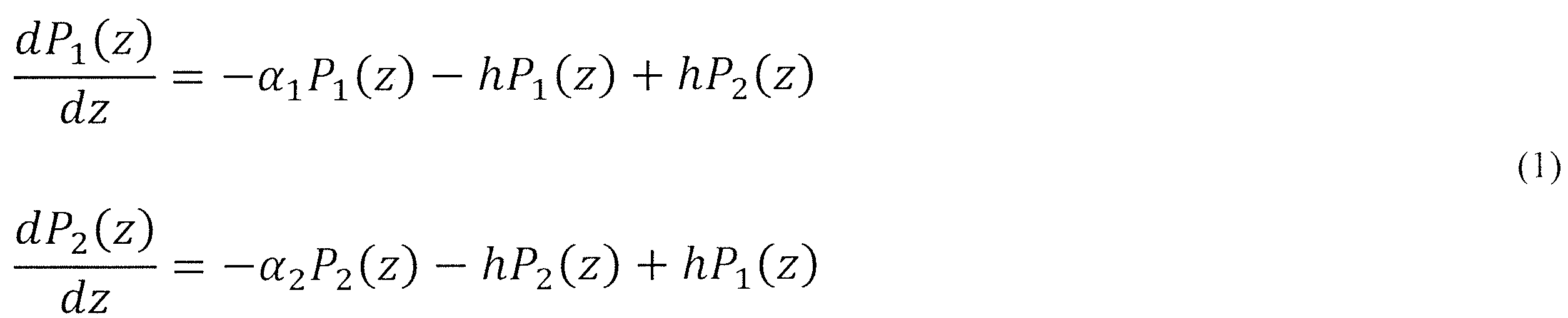
ここで、
P1(z)は入射コア(core1)の位置zにおける光強度、
P2(z)は隣接コア(core2)の位置zにおける光強度、
α1は入射コア(core1)の単位長あたりの損失、
α2は隣接コア(core2)の単位長あたりの損失、
である。
比較例として同種コアのMCFにおける電力結合係数を測定する方法を説明する。図1は、比較例を説明する図である。
MCFとして2コアファイバで説明する。入射コア(core1)に光強度P0の試験光を入射したとき、入射端から長手方向の位置zにおける各コアの光強度の関係を式(1)の電力結合方程式で記述する。同種コアであるため、各コアの電力結合係数は等しくhとすることができる。
P1(z)は入射コア(core1)の位置zにおける光強度、
P2(z)は隣接コア(core2)の位置zにおける光強度、
α1は入射コア(core1)の単位長あたりの損失、
α2は隣接コア(core2)の単位長あたりの損失、
である。
電力方程式の解は式(2)のように表せる。ただし、α1=α2=αとしている。

そして、各コアの位置zにおける後方散乱光強度(Pbs1(z)、Pbs2(z))は以下のように表せる。ただし、αs(z)は位置zにおける散乱係数、B(z)は位置zにおける捕獲率である。

従って、後方散乱光強度の比から電力結合係数hを求めることができる。

(実施例)
次に異種コアのMCFにおける電力結合係数を測定する方法を説明する。図2は、本実施例を説明する図である。
MCFとして2コアファイバで説明する。入射コア(core1)に光強度P0の試験光を入射したとき、入射端から長手方向の位置zにおける各コアの光強度の関係を式(5)の電力結合方程式で記述する。異種コアの場合、各コアの電力結合係数が異なる(h12、h21)。

次に異種コアのMCFにおける電力結合係数を測定する方法を説明する。図2は、本実施例を説明する図である。
MCFとして2コアファイバで説明する。入射コア(core1)に光強度P0の試験光を入射したとき、入射端から長手方向の位置zにおける各コアの光強度の関係を式(5)の電力結合方程式で記述する。異種コアの場合、各コアの電力結合係数が異なる(h12、h21)。
電力方程式の解は式(6)のように表せる。ただし、α1=α2=αとしている。なお、式(6)の導出の委細は付記1に記載する。

そして、各コアの位置zにおける後方散乱光強度(Pbs1(z)、Pbs2(z))は以下のように表せる。ただし、αs(z)は位置zにおける散乱係数、B(z)は位置zにおける捕獲率である。

式(7)より後方散乱光強度の比と電力結合係数の関係は以下のようになる。

ここで、通常であればhについて2変数あるので解けないが、zが十分大きいz=z0場合、各コアの後方散乱光の強度比が一定になることを利用すれば、電力結合係数hを近似的に求めることができる。

つまり、式(9)のように近似することで、式(8)は次式で表現できる。

以上から異種コアの結合型MCFの各コアの電力結合係数は以下のように求められる。
(実施例2)
図3は、被測定光ファイバ50であるMCFの電力結合係数を測定する装置301を説明する図である。装置301は、測定器11、演算器12、及び光分岐部品13を備える。光分岐部品13は、測定器11からの光をMCFの任意のコアに入射し、MCFの任意のコアからの光を測定器11に入力することができる。光分岐部品13は、例えば、ファンイン/ファンアウトである。
図3は、被測定光ファイバ50であるMCFの電力結合係数を測定する装置301を説明する図である。装置301は、測定器11、演算器12、及び光分岐部品13を備える。光分岐部品13は、測定器11からの光をMCFの任意のコアに入射し、MCFの任意のコアからの光を測定器11に入力することができる。光分岐部品13は、例えば、ファンイン/ファンアウトである。
被測定光ファイバ50のMCFは、コア間の電力結合係数が非対象である。
測定器11は、
前記マルチコア光ファイバの一端において、前記コアの一つである入射コアに試験光を入射すること、及び
前記マルチコア光ファイバの一端において、前記入射コアおよび前記入射コアに隣接する隣接コアから出力する後方散乱光の後方散乱光強度(Pbs1(z)、Pbs2(z))を測定すること、
を行う。
測定器11は、例えば、周波数領域反射測定器(OFDR)である。
測定器11は、
前記マルチコア光ファイバの一端において、前記コアの一つである入射コアに試験光を入射すること、及び
前記マルチコア光ファイバの一端において、前記入射コアおよび前記入射コアに隣接する隣接コアから出力する後方散乱光の後方散乱光強度(Pbs1(z)、Pbs2(z))を測定すること、
を行う。
測定器11は、例えば、周波数領域反射測定器(OFDR)である。
演算器12は、
前記マルチコア光ファイバの一端から長手方向に後方散乱光強度比が定常的になる遠方からの、前記入射コアの前記後方散乱光強度と前記隣接コアの前記後方散乱光強度との比rを計算すること、及び
前記マルチコア光ファイバの一端から長手方向にある任意点zにおける前記入射コアと前記隣接コアの前記後方散乱光強度、及び前記比を計算式(11)に代入し、コア相互間の前記電力結合係数(h21、h12)を計算すること
を行う。
なお、「遠方」とは、後方散乱光強度比が一定になる領域を意味する。例えば、図4の光ファイバであればz≧50mの領域である。なお、「遠方」の領域は光ファイバによって異なるので常に50m以上が遠方という意味ではない。
前記マルチコア光ファイバの一端から長手方向に後方散乱光強度比が定常的になる遠方からの、前記入射コアの前記後方散乱光強度と前記隣接コアの前記後方散乱光強度との比rを計算すること、及び
前記マルチコア光ファイバの一端から長手方向にある任意点zにおける前記入射コアと前記隣接コアの前記後方散乱光強度、及び前記比を計算式(11)に代入し、コア相互間の前記電力結合係数(h21、h12)を計算すること
を行う。
なお、「遠方」とは、後方散乱光強度比が一定になる領域を意味する。例えば、図4の光ファイバであればz≧50mの領域である。なお、「遠方」の領域は光ファイバによって異なるので常に50m以上が遠方という意味ではない。
装置301は、図3(a)のような回路で入射コアからの後方散乱光強度Pbs1(z)を測定する。続いて、装置301は、図3(b)のような回路で隣接コアからの後方散乱光強度Pbs2(z)を測定する。なお、符号14は光サーキュレータである。
図4は、測定器11が取得した被測定光ファイバ50の各コアからの後方散乱光強度を説明する図である。横軸は位置z(m)、縦軸は後方散乱光の強度(dB)である。例えば、z=z0=100mにおいては、Pbs1(z0)=-109.062dB、Pbs2(z0)=-110.609dBである。この数値を使えば、式(9)の比rは、次のように計算される。

式(12)の比rを式(11)に適用することで位置zにおける電力結合係数h12とh21を求めることができる。図5は、式(12)の比rを適用した式(11)で算出した異種コアMCF(2コア)の電力結合係数を説明する図である。横軸は位置z、縦軸は各位置における電力結合係数である。白線はh12、黒線はh21である。
(発明の効果)
装置301は、MCFの第1コアに試験光を入射したときの第1コアおよび第2コアそれぞれからの後方散乱光強度を測定し、第1コアの後方散乱光強度Pbs1に対する第2コアの後方散乱光強度Pbs2の比が、遠方では、第1コアから第2コアへの電力結合係数h12に対する第2コアから第1コアへの電力結合係数h21の比に等しくなることを利用して、電力結合係数h12およびh21を計算する。
装置301は、従来測定ができなかった各コアの特性が異なるMCFのコア間の電力結合係数を測定することができる。
装置301は、MCFの第1コアに試験光を入射したときの第1コアおよび第2コアそれぞれからの後方散乱光強度を測定し、第1コアの後方散乱光強度Pbs1に対する第2コアの後方散乱光強度Pbs2の比が、遠方では、第1コアから第2コアへの電力結合係数h12に対する第2コアから第1コアへの電力結合係数h21の比に等しくなることを利用して、電力結合係数h12およびh21を計算する。
装置301は、従来測定ができなかった各コアの特性が異なるMCFのコア間の電力結合係数を測定することができる。
[付記1]
電力結合方程式の一般解の導出を説明する。
式(5)を整理すると式(A1)となる。
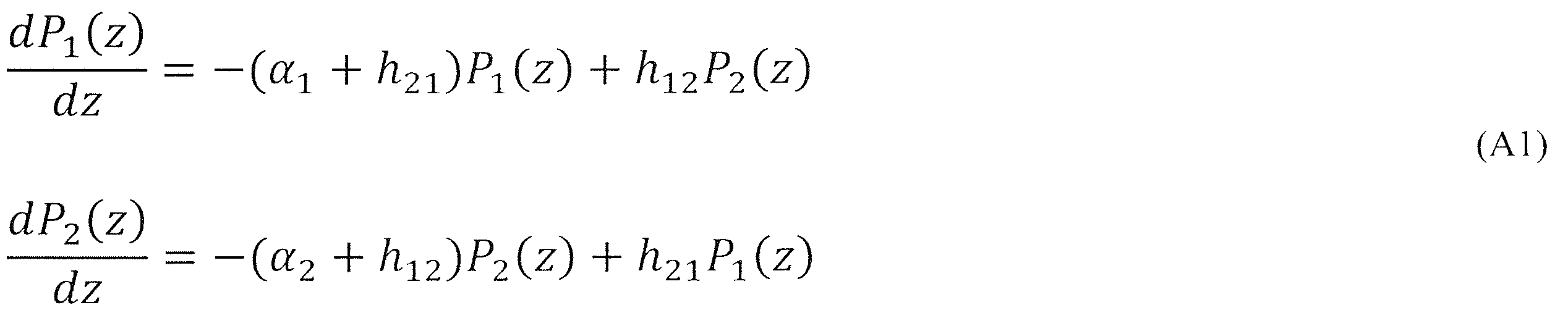
ここで、a=α1+h21、b=h12、c=α2+h12、d=h21とすると、式(A1)は次のようになる。
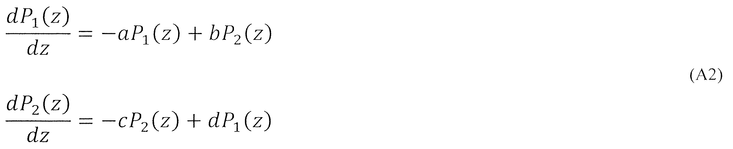
式(A2)の一段目の式をP2(z)について整理し、式(A2)の二段目の式に代入すると次式が得られる。

式(A3)の特性方程式の解は次式となる。
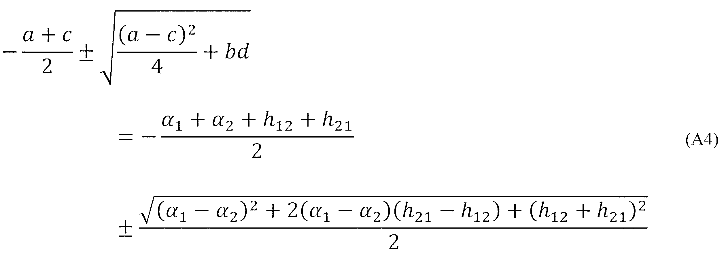
ここで、

とおくと、式(A4)は以下で書ける。

電力結合方程式の一般解の導出を説明する。
式(5)を整理すると式(A1)となる。
初期条件であるP1(0)=P0、P2(0)=0から式(A3)の電力結合方程式の解は以下のようになる。
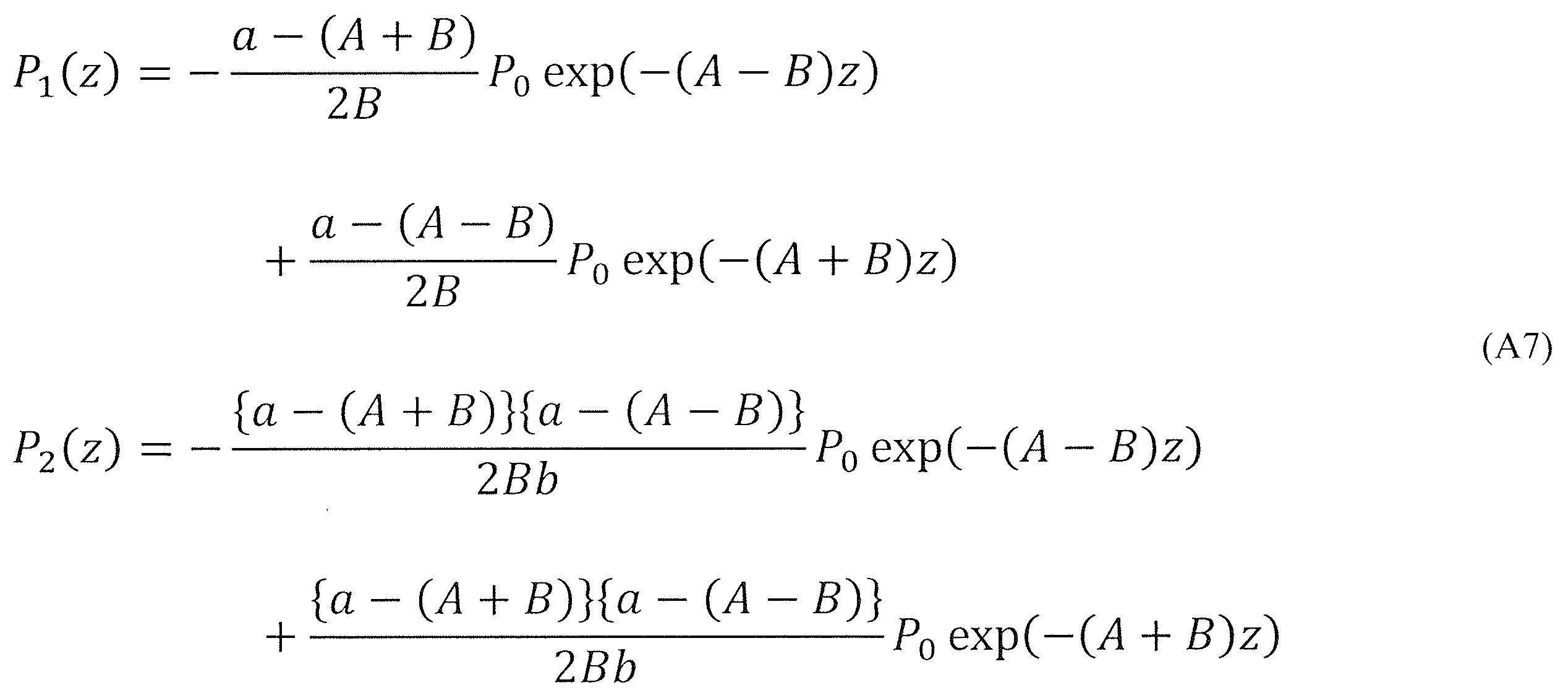
ここで損失係数は各コアで等しい(α1≒α2=α)と仮定すると、
となる。
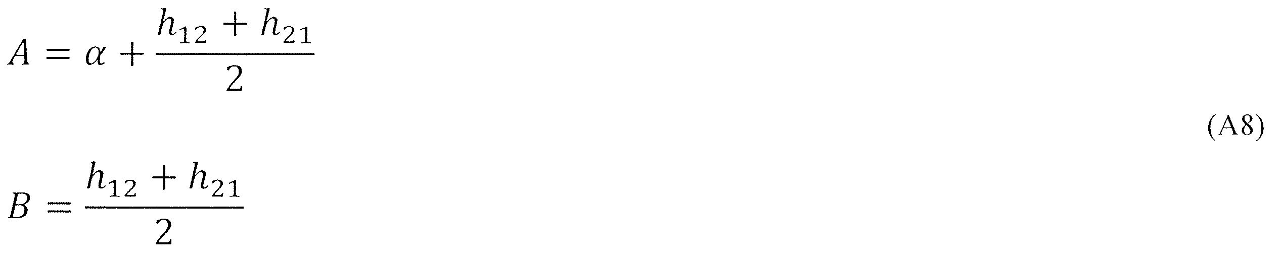
以上から式(A5)の電力結合方程式の解が式(A6)のように求まる。
以上から式(A5)の電力結合方程式の解が式(A6)のように求まる。
[付記2]
図4の後方散乱光強度の測定結果における注意点を説明する。
図5及び図6のように、横軸の位置zは装置301内のファイバデバイス部分も含んでおり、z=0mはMCFの原点ではない。このため、図5においてこの実施例ではz=2m以降の領域がMCFに対する結果を示している。
図4の後方散乱光強度の測定結果における注意点を説明する。
図5及び図6のように、横軸の位置zは装置301内のファイバデバイス部分も含んでおり、z=0mはMCFの原点ではない。このため、図5においてこの実施例ではz=2m以降の領域がMCFに対する結果を示している。
[付記3]
演算器12が計算した電力結合係数についての注意点を説明する。
電力結合係数は、光ファイバの状態によって変化するため、実際には図7の実線のように長手方向に変化する。一方、任意の位置zからの後方散乱光強度(図7の点線)に寄与するのは、位置0からzまでの電力結合係数の積分(図7のハッチング部分)である。装置301は電力結合係数を後方散乱光強度比から求めているため、その値は位置0からzまでの電力結合係数の積分値である。つまり、式(11)で求められるのは、位置0からzまでの平均化された電力結合係数である。
なお、装置301が測定する平均した電力結合係数はzに反比例するのでz=0で発散する。しかし、z=0では結合が起こらないので、z=0での値に物理的な意義がない。
演算器12が計算した電力結合係数についての注意点を説明する。
電力結合係数は、光ファイバの状態によって変化するため、実際には図7の実線のように長手方向に変化する。一方、任意の位置zからの後方散乱光強度(図7の点線)に寄与するのは、位置0からzまでの電力結合係数の積分(図7のハッチング部分)である。装置301は電力結合係数を後方散乱光強度比から求めているため、その値は位置0からzまでの電力結合係数の積分値である。つまり、式(11)で求められるのは、位置0からzまでの平均化された電力結合係数である。
なお、装置301が測定する平均した電力結合係数はzに反比例するのでz=0で発散する。しかし、z=0では結合が起こらないので、z=0での値に物理的な意義がない。
11:測定器
12:演算器
13:光分岐部品
14:光サーキュレータ
15:被測定光ファイバ(MCF)
301:装置
12:演算器
13:光分岐部品
14:光サーキュレータ
15:被測定光ファイバ(MCF)
301:装置
Claims (4)
- コア間の電力結合係数が非対象であるマルチコア光ファイバの前記電力結合係数を測定する方法であって、
前記マルチコア光ファイバの一端において、前記コアの一つである入射コアに試験光を入射すること、
前記マルチコア光ファイバの一端において、前記入射コアおよび前記入射コアに隣接する隣接コアから出力する後方散乱光の後方散乱光強度を測定すること、
前記マルチコア光ファイバの一端から長手方向に後方散乱光強度比が定常的になる遠方からの、前記入射コアの前記後方散乱光強度と前記隣接コアの前記後方散乱光強度との比を計算すること、及び
前記マルチコア光ファイバの一端から長手方向にある任意点における前記入射コアと前記隣接コアの前記後方散乱光強度、及び前記比を計算式に代入し、コア相互間の前記電力結合係数を計算すること
を特徴とする電力結合係数測定方法。 - 前記計算式が数C1であることを特徴とする請求項1に記載の電力結合係数測定方法。
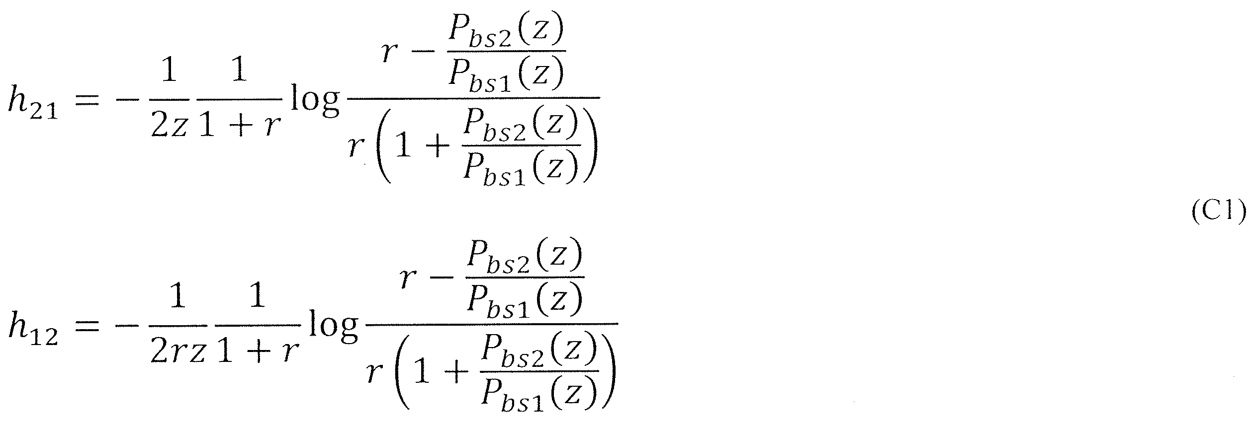
h21は前記隣接コアから前記入射コアへの前記電力結合係数、
h12は前記入射コアから前記隣接コアへの前記電力結合係数、
rは前記比、
zは前記一端から前記任意点までの距離(m)、
Pbs1(z)は前記入射コアにて測定される前記任意点からの前記後方散乱光強度(dB)、
Pbs2(z)は前記隣接コアにて測定される前記任意点からの前記後方散乱光強度(dB)
である。 - コア間の電力結合係数が非対象であるマルチコア光ファイバの前記電力結合係数を測定する装置であって、
前記マルチコア光ファイバの一端において、前記コアの一つである入射コアに試験光を入射すること、及び
前記マルチコア光ファイバの一端において、前記入射コアおよび前記入射コアに隣接する隣接コアから出力する後方散乱光の後方散乱光強度を測定すること、
を行う測定器と、
前記マルチコア光ファイバの一端から長手方向に後方散乱光強度比が定常的になる遠方からの、前記入射コアの前記後方散乱光強度と前記隣接コアの前記後方散乱光強度との比を計算すること、及び
前記マルチコア光ファイバの一端から長手方向にある任意点における前記入射コアと前記隣接コアの前記後方散乱光強度、及び前記比を計算式に代入し、コア相互間の前記電力結合係数を計算すること
を行う演算器と、
を備える電力結合係数測定装置。 - 前記計算式が数C1であることを特徴とする請求項3に記載の電力結合係数測定装置。
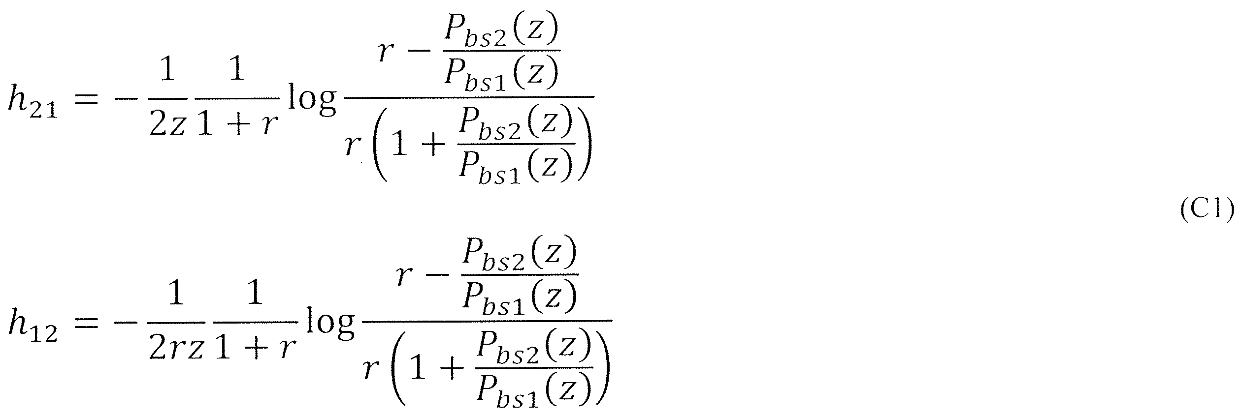
h21は前記隣接コアから前記入射コアへの前記電力結合係数、
h12は前記入射コアから前記隣接コアへの前記電力結合係数、
rは前記比、
zは前記一端から前記任意点までの距離(m)、
Pbs1(z)は前記入射コアにて測定される前記任意点からの前記後方散乱光強度(dB)、
Pbs2(z)は前記隣接コアにて測定される前記任意点からの前記後方散乱光強度(dB)
である。
Priority Applications (2)
| Application Number | Priority Date | Filing Date | Title |
|---|---|---|---|
| JP2025525903A JPWO2024252658A1 (ja) | 2023-06-09 | 2023-06-09 | |
| PCT/JP2023/021500 WO2024252658A1 (ja) | 2023-06-09 | 2023-06-09 | マルチコア光ファイバの電力結合係数を測定する方法及び装置 |
Applications Claiming Priority (1)
| Application Number | Priority Date | Filing Date | Title |
|---|---|---|---|
| PCT/JP2023/021500 WO2024252658A1 (ja) | 2023-06-09 | 2023-06-09 | マルチコア光ファイバの電力結合係数を測定する方法及び装置 |
Publications (1)
| Publication Number | Publication Date |
|---|---|
| WO2024252658A1 true WO2024252658A1 (ja) | 2024-12-12 |
Family
ID=93795573
Family Applications (1)
| Application Number | Title | Priority Date | Filing Date |
|---|---|---|---|
| PCT/JP2023/021500 Ceased WO2024252658A1 (ja) | 2023-06-09 | 2023-06-09 | マルチコア光ファイバの電力結合係数を測定する方法及び装置 |
Country Status (2)
| Country | Link |
|---|---|
| JP (1) | JPWO2024252658A1 (ja) |
| WO (1) | WO2024252658A1 (ja) |
Cited By (1)
| Publication number | Priority date | Publication date | Assignee | Title |
|---|---|---|---|---|
| US12540878B2 (en) * | 2021-09-16 | 2026-02-03 | Ntt, Inc. | Connection loss difference measurement method, equipment and program |
Citations (4)
| Publication number | Priority date | Publication date | Assignee | Title |
|---|---|---|---|---|
| JP2012202827A (ja) * | 2011-03-25 | 2012-10-22 | Tohoku Univ | マルチコア光ファイバ用モード結合測定方法および測定装置 |
| WO2013027776A1 (ja) * | 2011-08-25 | 2013-02-28 | 国立大学法人横浜国立大学 | マルチコアファイバおよびマルチコアファイバのコアの配置方法 |
| JP2021012226A (ja) * | 2019-07-03 | 2021-02-04 | 住友電気工業株式会社 | マルチコア光ファイバ |
| JP2022111486A (ja) * | 2021-01-20 | 2022-08-01 | 日本電信電話株式会社 | 光学特性測定装置及び方法 |
-
2023
- 2023-06-09 JP JP2025525903A patent/JPWO2024252658A1/ja active Pending
- 2023-06-09 WO PCT/JP2023/021500 patent/WO2024252658A1/ja not_active Ceased
Patent Citations (4)
| Publication number | Priority date | Publication date | Assignee | Title |
|---|---|---|---|---|
| JP2012202827A (ja) * | 2011-03-25 | 2012-10-22 | Tohoku Univ | マルチコア光ファイバ用モード結合測定方法および測定装置 |
| WO2013027776A1 (ja) * | 2011-08-25 | 2013-02-28 | 国立大学法人横浜国立大学 | マルチコアファイバおよびマルチコアファイバのコアの配置方法 |
| JP2021012226A (ja) * | 2019-07-03 | 2021-02-04 | 住友電気工業株式会社 | マルチコア光ファイバ |
| JP2022111486A (ja) * | 2021-01-20 | 2022-08-01 | 日本電信電話株式会社 | 光学特性測定装置及び方法 |
Non-Patent Citations (1)
| Title |
|---|
| NAKAZAWA M. ET AL.: "Nondestructive measurement of mode couplings along a multi-core fiber using a synchronous multi-channel OTDR", OPTICS EXPRESS, vol. 20, no. 11, 18 May 2012 (2012-05-18), pages 12530 - 12540, XP055909442 * |
Cited By (1)
| Publication number | Priority date | Publication date | Assignee | Title |
|---|---|---|---|---|
| US12540878B2 (en) * | 2021-09-16 | 2026-02-03 | Ntt, Inc. | Connection loss difference measurement method, equipment and program |
Also Published As
| Publication number | Publication date |
|---|---|
| JPWO2024252658A1 (ja) | 2024-12-12 |
Similar Documents
| Publication | Publication Date | Title |
|---|---|---|
| JP5685763B2 (ja) | マルチコア光ファイバ用モード結合測定方法および測定装置 | |
| JP7375942B2 (ja) | 電力結合係数測定方法及び電力結合係数測定装置 | |
| Kagami et al. | Encircled angular flux representation of the modal power distribution and its behavior in a step index multimode fiber | |
| EP3623789B1 (en) | Nonlinearity measuring method and nonlinearity measuring device | |
| JP7070695B2 (ja) | 光ファイバ試験方法及び光ファイバ試験装置 | |
| US11828676B2 (en) | Optical pulse reflectometry and optical pulse reflectometer | |
| KR20050084946A (ko) | 광시영역 반사율 측정기를 이용한 광섬유 편광분산모드의평가 방법 | |
| WO2024252658A1 (ja) | マルチコア光ファイバの電力結合係数を測定する方法及び装置 | |
| Rademacher et al. | Time-dependent crosstalk from multiple cores in a homogeneous multi-core fiber | |
| CN110855373A (zh) | 一种光纤通信系统防窃听装置和方法 | |
| CN121488146A (zh) | 串扰测量装置和串扰测量方法 | |
| JP7468638B2 (ja) | ブリルアン光センシング装置および光センシング方法 | |
| CN101325454B (zh) | 一种在光纤偏振模色散测试中降低不确定度的方法 | |
| US10337956B2 (en) | Method of qualifying wide-band multimode fiber from single wavelength characterization using EMB extrapolation, corresponding system and computer program | |
| JP7006537B2 (ja) | ラマン利得効率分布試験方法およびラマン利得効率分布試験装置 | |
| JP7380892B2 (ja) | 数モードファイバ試験方法及び数モードファイバ試験装置 | |
| Lorenz et al. | Asymmetric optical bus coupler for interruption-free short-range connections on board and module level | |
| CN119213287A (zh) | 串扰测定方法和串扰测定装置 | |
| JP4938431B2 (ja) | 光ファイバ温度・歪測定方法 | |
| CN105203135B (zh) | 一种基于直波导‑反馈波导‑环‑直波导的高灵敏度谐振系统 | |
| JP2017203625A (ja) | 光パルス試験方法及び光パルス試験装置 | |
| WO2024038487A1 (ja) | 双方向のクロストークを評価する装置及び方法 | |
| JP2022111484A (ja) | モードフィールド径測定装置および測定方法 | |
| Abdelmoniem et al. | Experimental characterization of Plastic Optical Fibers for Under-and Over-Filled Injections | |
| Luis et al. | Cumulative Dynamic Inter-Core Skew Measurements in Spooled Uncoupled Core Multicore Fibers |
Legal Events
| Date | Code | Title | Description |
|---|---|---|---|
| 121 | Ep: the epo has been informed by wipo that ep was designated in this application |
Ref document number: 23940756 Country of ref document: EP Kind code of ref document: A1 |
|
| ENP | Entry into the national phase |
Ref document number: 2025525903 Country of ref document: JP Kind code of ref document: A |
|
| NENP | Non-entry into the national phase |
Ref country code: DE |