WO2024252677A1 - 車両検知センサ及び車両検知センサ用プログラム - Google Patents
車両検知センサ及び車両検知センサ用プログラム Download PDFInfo
- Publication number
- WO2024252677A1 WO2024252677A1 PCT/JP2023/021582 JP2023021582W WO2024252677A1 WO 2024252677 A1 WO2024252677 A1 WO 2024252677A1 JP 2023021582 W JP2023021582 W JP 2023021582W WO 2024252677 A1 WO2024252677 A1 WO 2024252677A1
- Authority
- WO
- WIPO (PCT)
- Prior art keywords
- detection sensor
- information
- area
- vehicle detection
- wave
- Prior art date
- Legal status (The legal status is an assumption and is not a legal conclusion. Google has not performed a legal analysis and makes no representation as to the accuracy of the status listed.)
- Ceased
Links
Images


Classifications
-
- G—PHYSICS
- G08—SIGNALLING
- G08G—TRAFFIC CONTROL SYSTEMS
- G08G1/00—Traffic control systems for road vehicles
- G08G1/14—Traffic control systems for road vehicles indicating individual free spaces in parking areas
- G08G1/149—Traffic control systems for road vehicles indicating individual free spaces in parking areas coupled to means for restricting the access to the parking space, e.g. authorization, access barriers, indicative lights
-
- G—PHYSICS
- G01—MEASURING; TESTING
- G01S—RADIO DIRECTION-FINDING; RADIO NAVIGATION; DETERMINING DISTANCE OR VELOCITY BY USE OF RADIO WAVES; LOCATING OR PRESENCE-DETECTING BY USE OF THE REFLECTION OR RERADIATION OF RADIO WAVES; ANALOGOUS ARRANGEMENTS USING OTHER WAVES
- G01S13/00—Systems using the reflection or reradiation of radio waves, e.g. radar systems; Analogous systems using reflection or reradiation of waves whose nature or wavelength is irrelevant or unspecified
- G01S13/02—Systems using reflection of radio waves, e.g. primary radar systems; Analogous systems
- G01S13/04—Systems determining presence of a target
-
- G—PHYSICS
- G01—MEASURING; TESTING
- G01S—RADIO DIRECTION-FINDING; RADIO NAVIGATION; DETERMINING DISTANCE OR VELOCITY BY USE OF RADIO WAVES; LOCATING OR PRESENCE-DETECTING BY USE OF THE REFLECTION OR RERADIATION OF RADIO WAVES; ANALOGOUS ARRANGEMENTS USING OTHER WAVES
- G01S13/00—Systems using the reflection or reradiation of radio waves, e.g. radar systems; Analogous systems using reflection or reradiation of waves whose nature or wavelength is irrelevant or unspecified
- G01S13/02—Systems using reflection of radio waves, e.g. primary radar systems; Analogous systems
- G01S13/06—Systems determining position data of a target
- G01S13/08—Systems for measuring distance only
- G01S13/32—Systems for measuring distance only using transmission of continuous waves, whether amplitude-, frequency-, or phase-modulated, or unmodulated
- G01S13/34—Systems for measuring distance only using transmission of continuous waves, whether amplitude-, frequency-, or phase-modulated, or unmodulated using transmission of continuous, frequency-modulated waves while heterodyning the received signal, or a signal derived therefrom, with a locally-generated signal related to the contemporaneously transmitted signal
- G01S13/343—Systems for measuring distance only using transmission of continuous waves, whether amplitude-, frequency-, or phase-modulated, or unmodulated using transmission of continuous, frequency-modulated waves while heterodyning the received signal, or a signal derived therefrom, with a locally-generated signal related to the contemporaneously transmitted signal using sawtooth modulation
-
- G—PHYSICS
- G01—MEASURING; TESTING
- G01S—RADIO DIRECTION-FINDING; RADIO NAVIGATION; DETERMINING DISTANCE OR VELOCITY BY USE OF RADIO WAVES; LOCATING OR PRESENCE-DETECTING BY USE OF THE REFLECTION OR RERADIATION OF RADIO WAVES; ANALOGOUS ARRANGEMENTS USING OTHER WAVES
- G01S13/00—Systems using the reflection or reradiation of radio waves, e.g. radar systems; Analogous systems using reflection or reradiation of waves whose nature or wavelength is irrelevant or unspecified
- G01S13/88—Radar or analogous systems specially adapted for specific applications
- G01S13/91—Radar or analogous systems specially adapted for specific applications for traffic control
-
- G—PHYSICS
- G01—MEASURING; TESTING
- G01S—RADIO DIRECTION-FINDING; RADIO NAVIGATION; DETERMINING DISTANCE OR VELOCITY BY USE OF RADIO WAVES; LOCATING OR PRESENCE-DETECTING BY USE OF THE REFLECTION OR RERADIATION OF RADIO WAVES; ANALOGOUS ARRANGEMENTS USING OTHER WAVES
- G01S7/00—Details of systems according to groups G01S13/00, G01S15/00, G01S17/00
- G01S7/02—Details of systems according to groups G01S13/00, G01S15/00, G01S17/00 of systems according to group G01S13/00
- G01S7/027—Constructional details of housings, e.g. form, type, material or ruggedness
-
- G—PHYSICS
- G01—MEASURING; TESTING
- G01S—RADIO DIRECTION-FINDING; RADIO NAVIGATION; DETERMINING DISTANCE OR VELOCITY BY USE OF RADIO WAVES; LOCATING OR PRESENCE-DETECTING BY USE OF THE REFLECTION OR RERADIATION OF RADIO WAVES; ANALOGOUS ARRANGEMENTS USING OTHER WAVES
- G01S7/00—Details of systems according to groups G01S13/00, G01S15/00, G01S17/00
- G01S7/02—Details of systems according to groups G01S13/00, G01S15/00, G01S17/00 of systems according to group G01S13/00
- G01S7/41—Details of systems according to groups G01S13/00, G01S15/00, G01S17/00 of systems according to group G01S13/00 using analysis of echo signal for target characterisation; Target signature; Target cross-section
- G01S7/415—Identification of targets based on measurements of movement associated with the target
-
- G—PHYSICS
- G08—SIGNALLING
- G08G—TRAFFIC CONTROL SYSTEMS
- G08G1/00—Traffic control systems for road vehicles
- G08G1/01—Detecting movement of traffic to be counted or controlled
- G08G1/0104—Measuring and analyzing of parameters relative to traffic conditions
- G08G1/0108—Measuring and analyzing of parameters relative to traffic conditions based on the source of data
- G08G1/0116—Measuring and analyzing of parameters relative to traffic conditions based on the source of data from roadside infrastructure, e.g. beacons
-
- G—PHYSICS
- G08—SIGNALLING
- G08G—TRAFFIC CONTROL SYSTEMS
- G08G1/00—Traffic control systems for road vehicles
- G08G1/01—Detecting movement of traffic to be counted or controlled
- G08G1/052—Detecting movement of traffic to be counted or controlled with provision for determining speed or overspeed
-
- G—PHYSICS
- G01—MEASURING; TESTING
- G01S—RADIO DIRECTION-FINDING; RADIO NAVIGATION; DETERMINING DISTANCE OR VELOCITY BY USE OF RADIO WAVES; LOCATING OR PRESENCE-DETECTING BY USE OF THE REFLECTION OR RERADIATION OF RADIO WAVES; ANALOGOUS ARRANGEMENTS USING OTHER WAVES
- G01S13/00—Systems using the reflection or reradiation of radio waves, e.g. radar systems; Analogous systems using reflection or reradiation of waves whose nature or wavelength is irrelevant or unspecified
- G01S13/02—Systems using reflection of radio waves, e.g. primary radar systems; Analogous systems
- G01S13/06—Systems determining position data of a target
- G01S13/46—Indirect determination of position data
- G01S13/48—Indirect determination of position data using multiple beams at emission or reception
-
- G—PHYSICS
- G07—CHECKING-DEVICES
- G07B—TICKET-ISSUING APPARATUS; FARE-REGISTERING APPARATUS; FRANKING APPARATUS
- G07B15/00—Arrangements or apparatus for collecting fares, tolls or entrance fees at one or more control points
- G07B15/06—Arrangements for road pricing or congestion charging of vehicles or vehicle users, e.g. automatic toll systems
Definitions
- the present invention relates to a vehicle detection sensor that is installed on a site where vehicles enter and exit, and a program for the vehicle detection sensor.
- loop coil sensors have been used to detect vehicles in parking areas in car parks and parking areas next to ticket machines, but this has various issues, such as the need for construction to bury the loop coil underground and the need for extensive work to dig up the ground during maintenance.
- Such vehicle detection sensors use FMCW radar, which has excellent environmental resistance against rain and other elements, and among these, inexpensive SISO (Single Input Single Output) type sensors are used. Using this, vehicles can be detected by emitting a transmission wave whose frequency changes over time and receiving the reflected wave that is reflected by an object, which not only significantly shortens the construction period but also reduces the effort and costs involved in maintenance.
- SISO Single Input Single Output
- the present invention was made to solve all of the above problems at once, and its main objective is to provide an inexpensive vehicle detection sensor with high detection accuracy that can distinguish between vehicles and pedestrians and detect vehicles entering and exiting a specified area.
- the vehicle detection sensor of the present invention is a vehicle detection sensor that is installed at a predetermined location on a site where vehicles enter and exit, emits a transmission wave whose frequency changes over time, and receives a reflected wave that is reflected by an object and returns.
- the vehicle detection sensor includes a speed information acquisition unit that acquires speed information related to the speed of an object approaching or moving away from a predetermined area based on the reflected wave, an object discrimination unit that determines whether or not the object is a vehicle based on the speed information, and a presence/absence determination unit that determines whether or not an object is in the predetermined area based on at least one of reflection intensity information indicating the intensity of the reflected wave or distance information indicating the distance to the object obtained based on the reflected wave, and is characterized in that the speed information and at least one of the reflection intensity information and the distance information are information obtained by a SISO method.
- a vehicle detection sensor configured in this manner can determine whether an object is a vehicle based on the speed information obtained by the SISO method, and can determine whether an object is in a specified area based on at least one of the reflection intensity information and distance information obtained by the SISO method. This means that there is no need to use expensive MIMO type sensors, and a vehicle detection sensor with high detection accuracy can be provided at low cost.
- the system includes a reflection intensity information acquisition unit that acquires the reflection intensity information and a distance information acquisition unit that acquires the distance information, and the presence/absence determination unit determines whether or not an object is present in the specified area based on the reflection intensity information and the distance information.
- the presence or absence of an object is determined based on both reflection intensity information and distance information, which provides more information to make a judgment than if it were based on either reflection intensity information or distance information alone, making it possible to more reliably determine the presence or absence of an object in a specified area.
- the radio wave is configured to emit a transmission wave toward the specified area, and also to emit a transmission wave toward a forward area or a rear area away from the specified area in the direction in which the vehicle enters or exits.
- a transmission wave toward a specified area a stable reflection intensity can be obtained from vehicles present in the specified area, making it easier to determine whether or not an object is present, and by emitting a transmission wave toward the forward or rearward area, speed information can be obtained to determine whether or not an object is a vehicle.
- the transmission wave directed toward the specified area and the transmission wave directed toward the front area or the rear area are emitted from a common transmitter, and that the reflected waves that are reflected back from the transmission waves by an object are each received by a common receiver. This would result in an embodiment using a single pair of transmitter and receiver, further reducing the cost of the sensor.
- a transmission/reception pattern indicating a transmission/reception antenna gain obtained by combining a transmission antenna gain of the transmitter corresponding to the radiation angle of the transmitted wave and a reception antenna gain of the receiver corresponding to the reception angle of the reflected wave has a first peak that appears in the front direction and a quasi-peak that appears at an angle different from the front direction and is smaller than the first peak.
- a difference in intensity is generated between the first peak and the quasi-peak, it becomes possible to determine whether the received reflected wave has returned from a specified area, or from the front or rear area, which makes it possible to accurately determine whether a vehicle is present in a specified area, even in an environment where the road width is wide.
- the transmission and reception pattern has the quasi-peaks on both the high-angle side and the low-angle side of the first peak. In this way, it is possible to determine whether an object approaching a specified area or an object moving away from the specified area is a vehicle or not. As a result, for example, by using the detection of the speed of a moving object moving away as one of the criteria for determining that a vehicle has left a specified area, it is possible to improve the accuracy of the exit determination. Furthermore, with the above-mentioned configuration, the vehicle detection sensor according to the present invention can be used for both the left lane and the right lane.
- This makes it possible to increase the radiation power of the transmission wave directed toward the forward or rear area, and makes it possible to easily realize a configuration for emitting a transmission wave to a specified area while also emitting a transmission wave to the forward or rear area by using a dielectric lens.
- the first peak is usually made steep, but making a quasi-peak appear in addition to the first peak is an idea unique to the present invention.
- the vehicle detection sensor program of the present invention is a program used in a vehicle detection sensor that is installed at a designated location on a site where vehicles enter and exit, emits a transmission wave whose frequency changes over time, and receives a reflected wave that is the transmission wave reflected by an object and returns, and causes a computer to function as a speed information acquisition unit that acquires speed information regarding the speed of an object approaching or moving away from a designated area based on the reflected wave, an object discrimination unit that determines whether the object is a vehicle based on the speed information, and a presence/absence determination unit that determines whether an object is in the designated area based on at least one of reflection intensity information indicating the intensity of the reflected wave or distance information indicating the distance to the object obtained based on the reflected wave, and is characterized in that the speed information and at least one of the reflection intensity information and the distance information are information obtained by a SISO method.
- the vehicle detection sensor program configured in this manner can achieve the same effects as the vehicle detection sensor described above.
- the present invention configured in this way, can provide an inexpensive vehicle detection sensor with high detection accuracy that can distinguish between vehicles and pedestrians and detect vehicles entering and exiting a specified area.
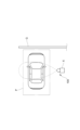
- FIG. 1 is a schematic diagram showing an example of installation of a vehicle detection system according to an embodiment of the present invention
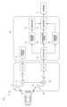
- FIG. 2 is a schematic diagram showing the configuration of a vehicle detection sensor according to the embodiment
- FIG. 2 is a diagram for explaining the principle of the FMCW radar of the embodiment.
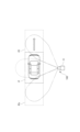
- 2 is a schematic diagram showing a transmission wave emitted from the vehicle detection sensor of the embodiment
- FIG. 4 is a transmission/reception pattern showing the transmission/reception antenna gains of the embodiment
- FIG. 2 is a schematic diagram showing the configuration of a vehicle detection sensor according to the embodiment
- FIG. 2 is a schematic diagram showing the configuration of a dielectric lens of the embodiment.
- 5A to 5C are diagrams for explaining the operation of the object discriminator of the embodiment.
- FIG. 4 is a flowchart illustrating the operation of the vehicle detection sensor according to the embodiment.
- FIG. 4 is a flowchart illustrating the operation of the vehicle detection sensor according to the embodiment.
- a vehicle detection sensor according to one embodiment of the present invention will be described with reference to the drawings. However, the present invention is not limited to the following description.
- the vehicle detection sensor 100 of this embodiment is fixedly installed at a predetermined location on a site where vehicles enter and exit, and detects vehicles entering and exiting a predetermined area P, such as a parking area next to a ticket machine as shown in FIG. 1, or a parking area in a parking lot (not shown).
- a predetermined area P such as a parking area next to a ticket machine as shown in FIG. 1, or a parking area in a parking lot (not shown).
- this predetermined area P is not only an area where a vehicle is stopped or should be stopped, but may also be an area where a vehicle should slow down to a predetermined speed, such as an ETC-compatible toll booth on a highway.
- this vehicle detection sensor 100 is provided in correspondence with a stopping area P provided in front of a movable gate G, such as a gate bar or chain gate that rises and falls, or a sliding gate that opens and closes from side to side, and is attached to a fixed member X, such as a pole, provided at a predetermined location near the stopping area P.
- a movable gate G such as a gate bar or chain gate that rises and falls, or a sliding gate that opens and closes from side to side
- a fixed member X such as a pole
- the vehicle detection sensor 100 of this embodiment is configured using an FMCW radar, and emits a transmission wave whose frequency changes over time, and receives the reflected wave that is reflected back by an object.
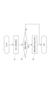
- the vehicle detection sensor 100 includes a transmitter 10 that emits a transmission wave whose frequency changes over time, a receiver 20 that receives a reflected wave that is the transmission wave reflected by an object, a mixer 30 that mixes the transmission wave and the reflected wave to generate a beat signal, and a controller 40 that controls the operation of the sensor.
- the transmitter 10 has at least a transmission antenna 11 and a voltage-controlled oscillator 12, and the receiver 20 has at least a receiving antenna 21.
- the vehicle detection sensor 100 of this embodiment is configured to detect the presence or absence of a vehicle in a specified area P, and outputs this presence or absence information to a control device C that controls, for example, the operation of the movable gate G described above.
- the vehicle detection sensor 100 is configured to emit a transmission wave toward a predetermined area P, and also to emit a transmission wave toward a forward area Pf and a rear area Pb that are located forward and rearward from the predetermined area P along the direction in which the vehicle enters and exits.
- the vehicle detection sensor 100 does not necessarily need to emit a transmission wave to both the forward area Pf and the rearward area Pb, and may be configured to emit a transmission wave to at least one of the forward area Pf or the rearward area Pb while emitting a transmission wave to a specified area P in front.
- This vehicle detection sensor 100 is configured so that a transmission wave directed toward a specified area P and a transmission wave directed toward a forward area Pf or a rearward area Pb are emitted from a common transmitter, and the reflected waves that are returned after being reflected by an object from these transmission waves are received by a common receiver 20.
- the vehicle detection sensor 100 here is characterized by a transmission and reception pattern that indicates the transmission and reception antenna gains corresponding to the transmitter and receiver 20.
- a transmission/reception pattern indicating a transmission/reception antenna gain obtained by combining the transmission antenna gain of the transmitter corresponding to the radiation angle of the transmitted wave and the reception antenna gain of the receiver 20 corresponding to the reception angle of the reflected wave has a first peak that appears in the front direction and a quasi-peak that appears at an angle different from the front direction and is smaller than the first peak.
- the thick solid line indicates the transmission and reception pattern of the vehicle detection sensor 100 in this embodiment, and the thin solid line indicates a comparative example, which will be described later.
- the transmission pattern indicating the transmitting antenna gain and the reception pattern indicating the receiving antenna gain each have a peak corresponding to the first peak and a peak corresponding to the quasi-peak, but even if, for example, one of the transmission pattern and the reception pattern does not have a peak corresponding to the quasi-peak, it is sufficient that the transmission and reception pattern obtained as a result of combining them has the first peak and the quasi-peak.
- the transmission and reception pattern of this embodiment has quasi-peaks on both the high-angle and low-angle sides of the first peak, which allows a common receiver 20 to receive reflected waves returning from the front direction and reflected waves returning from a side that is offset by a specified angle from the front direction.
- a peak is a point that includes an inflection point where the slope of the radiated power with respect to the radiation angle switches from increasing to decreasing or from decreasing to increasing.
- the first peak appears in the front direction of the sensor (0 degree direction), and quasi-peaks appear in the directions of 30 degrees to 70 degrees and -30 degrees to -70 degrees.
- the vehicle detection sensor of this embodiment has sensitivity in the directions of 30 degrees to 70 degrees and -30 degrees to -70 degrees.
- the above-mentioned transmission and reception pattern can create a difference between the reflection intensity of the reflected wave from the specified area P and the reflection intensity of the reflected wave from the forward area Pf or the rearward area Pb, where the latter reflection intensity is weaker than the former reflection intensity.
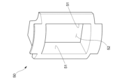
- the vehicle detection sensor 100 of this embodiment is equipped with a dielectric lens 50 that refracts a portion of the transmission wave emitted from the transmitter and directs it to the forward area Pf or the rearward area Pb, as shown in Figures 6 and 7.
- a dielectric lens 50 that refracts a portion of the transmission wave emitted from the transmitter and directs it to the forward area Pf or the rearward area Pb, as shown in Figures 6 and 7.
- the transmission and reception pattern of a configuration that does not have this dielectric lens 50 is a comparative example shown by a thin solid line in Figure 5.
- This dielectric lens 50 has multiple lens surfaces 51 arranged to surround the transmitting antenna 11 and the receiving antenna 21, and a radio wave passage 52, which is a space formed inside these lens surfaces 51.
- the lens surfaces 51 refract the radio waves transmitted and received between the transmitting antenna 11 and the receiving antenna 21, and are arranged to stand up from the substrate B on which the transmitting antenna 11 and the receiving antenna 21 are arranged.
- the radio wave passage 52 opens to face the transmitting antenna 11 and the receiving antenna 21, and here has a rectangular shape when viewed from the front.
- the shape of the radio wave passage 52 is not limited to this, and may be redefined to be, for example, an elliptical, circular, or polygonal shape.
- a pair of lens surfaces 51 are arranged at positions sandwiching the transmitting antenna 11 and the receiving antenna 21 in the width direction (horizontal direction), and these lens surfaces 51 are inclined so as to gradually approach the transmitting antenna 11 and the receiving antenna 21 toward the substrate B.
- the radio wave passage 52 is formed so that its width gradually narrows toward the transmitting antenna 11 and the receiving antenna 21.
- the transmitted wave is emitted from the transmitting antenna 11 in the front direction without being refracted, and is emitted to the side from the transmitting antenna 11 while being refracted through the lens surface 51.
- the reflected wave is guided to the receiving antenna 21 from the front direction without being refracted, and is guided to the receiving antenna 21 from the side while being refracted through the lens surface 51.
- the controller 40 physically comprises a CPU, memory, etc., and functionally, the CPU and its peripheral devices operate in accordance with the vehicle detection program stored in the memory, thereby performing the functions of a control signal generating unit 41, a signal receiving unit 42, a speed information acquiring unit 43, an object discriminating unit 44, a reflection intensity information acquiring unit 45, a distance information acquiring unit 46, and a presence/absence determining unit 47, as shown in Figure 2.
- the operation of the controller 40 will be described below together with an explanation of each component.
- the control signal generating unit 41 outputs a control signal to the voltage controlled oscillator 12 via a D/A converter, an amplifier, etc., and this causes a transmission wave whose frequency changes over time to be transmitted from the transmitting antenna 11.
- This transmission wave is a pulse wave also known as a chirp.
- the transmitter 10 of this embodiment periodically emits a transmission wave called a chirp.
- the signal receiving unit 42 receives the beat signal received by the receiver 20, and more specifically, receives an analog value that indicates a sine wave signal with an amplitude proportional to the strength of the reflected wave and a frequency proportional to the distance of the object.
- the speed information acquisition unit 43 acquires speed information regarding the speed of an object based on the reflected waves from the object, and more specifically, acquires speed information regarding the speed of an object approaching or moving away from the above-mentioned specified area P.
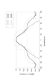
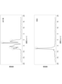
- the speed information acquisition unit 43 of this embodiment processes the beat signal received by the signal reception unit 42 described above, and acquires, as speed information, a speed distribution that can be represented on a graph with one axis representing speed and the other axis representing amplitude, as shown in FIG. 8.
- One example of signal processing for obtaining velocity information is to calculate the distance and phase of an object by performing frequency analysis such as a Fourier transform on the beat signal, and obtain velocity information based on the changes in the distance and phase over time.
- frequency analysis such as a Fourier transform
- the shape of the speed distribution described above differs depending on whether the object reflecting the transmitted wave is a pedestrian or a vehicle, in other words, whether the object from which the reflected wave originates is a pedestrian or a vehicle.
- the velocity components resulting from the movement of the hands and feet will appear in the distribution, resulting in multiple peaks, whereas if the object is a vehicle, a sharp peak will appear at a certain speed.
- the object discrimination unit 44 determines whether or not the object is a vehicle based on the speed information acquired by the speed information acquisition unit 43.
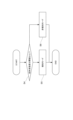
- the object discrimination unit 44 first calculates a variation value indicating the variation of the speed distribution, which is the speed information, such as the variance or standard deviation (S1). Then, by comparing this variation value with a threshold, it determines whether the object about to enter the specified area P is a car or not (S2). Specifically, if the variation value is below the threshold, it determines that the object is a vehicle (S3), and if the variation value exceeds the threshold, it determines that the object is not a vehicle, and outputs the discrimination result as discrimination information to the presence/absence determination unit 47 described later.
- a variation value indicating the variation of the speed distribution which is the speed information, such as the variance or standard deviation (S1). Then, by comparing this variation value with a threshold, it determines whether the object about to enter the specified area P is a car or not (S2). Specifically, if the variation value is below the threshold, it determines that the object is a vehicle (S3), and if the variation value exceeds the threshold, it determines that
- the object discrimination unit 44 may be configured to detect peaks that appear in the speed distribution, for example, and determine whether an object is a vehicle by comparing the number or height of the peaks with a threshold value.
- the reflection intensity information acquisition unit 45 acquires reflection intensity information that indicates the intensity of the reflected wave from the object. Specifically, it acquires the amplitude value of the beat signal received by the signal reception unit 42 as reflection intensity information, and outputs it to the presence/absence determination unit 47, which will be described later.
- the distance information acquisition unit 46 acquires distance information indicating the distance to an object based on the reflected wave from the object, and acquires the distance information by performing signal processing on the beat signal received by the signal reception unit 42. Specifically, the distance information acquisition unit 46 calculates the distance to the object by subjecting the beat signal to frequency analysis such as Fourier transform, and outputs the distance information to the presence/absence determination unit 47, which will be described later.
- the speed information, reflection intensity information, and distance information are information acquired using a single transmitter and a single receiver 20, as described above, in other words, information obtained by the SISO (Single Input Single Output) method.
- SISO Single Input Single Output
- the presence/absence determination unit 47 determines whether or not an object is present in the specified area P based on the reflection intensity information and distance information obtained by the SISO method.
- the presence/absence determination unit 47 of this embodiment is configured to determine the presence or absence of a vehicle in the specified area P when the above-mentioned object discrimination unit 44 determines that the object entering the specified area P is a vehicle.
- the presence/absence determination unit 47 is configured to determine the direction from which the reflected wave has returned based on the intensity (reception level) of the reflected wave indicated by the reflection intensity information, and here it determines whether the intensity of the reflected wave is equal to or greater than a threshold value (S4).
- the presence/absence determination unit 47 goes into detection mode to detect a vehicle in the specified area P, as shown in FIG. 10, and starts determining whether a vehicle is present in the specified area P (S5).
- the presence/absence determination unit 47 stops the vehicle detection operation for the specified area P and goes into non-detection mode, and does not determine whether a vehicle is present in the specified area P (S6).
- the presence/absence determination unit 47 determines whether or not a vehicle is present in the specified area P based on the distance information.
- the presence/absence determination unit 47 determines that a vehicle is present in the specified area P, and if the distance indicated by the distance information exceeds the threshold, the presence/absence determination unit 47 determines that a vehicle is not present in the specified area P, in other words, that the vehicle has left the specified area P.
- the presence/absence determination unit 47 outputs presence/absence information indicating the above-mentioned determination result to a control device C that controls the operation of a movable gate G and the like provided in the vicinity of the specified area P, and the control device C, for example, raises and lowers or opens and closes the movable gate G based on the received presence/absence information.
- the vehicle detection sensor 100 configured in this manner can determine whether an object is a vehicle based on the speed information obtained by the SISO method, and can determine whether an object is in a specified area P based on the reflection intensity information and distance information obtained by the SISO method. This means that there is no need to use an expensive MIMO type sensor, and a vehicle detection sensor 100 with high detection accuracy can be provided at low cost.
- the presence or absence of an object is determined based on both reflection intensity information and distance information, there is more information to be considered than if the determination was based on either reflection intensity information or distance information alone, making it possible to more reliably determine the presence or absence of an object in the specified area P.
- a stable reflection intensity can be obtained from a vehicle present in the specified area P, making it easier to determine whether or not an object is present, and by emitting a transmission wave toward the forward area Pf or the rearward area Pb, speed information can be obtained to determine whether or not an object is a vehicle.
- the transmission waves directed toward the specified area P and the forward area Pf and rearward area Pb are emitted from a common transmitter, and the reflected waves that are reflected back from objects are received by a common receiver 20. This means that only one set of transmitter/receiver is required, further reducing the cost of the sensor.
- the transmission and reception pattern indicating the transmission and reception antenna gain has a first peak that appears in the front direction and a quasi-peak that appears at a different angle from the front direction, and since a difference in intensity is generated between the first peak and the quasi-peak, it becomes possible to determine whether the received reflected wave has returned from a specified area P or from the forward area Pf or the rearward area Pb. This makes it possible to accurately determine whether or not a vehicle is present in a specified area P, even in an environment where the road width is wide, for example.
- the transmission and reception pattern has quasi-peaks on both the high-angle side and the low-angle side of the first peak, it is possible to determine whether an object is a vehicle both for an object approaching the predetermined area P and for an object moving away from the predetermined area P.
- detecting the speed of a moving object in the direction of receding may be used as one of the criteria for determining that a vehicle has left the predetermined area P, thereby improving the accuracy of the exit determination.
- the vehicle detection sensor 100 according to the present invention can be used for both the left lane and the right lane.
- the dielectric lens 50 that refracts a portion of the transmission wave emitted from the transmitter and directs it to the forward area Pf or the rear area Pb, it is possible to increase the radiation power of the transmission wave directed toward the forward area Pf or the rear area Pb, and it is possible to easily realize a configuration for emitting a transmission wave to a specified area P while also emitting a transmission wave to the forward area Pf or the rear area Pb by using the dielectric lens 50.
- the present invention is not limited to the above embodiment.
- the presence/absence determination unit 47 determines whether an object is present in the specified area P based on both reflection intensity information and distance information, but if the installation environment is one in which the presence/absence can be determined relatively easily, such as an environment in which the road width is narrow, the presence/absence determination unit 47 may be configured to determine whether an object is present in the specified area P based on either reflection intensity information or distance information.
- a transmission/reception pattern having a first peak and a quasi-peak is obtained by using a dielectric lens 50.
- a transmission/reception pattern having a first peak and a quasi-peak may be obtained without using a dielectric lens 50.
- the dielectric lens 50 is used to refract both the transmitted wave and the reflected wave, but the dielectric lens 50 may be configured to refract only one of the transmitted wave or the reflected wave.
- the dielectric lens 50 may refract a portion of the transmitted wave emitted from the transmitter 10 and guide it to the forward area Pf or the rearward area Pb, may refract a portion of the reflected wave returning from the forward area Pf or the rearward area Pb and guide it to the receiver 20, or may refract both the transmitted wave and the reflected wave.
- the vehicle detection sensor 100 outputs presence/absence information to a control device C that controls the operation of the movable gate G, but it may also output presence/absence information to, for example, an alarm device that sounds an alarm when a vehicle leaves the garage.
- a common transmitter emits a transmission wave toward the specified area P and the front area Pf or the rear area Pb
- a common receiver 20 is used to receive the reflected waves returning from the specified area P and the front area Pf or the rear area Pb.
- a separate SISO transmitter may emit a transmission wave toward the specified area P and the front area Pf or the rear area Pb
- a separate SISO receiver 20 may be used to receive the reflected waves returning from the specified area P and the front area Pf or the rear area Pb.
- the present invention makes it possible to provide an inexpensive vehicle detection sensor with high detection accuracy that can distinguish between vehicles and pedestrians and detect the entry and exit of vehicles into a specified area.
Landscapes
- Engineering & Computer Science (AREA)
- Radar, Positioning & Navigation (AREA)
- Remote Sensing (AREA)
- Physics & Mathematics (AREA)
- General Physics & Mathematics (AREA)
- Computer Networks & Wireless Communication (AREA)
- Electromagnetism (AREA)
- Chemical & Material Sciences (AREA)
- Analytical Chemistry (AREA)
- Computer Security & Cryptography (AREA)
- Radar Systems Or Details Thereof (AREA)
Abstract
Description
これならば、反射強度情報及び距離情報の双方に基づいて物体の存否を判断するので、反射強度情報又は距離情報の一方に基づいた判断よりも判断材料が多くなり、所定エリアにおける物体の存否をより確実に判断することができる。
これならば、所定エリアに向かって送信波を発射することで、所定エリアに存在する車両から安定した反射強度を得ることができ、存否の判断が容易になり、且つ、前方エリア又は後方エリアに向かって送信波を発射することで、物体が車両であるか否かを判別するための速度情報を得ることができる。
そこで、前記所定エリアに向かう送信波と、前記前方エリア又は前記後方エリアに向かう送信波とが、共通の送信器から発射されるとともに、それらの送信波が物体で反射して戻ってきた反射波それぞれが、共通の受信器で受信されることが好ましい。
これならば、1組の送受信器を用いる実施態様となり、センサのさらなる低コスト化を図れる。
これならば、第1ピークと準ピークとに強度差を生じさせているので、受信した反射波が所定エリアから戻ってきたものであるか、前方エリア又は後方エリアから戻ってきたものであるかを判別することができるようになる。これにより、例えば車路幅が広い環境においても、所定エリアにおける車両の存否を正確に判断することが可能となる。
これならば、所定エリアに近づく物体に対しても所定エリアから遠のく物体に対しても、車両であるか否かを判別することができる。これにより、例えば移動する物体の遠のく方向の速度を検出することを、所定エリアから車両が退出したと判断する基準の1つとして用いることで、退出判断の精度を向上させることができる。
また、上述した構成であれば、本発明に係る車両検知センサを左側車線用及び右側車線用として兼用することができる。
これならば、前方エリア又は後方エリアに向かう送信波の放射電力を増大させることができ、所定エリアに送信波を発射しつつ、前方エリア又は後方エリアにも送信波を発射するための構成を、誘電体レンズの利用によって簡易に実現することが可能となる。
なお、誘電体レンズを利用する技術分野において、通常は第1ピークを急峻にさせることが技術常識であるところ、第1ピークとは別の準ピークを現れるようにすることは、本発明ならではのアイディアである。
このように構成された車両検知センサ用プログラムであれば、上述した車両検知センサと同様の作用効果を奏し得る。
なお、図5において、太い実線が本実施形態における車両検知センサ100の送受信パターンであり、細い実線は後述する比較例である。
以下では、各部の説明を兼ねて、制御器40の動作を説明する。
これにより、例えば車路幅が広い環境においても、所定エリアPにおける車両の存否を正確に判断することが可能となる。
また、上述した構成であれば、本発明に係る車両検知センサ100を左側車線用及び右側車線用として兼用することができる。
P ・・・所定エリア
Pf ・・・前方エリア
Pb ・・・後方エリア
G ・・・可動ゲート
10 ・・・発信器
11 ・・・送信アンテナ
12 ・・・電圧制御発振器
20 ・・・受信器
21 ・・・受信アンテナ
30 ・・・ミキサ
40 ・・・制御器
41 ・・・制御信号生成部
42 ・・・信号受付部
43 ・・・速度情報取得部
44 ・・・物体判別部
45 ・・・反射強度情報取得部
46 ・・・距離情報取得部
47 ・・・存否判断部
C ・・・制御装置
50 ・・・誘電体レンズ
51 ・・・壁面
52 ・・・電波通過路
B ・・・基板
Claims (8)
- 車両が出入りする敷地の所定箇所に設置されて、時間経過に伴い周波数が変化する送信波を発射するとともに、その送信波が物体で反射して戻ってきた反射波を受信する車両検知センサであって、
前記反射波に基づいて、所定エリアに近づいてくる或いは前記所定エリアから遠のく物体の速度に関する速度情報を取得する速度情報取得部と、
前記速度情報に基づいて、物体が車両であるか否かを判別する物体判別部と、
前記反射波の強度を示す反射強度情報、又は、前記反射波に基づき得られる物体までの距離を示す距離情報の少なくとも一方に基づいて、物体が前記所定エリアにいるか否かを判断する存否判断部とを備え、
前記速度情報と、前記反射強度情報又は前記距離情報の少なくとも一方とが、SISO(Single Input Single Output)方式により得られる情報であることを特徴とする車両検知センサ。 - 前記反射強度情報を取得する反射強度情報取得部と、
前記距離情報を取得する距離情報取得部とを備え、
前記存否判断部が、前記反射強度情報、及び、前記距離情報に基づいて、物体が前記所定エリアにいるか否かを判断することを特徴とする請求項1記載の車両検知センサ。 - 前記所定エリアに向かって送信波を発射するとともに、前記所定エリアから車両の出入り方向に沿った前方又は後方に離れた前方エリア又は後方エリアに向かって送信波を発射するように構成されていることを特徴とする請求項1記載の車両検知センサ。
- 前記所定エリアに向かう送信波と、前記前方エリア又は前記後方エリアに向かう送信波とが、共通の送信器から発射されるとともに、それらの送信波が物体で反射して戻ってきた反射波それぞれが、共通の受信器で受信されることを特徴とする請求項3記載の車両検知センサ。
- 送信波の放射角度に対応する前記送信器の送信アンテナ利得と、反射波の受信角度に対応する前記受信器の受信アンテア利得とを合成してなる送受信アンテナ利得を示す送受信パターンが、正面方向に現れる第1ピークと、その正面方向とは別の角度に現れて前記第1ピークよりも小さい準ピークとを有する、請求項4記載の車両検知センサ。
- 前記送受信パターンが、前記第1ピークの高角度側及び低角度側のそれぞれに前記準ピークを有する、請求項5記載の車両検知センサ。
- 前記送信器から発射される送信波の一部を屈折させて前記前方エリア又は前記後方エリアに導く誘電体レンズを備える、請求項4記載の車両検知センサ。
- 車両が出入りする敷地の所定箇所に設置されて、時間経過に伴い周波数が変化する送信波を発射するとともに、その送信波が物体で反射して戻ってきた反射波を受信する車両検知センサに用いられるプログラムであって、
前記反射波に基づいて、所定エリアに近づいてくる或いは前記所定エリアから遠のく物体の速度に関する速度情報を取得する速度情報取得部と、
前記速度情報に基づいて、物体が車両であるか否かを判別する物体判別部と、
前記反射波の強度を示す反射強度情報、又は、前記反射波に基づき得られる物体までの距離を示す距離情報の少なくとも一方に基づいて、物体が前記所定エリアにいるか否かを判断する存否判断部としての機能をコンピュータに発揮させるものであり、
前記速度情報と、前記反射強度情報又は前記距離情報の少なくとも一方とが、SISO(Single Input Single Output)方式により得られる情報であることを特徴とする車両検知センサ用プログラム。
Priority Applications (3)
| Application Number | Priority Date | Filing Date | Title |
|---|---|---|---|
| JP2024555388A JP7724982B2 (ja) | 2023-06-09 | 2023-06-09 | 車両検知センサ及び車両検知センサ用プログラム |
| EP23937739.3A EP4528329A4 (en) | 2023-06-09 | 2023-06-09 | VEHICLE DETECTION SENSOR AND PROGRAM FOR VEHICLE DETECTION SENSOR |
| PCT/JP2023/021582 WO2024252677A1 (ja) | 2023-06-09 | 2023-06-09 | 車両検知センサ及び車両検知センサ用プログラム |
Applications Claiming Priority (1)
| Application Number | Priority Date | Filing Date | Title |
|---|---|---|---|
| PCT/JP2023/021582 WO2024252677A1 (ja) | 2023-06-09 | 2023-06-09 | 車両検知センサ及び車両検知センサ用プログラム |
Publications (1)
| Publication Number | Publication Date |
|---|---|
| WO2024252677A1 true WO2024252677A1 (ja) | 2024-12-12 |
Family
ID=93795835
Family Applications (1)
| Application Number | Title | Priority Date | Filing Date |
|---|---|---|---|
| PCT/JP2023/021582 Ceased WO2024252677A1 (ja) | 2023-06-09 | 2023-06-09 | 車両検知センサ及び車両検知センサ用プログラム |
Country Status (3)
| Country | Link |
|---|---|
| EP (1) | EP4528329A4 (ja) |
| JP (1) | JP7724982B2 (ja) |
| WO (1) | WO2024252677A1 (ja) |
Citations (9)
| Publication number | Priority date | Publication date | Assignee | Title |
|---|---|---|---|---|
| JPS55137378U (ja) * | 1979-03-23 | 1980-09-30 | ||
| JPS57201980U (ja) * | 1981-06-19 | 1982-12-22 | ||
| JPH07110375A (ja) * | 1993-10-13 | 1995-04-25 | Opt Kk | 誘電体レンズを用いた物体検知センサ |
| JP2009104654A (ja) * | 2003-06-05 | 2009-05-14 | Mitsubishi Electric Corp | 無線通信システム、および路車間通信方法 |
| JP2016072806A (ja) * | 2014-09-30 | 2016-05-09 | 日本ピラー工業株式会社 | アンテナ装置及びレドーム |
| JP2016148515A (ja) * | 2015-02-10 | 2016-08-18 | 株式会社豊田中央研究所 | レーダ装置 |
| JP2019032285A (ja) * | 2017-08-09 | 2019-02-28 | 株式会社デンソーテン | レーダ装置および物標検知方法 |
| JP6811065B2 (ja) | 2016-09-27 | 2021-01-13 | アマノ株式会社 | 車両検出装置及びゲート装置 |
| JP2021182195A (ja) * | 2020-05-18 | 2021-11-25 | 株式会社東海理化電機製作所 | 管理システム及び管理方法 |
Family Cites Families (3)
| Publication number | Priority date | Publication date | Assignee | Title |
|---|---|---|---|---|
| CN106199573B (zh) * | 2016-07-11 | 2019-10-18 | 芜湖森思泰克智能科技有限公司 | 用于道闸控制的侧向安装雷达 |
| JP6806247B2 (ja) * | 2017-05-17 | 2021-01-06 | 日本電気株式会社 | 物体検知装置、車載レーダシステム、監視レーダシステム、物体検知装置の物体検知方法及びプログラム |
| KR102100684B1 (ko) * | 2018-12-04 | 2020-04-14 | 김시석 | 레이더 장치를 이용한 주차장 출입통제 및 주차구역내 주차유무감지 장치 |
-
2023
- 2023-06-09 EP EP23937739.3A patent/EP4528329A4/en active Pending
- 2023-06-09 WO PCT/JP2023/021582 patent/WO2024252677A1/ja not_active Ceased
- 2023-06-09 JP JP2024555388A patent/JP7724982B2/ja active Active
Patent Citations (9)
| Publication number | Priority date | Publication date | Assignee | Title |
|---|---|---|---|---|
| JPS55137378U (ja) * | 1979-03-23 | 1980-09-30 | ||
| JPS57201980U (ja) * | 1981-06-19 | 1982-12-22 | ||
| JPH07110375A (ja) * | 1993-10-13 | 1995-04-25 | Opt Kk | 誘電体レンズを用いた物体検知センサ |
| JP2009104654A (ja) * | 2003-06-05 | 2009-05-14 | Mitsubishi Electric Corp | 無線通信システム、および路車間通信方法 |
| JP2016072806A (ja) * | 2014-09-30 | 2016-05-09 | 日本ピラー工業株式会社 | アンテナ装置及びレドーム |
| JP2016148515A (ja) * | 2015-02-10 | 2016-08-18 | 株式会社豊田中央研究所 | レーダ装置 |
| JP6811065B2 (ja) | 2016-09-27 | 2021-01-13 | アマノ株式会社 | 車両検出装置及びゲート装置 |
| JP2019032285A (ja) * | 2017-08-09 | 2019-02-28 | 株式会社デンソーテン | レーダ装置および物標検知方法 |
| JP2021182195A (ja) * | 2020-05-18 | 2021-11-25 | 株式会社東海理化電機製作所 | 管理システム及び管理方法 |
Non-Patent Citations (1)
| Title |
|---|
| See also references of EP4528329A4 |
Also Published As
| Publication number | Publication date |
|---|---|
| JPWO2024252677A1 (ja) | 2024-12-12 |
| JP7724982B2 (ja) | 2025-08-18 |
| EP4528329A1 (en) | 2025-03-26 |
| EP4528329A4 (en) | 2026-02-18 |
Similar Documents
| Publication | Publication Date | Title |
|---|---|---|
| US11947008B2 (en) | Distance measuring optoelectronic sensor and method for detecting a target object | |
| JP3385304B2 (ja) | 車載用レーダ装置 | |
| US8593333B2 (en) | Radar sensor with frontal and lateral emission | |
| CN104704385B (zh) | 物体检测装置 | |
| US9140780B2 (en) | Radar sensor having a blindness detection device | |
| JP3994941B2 (ja) | 車両用レーダ装置 | |
| KR100662063B1 (ko) | 스캔식 레이더의 정지물 검지(檢知) 방법 | |
| US5430450A (en) | Method and apparatus for automatically dimming motor vehicle headlights using radar signal | |
| KR100634107B1 (ko) | 레이더의 노상 정지물 검지 방법 | |
| US7151479B2 (en) | Radar sensor for motor vehicles | |
| CN110832340B (zh) | 用于探测运动对象的系统 | |
| US20090027180A1 (en) | Forward Object Sensor | |
| US10302760B2 (en) | Vehicle water detection system | |
| US6661370B2 (en) | Radar data processing apparatus and data processing method | |
| US10473760B2 (en) | Radar device and vertical axis-misalignment detecting method | |
| US8937571B2 (en) | Method and apparatus for detecting vehicle wheels | |
| KR102013224B1 (ko) | 긴급 제동 시스템 및 그 제어방법 | |
| RU2580947C2 (ru) | Способ и устройство детектирования колес | |
| CN105393135A (zh) | 机动车的雷达传感器的俯仰失调角的确定 | |
| JP2012512387A (ja) | 車両のためのfmcwレーダセンサ | |
| US6469656B1 (en) | Method of detecting moving and/or stationary objects in the path of a vehicle | |
| WO2011092814A1 (ja) | 障害物検出装置 | |
| KR20150051679A (ko) | 가변 파형을 이용하여 허위 타켓 판별하는 차량용 레이더 및 이를 이용한 허위 타겟 판별 방법 | |
| KR20180132853A (ko) | 자동차용 레이더 센서 장치, 운전자 보조 시스템, 자동차, 및 물체 감지 방법 | |
| US6507311B2 (en) | Device and process for measuring distance and speed |
Legal Events
| Date | Code | Title | Description |
|---|---|---|---|
| WWE | Wipo information: entry into national phase |
Ref document number: 2024555388 Country of ref document: JP |
|
| WWE | Wipo information: entry into national phase |
Ref document number: 2023937739 Country of ref document: EP |
|
| ENP | Entry into the national phase |
Ref document number: 2023937739 Country of ref document: EP Effective date: 20241216 |
|
| 121 | Ep: the epo has been informed by wipo that ep was designated in this application |
Ref document number: 23937739 Country of ref document: EP Kind code of ref document: A1 |
|
| NENP | Non-entry into the national phase |
Ref country code: DE |