WO2024252694A1 - 回転電機の電機子、回転電機、および、回転電機の電機子のリード線の製造方法 - Google Patents
回転電機の電機子、回転電機、および、回転電機の電機子のリード線の製造方法 Download PDFInfo
- Publication number
- WO2024252694A1 WO2024252694A1 PCT/JP2023/044768 JP2023044768W WO2024252694A1 WO 2024252694 A1 WO2024252694 A1 WO 2024252694A1 JP 2023044768 W JP2023044768 W JP 2023044768W WO 2024252694 A1 WO2024252694 A1 WO 2024252694A1
- Authority
- WO
- WIPO (PCT)
- Prior art keywords
- electric machine
- armature
- rotating electric
- lead wire
- wire
- Prior art date
- Legal status (The legal status is an assumption and is not a legal conclusion. Google has not performed a legal analysis and makes no representation as to the accuracy of the status listed.)
- Ceased
Links
Images










Classifications
-
- H—ELECTRICITY
- H02—GENERATION; CONVERSION OR DISTRIBUTION OF ELECTRIC POWER
- H02K—DYNAMO-ELECTRIC MACHINES
- H02K15/00—Processes or apparatus specially adapted for manufacturing, assembling, maintaining or repairing of dynamo-electric machines
- H02K15/06—Embedding prefabricated windings in the machines
-
- H—ELECTRICITY
- H02—GENERATION; CONVERSION OR DISTRIBUTION OF ELECTRIC POWER
- H02K—DYNAMO-ELECTRIC MACHINES
- H02K3/00—Details of windings
- H02K3/46—Fastening of windings on the stator or rotor structure
-
- H—ELECTRICITY
- H02—GENERATION; CONVERSION OR DISTRIBUTION OF ELECTRIC POWER
- H02K—DYNAMO-ELECTRIC MACHINES
- H02K3/00—Details of windings
- H02K3/46—Fastening of windings on the stator or rotor structure
- H02K3/52—Fastening salient pole windings or connections thereto
Definitions
- This disclosure relates to a rotating electric machine armature, a rotating electric machine, and a method for manufacturing a rotating electric machine armature lead wires.
- a conventional armature for a rotating electric machine is composed of a stator core having multiple magnetic pole teeth along its inner circumference, and windings wound around each magnetic pole tooth of the stator core via insulating members.
- a restraining portion is provided on the end face of the stator core to restrain the winding terminal.
- the restraining portion has a restraining groove that restrains the winding start terminal or the winding end terminal.
- the restraining groove also restrains the jumper wire that connects the winding start terminals together and also connects the power supply lead wire, and the jumper wire that connects the winding end terminals together and forms the neutral point.
- the restrained winding end and the jumper wire are connected by a metal piece that is fitted into the restraining portion.
- the jumper wire is formed into an arc and passes over each magnetic pole tooth to connect the desired windings, making it easy to connect the windings of the armature (see, for example, Patent Document 1).
- the jumper wires are formed into an arc, so for example, if a thick solid wire is used for the jumper wire, the high rigidity of the jumper wire makes it difficult to maintain its shape as the formed jumper wire springs back. As a result, when inserting the jumper wire into the restraining groove and wiring it along the magnetic pole teeth, it is necessary to wire it again along the desired shape, which creates the problem of poor workability.
- the conductor wire needs to be pressed into a mold that matches the shape, but a mold is needed for each jumper wire shape, which creates the problem of high mold costs.
- the crossover wire is not restrained midway when it is placed, it becomes unstable. For example, if it shifts when wiring another crossover wire or when inserting a metal piece into the restraining groove, it becomes necessary to reposition it to the desired position, which creates the problem that the time required for wiring the crossover wire cannot be reduced.
- This disclosure discloses technology to solve the problems described above, and aims to provide a rotating electric machine armature, a rotating electric machine, and a method for manufacturing the lead wires of a rotating electric machine armature that facilitates the wiring of lead wires, shortens the work time, and reduces investment costs.
- the armature of the rotating electric machine disclosed herein comprises: an armature core having a yoke portion formed in an annular shape and a plurality of teeth portions protruding radially inward from an inner periphery side of the yoke portion and formed at intervals in a circumferential direction; An insulating member provided on each of the teeth portions; a coil wound around the teeth via the insulating member; a lead wire electrically connected to at least one of a winding start end portion and a winding end end portion of the coil, The lead wire has a plurality of bent portions when viewed in the axial direction.
- the rotating electric machine disclosed herein is The present invention is provided with the above-described armature for a rotating electric machine.
- the present disclosure also provides a method for manufacturing a lead wire for an armature of a rotating electric machine, comprising the steps of: a feeding step of feeding out a reel-shaped wire by a preset length; and repeating the bending step of bending the wire at a preset angle.
- the wire is cut at a preset position to form the lead wire having a plurality of the bent portions.
- the lead wiring work can be easily performed, the work time can be shortened, and the investment cost can be reduced.
- FIG. 1 is a cross-sectional view showing a configuration of a rotating electric machine according to a first embodiment.
- 2 is a perspective view showing a configuration of a laminated core of the armature of the rotating electric machine shown in FIG. 1 .
- 3A is a perspective view showing the configuration of an insulator for the armature of the rotating electric machine shown in FIG. 1
- FIG. 3B is a perspective view showing the configuration of an insulator for the armature of the rotating electric machine shown in FIG. 2 is a perspective view showing a configuration of a winding assembly of an armature of the rotating electric machine shown in FIG. 1 ;
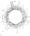
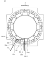
- 2 is a plan view of the armature of the rotating electric machine shown in FIG. 1 to which lead wires are wired.
- FIG. 6 is a plan view illustrating a process of wiring a lead wire to the armature of the rotating electric machine shown in FIG. 5 .
- 6 is a plan view illustrating a process of wiring a lead wire to the armature of the rotating electric machine shown in FIG. 5 .
- FIG. 7 is a perspective view illustrating a step of wiring another lead wire after the step shown in FIG. 6 .
- 5A to 5C are diagrams illustrating a manufacturing process for the lead wire of the armature of the rotating electric machine according to the first embodiment.
- 5A to 5C are diagrams illustrating a manufacturing process for the lead wire of the armature of the rotating electric machine according to the first embodiment.
- 5A to 5C are diagrams illustrating a manufacturing process for the lead wire of the armature of the rotating electric machine according to the first embodiment.
- 5A to 5C are diagrams illustrating a manufacturing process for the lead wire of the armature of the rotating electric machine according to the first embodiment.
- 5A to 5C are diagrams illustrating a manufacturing process for the lead wire of the armature of the rotating electric machine according to the first embodiment.
- 5A to 5C are diagrams illustrating a manufacturing process for the lead wire of the armature of the rotating electric machine according to the first embodiment.
- 5A to 5C are diagrams illustrating a manufacturing process for the lead wire of the armature of the rotating electric machine according to the first embodiment.
- 5A to 5C are diagrams illustrating a manufacturing process for the lead wire of the armature of the rotating electric machine according to the first embodiment.
- 5A to 5C are diagrams illustrating a manufacturing process for the lead wire of the armature of the rotating electric machine according to the first embodiment.
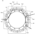
- FIG. 11 is a plan view showing a configuration of an armature for a rotating electric machine according to a second embodiment.
- 19 is a plan view illustrating a process for wiring a lead wire to the armature of the rotating electric machine shown in FIG. 18.
- 19 is a plan view illustrating a process for wiring a lead wire to the armature of the rotating electric machine shown in FIG. 18.
- FIG. 19 is a plan view illustrating a process for wiring a lead wire to the armature of the rotating electric machine shown in FIG. 18.
- 13 is a plan view illustrating a process for wiring another lead wire of the armature of the rotating electric machine according to the second embodiment.
- FIG. 5A to 5C are diagrams illustrating a manufacturing process for the lead wire of the armature of the rotating electric machine according to the first embodiment.
- 6 is a perspective view showing a configuration in which lead wires are fixed to the armature of the rotating electric machine shown in FIG. 5 by molding.
- Fig. 25A is a cross-sectional view showing a wire material forming a coil of a rotating electric machine according to embodiment 3.
- FIG. 25B is a cross-sectional view showing a wire material forming a lead wire and a crossover wire of a rotating electric machine according to embodiment 3.
- FIG. 25C is a cross-sectional view showing another wire material forming a lead wire and a crossover wire of a rotating electric machine according to embodiment 3.
- each direction in the rotating electric machine 100 is indicated as the circumferential direction Z, the axial direction Y, the radial direction X, the outer side X1 of the radial direction X, and the inner side X2 of the radial direction X. Therefore, these directions are the same in other parts as well, and each direction will be described based on these directions.
- Fig. 1 is a cross-sectional view showing the configuration of a rotating electric machine according to a first embodiment.
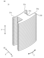
- Fig. 2 is a perspective view showing the configuration of a laminated core of an armature of the rotating electric machine shown in Fig. 1.
- Fig. 3 is a perspective view showing the configuration of an insulator of the armature of the rotating electric machine shown in Fig. 1
- Fig. 3A is a perspective view showing the configuration of an insulator on the connection side in the axial direction Y
- Fig. 3B is a perspective view showing the configuration of an insulator on the anti-connection side in the axial direction Y.
- Fig. 4 is a perspective view showing the configuration of a winding assembly of the armature of the rotating electric machine shown in Fig. 1.
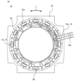
- FIG. 5 is a plan view of the lead wires wired to the armature of the rotating electric machine shown in FIG. 1.
- FIG. 6 is a plan view explaining the process of wiring the lead wires to the armature of the rotating electric machine shown in FIG. 5.
- FIG. 7 is a plan view explaining the process of wiring the lead wires to the armature of the rotating electric machine shown in FIG. 5.
- FIG. 8 is a perspective view explaining the process of wiring another lead wire after the process shown in FIG. 6.
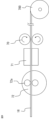
- FIGS. 9 to 17 and 23 are diagrams explaining the manufacturing process of the lead wires of the armature of the rotating electric machine according to embodiment 1.
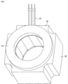
- FIG. 24 is a perspective view showing the configuration in which the lead wires are molded and fixed to the armature of the rotating electric machine shown in FIG. 5.
- the rotating electric machine 30 includes an armature 36 and a field element 37.
- the armature 36 includes a winding assembly 34 in which a coil 32 is wound around a laminated core 31 as an armature core via an insulator 33 as an insulating member, and the winding assembly 34 is arranged in an annular shape.
- the armature 36 is installed in a frame 35 by press-fitting or shrink-fitting.
- the field element 37 is arranged on the inner circumference side of the armature 36 and has a permanent magnet.
- the rotating electric machine further includes a bracket 38a on the connection side that holds the armature 36 and the field element 37, a bracket 38b on the non-connection side, and a power connector 39.
- the field element 37 is rotatably held by the brackets 38a and 38b by bearings (not shown).
- the laminated core 31 is formed of multiple electromagnetic steel sheets 310 stacked in the axial direction Y.
- a yoke portion 31a extending in the circumferential direction Z is formed on the outer peripheral side of the outer side X1 in the radial direction X of the laminated core 31.
- a tooth portion 31b protruding from the center position of the yoke portion 31a in the circumferential direction Z to the inner side X2 in the radial direction X is formed on the inner peripheral side of the inner side X2 in the radial direction X of the yoke portion 31a.
- a protrusion portion 31c extending on both sides in the circumferential direction Z is formed on each end of the inner side X2 in the radial direction X of the laminated core 31.
- the insulator 33 has two insulators 33a and 33b.
- the term "insulator 33" is used.
- the insulator 33a attached to the wiring side of the laminated core 31 in the axial direction Y includes an outer flange 33a1, an inner flange 33a2, and a body 33a3.
- the outer flange 33a1 includes a first restraining groove 33c and a second restraining groove 33d.
- the insulator 33b attached to the non-wiring side of the laminated core 31 in the axial direction Y includes an outer flange 33b1, an inner flange 33b2, and a body 33b3.
- the outer flanges 33a1, 33b1 of the insulators 33a, 33b cover the yoke portion 31a from both sides in the axial direction Y
- the inner flanges 33a2, 33b2 cover the protruding portion 31c from both sides in the axial direction Y
- the body portions 33a3, 33b3 cover the teeth portion 31b from both sides in the axial direction Y.
- the insulators 33a, 33b are attached to the laminated core 31, and the coil 32 is wound around the laminated core 31 to form the assembly.
- the coil 32 is wound around the teeth portion 31b via the insulators 33a, 33b.
- an insulating member such as an insulating film is disposed between both side surfaces of the laminated core 31 in the circumferential direction Z and the wound coil 32.
- the winding assembly 34 is formed by continuously winding the winding assembly 34 from the insulator 33b side on the anti-connection side around the laminated core 31 to which another insulator 33a, 33b is attached, and the coil 32 is formed by a set of continuous windings of the two winding assemblies 34.
- the winding assembly 34 is wound into a set of two continuous winding coils 32, this is not limited to this, and the coils may be wound with one winding assembly each, or, for example, the coil may be formed by continuously winding three winding assemblies.
- the coil terminal portion 32a of the coil 32 constituting the winding assembly 34 is inserted into the first restraining groove 33c of the insulator 33a on the connection side in the axial direction Y, and later, the terminal portion of the lead wire 14 is inserted into the second restraining groove 33d in a manner that protrudes from the radial inner side to the outer peripheral side of the outer flange portion 33a1. Then, the multiple winding assemblies 34 thus formed are arranged in a ring shape and fitted into the frame 35 by press fitting or shrink fitting, forming the armature 36.
- the coil 32 wound around the insulator 33 is electrically connected to the lead wire 14.
- the lead wire 14 is electrically connected to at least one of the start or end terminals of the coil 32, and in this case is a power line 14a that inputs the U, V, and W phases of three-phase AC from the outside to the coil 32, and a jumper wire 15 that serves as a neutral wire and connects between the coils 32.
- an input portion 14b which is the end of the power line 14a, is provided.
- the lead wire 14 When viewed from the axial direction Y, the lead wire 14 is disposed on the wound coil 32 of the insulator 33. Therefore, the folded portions 15c1, 15c2, 15c3, and 15c4 (see Figures 7 and 8) of the lead wire 14 described below are disposed in the area where the coil 32 is wound between the outer flange portion 33a1 and the inner flange portion 33a2 of the insulator 33. In the following description, any or all of the folded portions of the lead wire 14 may be referred to as folded portion 15c.
- the lead wire 14 is made of a conductive wire material such as highly conductive copper or aluminum covered with a highly insulating coating such as vinyl.
- the wire material may be a stranded wire, but a solid wire with high rigidity is better as it is easier to maintain the molded shape. It may also be made of a conductive wire material made of the same material as the coil 32, covered with an enamel coating to insulate it. Furthermore, a non-insulated conductive wire material may be used, but in that case, an insulating distance must be secured to ensure the insulating performance between the ground, between the coils 32, and between the lead wires 14.
- the cross section of the wire material may not only be circular, but also approximately rectangular.
- winding assemblies 34 are denoted by the reference numerals 34a, 34b, 34c, 34d, and 34e.
- one end 15a of the jumper wire 15 is inserted into the second restraining groove 33d provided in the insulator 33a of the winding assembly 34a. Then, a bent portion 15c1 is placed by bending the jumper wire 15 over the coil 32 of the winding assembly 34a. Next, the jumper wire 15 extends toward the upper portion of the coil 32 of the circumferentially adjacent winding assembly 34b. Then, a bent portion 15c2 is placed by bending the jumper wire 15 over the coil 32 of the winding assembly 34b. Then, the jumper wire 15 extends toward the upper portion of the coil 32 of the circumferentially adjacent winding assembly 34c.
- a bent portion 15c3 is placed on the top of the coil 32 of the winding assembly 34c.
- the jumper wire 15 extends to the top of the coil 32 of the circumferentially adjacent winding assembly 34d.
- a bent portion 15c4 is placed on the top of the coil 32 of the winding assembly 34d.
- the jumper wire 15 extends toward the second restraining groove 33d of the insulator 33a of the winding assembly 34d, and the other terminal portion 15b of the jumper wire 15 is inserted into the second restraining groove 33d of the insulator 33a of the winding assembly 34d.
- the jumper wire 15 when viewed from the axial direction Y, the jumper wire 15 is formed at four bent portions 15c1, 15c2, 15c3, and 15c4. These are the same as the number of coils 32 between which the jumper wire 15 is installed, i.e., the number of teeth portions 31b. Therefore, when installing the jumper wire 15, the installation positions of the bent portions 15c1, 15c2, 15c3, and 15c4 can be set to the coils 32 of the teeth portions 31b, improving the workability of installing the jumper wire 15. In addition, by checking the number of bent portions 15c1, 15c2, 15c3, and 15c4, the number of teeth portions 31b corresponding to the coils 32 to be connected can be ascertained, preventing mistakes in installing the jumper wire 15.
- the number of bent portions 15c of the lead wire 14 does not have to be the same as the number of teeth 31b, and it is sufficient that there is a maximum of one bent portion 15c arranged above the same teeth 31b.
- two bent portions may be provided. In that case, as shown in FIG. 23, there will be bent portions 15c16 and 15c17, or bent portions 15c17 and 15c18, which are bent twice in different directions in the circumferential direction Z.
- another jumper wire 15 is placed between the winding assembly 34d and the winding assembly 34e.
- One end of this jumper wire 15 is inserted into the second restraining groove 33d of the insulator 33a of the winding assembly 34d, and a bent portion 15c5 is placed by bending the jumper wire 15 over the coil 32 of the winding assembly 34d.
- the jumper wire 15 then extends over the coil 32 of the circumferentially adjacent winding assembly 34e.
- the bent portion 15c6 is placed by bending the coil 32 of the winding assembly 34e over the coil 32.
- the jumper wire 15 then extends toward the second restraining groove 33d of the insulator 33a, and the other end of the jumper wire 15 is inserted into the second restraining groove 33d of the insulator 33a of the winding assembly 34e.
- a conductive metal piece 60 is inserted into each of the restraining grooves 33c, 33d of the insulator 33a of the winding assemblies 34a, 34d, 34e to which the jumper wire 15 is wired, and installed.
- the metal piece 60 then contacts and conducts with the coil terminal portion 32a of the coil 32 and the terminal portions 15a, 15b of the jumper wire 15, thereby electrically connecting the jumper wire 15 and the coil 32.
- the excess terminal portions 15a, 15b are cut off, resulting in the connection state of Figure 6.
- the other jumper wires 15 and power supply wires 14a are then similarly connected in the state shown in Figure 5, completing the electrical connection between the coil 32 of the armature 36 and the lead wires 14.
- the field element 37, brackets 38a and 38b, and armature 36 shown in FIG. 1 are combined, and the input part 14b is inserted into the power connector 39 to produce the rotating electric machine 30.
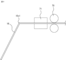
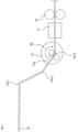
- the bending shaft 72 is rotated in the counterclockwise direction R1 to bend the wire 16 to a preset angle, forming the bent portion 15c1.
- the bending shaft 72 is retracted toward the back of the page to a position where it does not come into contact with the wire 16.
- the bending shaft 72 is retracted, it will attempt to return to the clockwise direction R2 due to springback, so if the wire is bent to a slightly larger angle in the state shown in FIG. 10 and then the bending shaft 72 is retracted, the accuracy of the bending will be improved.
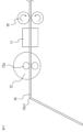
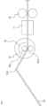
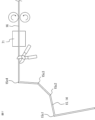
- the wire 16 is further fed by the feed shaft 70 a preset amount. Then, after rotating the bending shaft 72 until the position of the protrusion 72a is in the state shown in Figure 12, it moves towards the front side of the page, and the wire 16 passes between the protrusions 72a of the bending shaft 72. From this state, as shown in Figure 13, by rotating the bending shaft 72 in the clockwise direction R2, the wire 16 is bent to a preset angle on the upper side of the figure, forming the bent portion 15c2.
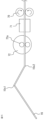
- the bending shaft 72 is returned in the counterclockwise direction R1, and after the bending shaft 72 is returned to the same state as in FIG. 12, the wire 16 is fed a preset length by the feed shaft 70 to the state shown in FIG. 15. Then, as shown in FIG. 16, the bending shaft 72 is rotated in the clockwise direction R2 to a preset angle, and the wire 16 is bent to form the bent portion 15c3. Thereafter, the wire is similarly fed to the desired bending position, and bending is repeated to the desired bending angle to form the bent portion 15c4, and the required shape of the lead wire 14 is formed as shown in FIG. 17, and the lead wire 14 is cut to the required length to form one of the crossover wires 15 shown in FIG. 7 in this case.
- multiple bent portions 15c1, 15c2, 15c3, and 15c4 can be automatically formed in sequence, improving the workability of manufacturing lead wires 14.
- lead wires 14 formed in a preset shape can be produced with one device simply by setting the feed amount and bending angle, reducing the number of types of jigs and minimizing the effort required for changeovers, improving the workability of forming lead wires 14.
- the coil terminal portion 32a of the coil 32 constituting the winding assembly 34 is inserted into the first restraining groove 33c, and the terminal portions 15a, 15b of the lead wire 14 are inserted into the second restraining groove 33d from the inside X2 to the outside X1 in the radial direction X of the outer flange portion 33a1, but this is not limited to this.
- the coil terminal portion 32a of the winding assembly 34d may be inserted into the second restraining groove 33d, or may be inserted into each restraining groove 33c, 33d in a position that is easy to insert.
- the coil terminal portion 32a and the terminal portions 15a, 15b of the lead wire 14 are electrically connected by inserting them into the respective restraining grooves 33c, 33d of the insulator 33a and placing the metal piece 60 to establish contact and conduction, but this is not limited to this.
- the coil terminal portion 32a and the terminal portions 15a, 15b of the lead wire 14 may be electrically connected by brazing, soldering, crimp terminals, or insulation displacement terminals.
- the lead wire 14 is not fixed at any portion other than the connection end. Note that the lead wire 14 may be fixed at any portion other than the connection end by a molded portion 41, as shown in FIG. 24.
- bent portions shown above are not formed on the outer side X1 of each insulator in the radial direction X. Furthermore, there are multiple bent portions for one lead wire shown above in the circumferential direction Z. Furthermore, the multiple bent portions for one lead wire shown above are not formed in overlapping positions in the axial direction Y.
- an armature core having a yoke portion formed in an annular shape and a plurality of teeth portions protruding radially inward from an inner periphery side of the yoke portion and formed at intervals in a circumferential direction;
- An insulating member provided on each of the teeth portions; a coil wound around the teeth via the insulating member; a lead wire electrically connected to at least one of a winding start end portion and a winding end end portion of the coil,
- the lead wire has a plurality of bent portions when viewed from the axial direction. Since the installation can be achieved simply by forming a bent portion in the lead wire, the wiring work of the lead wire can be easily performed, the work time can be shortened, and the investment cost can be reduced.
- the rotating electric machine of the first embodiment configured as described above, Since the above-described rotating electric machine armature is provided, Since the installation can be achieved simply by forming a bent portion in the lead wire, the wiring work of the lead wire can be easily performed, the work time can be shortened, and the investment cost can be reduced.
- the wire is cut at a preset position to form the lead wire having a plurality of the bent portions. Since the installation can be achieved simply by forming a bent portion in the lead wire, the wiring work of the lead wire can be easily performed, the work time can be shortened, and the investment cost can be reduced.
- the number of the bent portions of the lead wire is the same as the number of the teeth portions that are present between the bent portions and at least one of the winding start terminal portion and the winding end terminal portion of the coil when viewed from the axial direction.
- the bent portion of the lead wire is disposed in the area where the coil is wound as viewed from the axial direction. Furthermore, the lead wiring work can be easily performed, the work time can be shortened, and the investment cost can be reduced.
- the bent portions of the lead wires are arranged without being overlapped in the axial direction. Furthermore, the lead wiring work can be easily performed, the work time can be shortened, and the investment cost can be reduced.
- the lead wire is connected at its connection end to a terminal that is in contact with at least one of the winding start end portion and the winding end end portion of the coil, Furthermore, the lead wiring work can be easily performed, the work time can be shortened, and the investment cost can be reduced.
- the lead wire is not fixed at any part other than the connection end. Furthermore, the lead wiring work can be easily performed, the work time can be shortened, and the investment cost can be reduced.
- the lead wire is fixed by the molded part except for the connection end. Furthermore, the lead wiring work can be easily performed, the work time can be shortened, and the investment cost can be reduced.
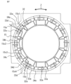
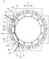
- FIG. 18 is a plan view showing the configuration of an armature for a rotating electric machine according to the second embodiment.
- Figures 19 to 21 are plan views for explaining the process of wiring the lead wires to the armature of the rotating electric machine shown in Figure 18.
- Figure 22 is a plan view for explaining the process of wiring another lead wire of the armature of the rotating electric machine according to embodiment 2.
- parts similar to those in embodiment 1 above are omitted by assigning the same reference numerals. Also, parts similar to those in embodiment 1 above will be explained using the same reference numerals. This also applies to the following embodiments, so explanations thereof will be omitted as appropriate.
- one end 15a of the jumper wire 151 is inserted into the second restraining groove 33d provided in the insulator 33a of the winding assembly 34a. Then, a bent portion 15c7 is placed by bending the jumper wire 15 in the vicinity of the outer flange portion 33a1 of the insulator 33a of the winding assembly 34a. Next, the jumper wire 15 extends to between the circumferential direction Z of the winding assemblies 34b and 34c adjacent in the circumferential direction. Then, a bent portion 15c8 is placed by bending the jumper wire 15 in the upper portion between the circumferential direction Z of the winding assemblies 34b and 34c.
- the jumper wire 15 extends to the vicinity of the outer flange portion 33a1 of the insulator 33a of the winding assembly 34d adjacent in the circumferential direction Z, and a bent portion 15c9 is placed by bending the jumper wire 15 in the vicinity of the outer flange portion 33a1 of the insulator 33a.
- the crossover wire 15 extends toward the second restraining groove 33d of the insulator 33a of the winding assembly 34d, and the other end portion 15b of the crossover wire 15 is inserted into the second restraining groove 33d of the insulator 33a of the winding assembly 34d.
- the upper part of the coil 32 of the winding assembly 34b and the upper part of the coil 32 of the winding assembly 34c do not have a bent portion. Therefore, according to the jumper wire 151 of the present embodiment 2, the number of bends can be reduced by one compared to the above embodiment 1, and the time required for the molding operation of the jumper wire 151 can be shortened.
- the jumper wire 151 is arranged via a path that contacts the inner flange portion 33a2 of the insulator 33a of the winding assembly 34b and the winding assembly 34c.
- another jumper wire 152 is placed between winding assembly 34d and winding assembly 34e.
- One end portion 15a of this jumper wire 152 is inserted into the second restraining groove 33d of the insulator 33a of winding assembly 34d, and a bent portion 15c10 is placed near the insulator 33a of winding assembly 34d.
- the jumper wire 15 then extends so as to contact the inner flange portion 33a2 of the insulator 33a of the winding assembly 34e adjacent in the circumferential direction Z.
- a bent portion 15c11 is placed near the inner flange portion 33a2 of the insulator 33a of winding assembly 34e.
- the crossover wire 15 extends toward the second restraining groove 33d of the insulator 33a, and the other end of the crossover wire 15 is inserted into the second restraining groove 33d of the insulator 33a of the winding assembly 34e.
- the crossover wire 152 is arranged via a path that brings it into contact with the inner flange portion 33a2 of the insulator 33a, so the position of the crossover wire 152 is stable, achieving the same effect as in the above case.
- the power lines 141 and 142 are bent fewer times than when they are bent at the top of the coils 32 of each winding assembly 34.
- the power line 141 is connected across six coils 32, but when viewed from the axial direction Y, there are only four bent parts: 14c1, 14c2, 14c3, and 14c4.
- the power line 142 is connected across three coils 32, but when viewed from the axial direction Y, there are only two bent parts: 14c5 and 14c6.
- the shapes of the power lines 141 and 142 are formed in this way, which shortens the forming work time.
- the power lines 141, 142 are routed through a path that contacts not only the inner flange 33a2 of the insulator 33a but also the outer flange 33a1 of the insulator 33a, making the positions of the power lines 141, 142 more stable.
- the number of bent points of the lead wire 14 when viewed from the axial direction Y is less than the number of teeth portions 31b (coils 32) that exist between the connection ends of the lead wire, so the forming work time of the lead wire 14 can be shortened.
- the lead wire 14 since the lead wire 14 has a portion that is arranged in contact with the insulator 33 other than the connection end, the position of the lead wire 14 after wiring is stable and is less likely to shift when placing another lead wire 14, improving wiring workability. Furthermore, the lead wire 14 does not shift even in material handling and subsequent processes after the wiring work, and there is no need to make any adjustments, so an inexpensive rotating electric armature can be provided.
- the shape of the lead wire 14 is not limited to this.
- bends 15c12, 15c13, 15c14, and 15c15 may be formed, and the jumper wire 151 may be wired via a route that contacts not only the inner flange 33a2 of the insulator 33a, but also the outer flange 33a1 of the insulator 33a. This configuration further stabilizes the position of the jumper wire 151.
- the same effects as those of the first embodiment can be obtained, and
- the number of the bent portions of the lead wire is smaller than the number of the teeth portions that are present between the bent portions and at least one of the winding start terminal portion and the winding end terminal portion of the coil when viewed from the axial direction.
- the lead wire has a portion other than the connection end that is in contact with the insulating member. Since the lead wires come into contact with the insulating member, the position of the lead wires can be stabilized, shortening the wiring work time. In addition, even after wiring, the lead wires do not shift during material handling or post-processing, and there is no need to make any adjustments, making it possible to provide an armature for an inexpensive rotating electric machine.
- Fig. 25A is a cross-sectional view showing wire material forming a coil of a rotating electric machine according to embodiment 3.
- Figs. 25B and 25C are cross-sectional views showing wire material forming a lead wire and a jumper wire of a rotating electric machine according to embodiment 3.
- the wire material forming the coil 32 of a rotating electric machine having the structure described in each of the above embodiments and the wire material forming the lead wire 14 and the jumper wire 15 will be described.
- the wire that forms the coil 32 is formed of a coil conductor 32c2 and an enamel coating 32c1 that covers the outer circumference of the coil conductor 32c2 with a thickness W1, as shown in Figure 25A.
- the wire that forms the lead wire 14 and the jumper wire 15 is formed of a solid wire 15d2 or a stranded wire 15d3 and an external coating 15d1 that covers the outer circumference of the solid wire 15d2 or the stranded wire 15d3 with a thickness W2 or W3, as shown in Figures 25B and 25C.
- the external coating 15d1 is formed of, for example, a fluororesin or PVC (polyvinyl chloride), and is stronger and more elastic than the enamel coating 32c1.
- the thicknesses W2 and W3 of the outer coating 15d1 are greater than the thickness W1 of the enamel coating 32c1 that covers the outer circumference of the coil conductor 32c2, the outer coating 15d1 is less likely to break than the enamel coating 32c1 of the coil 32 when forming the bent portion, ensuring insulation strength.
- the stranded wire 15d3 is easier to deform than the solid wire 15d2, so it has the advantage of requiring less force for the forming process. Note that the thickness W3 of the outer coating 15d1 in the case of the stranded wire 15d3 indicates the minimum distance from the outermost diameter part of the stranded wire 15d3 to the outer diameter of the outer coating 15d1.
- the same effects as those of the above-described embodiments can be obtained, and in addition,
- the thickness of the outer coating of the lead wire is thicker than the thickness of the outer coating of the coil, This ensures the insulation distance and the insulation strength. In addition, because it has excellent strength and elasticity, it is difficult to break and the insulation strength can be further ensured.
- the conductor which is the core of the lead wire, is made of a stranded wire. It is easier to deform than solid wire, making it excellent for forming work.
- an armature core having a yoke portion formed in an annular shape and a plurality of teeth portions protruding radially inward from an inner periphery side of the yoke portion and formed at intervals in a circumferential direction; An insulating member provided on each of the teeth portions; a coil wound around the teeth via the insulating member; a lead wire electrically connected to at least one of a winding start end portion and a winding end end portion of the coil, The lead wire is an armature for a rotating electric machine having a plurality of bent portions when viewed in the axial direction.
- Appendix 2 An armature for a rotating electric machine as described in Appendix 1, wherein the number of the bent portions of the lead wire, when viewed in the axial direction, is the same as the number of the teeth portions that exist between the lead wire and at least one of the winding start terminal portion or the winding end terminal portion of the coil and are electrically connected to the lead wire.
- Appendix 3 An armature for a rotating electric machine as described in Appendix 1, wherein the number of bent portions of the lead wire, when viewed in the axial direction, is less than the number of teeth portions that exist between the lead wire and at least one of the winding start terminal portion or the winding end terminal portion of the coil and are electrically connected to the lead wire.
- Appendix 4 4.
- a rotating electric machine comprising the rotating electric machine armature according to any one of claims 1 to 4.
- Appendix 6) a feeding step of feeding out a reel-shaped wire by a preset length; and repeating the bending step of bending the wire at a preset angle.
Landscapes
- Engineering & Computer Science (AREA)
- Power Engineering (AREA)
- Manufacturing & Machinery (AREA)
- Insulation, Fastening Of Motor, Generator Windings (AREA)
Abstract
環状に形成されたヨーク部(31a)と、ヨーク部(31a)の内周側から径方向(X)の内側(X2)に突出するとともに周方向(Z)に間隔を隔てて形成された複数のティース部(31b)とを有する電機子鉄心(31)と、各ティース部(31b)に設置された絶縁部材(33)と、絶縁部材(33)を介してティース部(31b)に巻回されたコイル(32)と、コイル(32)の巻始め端末部または巻終わり端末部の少なくともいずれか一方と電気的に接続されたリード線(149とを備え、リード線(14)は、軸方向(Y)から見ると、複数の折り曲げ部(15c1~15c4)を有する。
Description
本開示は、回転電機の電機子、回転電機、および、回転電機の電機子のリード線の製造方法に関するものである。
従来の回転電機の電機子は、内周部に沿って複数の磁極歯を有する固定子鉄心と、この固定子鉄心の各磁極歯に絶縁部材を介して巻回される巻線とから構成される。固定子鉄心の端面には、巻線端末部を拘束する拘束部が設けられている。拘束部には、拘束溝が設けられており、巻線の巻始め端末部、または、巻線の巻終わり端末部を拘束する。また、その拘束溝には、巻線の巻始め端末部どうしを接続し、さらに、電源側リード線を接続する渡り線、また、巻線の巻終わり端末部どうしを接続し、中性点を形成する渡り線も、拘束される。拘束された巻線の端末部および渡り線は、拘束部に嵌め込まれる金属片により、接続される。そして、渡り線が円弧に成形され、各磁極歯の上を通して所望の巻線間を接続することで電機子の巻線間の結線を容易にしている(例えば、特許文献1参照)。
従来の回転電機の電機子は、渡り線を円弧に成形されているために、例えば、渡り線に太い単線を用いた場合、渡り線の剛性が高く、成形した渡り線がスプリングバックにより戻ろうとすることで、形状を維持することが難しくなる。このため、渡り線を拘束溝に挿入し、磁極歯に沿わせて配線する作業時に再度所望の形状に沿わせて配線する必要があり、作業性が悪いという問題点があった。
また、渡り線を所望の形状にするために、その形状に合わせた成形型に導線を押し付けて成形する必要があるが、渡り線の形状ごとに成形型が必要となり、成形型の費用がかかるという問題点があった。
さらに、渡り線が配置された状態で、渡り線の途中が拘束されていないので、渡り線が不安定となり、例えば、別の渡り線を配線する際にズレたり、拘束溝への金属片の挿入の際にズレたりした場合に、所望の位置に配置しなおす作業が生じ、渡り線の配線作業時間を短縮できないという問題点があった。
また、配線した後にもマテリアルハンドリングおよび後工程での振動などで渡り線に外力がかかると渡り線が位置ズレまたは脱落が生じる可能性があり、手直しの手間がかかるという問題点があった。
本開示は、上記のような課題を解決するための技術を開示するものであり、リード線の配線作業が容易にでき、かつ、作業時間が短縮でき、かつ、投資費用が削減できる回転電機の電機子、回転電機、および、回転電機の電機子のリード線の製造方法を提供することを目的とする。
本開示される回転電機の電機子は、
環状に形成されたヨーク部と、前記ヨーク部の内周側から径方向の内側に突出するとともに周方向に間隔を隔てて形成された複数のティース部とを有する電機子鉄心と、
各前記ティース部に設置された絶縁部材と、
前記絶縁部材を介して前記ティース部に巻回されたコイルと、
前記コイルの巻始め端末部または巻終わり端末部の少なくともいずれか一方と電気的に接続されたリード線とを備えた回転電機の電機子において、
前記リード線は、軸方向から見ると、複数の折り曲げ部を有するものである。
また、本開示される回転電機は、
上記記載の回転電機の電機子を備えたものである。
また、本開示される回転電機の電機子のリード線の製造方法は、
リール状の線材をあらかじめ設置された長さ送り出す送り出し工程と、
前記線材をあらかじめ設定された角度で折り曲げる折り曲げ工程とを繰り返した後、
前記線材をあらかじめ設定された位置で切断し、複数の前記折り曲げ部を複数有する前記リード線を成形するものである。
環状に形成されたヨーク部と、前記ヨーク部の内周側から径方向の内側に突出するとともに周方向に間隔を隔てて形成された複数のティース部とを有する電機子鉄心と、
各前記ティース部に設置された絶縁部材と、
前記絶縁部材を介して前記ティース部に巻回されたコイルと、
前記コイルの巻始め端末部または巻終わり端末部の少なくともいずれか一方と電気的に接続されたリード線とを備えた回転電機の電機子において、
前記リード線は、軸方向から見ると、複数の折り曲げ部を有するものである。
また、本開示される回転電機は、
上記記載の回転電機の電機子を備えたものである。
また、本開示される回転電機の電機子のリード線の製造方法は、
リール状の線材をあらかじめ設置された長さ送り出す送り出し工程と、
前記線材をあらかじめ設定された角度で折り曲げる折り曲げ工程とを繰り返した後、
前記線材をあらかじめ設定された位置で切断し、複数の前記折り曲げ部を複数有する前記リード線を成形するものである。
本開示される回転電機の電機子、回転電機、および、回転電機の電機子のリード線の製造方法によれば、
リード線の配線作業が容易にでき、かつ、作業時間が短縮でき、かつ、投資費用が削減できる。
リード線の配線作業が容易にでき、かつ、作業時間が短縮でき、かつ、投資費用が削減できる。
以下の説明において、回転電機100における各方向を、それぞれ周方向Z、軸方向Y、径方向X、径方向Xの外側X1、径方向Xの内側X2として示す。よって、他の部分においても、これらの方向は同一方向となり、当該方向を基準として各方向を示して説明する。
実施の形態1.
図1は、実施の形態1による回転電機の構成を示す断面図である。図2は、図1に示した回転電機の電機子の積層コアの構成を示す斜視図である。図3は、図1に示した回転電機の電機子のインシュレータの構成を示す斜視図であり、図3Aは、軸方向Yの結線側のインシュレータの構成を示す斜視図、図3Bは、軸方向Yの反結線側のインシュレータの構成を示す斜視図である。図4は、図1に示した回転電機の電機子の巻線組立品の構成を示す斜視図。
図1は、実施の形態1による回転電機の構成を示す断面図である。図2は、図1に示した回転電機の電機子の積層コアの構成を示す斜視図である。図3は、図1に示した回転電機の電機子のインシュレータの構成を示す斜視図であり、図3Aは、軸方向Yの結線側のインシュレータの構成を示す斜視図、図3Bは、軸方向Yの反結線側のインシュレータの構成を示す斜視図である。図4は、図1に示した回転電機の電機子の巻線組立品の構成を示す斜視図。
図5は、図1に示した回転電機の電機子にリード線を配線した平面図である。図6は、図5に示した回転電機の電機子にリード線の配線の工程を説明する平面図である。図7は、図5に示した回転電機の電機子にリード線の配線の工程を説明する平面図である。図8は、図6に示した工程後の、別のリード線を配線する工程を説明する斜視図である。図9から図17および図23は、実施の形態1による回転電機の電機子のリード線の製造工程を説明する図である。図24は、図5に示した回転電機の電機子にモールドしてリード線を固定した構成を示す斜視図である。
図1に示すように、回転電機30は、電機子36と界磁子37とを備える。電機子36は、電機子鉄心としての積層コア31に絶縁部材としてのインシュレータ33を介してコイル32が巻回された巻線組立品34が環状に配置される。電機子36は、フレーム35に圧入または焼き嵌めして設置される。界磁子37は、電機子36の内周側に配置され永久磁石を有する。さらに、電機子36と界磁子37を保持する結線側のブラケット38aと、反結線側のブラケット38bと、電源コネクタ39を備えている。また、界磁子37は、図示しないベアリングによりブラケット38a、38bと回転可能に保持されている。
図2に示すように、積層コア31は、軸方向Yに積層される複数枚の電磁鋼板310によって形成される。積層コア31の径方向Xの外側X1の外周側には、周方向Zに延在したヨーク部31aが形成される。ヨーク部31aの径方向Xの内側X2の内周側には、ヨーク部31aの周方向Zの中央の位置から、径方向Xの内側X2に突出するティース部31bが形成される。積層コア31の径方向Xの内側X2の端部には、周方向Zの両側に広がる形状の突出部31cがそれぞれ形成される。
インシュレータ33は、図3に示すように、2つのインシュレータ33a、33bを有する。なお、いずれかのインシュレータまたは両方のインシュレータをさす場合には、インシュレータ33とのみ示す。図3Aに示すように、積層コア31の軸方向Yの結線側に装着されるインシュレータ33aは、外鍔部33a1、内鍔部33a2、および、胴部33a3を備える。外鍔部33a1には、第1拘束溝33c、および、第2拘束溝33dを備える。図3Bに示すように、積層コア31の軸方向Yの反結線側に装着されるインシュレータ33bは、外鍔部33b1、内鍔部33b2、および、胴部33b3を備える。
図4に示すように、巻線組立品34は、インシュレータ33a、33bの外鍔部33a1、33b1が、ヨーク部31aを軸方向Yの両側から覆い、内鍔部33a2、33b2は、突出部31cを軸方向Yの両側から覆い、胴部33a3、33b3は、ティース部31bを軸方向Yの両側から覆う。このように、積層コア31にインシュレータ33a、33bが装着され、かつコイル32が巻回され形成される。コイル32は、インシュレータ33a、33bを介してティース部31bに巻回される。また積層コア31の周方向Zの両側面と、巻回されるコイル32との間には、図示していないが、例えば絶縁フィルムなどの絶縁部材が配置される。
またここでは、巻線組立品34は、反結線側のインシュレータ33b側から、もう一つ別のインシュレータ33a、33bが装着された積層コア31に連続して巻回して巻線組立品34を形成し、2個の巻線組立品34で一組の連続巻きでコイル32が構成される。なお、巻線組立品34を2個一組の連続巻きのコイル32が巻回される例を示したが、これに限られることはなく、コイルを1個ずつの巻線組立品で巻回してもよいし、また、例えば、コイルを3個の巻線組立品を連続して巻回して構成してもよい。
軸方向Yの結線側のインシュレータ33aの第1拘束溝33cには、巻線組立品34をなすコイル32のコイル端末部32aが、第2拘束溝33dには、後に、リード線14の端末部が、外鍔部33a1の径方向内周側から外周側に突出する形で挿入される。そして、このように形成された複数の巻線組立品34が環状に配置され、圧入または焼嵌めによってフレーム35に嵌め込まれ、電機子36が形成される。
図5に示すように、インシュレータ33に巻線されたコイル32は、リード線14と電気的に接続される。リード線14は、コイル32の巻始め端末部または巻終わり端末部の少なくともいずれか一方と電気的に接続するものであり、ここでは、三相交流のU、V、W相を外部からコイル32に入力する電源線14a、および、中性線となりコイル32間を接続する渡り線15である。さらに、U、V、W相の電源線14aを電源コネクタ39へ接続するため、電源線14aの端部である入力部14bを備える。
なお、リード線14は軸方向Yから見て、インシュレータ33の巻線されたコイル32上に配置される。よって、インシュレータ33の外鍔部33a1と内鍔部33a2の間のコイル32が巻き回される領域上に、後述するリード線14の折り曲げ部15c1、15c2、15c3、15c4(図7および図8参照)が配置される。なお、以下の説明において、リード線14のいずれかの折り曲げ部または全ての折り曲げ部をさす場合には、折り曲げ部15cと示す場合もある。
リード線14は、導電性の高い銅またはアルミニウムなどの導電性を有する線材に絶縁性の高いビニールなどの被覆で覆ったもので構成されている。なお、線材はより線でもよいが、剛性の高い単線の方が成形形状を保ちやすくよい。また、コイル32と同じ材質の導電性を有する線材にエナメル皮膜を覆って絶縁したもので構成してもよい。さらに、絶縁していない導電性を有する線材でもよいが、その場合、対地間、コイル32間、リード線14間の絶縁性能を確保するため、絶縁距離を確保する必要がある。また、線材の断面は円だけでなく、略長方形でもよい。
次に、上記のように構成された実施の形態1の回転電機の電機子36の渡り線15を配線する工程について図6から図8を用いて説明する。なお、各図において、複数の巻線組立品34を区別するために、巻線組立品34a、34b、34c、34d、34eとそれぞれ符号を付して説明する。
まず、図7および図8に示すように、渡り線15の一方の端末部15aが巻線組立品34aのインシュレータ33aに設けられた第2拘束溝33dに挿入される。そして、巻線組立品34aのコイル32の上部で折り曲げられた折り曲げ部15c1が設置される。次に、周方向に隣接する巻線組立品34bのコイル32の上部の方向に渡り線15が延びる。そして、巻線組立品34bのコイル32の上部で折り曲げられた折り曲げ部15c2が設置される。そして、周方向に隣接する巻線組立品34cのコイル32の上部の方向に渡り線15が延びる。
さらに、巻線組立品34cのコイル32の上部で折り曲げられた折り曲げ部15c3が設置される。そして、周方向に隣接する巻線組立品34dのコイル32の上部に渡り線15が延びる。そして、巻線組立品34dのコイル32の上部で折り曲げられた折り曲げ部15c4が設置される。そして、巻線組立品34dのインシュレータ33aの第2拘束溝33dに向かい、渡り線15が延びていき、渡り線15のもう一方の端末部15bが巻線組立品34dのインシュレータ33aの第2拘束溝33dに挿入される。
ここでは、渡り線15は、軸方向Yから見ると、折り曲げ部15c1、15c2、15c3、15c4の4箇所形成している。これらは、渡り線15が設置される間に存在するコイル32の数、すなわちティース部31bの数と同一である。よって、渡り線15を設置する際に、この折り曲げ部15c1、15c2、15c3、15c4の設置位置を、ティース部31bのコイル32を目標として行うことができるため、渡り線15の設置に対する作業性が向上できる。また、この折り曲げ部15c1、15c2、15c3、15c4の数を確認することで、接続するコイル32間に対応するティース部31bの数を把握できるため、渡り線15の設置間違いを防止できる。
ただし、リード線14の折り曲げ部15cの個数は、ティース部31bと同一の数でなくてもよく、同じティース部31bの上部で最大1個となるように配置されていればよい。ただし、図23に示すように、リード線14にて周方向Zに隣り合うティース部31bを接続する場合には、2個の折り曲げ部を有してもよい。その場合、図23に示すように、周方向Zに異なる方向に2回曲げた折り曲げ部15c16および折り曲げ部15c17、または、折り曲げ部15c17および折り曲げ部15c18を有することとなる。
次に、図6に示すように、巻線組立品34dと巻線組立品34eとの間に、別の渡り線15を配置する。この渡り線15は、一方の端末部が巻線組立品34dのインシュレータ33aの第2拘束溝33dに挿入され、巻線組立品34dのコイル32の上部で折り曲げられた折り曲げ部15c5が設置される。そして、周方向に隣接する巻線組立品34eのコイル32の上部に渡り線15が延びる。そして、巻線組立品34eのコイル32の上部で折り曲げられた折り曲げ部15c6が設置される。そして、インシュレータ33aの第2拘束溝33dに向かい、渡り線15が延びていき、渡り線15のもう一方の端末部が巻線組立品34eのインシュレータ33aの第2拘束溝33dに挿入される。
そして、この状態で、導電性の金属片60を渡り線15が配線された巻線組立品34a、34d、34eのインシュレータ33aの各拘束溝33c、33dに挿入して設置する。そして、当該金属片60により、コイル32のコイル端末部32a、および、渡り線15の端末部15a、15bに接触、導通させることで、渡り線15とコイル32とを電気的に接続する。さらに、図7および図8に示すような、余分な端末部15a、15bを切断し、図6の結線状態となる。そして、その他の渡り線15、電源線14aも同様に、図5に示す状態に結線することで、電機子36のコイル32とリード線14との電気的な接続が完了する。この後、図1に示す界磁子37とブラケット38a、38bと電機子36を組み合わせ、電源コネクタ39に入力部14bを挿入することで、回転電機30が製作される。
次に、上記のように構成されるリード線14の製造方法について図9から図17を交えて説明する。まず、図9に示すように、送り軸70によりリール700から巻き取られた線材16が、ガイド71および曲げ軸72に設けられた2つの円筒形の突起部72aの間を通って送出される。
次に、図10に示すように、曲げ軸72を反時計回り方向R1に回転させることで、線材16をあらかじめ設定された角度に曲げ、折り曲げ部15c1を形成する。次に、図11に示すように、曲げ軸72が線材16に当たらない位置まで紙面奥側に退避させる。この際、剛性が高い太い単線を用いた場合、曲げ軸72を退避した時点で、スプリングバックにより時計回り方向R2に戻ろうとするので、図10の状態で少し大きめの角度に曲げてから、曲げ軸72を退避すれば、折り曲げの精度が向上する。
次に、図12に示すように、さらに線材16を送り軸70によりあらかじめ設定された量だけ送る。そして、曲げ軸72の突起部72aの位置が図12に示す状態まで回転させた後、紙面手前側に移動し、線材16が曲げ軸72の突起部72aの間を通った状態にする。この状態から、図13に示すように、時計回り方向R2に曲げ軸72を回転させることで、線材16を図の上方向側のあらかじめ設定された角度まで曲げ、折り曲げ部15c2を形成する。
次に、図14に示すように、曲げ軸72を反時計回り方向R1に戻し、曲げ軸72を図12と同様の状態まで戻した後、線材16を送り軸70であらかじめ設定された長さ送って、図15に示すような状態にする。そして、曲げ軸72を、図16に示すように、あらかじめ設定された角度まで時計回り方向R2に回転させ、線材16を折り曲げ、折り曲げ部15c3を形成する。以降、同様に、曲げたい箇所まで送り、曲げたい角度に曲げを繰り返し、折り曲げ部15c4を形成し、図17に示すように、必要なリード線14の形状が成形され、必要な長さで切断してリード線14、ここでは図7に示した一方の渡り線15を形成する。
このように、実施の形態1の回転電機30の電機子36によれば、リード線14を折り曲げて成形するために、リード線14に剛性が高い太い単線を用いた場合でも、剛性を考慮して、少し折り曲げ角度を大きく設定することで、スプリングバックによりあらかじめ設定された形状に成形することができ、成形後のリード線14の形状精度を高めることができる。
また、図9から図17に示す装置で、複数の折り曲げ部15c1、15c2、15c3、15c4を自動的に順番に成形でき、リード線14の製作作業性が向上する。さらに、図9から図17の作り方によれば、形状の異なる複数類の渡り線15を成形する場合でも、送り量と曲げの角度とを設定するだけで、1つの装置であらかじめ設定された形状に成形したリード線14を製作でき、治具の種類を削減でき、段取り替えの手間も抑制できるので、リード線14の成形作業性を向上できる。
さらに、第1拘束溝33cには、巻線組立品34をなすコイル32のコイル端末部32aが、第2拘束溝33dには、リード線14の端末部15a、15bが、外鍔部33a1の径方向Xの内側X2から外側X1に挿入される例を示したが、これに限られるものではなく、例えば、図6の巻線組立品34aのコイル端末部32aを第1拘束溝33cに入れ、巻線組立品34dのコイル端末部32aを第2拘束溝33dに入れてもよく、入れやすい位置の各拘束溝33c、33dに入れて構成してもよい。
また、コイル端末部32aとリード線14の端末部15a、15bをインシュレータ33aの各拘束溝33c、33dへ挿入し、金属片60を設置して接触導通させることで電気的に接続する例を説明したが、これに限られることはなく、例えば、ろう付け、はんだ付け、圧着端子もしくは圧接端子により、コイル端末部32aとリード線14の端末部15a、15bとを電気的に接続してもよい。また、リード線14は、接続端部以外の部分においては固定されていない。なお、リード線14は、図24に示すように、リード線14の接続端部以外の部分をモールド部41によって固定してもよい。
なお、先に示した各折り曲げ部は、各インシュレータより径方向Xの外側X1には形成されていない。また、先に示した1つのリード線に対する折り曲げ部は、周方向Zに複数存在する。また、先に示した1つのリード線に対する複数の折り曲げ部は、軸方向Yにおいて、重なった位置に形成されることはない。
上記のように構成された実施の形態1の回転電機の電機子によれば、
環状に形成されたヨーク部と、前記ヨーク部の内周側から径方向の内側に突出するとともに周方向に間隔を隔てて形成された複数のティース部とを有する電機子鉄心と、
各前記ティース部に設置された絶縁部材と、
前記絶縁部材を介して前記ティース部に巻回されたコイルと、
前記コイルの巻始め端末部または巻終わり端末部の少なくともいずれか一方と電気的に接続されたリード線とを備えた回転電機の電機子において、
前記リード線は、軸方向から見ると、複数の折り曲げ部を有するので、
リード線に折り曲げ部を形成するのみで設置可能となるため、リード線の配線作業が容易にでき、かつ、作業時間が短縮でき、かつ、投資費用が削減できる。
環状に形成されたヨーク部と、前記ヨーク部の内周側から径方向の内側に突出するとともに周方向に間隔を隔てて形成された複数のティース部とを有する電機子鉄心と、
各前記ティース部に設置された絶縁部材と、
前記絶縁部材を介して前記ティース部に巻回されたコイルと、
前記コイルの巻始め端末部または巻終わり端末部の少なくともいずれか一方と電気的に接続されたリード線とを備えた回転電機の電機子において、
前記リード線は、軸方向から見ると、複数の折り曲げ部を有するので、
リード線に折り曲げ部を形成するのみで設置可能となるため、リード線の配線作業が容易にでき、かつ、作業時間が短縮でき、かつ、投資費用が削減できる。
また、上記のように構成された実施の形態1の回転電機によれば、
上記記載の回転電機の電機子を備えたので、
リード線に折り曲げ部を形成するのみで設置可能となるため、リード線の配線作業が容易にでき、かつ、作業時間が短縮でき、かつ、投資費用が削減できる。
上記記載の回転電機の電機子を備えたので、
リード線に折り曲げ部を形成するのみで設置可能となるため、リード線の配線作業が容易にでき、かつ、作業時間が短縮でき、かつ、投資費用が削減できる。
また、上記のように行われた実施の形態1の回転電機の電機子のリード線の製造方法によれば、
リール状の線材をあらかじめ設置された長さ送り出す送り出し工程と、
前記線材をあらかじめ設定された角度で折り曲げる折り曲げ工程とを繰り返した後、
前記線材をあらかじめ設定された位置で切断し、複数の前記折り曲げ部を複数有する前記リード線を成形するので、
リード線に折り曲げ部を形成するのみで設置可能となるため、リード線の配線作業が容易にでき、かつ、作業時間が短縮でき、かつ、投資費用が削減できる。
リール状の線材をあらかじめ設置された長さ送り出す送り出し工程と、
前記線材をあらかじめ設定された角度で折り曲げる折り曲げ工程とを繰り返した後、
前記線材をあらかじめ設定された位置で切断し、複数の前記折り曲げ部を複数有する前記リード線を成形するので、
リード線に折り曲げ部を形成するのみで設置可能となるため、リード線の配線作業が容易にでき、かつ、作業時間が短縮でき、かつ、投資費用が削減できる。
さらに、上記のように構成された実施の形態1の回転電機の電機子によれば、
前記リード線の前記折り曲げ部の数は、軸方向から見ると、前記コイルの巻始め端末部または巻終わり端末部の少なくともいずれか一方と電気的に接続された間に存在する前記ティース部の数と同じ数であるので、
折り曲げ部の数を確認することで、接続する間に存在するティース部の数が把握できるため、リード線の設置間違いを防止できる。
前記リード線の前記折り曲げ部の数は、軸方向から見ると、前記コイルの巻始め端末部または巻終わり端末部の少なくともいずれか一方と電気的に接続された間に存在する前記ティース部の数と同じ数であるので、
折り曲げ部の数を確認することで、接続する間に存在するティース部の数が把握できるため、リード線の設置間違いを防止できる。
さらに、上記のように構成された実施の形態1の回転電機の電機子によれば、
前記リード線の前記折り曲げ部は、軸方向から見て、前記コイルが巻回された領域上に配置されているので、
さらにリード線の配線作業が容易にでき、かつ、作業時間が短縮でき、かつ、投資費用が削減できる。
前記リード線の前記折り曲げ部は、軸方向から見て、前記コイルが巻回された領域上に配置されているので、
さらにリード線の配線作業が容易にでき、かつ、作業時間が短縮でき、かつ、投資費用が削減できる。
さらに、上記のように構成された実施の形態1の回転電機の電機子によれば、
前記リード線の前記折り曲げ部は、軸方向のおいては、重なった位置に形成されることなく配置されているので、
さらにリード線の配線作業が容易にでき、かつ、作業時間が短縮でき、かつ、投資費用が削減できる。
前記リード線の前記折り曲げ部は、軸方向のおいては、重なった位置に形成されることなく配置されているので、
さらにリード線の配線作業が容易にでき、かつ、作業時間が短縮でき、かつ、投資費用が削減できる。
さらに、上記のように構成された実施の形態1の回転電機の電機子によれば、
前記リード線は、接続端部において、前記コイルの巻始め端末部または巻終わり端末部の少なくともいずれか一方に接する端子と接続されているので、
さらにリード線の配線作業が容易にでき、かつ、作業時間が短縮でき、かつ、投資費用が削減できる。
前記リード線は、接続端部において、前記コイルの巻始め端末部または巻終わり端末部の少なくともいずれか一方に接する端子と接続されているので、
さらにリード線の配線作業が容易にでき、かつ、作業時間が短縮でき、かつ、投資費用が削減できる。
さらに、上記のように構成された実施の形態1の回転電機の電機子によれば、
前記リード線は、接続端部以外の部分が固定されていないので、
さらにリード線の配線作業が容易にでき、かつ、作業時間が短縮でき、かつ、投資費用が削減できる。
前記リード線は、接続端部以外の部分が固定されていないので、
さらにリード線の配線作業が容易にでき、かつ、作業時間が短縮でき、かつ、投資費用が削減できる。
さらに、上記のように構成された実施の形態1の回転電機の電機子によれば、
前記リード線は、接続端部以外の部分がモールド部によって固定されているので、
さらにリード線の配線作業が容易にでき、かつ、作業時間が短縮でき、かつ、投資費用が削減できる。
前記リード線は、接続端部以外の部分がモールド部によって固定されているので、
さらにリード線の配線作業が容易にでき、かつ、作業時間が短縮でき、かつ、投資費用が削減できる。
実施の形態2.
図18は、実施の形態2による回転電機の電機子の構成を示す平面図である。
図19から図21は、図18に示した回転電機の電機子にリード線の配線の工程を説明する平面図である。図22は、実施の形態2による回転電機の電機子の他のリード線の配線の工程を説明する平面図である。図において、上記実施の形態1と同様の部分は同一符号を付して省略する。また、上記実施の形態1同様の部分は同一符号を用いて説明する。また、このことは以下の実施の形態においても同様であるため、その説明は適宜省略する。
図18は、実施の形態2による回転電機の電機子の構成を示す平面図である。
図19から図21は、図18に示した回転電機の電機子にリード線の配線の工程を説明する平面図である。図22は、実施の形態2による回転電機の電機子の他のリード線の配線の工程を説明する平面図である。図において、上記実施の形態1と同様の部分は同一符号を付して省略する。また、上記実施の形態1同様の部分は同一符号を用いて説明する。また、このことは以下の実施の形態においても同様であるため、その説明は適宜省略する。
上記実施の形態1では、図7に示すように、渡り線15を渡り線15が通る各巻線組立品34a~34dのコイル32の上部の位置で折り曲げ、折り曲げ部15c1、15c2、15c3、15c4を形成する例を示したが、これに限られることはない。また、図6に示すように、渡り線15が巻線組立品34のコイル32の径方向Xの中央付近を通っている例を示したが、これに限られることはない。本実施の形態2では、渡り線15の他の例について説明する。なお、他の上記実施の形態1と同様の部分は説明を適宜省略する。
図19に示すように、渡り線151の一方の端末部15aが巻線組立品34aのインシュレータ33aに設けられた第2拘束溝33dに挿入される。そして、巻線組立品34aのインシュレータ33aの外鍔部33a1の近傍で折り曲げられた折り曲げ部15c7が設置される。次に、周方向に隣接する巻線組立品34bと巻線組立品34cとの周方向Zの間まで渡り線15が延びる。そして、巻線組立品34bと巻線組立品34cとの周方向Zの間の上部で折り曲げられた折り曲げ部15c8が設置される。そして、周方向Zに隣接する巻線組立品34dのインシュレータ33aの外鍔部33a1の近傍まで渡り線15が延びて、インシュレータ33aの外鍔部33a1の近傍で折り曲げられた折り曲げ部15c9が設置される。そして、巻線組立品34dのインシュレータ33aの第2拘束溝33dに向かい、渡り線15が延びていき、渡り線15のもう一方の端末部15bが巻線組立品34dのインシュレータ33aの第2拘束溝33dに挿入される。
このように、本実施の形態2では、上記実施の形態1と異なり、巻線組立品34bのコイル32の上部と、巻線組立品34cのコイル32の上部のそれぞれでは折り曲げ部を有していない。よって、本実施の形態2の渡り線151によれば、折り曲げ回数を上記実施の形態1に比べ1回減らすことができ、渡り線151の成形作業の時間を短縮できる。
さらに、図19に示すように、渡り線151が巻線組立品34bおよび巻線組立品34cのインシュレータ33aの内鍔部33a2と接するような経路を経て、配置されている。このように構成することで、渡り線151を配線した後、渡り線151の位置が安定し、別のリード線を配置する際、渡り線151のズレが生じにくく、配線作業性が向上する。
次に、図20に示すように、巻線組立品34dと巻線組立品34eとの間に、別の渡り線152を配置する。この渡り線152は、一方の端末部15aが巻線組立品34dのインシュレータ33aの第2拘束溝33dに挿入され、巻線組立品34dのインシュレータ33aの近傍で折り曲げられた折り曲げ部15c10が設置される。そして、周方向Zに隣接する巻線組立品34eのインシュレータ33aの内鍔部33a2と接するように渡り線15が延びる。そして、巻線組立品34eのインシュレータ33aの内鍔部33a2の近傍で折り曲げられた折り曲げ部15c11が設置される。そして、インシュレータ33aの第2拘束溝33dに向かい、渡り線15が延びていき、渡り線15のもう一方の端末部が巻線組立品34eのインシュレータ33aの第2拘束溝33dに挿入される。
さらに、図20に示すように、渡り線152をインシュレータ33aの内鍔部33a2と接するような経路を経て、配置されているため、渡り線152の位置が安定し、上記場合と同様の効果を奏する。
また、図21に示すように、電源線141、142を、各巻線組立品34のコイル32の上部で折り曲げるよりも少ない折り曲げ回数が、電源線141では、6個のコイル32を跨がって接続されているが、折り曲げられた箇所は、軸方向Yから見ると、折り曲げ部14c1、14c2、14c3、14c4の4箇所である。また、電源線142では、3個のコイル32を跨がって接続されているが、折り曲げられた箇所は、軸方向Yから見ると、折り曲げ部14c5、14c6の2箇所である。このように電源線141、142の形状を成形しており、成形の作業時間を短縮できる。
また、電源線141、142は、インシュレータ33aの内鍔部33a2だけでなく、インシュレータ33aの外鍔部33a1とも接するような経路を経て配線されており、より電源線141、142の位置が安定する。
このように、軸方向Yから見た場合のリード線14の折り曲げの箇所の数は、リード線にて接続する間に存在するティース部31b(コイル32)の数よりも少ない数であるので、リード線14の成形作業時間を短縮できる。また、リード線14は、接続端部以外においてインシュレータ33に接して配置されている箇所を有するため、配線後のリード線14の位置が安定し、別のリード線14を配置する際、位置のズレが生じにくく、配線作業性が向上する。さらに、配線作業後のマテリアルハンドリングおよび後工程でもリード線14がズレることなく、手直しの手間もかからず、安価な回転電機の電機子を提供できる。
なお、リード線14の形状はこれに限られるものではなく、例えば、図22に示すように、折り曲げ部15c12、折り曲げ部15c13、折り曲げ部15c14、折り曲げ部15c15を形成し、渡り線151をインシュレータ33aの内鍔部33a2だけでなく、インシュレータ33aの外鍔部33a1とも接するような経路を経て配線してもよく、このように構成すれば、さらに、渡り線151の位置が安定する。
上記のように構成された実施の形態2の回転電機の電機子によれば、上記実施の形態1と同様の効果を奏するとともに、
前記リード線の折り曲げ部の数は、軸方向から見ると、前記コイルの巻始め端末部または巻終わり端末部の少なくともいずれか一方と電気的に接続された間に存在する前記ティース部の数よりも少ない数であるので、
折り曲げの回数を減らすことでリード線を成形する作業時間を短縮できる。
前記リード線の折り曲げ部の数は、軸方向から見ると、前記コイルの巻始め端末部または巻終わり端末部の少なくともいずれか一方と電気的に接続された間に存在する前記ティース部の数よりも少ない数であるので、
折り曲げの回数を減らすことでリード線を成形する作業時間を短縮できる。
さらに、上記のように構成された実施の形態2の回転電機の電機子によれば、
前記リード線は、接続端部以外の部分において、前記絶縁部材に接して配置されている箇所を有するので、
リード線が絶縁部材と接するので、リード線の位置を安定化でき、配線の作業時間を短縮できる。また、配線した後もマテリアルハンドリングおよび後工程でリード線がズレることなく、手直しの手間もかからず、安価な回転電機の電機子を提供できる。
前記リード線は、接続端部以外の部分において、前記絶縁部材に接して配置されている箇所を有するので、
リード線が絶縁部材と接するので、リード線の位置を安定化でき、配線の作業時間を短縮できる。また、配線した後もマテリアルハンドリングおよび後工程でリード線がズレることなく、手直しの手間もかからず、安価な回転電機の電機子を提供できる。
実施の形態3.
図25Aは、実施の形態3による回転電機のコイルを形成する線材を示す断面図である。図25Bおよび図25Cは、実施の形態3による回転電機のリード線および渡り線を形成する線材を示す断面図である。上記各実施の形態で記載した構造を有する回転電機のコイル32を形成する線材と、リード線14および渡り線15を形成する線材について説明する。
図25Aは、実施の形態3による回転電機のコイルを形成する線材を示す断面図である。図25Bおよび図25Cは、実施の形態3による回転電機のリード線および渡り線を形成する線材を示す断面図である。上記各実施の形態で記載した構造を有する回転電機のコイル32を形成する線材と、リード線14および渡り線15を形成する線材について説明する。
まず、コイル32を形成する線材は、図25Aに示すような、コイル導体32c2と、コイル導体32c2の外周を厚みW1で覆うエナメル被膜32c1とにて形成されている。これに対し、リード線14および渡り線15を形成する線材は、図25Bおよび図25Cに示すように、単線15d2またはより線15d3と、単線15d2またはより線15d3の外周を厚みW2または厚みW3で覆う外部被膜15d1とにて形成されている。このように、絶縁構造を持つ線材で電気的に接続できる構造である。外部被膜15d1は、例えば、フッ素系樹脂またはPVC(polyvinyl chloride)にて形成され、エナメル被膜32c1に比べて強度および弾性が優れている。
また、外部被膜15d1の厚みW2、W3は、コイル導体32c2の外周を覆うのエナメル被膜32c1の厚みW1よりも大きいため、折り曲げ部を成形する際に外部被膜15d1がコイル32のエナメル被膜32c1よりも破れにくく、絶縁強度が担保できる。また、より線15d3は単線15d2よりも変形しやすいため、成形作業に要する力が小さくて済む利点がある。なお、より線15d3の場合の外部被膜15d1の厚みW3は、より線15d3の最外径部分から外部被膜15d1の外径までの最小距離を示している。
上記のように構成された実施の形態3の回転電機の電機子によれば、上記各実施の形態と同様の効果を奏するとともに、
前記リード線の外部被膜の厚さは、前記コイルの外部被膜の厚さよりも厚いので、
絶縁距離が確保でき、絶縁強度が確保できる。また、強度および弾性が優れているので、破れにくく、絶縁強度がさらに確保できる。
前記リード線の外部被膜の厚さは、前記コイルの外部被膜の厚さよりも厚いので、
絶縁距離が確保でき、絶縁強度が確保できる。また、強度および弾性が優れているので、破れにくく、絶縁強度がさらに確保できる。
さらに、上記のように構成された実施の形態3の回転電機の電機子によれば、
前記リード線の芯線である導体がより線で形成されているので、
単線に比べて変形しやすいため、成形作業に優れている。
前記リード線の芯線である導体がより線で形成されているので、
単線に比べて変形しやすいため、成形作業に優れている。
本開示は、様々な例示的な実施の形態及び実施例が記載されているが、1つ、または複数の実施の形態に記載された様々な特徴、態様、及び機能は特定の実施の形態の適用に限られるのではなく、単独で、または様々な組み合わせで実施の形態に適用可能である。
従って、例示されていない無数の変形例が、本開示される技術の範囲内において想定される。例えば、少なくとも1つの構成要素を変形する場合、追加する場合または省略する場合、さらには、少なくとも1つの構成要素を抽出し、他の実施の形態の構成要素と組み合わせる場合が含まれるものとする。
従って、例示されていない無数の変形例が、本開示される技術の範囲内において想定される。例えば、少なくとも1つの構成要素を変形する場合、追加する場合または省略する場合、さらには、少なくとも1つの構成要素を抽出し、他の実施の形態の構成要素と組み合わせる場合が含まれるものとする。
以下、本開示の諸態様を付記としてまとめて記載する。
(付記1)
環状に形成されたヨーク部と、前記ヨーク部の内周側から径方向の内側に突出するとともに周方向に間隔を隔てて形成された複数のティース部とを有する電機子鉄心と、
各前記ティース部に設置された絶縁部材と、
前記絶縁部材を介して前記ティース部に巻回されたコイルと、
前記コイルの巻始め端末部または巻終わり端末部の少なくともいずれか一方と電気的に接続されたリード線とを備えた回転電機の電機子において、
前記リード線は、軸方向から見ると、複数の折り曲げ部を有する回転電機の電機子。
(付記2)
前記リード線の前記折り曲げ部の数は、軸方向から見ると、前記コイルの巻始め端末部または巻終わり端末部の少なくともいずれか一方と電気的に接続された間に存在する前記ティース部の数と同じ数である付記1に記載の回転電機の電機子。
(付記3)
前記リード線の折り曲げ部の数は、軸方向から見ると、前記コイルの巻始め端末部または巻終わり端末部の少なくともいずれか一方と電気的に接続された間に存在する前記ティース部の数よりも少ない数である付記1に記載の回転電機の電機子。
(付記4)
前記リード線は、接続端部以外の部分において、前記絶縁部材に接して配置されている箇所を有する付記1から付記3のいずれか1項に記載の回転電機の電機子。
(付記5)
付記1から付記4のいずれか1項に記載の回転電機の電機子を備えた回転電機。
(付記6)
リール状の線材をあらかじめ設置された長さ送り出す送り出し工程と、
前記線材をあらかじめ設定された角度で折り曲げる折り曲げ工程とを繰り返した後、
前記線材をあらかじめ設定された位置で切断し、複数の前記折り曲げ部を複数有する前記リード線を成形する付記1ないし付記4のいずれか1項に記載の回転電機の電機子のリード線の製造方法。
環状に形成されたヨーク部と、前記ヨーク部の内周側から径方向の内側に突出するとともに周方向に間隔を隔てて形成された複数のティース部とを有する電機子鉄心と、
各前記ティース部に設置された絶縁部材と、
前記絶縁部材を介して前記ティース部に巻回されたコイルと、
前記コイルの巻始め端末部または巻終わり端末部の少なくともいずれか一方と電気的に接続されたリード線とを備えた回転電機の電機子において、
前記リード線は、軸方向から見ると、複数の折り曲げ部を有する回転電機の電機子。
(付記2)
前記リード線の前記折り曲げ部の数は、軸方向から見ると、前記コイルの巻始め端末部または巻終わり端末部の少なくともいずれか一方と電気的に接続された間に存在する前記ティース部の数と同じ数である付記1に記載の回転電機の電機子。
(付記3)
前記リード線の折り曲げ部の数は、軸方向から見ると、前記コイルの巻始め端末部または巻終わり端末部の少なくともいずれか一方と電気的に接続された間に存在する前記ティース部の数よりも少ない数である付記1に記載の回転電機の電機子。
(付記4)
前記リード線は、接続端部以外の部分において、前記絶縁部材に接して配置されている箇所を有する付記1から付記3のいずれか1項に記載の回転電機の電機子。
(付記5)
付記1から付記4のいずれか1項に記載の回転電機の電機子を備えた回転電機。
(付記6)
リール状の線材をあらかじめ設置された長さ送り出す送り出し工程と、
前記線材をあらかじめ設定された角度で折り曲げる折り曲げ工程とを繰り返した後、
前記線材をあらかじめ設定された位置で切断し、複数の前記折り曲げ部を複数有する前記リード線を成形する付記1ないし付記4のいずれか1項に記載の回転電機の電機子のリード線の製造方法。
14 リード線、14a 電源線、14b 入力部、14c1 折り曲げ部、14c2 折り曲げ部、14c3 折り曲げ部、14c4 折り曲げ部、14c5 折り曲げ部、14c6 折り曲げ部、15 渡り線、15c 折り曲げ部、15c1 折り曲げ部、15c2 折り曲げ部、15c3 折り曲げ部、15c4 折り曲げ部、15c5 折り曲げ部、15c6 折り曲げ部、15c7 折り曲げ部、15c8 折り曲げ部、15c9 折り曲げ部、15c10 折り曲げ部、15c11 折り曲げ部、15c16 折り曲げ部、15c17 折り曲げ部、15c18 折り曲げ部、15d1 外部被膜、15d2 単線、15d3 より線、30 回転電機、35 フレーム、36 電機子、37 界磁子、31 積層コア、310 電磁鋼板、31a ヨーク部、31b ティース部、31c 突出部、32 コイル、32a コイル端末部、32c1 エナメル被膜、32c2 コイル導体、33 インシュレータ、33a インシュレータ、33b インシュレータ、33c 第1拘束溝、33d 第2拘束溝、33a1 外鍔部、33b1 外鍔部、33a2 内鍔部、33b2 内鍔部、33a3 胴部、33b3 胴部、34 巻線組立品、38a ブラケット、38b ブラケット、39 電源コネクタ、41 モールド部、R1 反時計回り方向、R2 時計回り方向、X 径方向、X1 外側、X2 内側、Y 軸方向、Z 周方向。
Claims (13)
- 環状に形成されたヨーク部と、前記ヨーク部の内周側から径方向の内側に突出するとともに周方向に間隔を隔てて形成された複数のティース部とを有する電機子鉄心と、
各前記ティース部に設置された絶縁部材と、
前記絶縁部材を介して前記ティース部に巻回されたコイルと、
前記コイルの巻始め端末部または巻終わり端末部の少なくともいずれか一方と電気的に接続されたリード線とを備えた回転電機の電機子において、
前記リード線は、軸方向から見ると、複数の折り曲げ部を有する回転電機の電機子。 - 前記リード線の外部被膜の厚さは、前記コイルの外部被膜の厚さよりも厚い請求項1に記載の回転電機の電機子。
- 前記リード線の芯線である導体がより線で形成されている請求項1または請求項2に記載の回転電機の電機子。
- 前記リード線の前記折り曲げ部の数は、軸方向から見ると、前記コイルの巻始め端末部または巻終わり端末部の少なくともいずれか一方と電気的に接続された間に存在する前記ティース部の数と同じ数である請求項1から請求項3のいずれか1項に記載の回転電機の電機子。
- 前記リード線の前記折り曲げ部の数は、軸方向から見ると、前記コイルの巻始め端末部または巻終わり端末部の少なくともいずれか一方と電気的に接続された間に存在する前記ティース部の数よりも少ない数である請求項1から請求項3のいずれか1項に記載の回転電機の電機子。
- 前記リード線の前記折り曲げ部は、軸方向から見て、前記コイルが巻回された領域上に配置されている請求項1から請求項5のいずれか1項に記載の回転電機の電機子。
- 前記リード線の前記折り曲げ部は、軸方向のおいては、重なった位置に形成されることなく配置されている請求項1から請求項6のいずれか1項に記載の回転電機の電機子。
- 前記リード線は、接続端部以外の部分において、前記絶縁部材に接して配置されている箇所を有する請求項1から請求項7のいずれか1項に記載の回転電機の電機子。
- 前記リード線は、接続端部において、前記コイルの巻始め端末部または巻終わり端末部の少なくともいずれか一方に接する端子と接続されている請求項1から請求項7のいずれか1項に記載の回転電機の電機子。
- 前記リード線は、接続端部以外の部分が固定されていない請求項1から請求項7のいずれか1項に記載の回転電機の電機子。
- 前記リード線は、接続端部以外の部分がモールド部によって固定されている請求項1から請求項7のいずれか1項に記載の回転電機の電機子。
- 請求項1から請求項11のいずれか1項に記載の回転電機の電機子を備えた回転電機。
- リール状の線材をあらかじめ設置された長さ送り出す送り出し工程と、
前記線材をあらかじめ設定された角度で折り曲げる折り曲げ工程とを繰り返した後、
前記線材をあらかじめ設定された位置で切断し、複数の前記折り曲げ部を複数有する前記リード線を成形する請求項1から請求項11のいずれか1項に記載の回転電機の電機子のリード線の製造方法。
Priority Applications (1)
| Application Number | Priority Date | Filing Date | Title |
|---|---|---|---|
| JP2025525931A JPWO2024252694A1 (ja) | 2023-06-05 | 2023-12-14 |
Applications Claiming Priority (2)
| Application Number | Priority Date | Filing Date | Title |
|---|---|---|---|
| JP2023092057 | 2023-06-05 | ||
| JP2023-092057 | 2023-06-05 |
Publications (1)
| Publication Number | Publication Date |
|---|---|
| WO2024252694A1 true WO2024252694A1 (ja) | 2024-12-12 |
Family
ID=93795770
Family Applications (1)
| Application Number | Title | Priority Date | Filing Date |
|---|---|---|---|
| PCT/JP2023/044768 Ceased WO2024252694A1 (ja) | 2023-06-05 | 2023-12-14 | 回転電機の電機子、回転電機、および、回転電機の電機子のリード線の製造方法 |
Country Status (2)
| Country | Link |
|---|---|
| JP (1) | JPWO2024252694A1 (ja) |
| WO (1) | WO2024252694A1 (ja) |
Citations (6)
| Publication number | Priority date | Publication date | Assignee | Title |
|---|---|---|---|---|
| JP2010011627A (ja) * | 2008-06-26 | 2010-01-14 | Asmo Co Ltd | バスバー、バスバー装置、ステータ結合体、ブラシレスモータ、及びステータ結合体の製造方法 |
| US20120098380A1 (en) * | 2010-10-21 | 2012-04-26 | Emerson Electric Co. | End Caps for Stator Segments of Segmented Stator Assemblies |
| JP2017011831A (ja) * | 2015-06-18 | 2017-01-12 | 矢崎総業株式会社 | 給電リング |
| JP2018126059A (ja) * | 2014-12-26 | 2018-08-09 | 日立オートモティブシステムズ株式会社 | コイル成形装置及び回転電機のコイル |
| JP2020178530A (ja) * | 2017-08-03 | 2020-10-29 | 三菱電機株式会社 | 固定子、電動機および密閉型圧縮機 |
| WO2021019751A1 (ja) * | 2019-07-31 | 2021-02-04 | 東芝キヤリア株式会社 | 電動機、圧縮機、冷凍サイクル装置および電動機の製造方法 |
-
2023
- 2023-12-14 JP JP2025525931A patent/JPWO2024252694A1/ja active Pending
- 2023-12-14 WO PCT/JP2023/044768 patent/WO2024252694A1/ja not_active Ceased
Patent Citations (6)
| Publication number | Priority date | Publication date | Assignee | Title |
|---|---|---|---|---|
| JP2010011627A (ja) * | 2008-06-26 | 2010-01-14 | Asmo Co Ltd | バスバー、バスバー装置、ステータ結合体、ブラシレスモータ、及びステータ結合体の製造方法 |
| US20120098380A1 (en) * | 2010-10-21 | 2012-04-26 | Emerson Electric Co. | End Caps for Stator Segments of Segmented Stator Assemblies |
| JP2018126059A (ja) * | 2014-12-26 | 2018-08-09 | 日立オートモティブシステムズ株式会社 | コイル成形装置及び回転電機のコイル |
| JP2017011831A (ja) * | 2015-06-18 | 2017-01-12 | 矢崎総業株式会社 | 給電リング |
| JP2020178530A (ja) * | 2017-08-03 | 2020-10-29 | 三菱電機株式会社 | 固定子、電動機および密閉型圧縮機 |
| WO2021019751A1 (ja) * | 2019-07-31 | 2021-02-04 | 東芝キヤリア株式会社 | 電動機、圧縮機、冷凍サイクル装置および電動機の製造方法 |
Also Published As
| Publication number | Publication date |
|---|---|
| JPWO2024252694A1 (ja) | 2024-12-12 |
Similar Documents
| Publication | Publication Date | Title |
|---|---|---|
| JP5930801B2 (ja) | 車載用モータ、及びそれを用いた電動パワーステアリング装置 | |
| US5508571A (en) | Neutral connection for wire wound stator | |
| US10622861B2 (en) | Stator and bus bar connector configuration | |
| US7948130B2 (en) | Rotating electrical machine | |
| EP3637599B1 (en) | Motor stator and forming method thereof | |
| JP6673518B1 (ja) | 配電部材 | |
| US11018543B2 (en) | Method for manufacturing stator of rotary electric machine including a cassette coil | |
| US20150123503A1 (en) | Stator | |
| CN113491055A (zh) | 定子以及用于生产定子的方法 | |
| JP6124493B1 (ja) | 内燃機関用回転電機およびそのステータ | |
| US11658536B2 (en) | Rotary electric machine | |
| CN115459497B (zh) | 马达 | |
| CN110784028A (zh) | 用于电动机定子的接触环 | |
| JP6598923B1 (ja) | モータのステータおよびその製造方法 | |
| US8466598B2 (en) | Electric rotating machine | |
| CN111682675B (zh) | 电子换向电机 | |
| US12294270B2 (en) | Stator and motor having coil units annularly arranged | |
| JP2009106008A (ja) | 回転電機の固定子 | |
| US20150372551A1 (en) | Structure of stator | |
| WO2024252694A1 (ja) | 回転電機の電機子、回転電機、および、回転電機の電機子のリード線の製造方法 | |
| JP6080964B2 (ja) | 回転電機の固定子 | |
| US11677290B2 (en) | Motor | |
| JP7524475B2 (ja) | 回転電機の固定子および回転電機 | |
| JP6863167B2 (ja) | 回転電機ステータ | |
| JP2022048418A (ja) | 回転電機ステータの結線板、回転電機のステータ、および回転電機 |
Legal Events
| Date | Code | Title | Description |
|---|---|---|---|
| 121 | Ep: the epo has been informed by wipo that ep was designated in this application |
Ref document number: 23940788 Country of ref document: EP Kind code of ref document: A1 |
|
| WWE | Wipo information: entry into national phase |
Ref document number: 2025525931 Country of ref document: JP |
|
| NENP | Non-entry into the national phase |
Ref country code: DE |