WO2024252725A1 - 試料支持体及び試料支持体の製造方法 - Google Patents
試料支持体及び試料支持体の製造方法 Download PDFInfo
- Publication number
- WO2024252725A1 WO2024252725A1 PCT/JP2024/003550 JP2024003550W WO2024252725A1 WO 2024252725 A1 WO2024252725 A1 WO 2024252725A1 JP 2024003550 W JP2024003550 W JP 2024003550W WO 2024252725 A1 WO2024252725 A1 WO 2024252725A1
- Authority
- WO
- WIPO (PCT)
- Prior art keywords
- particles
- sample support
- layer
- sample
- substrate
- Prior art date
- Legal status (The legal status is an assumption and is not a legal conclusion. Google has not performed a legal analysis and makes no representation as to the accuracy of the status listed.)
- Ceased
Links
Images




Classifications
-
- H—ELECTRICITY
- H01—ELECTRIC ELEMENTS
- H01J—ELECTRIC DISCHARGE TUBES OR DISCHARGE LAMPS
- H01J49/00—Particle spectrometers or separator tubes
- H01J49/02—Details
- H01J49/04—Arrangements for introducing or extracting samples to be analysed, e.g. vacuum locks; Arrangements for external adjustment of electron- or ion-optical components
- H01J49/0409—Sample holders or containers
-
- G—PHYSICS
- G01—MEASURING; TESTING
- G01N—INVESTIGATING OR ANALYSING MATERIALS BY DETERMINING THEIR CHEMICAL OR PHYSICAL PROPERTIES
- G01N27/00—Investigating or analysing materials by the use of electric, electrochemical, or magnetic means
- G01N27/62—Investigating or analysing materials by the use of electric, electrochemical, or magnetic means by investigating the ionisation of gases, e.g. aerosols; by investigating electric discharges, e.g. emission of cathode
Definitions
- the present disclosure relates to a sample support and a method for manufacturing the sample support.
- Desorption electrospray ionization is known as a method for ionizing samples such as biological samples.
- a sample support suitable for this type of desorption electrospray ionization a sample support is known that includes a substrate having a first surface, a second surface opposite the first surface, and an irregular porous structure that opens at least to the first surface (see, for example, Patent Document 1).
- charged droplets are irradiated onto the sample transferred onto the first surface, thereby desorbing and ionizing the sample.
- sample supports as described above, there is a demand for improved detection sensitivity of sample components, for example in mass spectrometry using ionization methods such as the above-mentioned desorption electrospray ionization method.
- the present disclosure aims to provide a sample support that can effectively improve the detection sensitivity of sample components and a method for manufacturing the sample support.
- the present disclosure includes the following sample supports [1] to [9] and a method for manufacturing a sample support [10].
- a sample support for ionization of a sample comprising: a substrate having a first surface, a second surface opposite the first surface, and an irregular porous structure opening at least to the first surface; the porous structure is formed by a plurality of first particles connected to each other and a plurality of second particles having a smaller diameter than the first particles, A sample support, wherein at least a portion of the plurality of second particles are sandwiched and held between two or more of the first particles that constitute the first surface.
- the porous structure is configured to include not only a plurality of first particles, but also second particles sandwiched and held between two or more first particles that constitute the first surface. This makes it possible to reduce the gaps in the sample support on the first surface (i.e., spaces where no particles that constitute the porous structure exist) when the sample support is viewed from a direction facing the first surface.
- the first surface not only the joints between the first particles but also the joints between the first particles and the second particles and the joints between the second particles are added. This makes it possible to suitably retain the sample to be measured on the first surface (particularly on the joints described above). Therefore, according to the sample support of [1] above, it is possible to efficiently ionize the components of the sample that are retained on the first surface, and therefore it is possible to effectively improve the detection sensitivity of the components of the sample.
- the first particles and the second particles are made of different materials, there is a risk that during ionization, a signal caused by a material (the material of the second particles) different from the base material (the material of the first particles) may be generated as noise.
- the configuration of [2] above the occurrence of the above-mentioned problems can be avoided.
- the substrate irregular porous structure
- a substrate in which a plurality of first particles and a plurality of second particles are integrated can be manufactured by a simple method such as sintering.
- the configuration of [5] above makes it possible to preferably realize a configuration in which one or more second particles are sandwiched and held between two or more first particles that make up the first surface. As a result, it is possible to preferably obtain the effect of improving the detection sensitivity as described above.
- the substrate is a first layer including the first surface and including a plurality of the first particles and a plurality of the second particles; and a second layer located closer to the second surface than the first layer, the second layer being made of a plurality of the first particles and not containing the second particles.
- a first layer containing a mixture of first and second particles is provided to facilitate retention of the sample on the first surface, while a second layer is provided below the first layer (toward the second surface) that does not contain second particles and thus allows liquid to pass through more easily than the first layer.
- the substrate further includes a third layer including the second surface and in which a plurality of the first particles and a plurality of the second particles are mixed; the second layer is located between the first layer and the third layer; A sample support according to [6] or [7], wherein at least a portion of the plurality of second particles included in the third layer are sandwiched and held between two or more of the first particles constituting the second surface.
- a highly reliable porous structure can be obtained by performing a two-stage sintering process. That is, first, in the first sintering process, a structure with high strength and stability is obtained using only a plurality of first particles, and then, by going through the addition process and the second sintering process, a sample support that exhibits the effect of [1] above can be easily and stably obtained.
- the present disclosure makes it possible to provide a sample support that can effectively improve the detection sensitivity of sample components and a method for manufacturing the sample support.
- FIG. 2 is a perspective view showing an embodiment of a sample support.
- 2 is a SEM image of area A shown in FIG. 1 .
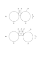
- 1A to 1C are diagrams illustrating examples of a form in which small particles are held by large particles that constitute a first surface.
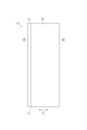
- FIG. 2 is a diagram showing a schematic layer structure of the sample support of FIG. 1;
- 2 is a SEM image showing a cross section of the sample support of FIG. 1;
- FIG. 6 is an enlarged view of a portion including an area A1 in FIG. 5 .
- FIG. 2 is a diagram showing a second step in a mass spectrometry method using the sample support of FIG. 1.
- FIG. 2 is a diagram showing an example of the configuration of a mass spectrometer for carrying out the above-described mass spectrometry method.
- FIG. 2 is a diagram showing an example of an irradiation area of microdroplets in an example and a comparative example.
- FIG. 13 is a diagram showing measurement results of detection sensitivity per irradiation region in an example and a comparative example.
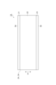
- FIG. 13 is a diagram showing a schematic layer structure of a sample support according to a first modified example.
- FIG. 13 is a diagram showing a schematic layer structure of a sample support according to a second modified example.
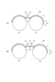
- FIG. 13 is a diagram showing a schematic configuration example of large particles, small particles, and a conductive layer on a first surface of a sample support according to a second modified example.
- the sample support 1 includes a substrate 2.
- the substrate 2 is formed in a rectangular plate shape.
- the substrate 2 has a first surface 2a and a second surface 2b opposite to the first surface 2a.
- the first surface 2a is insulating (electrically insulating).
- the substrate 2 is an insulating member. Therefore, not only the first surface 2a but the entire substrate 2 is insulating.
- the thickness of the substrate 2 (the distance from the first surface 2a to the second surface 2b) is, for example, about 100 ⁇ m to 1500 ⁇ m.
- the substrate 2 has an irregular porous structure 3 that opens to the first surface 2a.
- the entire substrate 2 is formed by the porous structure 3.
- the "irregular porous structure” refers to a structure in which voids (pores) extend in irregular directions and are irregularly distributed in three dimensions.
- the irregular porous structure includes a structure in which the pores enter the substrate 2 from one inlet (opening) on the first surface 2a side and branch into multiple paths, or a structure in which the pores enter the substrate 2 from multiple inlets (openings) on the first surface 2a side and merge into one path.
- a structure in which multiple pores extending from the first surface 2a to the second surface 2b along the thickness direction of the substrate 2 i.e., the direction D1 (first direction) in which the first surface 2a and the second surface 2b face each other
- the main pores i.e., a regular structure composed of pores extending mainly in one direction
- the porous structure 3 is formed by an aggregate of a plurality of particles.
- An aggregate of a plurality of particles is a structure in which a plurality of particles are gathered so as to be in contact with each other.
- An example of an aggregate of a plurality of particles is a structure in which a plurality of particles are bonded or adhered to each other. That is, in order to form a structure in which a plurality of particles are fixed in a state in which they are in contact with each other, the plurality of particles may be directly connected by fusion or the like, or may be indirectly connected via another member. In this embodiment, the plurality of particles are bonded to each other by fusion.
- the porous structure 3 is formed by a plurality of large particles 31 (first particles) connected to each other and a plurality of small particles 32 (second particles) having a diameter smaller than that of the large particles.
- the small particles 32 are formed of the same material as the large particles 31.
- the large particles 31 and the small particles 32 are formed of an insulating material.
- the large particles 31 and the small particles 32 are formed of glass.
- soda glass which has a relatively low melting point among glasses, is used as the material for the large particles 31 and the small particles 32 from the viewpoint of facilitating the manufacture of the aggregate structure.
- the large particles 31 and the small particles 32 are both spherical beads (glass beads).
- each of the multiple particles constituting the porous structure 3 can be visually classified into either large particles 31 or small particles 32. That is, the porous structure 3 is composed of particle groups that can be clearly distinguished into two groups in terms of "size". More specifically, each of the multiple large particles 31 has some variation in shape and size, but has a diameter larger than the small particles 32 at least to the extent that it can be distinguished from the SEM image, and is distinguishable from the small particles 32. Similarly, each of the multiple small particles 32 has some variation in shape and size, but has a diameter smaller than the large particles 31 at least to the extent that it can be distinguished from the SEM image, and is distinguishable from the large particles 31.
- the average particle size of the large particles 31 contained in a unit area of a predetermined size is R1
- the average particle size of the small particles 32 contained in the unit area is R2
- the following formula (1) is satisfied. More preferably, the following formula (2) is satisfied.
- the average particle sizes R1 and R2 can be calculated based on, for example, an SEM image as shown in FIG. 2.
- all spherical objects are extracted by performing known image processing (edge detection, etc.) on the SEM image in FIG. 2.
- the objects may be extracted by visual inspection instead of the image processing.
- an object having a maximum diameter is extracted from the extracted objects, and an object having a diameter with an error from the maximum diameter of a certain amount or less (for example, 30% or less of the maximum diameter) is classified as a large particle 31.
- the remaining objects that are not classified as large particles 31 are classified as small particles 32.
- the average diameter of the objects classified as large particles 31 is calculated as the average particle size R1 of the large particles 31, and the average diameter of the objects classified as small particles 32 is calculated as the average particle size R2 of the small particles 32.
- the average particle sizes R1 and R2 can be calculated by the above processing. Note that the above calculation method is an example, and the average particle sizes R1 and R2 may be calculated by other methods. As an example, the average particle size R1 of the large particles 31 is approximately 50 ⁇ m, and the average particle size R2 of the small particles 32 is approximately 5 ⁇ m to 20 ⁇ m.
- the first surface 2a of the substrate 2 is composed of the surfaces (upper surfaces) of the large particles 31 and the small particles 32 located on the uppermost surface (outermost layer) when the direction from the second surface 2b toward the first surface 2a is taken as the upward direction.
- the black parts are parts where the large particles 31 and the small particles 32 constituting the first surface 2a are not present, and correspond to the gaps (openings) between the particles.
- the first surface 2a When the first surface 2a is viewed along the direction D1 from a position facing the first surface 2a, it is preferable that in a unit area of a predetermined size (for example, an area of several hundred ⁇ m to 1 mm square), the area occupied by the large particles 31 is the largest, and the area occupied by the small particles 32 is next larger than the area occupied by the gaps (openings) between the particles.
- the porous structure 3 opens to the first surface 2a at such openings.
- the liquid that has permeated into the porous structure 3 from the openings on the first surface 2a can pass through the inside of the porous structure 3 and escape to the outside of the second surface 2b from the openings on the second surface 2b side.
- the porous structure 3 is open on both the first surface 2a and the second surface 2b, and the openings on the first surface 2a and the openings on the second surface 2b are connected to each other via the gaps between the particles inside the porous structure 3.
- the small particles 32 contained in the porous structure 3 are sandwiched and held between two or more large particles 31 (i.e., the large particles 31 located on the uppermost surface) that constitute the first surface 2a.
- the form in which the small particles 32 are held by the two or more large particles 31 that constitute the first surface 2a include a form in which one small particle 32 is held between two large particles 31 as shown in FIG. 3A, and a form in which multiple (two in this example) small particles 32 that are in contact with each other are held between two large particles 31 as shown in FIG. 3B.
- the form in which the small particles 32 are held by the two or more large particles 31 that constitute the first surface 2a is not limited to the above example.
- the porous structure 3 has a configuration in which one or more small particles 32 are held by two or more large particles 31 that make up the first surface 2a, and therefore has joints J1 between the large particles 31, joints J2 between the large particles 31 and the small particles 32, and joints J3 between the small particles 32 on the first surface 2a.
- the substrate 2 has a mixed layer 21 (first layer) and a large particle layer 22 (second layer).
- the mixed layer 21 includes the first surface 2a, and is a layer in which a plurality of large particles 31 and a plurality of small particles 32 are mixed.
- the large particle layer 22 is located closer to the second surface 2b than the mixed layer 21, and is a layer made of a plurality of large particles 31 and does not contain small particles 32.
- FIG. 5 is an SEM image of a cross section of a portion including the mixed layer 21 of the substrate 2 and a portion of the large particle layer 22 (a portion adjacent to the mixed layer 21).
- FIG. 6 is an enlarged view of a portion including the region A1 shown in FIG. 5. In FIG. 6, only some of the small particles 32 confirmed in the cross section of the region A1 are labeled.
- the large particles 31 located in the outermost layer i.e., the large particles 31 constituting the first surface 2a
- the portion from the first surface 2a to the second and third layers constitute the mixed layer 21. That is, in this example, the mixed layer 21 is constituted by the portion above the line L1 shown in FIG.
- the large particle layer 22 is constituted by the portion below the line L1 (the second surface 2b side).
- substantially only the multiple large particles 31 are in contact with the imaginary plane that constitutes the outermost surface of the first surface 2a (i.e., the plane along the upper line of region A1).
- the small particles 32 are sandwiched between the large particles 31 and are of a size and amount that does not contact the imaginary plane.
- the thickness of the mixed layer 21 in the direction D1 is 1/5 or less of the thickness of the large particle layer 22 in the direction D1.
- the mixed layer 21 is about 1/10 of the total thickness of the substrate 2 (porous structure 3).
- the thickness of the mixed layer 21 is about 1/9 of the thickness of the large particle layer 22.
- the sample support 1 (porous structure 3) is manufactured, for example, as follows. First, a sintered body is obtained by sintering a plurality of large particles 31 (first sintering step). Specifically, the plurality of large particles 31 are compressed by a press or the like and heated at a high temperature below the melting point of the large particles 31, so that the surfaces of the plurality of large particles 31 are fused and bonded to each other, and a sintered body consisting of only the plurality of large particles 31 is obtained. The sintered body has approximately the same external shape as the substrate 2 to be finally obtained.
- a plurality of small particles 32 are added to the surface of the sintered body corresponding to the first surface 2a (i.e., the surface that is to eventually become the first surface 2a) (addition step).
- a plurality of small particles 32 are sprinkled on the surface of the sintered body.
- the sintered body and the plurality of small particles 32 added to the sintered body are sintered (resintered) in a mixed state, and a porous structure 3 in which the surfaces of the plurality of large particles 31 and the plurality of small particles 32 are fused and bonded to each other is obtained (second sintering step).
- the method of manufacturing the sample support 1 is not limited to the above method.
- the sample support 1 (porous structure 3) may be manufactured by a single sintering process in a state where a plurality of large particles 31 and a plurality of small particles 32 are mixed.
- the plurality of large particles 31 are not fixed (sintered)
- a large number of the plurality of small particles 32 may also be contained inside the sintered body (i.e., inside the substrate 2), and the above-mentioned large particle layer 22 may not be formed properly.
- sample support 1 (porous structure 3) by a two-stage sintering process as described above.
- the sample support 1 manufactured by the above-mentioned manufacturing method can also be considered to have a structure in which a plurality of small particles 32 are added as a separate member from the substrate to the first surface of the substrate as a sintered body formed by the plurality of large particles 31 so as to be able to maintain a certain outer shape.
- the multiple large particles 31 can be considered as elements that make up the substrate 2 of the sample support 1, and the multiple small particles 32 can be considered as elements that are added (filled) to a portion of the substrate 2, including the first surface 2a, in order to increase the surface area and seams (seams J2, J3) of the first surface 2a of such substrate 2 (multiple large particles 31).
- sample support 1 is prepared as a sample support for ionizing a sample (first step).
- the sample support 1 may be prepared by being manufactured by the practitioner of the ionization method and mass spectrometry method, or may be prepared by being transferred from the manufacturer or seller of the sample support 1.
- the sample Sa is transferred to the first surface 2a of the substrate 2 (second step).
- the sample Sa is a slice of fruit (lemon).
- the sample Sa is pressed against the first surface 2a of the substrate 2, so that a portion of the sample Sa is adhered onto the first surface 2a.
- the slide glass 6 and the sample support 1 are placed on the stage 41 in the ionization chamber 40 of the mass spectrometer 10. Then, the component Sa1 on the first surface 2a of the substrate 2 is irradiated with the charged microdroplets I to an area (hereinafter referred to as the "target area") including the area where the transferred sample Sa exists, and the ionized component, sample ion Sa2, is attracted (third step).
- the stage 41 is moved in the X-axis direction and the Y-axis direction to move the irradiation area I1 of the charged microdroplets I relative to the target area (i.e., the charged microdroplets I are scanned relative to the target area).
- the above first, second, and third steps correspond to the ionization method using the sample support 1 (in this embodiment, desorption electrospray ionization method).
- charged microdroplets I are sprayed from the nozzle 42, and sample ions Sa2 are sucked in from the suction port of the ion transport tube 43.
- the nozzle 42 has a double-cylinder structure.
- the solvent is guided into the inner cylinder of the nozzle 42 with a high voltage applied. This gives a one-sided charge to the solvent that has reached the tip of the nozzle 42.
- a nebulizing gas is guided into the outer cylinder of the nozzle 42. This causes the solvent to be sprayed as microdroplets, and the solvent ions generated in the process of evaporating the solvent are emitted as charged microdroplets I.
- the sample ions Sa2 sucked in from the suction port of the ion transport tube 43 are transported into the mass spectrometry chamber 50 by the ion transport tube 43.
- the mass spectrometry chamber 50 is under high vacuum conditions (vacuum level of 10 ⁇ 4 Torr or less).
- the sample ions Sa2 are focused by the ion optical system 51 and introduced into the quadrupole mass filter 52 to which a radio frequency voltage is applied.
- ions having a mass number determined by the frequency of the radio frequency voltage are selectively passed, and the passed ions are detected by the detector 53 (fourth step).
- the mass number of the ions reaching the detector 53 is sequentially changed to obtain a mass spectrum in a predetermined mass range.
- the detector 53 detects ions corresponding to the position of the irradiation region I1 of the charged microdroplet I, and an image of the two-dimensional distribution of the molecules constituting the sample Sa is obtained.
- the above first, second, third and fourth steps correspond to a mass spectrometry method using the sample support 1.
- the porous structure 3 is configured to include not only a plurality of large particles 31 but also small particles 32 sandwiched and held between two or more large particles 31 constituting the first surface 2a. This makes it possible to reduce the gaps of the sample support 1 at the first surface 2a (i.e., spaces where no particles constituting the porous structure 3 exist) when the sample support 1 is viewed from a direction facing the first surface 2a. That is, as can be seen from the SEM image of FIG. 2, the gaps between the large particles 31 at the outermost layer are filled by the plurality of small particles 32 being held between the plurality of large particles 31 at the outermost layer. Also, as shown in FIG.
- the sample Sa transferred or dropped on the first surface 2a is particularly likely to remain at such joints J1, J2, and J3. That is, by increasing the number of such joints J1, J2, and J3, the sample Sa to be measured can be suitably retained on the first surface 2a (particularly on the joints J1, J2, and J3 described above).
- the sample support 1 it is possible to efficiently ionize the component Sa1 of the sample Sa retained on the first surface 2a, and therefore the detection sensitivity of the component Sa1 of the sample Sa (i.e., the detection sensitivity of the sample ion Sa2) in mass spectrometry using the sample support 1 (for example, the first to fourth steps in the above embodiment) can be effectively improved. Furthermore, since the sample Sa is more likely to remain on the first surface 2a as described above, the area on the first surface 2a where the sample Sa is stained becomes larger and the stain becomes darker. This improves the visibility of the sample Sa attached to the measurement surface (first surface 2a) of the sample support 1, and also provides the effect of facilitating the work of determining the irradiation range of the microdroplets I for ionization.
- FIG. 10 shows mass spectra obtained by performing mass analysis (laser desorption ionization method) of sample Sa (Angiotensin II, as an example) using each of the above examples and comparative examples. That is, in FIG. 10, the horizontal axis indicates the mass-to-charge ratio (m/z), and the vertical axis indicates the signal intensity (arbitrary unit: arb.unit).
- FIG. 10 shows mass spectrum M1 of the embodiment and mass spectrum M2 of the comparative example.
- mass spectrum M1 of the embodiment In order to easily compare mass spectrum M1 of the embodiment and mass spectrum M2 of the comparative example, the origin of the signal intensity of mass spectrum M1 of the embodiment (i.e., the value corresponding to the signal intensity "0") is shifted upward (by about +0.8).
- mass spectra M1 and M2 are normalized by setting the peak intensity of sodium citrate in each of the embodiment and the comparative example as 100% (1.0). As shown in FIG. 10, according to the embodiment, a higher signal intensity was obtained at the position corresponding to sample Sa (Angiotensin II) than in the comparative example.
- FIG. 10 shows the measurement results when the laser desorption ionization method is performed using a sample support having a conductive layer 4, but it is believed that similar results will be obtained when the mass analysis by the desorption electrospray ionization method described above (the first to fourth steps described above) is performed using a sample support not having a conductive layer 4.
- the component Sa1 of the sample Sa is more likely to remain on the first surface 2a in the example (sample support 1) than in the comparative example (i.e., a sample support having a substrate (porous structure) composed only of a plurality of large particles 31 and not including a plurality of small particles 32), and therefore it is believed that high detection sensitivity can be obtained in the mass analysis by the desorption electrospray ionization method described above (the first to fourth steps described above).
- the small particles 32 are formed of the same material as the large particles 31. If the large particles 31 and the small particles 32 were formed of different materials, there is a risk that a signal caused by a material (the material of the small particles 32) different from the base material (the material of the large particles 31) may be generated as noise during ionization (in this embodiment, during ionization of the component Sa1 by irradiation with the microdroplets I). In contrast, by forming the large particles 31 and the small particles 32 from the same material as in this embodiment, the occurrence of the above-mentioned problems can be avoided.
- the second sintering step described above can be easily performed (i.e., it can be performed under the same temperature conditions as the first sintering step), and the substrate 2 (porous structure 3) can be manufactured easily and with stable quality.
- the large particles 31 and the small particles 32 are formed of an insulating material.
- the substrate 2 in which a plurality of large particles 31 and a plurality of small particles 32 are integrated can be manufactured by a simple method such as sintering.
- the sample support 1 suitable for the above-mentioned desorption electrospray ionization method can be realized.
- the large particles 31 and the small particles 32 are formed of glass.
- the heating temperature required for the above-mentioned first sintering step and second sintering step can be made relatively low, so that the substrate 2 having the porous structure 3 can be obtained suitably and inexpensively.
- the sizes of the multiple large particles 31 and multiple small particles 32 contained in the porous structure 3 are adjusted so as to satisfy the above formula (1) (i.e., "R1 x 1/100 ⁇ R2 ⁇ R1 x 1/2").
- R1 x 1/100 ⁇ R2 ⁇ R1 x 1/4 the sizes of the multiple large particles 31 and multiple small particles 32 contained in the porous structure 3 are adjusted so as to satisfy the above formula (1) (i.e., "R1 x 1/100 ⁇ R2 ⁇ R1 x 1/2").
- the substrate 2 has a mixed layer 21 including the first surface 2a, and a large particle layer 22 located on the second surface 2b side of the mixed layer 21. That is, in the sample support 1, the mixed layer 21 is provided with a mixture of large particles 31 and small particles 32 to make it easier to retain the sample Sa on the first surface 2a, while the large particle layer 22 is provided below the mixed layer 21 (on the second surface 2b side) and does not contain small particles 32, so that the liquid passes through it more easily than the mixed layer 21. This allows the liquid component to escape appropriately from the mixed layer 21 to the large particle layer 22 when the sample Sa to be measured, which contains a liquid component, is transferred or dropped onto the first surface 2a of the sample support 1.
- the thickness of the mixed layer 21 in the direction D1 is 1/5 or less of the thickness of the large particle layer 22 in the direction D1.
- the manufacturing method of the sample support 1 also includes the above-mentioned first sintering step, the addition step, and the second sintering step.
- a highly reliable porous structure 3 can be obtained by performing a two-stage sintering step. That is, first, in the first sintering step, a structure having high strength and stability is obtained only from a plurality of large particles 31 (i.e., the part that constitutes the framework of the porous structure 3), and then, by going through the addition step and the second sintering step, a sample support 1 that exhibits the above-mentioned effects can be easily and stably obtained.
- the irradiation area I1 of the charged microdroplets I is moved relative to the first surface 2a.
- the position information of the sample Sa two-dimensional distribution information of the molecules (component Sa1) that constitute the sample Sa) is maintained. Therefore, by moving the irradiation area I1 of the charged microdroplets I relative to the first surface 2a (target area), the component Sa1 of the sample Sa can be ionized while maintaining the position information of the sample Sa.
- the two-dimensional distribution of the molecules that constitute the sample Sa can be imaged.
- the nozzle 42 can be brought closer to the first surface 2a as described above, the irradiation area I1 of the charged microdroplets I can be suppressed from expanding. As a result, in the later step of detecting the sample ions Sa2, the two-dimensional distribution of the molecules that constitute the sample Sa can be imaged with high resolution.
- the component Sa1 of the sample Sa is suitably ionized by irradiation with the charged microdroplets I, so that the signal strength can be improved when detecting the sample ions Sa2.
- the present disclosure is not limited to the above-described embodiment.
- the material and shape of each component are not limited to the above-described material and shape, and various materials and shapes can be adopted.
- some components included in the sample support 1 according to the above embodiment may be omitted or modified as appropriate.
- some characteristic components included in the sample support 1 and some effects exerted by each component have been described, but the sample support according to the present disclosure does not necessarily need to be configured to exert all the effects described in the above embodiment, and may be configured to exert only some of the effects described in the above embodiment.
- the sample support only needs to have a configuration essential for exerting at least the part of the effect, and the configuration that is not essential for exerting the part of the effect may be omitted or modified as appropriate. Note that, when focusing on one effect, the configuration essential for exerting the one effect should be reasonably understood based on technical common sense and the description of this specification, with the person skilled in the art as the standard. Below, some specific modified examples of the sample support of the present disclosure are illustrated.
- a sample support 1A according to a first modified example will be described with reference to Fig. 11.
- the sample support 1A differs from the sample support 1 in that it has a symmetrical structure in the direction D1, i.e., the portion on the first surface 2a side and the portion on the second surface 2b side have the same structure, and both the first surface 2a and the second surface 2b are configured to be usable as measurement surfaces (surfaces onto which the sample Sa is transferred or dropped).
- the substrate 2A (porous structure 3A) of the sample support 1A includes a second surface 2b and is provided with a mixed layer 23 (third layer) in which a plurality of large particles 31 and a plurality of small particles 32 are mixed, and the large particle layer 22 is located between the mixed layer 21 and the mixed layer 23.
- the second surface 2b is also configured in the same manner as the first surface 2a. In other words, at least a portion of the plurality of small particles 32 contained in the mixed layer 23 is sandwiched and held between two or more large particles 31 that constitute the second surface 2b.
- sample support 1B according to the second modification will be described with reference to Figures 12 and 13.
- the sample support 1B differs from the sample support 1 in that it includes a conductive layer 4.
- the sample support 1B can be used in an ionization method (such as laser desorption ionization) that requires application of a voltage on the first surface 2a to detect a component Sa1 of an ionized sample Sa.
- the conductive layer 4 covers the first surface 2a so as not to block the openings of the porous structure 3 on the first surface 2a. That is, the conductive layer 4 is provided so as not to completely block the openings (gaps between particles) of the porous structure 3 on the first surface 2a.
- the liquid components contained in the sample Sa transferred or dropped onto the first surface 2a can penetrate into the porous structure 3 and escape to the large particle layer 22.
- the conductive layer 4 is also formed on the surface of the small particles 32, so that a more continuous conductive layer 4 can be formed and the conductivity on the first surface 2a can be suitably secured.
- the conductive layer 4 is in a state in which gaps are provided to the extent that at least the liquid components contained in the sample Sa can escape to the large particle layer 22.
- the conductive layer 4 covers the first surface 2a along the uneven shape of the first surface 2a formed by the large particles 31 and the small particles 32 (for example, the recessed shapes at the joints J1, J2, J3, etc.). That is, the thickness of the conductive layer 4 is made very thin compared to the size (diameter) of the large particles 31 and the small particles 32. As a result, the shape of the outer surface of the conductive layer 4 formed on the surfaces of the large particles 31 and the small particles 32 follows the original surface shapes of the large particles 31 and the small particles 32. Therefore, as shown in FIG. 13, the uneven shape of the first surface 2a (particularly the recessed shapes at the joints J1, J2, J3) is maintained even after the conductive layer 4 is formed.
- the conductive layer 4 is formed of a conductive material. It is preferable that the material of the conductive layer 4 is a metal that has low affinity (reactivity) with the sample Sa and high conductivity. From this perspective, it is preferable that the material of the conductive layer 4 is, for example, Au (gold), Pt (platinum), etc.
- the conductive layer 4 is formed to a thickness of about 1 nm to 350 nm by, for example, a plating method, an atomic layer deposition method (ALD: atomic layer deposition), a vapor deposition method, a sputtering method, etc. Note that, for example, Cr (chromium), Ni (nickel), Ti (titanium), etc. may be used as the material of the conductive layer 4.
- the conductive layer 4 is formed by performing the above-mentioned deposition method, sputtering method, etc. from the first surface 2a side so as to cover the surfaces of the large particles 31 and small particles 32 constituting the first surface 2a that are exposed to the first surface 2a.
- the conductive layer 4 is formed by ALD, the conductive layer 4 can be formed not only on the surfaces exposed to the first surface 2a side but also on the surfaces of the large particles 31 and small particles 32 facing the second surface 2b side by penetrating into the gaps of the porous structure 3.
- the conductive layer 4 is formed so as to cover at least the surfaces exposed to the first surface 2a side of the large particles 31 and small particles 32 constituting the first surface 2a, and may be provided so as to cover the entire surfaces of the large particles 31 and small particles 32 constituting the first surface 2a.
- the sample support 1B makes it possible to obtain the same effect as the sample support 1 (i.e., without impeding the effect of the sample support 1 due to the presence of the conductive layer 4), while allowing the sample support 1B to be used in laser desorption ionization and the like. More specifically, when using laser desorption ionization and the like, that is, when it is necessary to apply a voltage to the first surface 2a in order to guide the component Sa1 of the sample Sa ionized on the first surface 2a to the ion detector (ground electrode side), it becomes possible to apply an appropriate voltage via the conductive layer 4.
- the configurations of the above-described embodiment, the first modification, and the second modification may be appropriately combined.
- the first modification and the second modification may be combined.
- the conductive layer 4 is provided on each of the first surface 2a and the second surface 2b of the sample support 1A.
- the porous structure 3 is configured such that the multiple large particles 31 and multiple small particles 32 are fused to each other, so that the small particles 32 are sandwiched and held between two or more large particles 31 that make up the first surface 2a, but the small particles 32 do not necessarily have to be fused to adjacent large particles 31.
- the sample support 1 is configured to include only the substrate 2, but the sample support 1 may include a member other than the substrate 2.
- a support member such as a frame
- a support member for supporting the substrate 2 may be provided on a part of the substrate 2 (such as a corner).
- sample Sa is not limited to the slice of fruit (lemon) exemplified in the above embodiment.
- the sample Sa may have a flat surface or an uneven surface.
- the sample Sa may also be something other than fruit, such as a plant leaf. In this case, by transferring the components of the surface of the leaf, which is the sample Sa, to the first surface 2a, it is possible to perform imaging mass analysis of the surface (veins) of the leaf.
- the entire substrate 2 is constituted by the porous structure 3, but the porous structure 3 may be formed in a part of the substrate 2.
- the porous structure 3 may be formed only in a central region (a part of the first surface 2a) of the substrate 2 that is determined as a measurement region for transferring or dropping the sample Sa.
- the porous structure 3 may not be formed in other parts of the substrate 2.
- the porous structure 3 may not be formed over the entire area from the first surface 2a to the second surface 2b. In other words, the porous structure 3 only needs to be open at least to the first surface 2a, and may not be open to the second surface 2b.
- the substrate 2 may be constituted by a flat plate including the second surface 2b and a porous structure 3 provided on the surface of the plate opposite to the second surface 2b.
- the substrate 2 may be constituted by a glass plate and a sintered body (porous structure 3) of glass beads provided on the glass plate.
- the first surface 2a is insulating so that the sample support 1 can be used in desorption electrospray ionization.
- the substrate 2 (porous structure 3) itself is made of an insulating material, so that the first surface 2a is insulating.
- the sample support 1 can be configured to be used in desorption electrospray ionization by a configuration other than the above.
- the substrate 2 (porous structure 3) may be made of a conductive material.
- an insulating coating may be applied to the first surface 2a of the substrate 2, so that the first surface 2a is insulating.
- the first surface 2a of the substrate 2 can be made insulating, so that the substrate 2 formed of a conductive material can be used.
- the porous structure 3 may be formed of an aggregate of multiple particles (large particles 31 and small particles 32) made of metal. In this way, when an insulating coating is provided, the freedom of selection of the substrate material (i.e., the material of the large particles 31 and the small particles 32) can be improved.
- the material of the large particles 31 and small particles 32 constituting the porous structure 3 may be a metal oxide (e.g., alumina, etc.) or an insulating coated metal, in addition to the insulating material exemplified in the above embodiment (glass (soda glass) is used as an example in the above embodiment).
- the shape of the large particles 31 and small particles 32 constituting the porous structure 3 is not limited to a spherical shape, and may have a shape other than a spherical shape.
- 1, 1A, 1B... sample support 2, 2A... substrate, 2a... first surface, 2b... second surface, 3, 3A... porous structure, 4... conductive layer, 21... mixed layer (first layer), 22... large particle layer (second layer), 23... mixed layer (third layer), 31... large particles (first particles), 32, 32A... small particles (second particles), J1, J2, J3... joints, Sa... sample, Sa1... component, Sa2... sample ions (ionized components).
Landscapes
- Chemical & Material Sciences (AREA)
- Analytical Chemistry (AREA)
- Physics & Mathematics (AREA)
- Electrochemistry (AREA)
- Health & Medical Sciences (AREA)
- Life Sciences & Earth Sciences (AREA)
- Chemical Kinetics & Catalysis (AREA)
- Biochemistry (AREA)
- General Health & Medical Sciences (AREA)
- General Physics & Mathematics (AREA)
- Immunology (AREA)
- Pathology (AREA)
- Other Investigation Or Analysis Of Materials By Electrical Means (AREA)
Abstract
Description
第1表面と、前記第1表面とは反対側の第2表面と、少なくとも前記第1表面に開口する不規則な多孔質構造と、を有する基板を備え、
前記多孔質構造は、互いに連結された複数の第1粒子と、前記第1粒子よりも小さい径を有する複数の第2粒子と、によって形成されており、
前記複数の第2粒子の少なくとも一部は、前記第1表面を構成する2以上の前記第1粒子の間に挟まれて保持されている、試料支持体。
R1×1/100≦R2≦R1×1/2 ・・・(1)
前記第1表面を含み、複数の前記第1粒子及び複数の前記第2粒子が混在する第1層と、
前記第1層よりも前記第2表面側に位置し、複数の前記第1粒子からなり、前記第2粒子を含まない第2層と、を有する、[1]~[5]のいずれかの試料支持体。
前記第2層は、前記第1層と前記第3層との間に位置しており、
前記第3層に含まれる複数の前記第2粒子の少なくとも一部は、前記第2表面を構成する2以上の前記第1粒子の間に挟まれて保持されている、[6]又は[7]の試料支持体。
前記複数の第1粒子を焼結することにより、前記基板と略同一の外形を有する焼結体を得る第1焼結工程と、
前記焼結体における前記第1表面に対応する面に、前記複数の第2粒子を添加する添加工程と、
前記添加工程により得られた前記焼結体及び前記複数の第2粒子を焼結することにより、前記多孔質構造を得る第2焼結工程と、を含む、試料支持体の製造方法。
図1に示されるように、試料支持体1は、基板2を備えている。一例として、基板2は、矩形板状に形成されている。基板2は、第1表面2aと、第1表面2aとは反対側の第2表面2bと、を有している。第1表面2aは、絶縁性(電気絶縁性)を有している。本実施形態では、基板2は、絶縁性の部材である。このため、第1表面2aだけでなく、基板2の全体が絶縁性を有している。基板2の厚さ(第1表面2aから第2表面2bまでの距離)は、例えば100μm~1500μm程度である。
R1×1/100≦R2≦R1×1/2 ・・・(1)
R1×1/10≦R2≦R1×2/5 ・・・(2)
試料支持体1(多孔質構造3)は、例えば、以下のようにして製造される。まず、複数の大粒子31が焼結されることにより、焼結体が得られる(第1焼結工程)。具体的には、複数の大粒子31がプレス機等によって押し固められた状態で、大粒子31の融点以下の高温下で加熱されることにより、複数の大粒子31同士の表面が融着されることによって結合し、複数の大粒子31のみからなる焼結体が得られる。上記焼結体は、最終的に得られる基板2と略同一の外形を有している。続いて、上記焼結体における第1表面2aに対応する面(すなわち、最終的に第1表面2aになる予定の面)に、複数の小粒子32が添加される(添加工程)。例えば、複数の小粒子32が、上記焼結体の上記面に対してまぶされる。続いて、上記焼結体及び上記焼結体に添加された複数の小粒子32が混在する状態で焼結(再焼結)されることにより、複数の大粒子31及び複数の小粒子32の表面が融着されることによって結合された多孔質構造3が得られる(第2焼結工程)。
試料支持体1を用いたイオン化法及び質量分析方法について説明する。まず、試料のイオン化用の試料支持体として、上述した試料支持体1を用意する(第1工程)。試料支持体1は、イオン化法及び質量分析方法の実施者によって製造されることにより用意されてもよいし、試料支持体1の製造者又は販売者等から譲渡されることにより用意されてもよい。
上述した試料支持体1では、多孔質構造3が、複数の大粒子31だけでなく、第1表面2aを構成する2以上の大粒子31の間に挟まれて保持された小粒子32を含んで構成される。これにより、試料支持体1を第1表面2aに対向する方向から見た場合に、第1表面2aにおける試料支持体1の隙間(すなわち、多孔質構造3を構成する粒子が存在しない空間)を減らすことができる。すなわち、図2のSEM像からわかるように、複数の小粒子32が最表層の複数の大粒子31の間に保持されることにより、最表層の大粒子31間の隙間が埋められている。また、図2に示されるように、第1表面2aにおいて、大粒子31同士の繋ぎ目J1だけでなく、大粒子31と小粒子32との繋ぎ目J2、及び小粒子32同士の繋ぎ目J3が加わることになる。第1表面2aに転写又は滴下された試料Saは、このような繋ぎ目J1,J2,J3に特に留まり易い。すなわち、このような繋ぎ目J1,J2,J3を増やすことにより、測定対象の試料Saを第1表面2a上(特に上述した繋ぎ目J1,J2,J3の上)に好適に留めることができる。従って、試料支持体1によれば、第1表面2a上に留まった試料Saの成分Sa1を効率的にイオン化することが可能となるため、試料支持体1を用いた質量分析(例えば、上記実施形態における第1~第4工程)における試料Saの成分Sa1の検出感度(すなわち、試料イオンSa2の検出感度)を効果的に向上させることができる。さらに、上記のように第1表面2a上に試料Saが留まり易くなることにより、第1表面2aにおける試料Saの染みがつく領域が大きくなると共に染みが濃くなる。これにより、試料支持体1の測定面(第1表面2a)に付着した試料Saの視認性が向上し、イオン化のための微小液滴Iの照射範囲を決定する作業等を容易化できるという効果も得られる。
本開示は、上述した実施形態に限定されない。各構成の材料及び形状には、上述した材料及び形状に限らず、様々な材料及び形状を採用することができる。また、上記実施形態に係る試料支持体1に含まれる一部の構成は、適宜省略又は変更されてもよい。例えば、上記実施形態では、試料支持体1に含まれるいくつかの特徴的な構成、及び各構成によって発揮されるいくつかの効果について説明したが、本開示に係る試料支持体は、必ずしも、上記実施形態で説明された全ての効果を発揮するように構成される必要はなく、上記実施形態で説明された一部の効果のみを発揮するように構成されてもよい。後者の場合には、試料支持体は、少なくとも当該一部の効果を発揮するために必須の構成を備えていればよく、当該一部の効果を発揮するために必須ではない構成は適宜省略又は変更されてもよい。なお、一の効果に着目した場合において、当該一の効果を発揮するために必須の構成は、当業者を基準として、技術常識及び本明細書の記載に基づいて、合理的に把握されるべきである。以下、本開示の試料支持体について、いくつかの具体的な変形例を例示する。
図11を参照して、第1変形例に係る試料支持体1Aについて説明する。試料支持体1Aは、方向D1において対称的な構造を有する点、すなわち、第1表面2a側の部分と第2表面2b側の部分とが同様の構成を有しており、第1表面2a及び第2表面2bの両方を測定面(試料Saが転写又は滴下される面)として利用可能に構成されている点において、試料支持体1と相違している。
図12及び図13を参照して、第2変形例に係る試料支持体1Bについて説明する。試料支持体1Bは、導電層4を備える点において、試料支持体1と相違している。試料支持体1Bは、導電層4を備えることにより、イオン化された試料Saの成分Sa1を検出するために第1表面2a上に電圧を印加する必要があるイオン化法(例えば、レーザ脱離イオン化法等)に用いることが可能とされている。
上述した実施形態、第1変形例、及び第2変形例の構成は適宜組み合わせられてもよい。例えば、第1変形例と第2変形例とを組み合わせてもよい。この場合、試料支持体1Aの第1表面2a及び第2表面2bの各々に、導電層4が設けられる。
Claims (10)
- 試料のイオン化用の試料支持体であって、
第1表面と、前記第1表面とは反対側の第2表面と、少なくとも前記第1表面に開口する不規則な多孔質構造と、を有する基板を備え、
前記多孔質構造は、互いに連結された複数の第1粒子と、前記第1粒子よりも小さい径を有する複数の第2粒子と、によって形成されており、
前記複数の第2粒子の少なくとも一部は、前記第1表面を構成する2以上の前記第1粒子の間に挟まれて保持されている、試料支持体。 - 前記第2粒子は、前記第1粒子と同一の材料によって形成されている、請求項1に記載の試料支持体。
- 前記第1粒子及び前記第2粒子は、絶縁性材料によって形成されている、請求項2に記載の試料支持体。
- 前記絶縁性材料は、ガラスである、請求項3に記載の試料支持体。
- 前記第1表面に対向する位置から前記第1表面と前記第2表面とが対向する方向に沿って前記第1表面を見た場合において、所定の大きさの単位領域に含まれる前記第1粒子の平均粒径をR1とし、前記単位領域に含まれる前記第2粒子の平均粒径をR2とした場合、下記式(1)が満たされる、請求項1に記載の試料支持体。
R1×1/100≦R2≦R1×1/2 ・・・(1) - 前記基板は、
前記第1表面を含み、複数の前記第1粒子及び複数の前記第2粒子が混在する第1層と、
前記第1層よりも前記第2表面側に位置し、複数の前記第1粒子からなり、前記第2粒子を含まない第2層と、を有する、請求項1に記載の試料支持体。 - 前記第1表面と前記第2表面とが対向する第1方向における前記第1層の厚さは、前記第1方向における前記第2層の厚さの1/5以下である、請求項6に記載の試料支持体。
- 前記基板は、前記第2表面を含み、複数の前記第1粒子及び複数の前記第2粒子が混在する第3層を更に備え、
前記第2層は、前記第1層と前記第3層との間に位置しており、
前記第3層に含まれる複数の前記第2粒子の少なくとも一部は、前記第2表面を構成する2以上の前記第1粒子の間に挟まれて保持されている、請求項6又は7に記載の試料支持体。 - 前記第1表面における前記多孔質構造の開口部を塞がず、且つ、前記第1粒子及び前記第2粒子によって構成された前記第1表面の凹凸形状に沿って前記第1表面を覆う導電層を更に備える、請求項1に記載の試料支持体。
- 請求項1に記載の試料支持体の製造方法であって、
前記複数の第1粒子を焼結することにより、前記基板と略同一の外形を有する焼結体を得る第1焼結工程と、
前記焼結体における前記第1表面に対応する面に、前記複数の第2粒子を添加する添加工程と、
前記添加工程により得られた前記焼結体及び前記複数の第2粒子を焼結することにより、前記多孔質構造を得る第2焼結工程と、を含む、試料支持体の製造方法。
Priority Applications (2)
| Application Number | Priority Date | Filing Date | Title |
|---|---|---|---|
| EP24818964.9A EP4685476A1 (en) | 2023-06-07 | 2024-02-02 | Sample support and method for manufacturing sample support |
| CN202480037429.XA CN121511403A (zh) | 2023-06-07 | 2024-02-02 | 试样支承体及试样支承体的制造方法 |
Applications Claiming Priority (2)
| Application Number | Priority Date | Filing Date | Title |
|---|---|---|---|
| JP2023-093792 | 2023-06-07 | ||
| JP2023093792A JP7492065B1 (ja) | 2023-06-07 | 2023-06-07 | 試料支持体及び試料支持体の製造方法 |
Publications (1)
| Publication Number | Publication Date |
|---|---|
| WO2024252725A1 true WO2024252725A1 (ja) | 2024-12-12 |
Family
ID=91194192
Family Applications (1)
| Application Number | Title | Priority Date | Filing Date |
|---|---|---|---|
| PCT/JP2024/003550 Ceased WO2024252725A1 (ja) | 2023-06-07 | 2024-02-02 | 試料支持体及び試料支持体の製造方法 |
Country Status (4)
| Country | Link |
|---|---|
| EP (1) | EP4685476A1 (ja) |
| JP (2) | JP7492065B1 (ja) |
| CN (1) | CN121511403A (ja) |
| WO (1) | WO2024252725A1 (ja) |
Citations (5)
| Publication number | Priority date | Publication date | Assignee | Title |
|---|---|---|---|---|
| JP2003510065A (ja) * | 1999-09-27 | 2003-03-18 | アレイ バイオサイエンス コーポレイション | 分析物検出のためのレセプターを有する粒子構造体 |
| US20210346963A1 (en) * | 2020-05-08 | 2021-11-11 | Grid Logic Incorporated | System and method for manufacturing a part |
| WO2022049846A1 (ja) * | 2020-09-04 | 2022-03-10 | 浜松ホトニクス株式会社 | 試料支持体、イオン化法、及び質量分析方法 |
| WO2023157353A1 (ja) * | 2022-02-16 | 2023-08-24 | 浜松ホトニクス株式会社 | 試料支持体、イオン化法、及び質量分析方法 |
| WO2023157352A1 (ja) * | 2022-02-16 | 2023-08-24 | 浜松ホトニクス株式会社 | 試料支持体、イオン化法、及び質量分析方法 |
-
2023
- 2023-06-07 JP JP2023093792A patent/JP7492065B1/ja active Active
-
2024
- 2024-02-02 CN CN202480037429.XA patent/CN121511403A/zh active Pending
- 2024-02-02 WO PCT/JP2024/003550 patent/WO2024252725A1/ja not_active Ceased
- 2024-02-02 EP EP24818964.9A patent/EP4685476A1/en active Pending
- 2024-05-16 JP JP2024080039A patent/JP2024177083A/ja active Pending
Patent Citations (6)
| Publication number | Priority date | Publication date | Assignee | Title |
|---|---|---|---|---|
| JP2003510065A (ja) * | 1999-09-27 | 2003-03-18 | アレイ バイオサイエンス コーポレイション | 分析物検出のためのレセプターを有する粒子構造体 |
| US20210346963A1 (en) * | 2020-05-08 | 2021-11-11 | Grid Logic Incorporated | System and method for manufacturing a part |
| WO2022049846A1 (ja) * | 2020-09-04 | 2022-03-10 | 浜松ホトニクス株式会社 | 試料支持体、イオン化法、及び質量分析方法 |
| JP2022043571A (ja) | 2020-09-04 | 2022-03-16 | 浜松ホトニクス株式会社 | 試料支持体、イオン化法、及び質量分析方法 |
| WO2023157353A1 (ja) * | 2022-02-16 | 2023-08-24 | 浜松ホトニクス株式会社 | 試料支持体、イオン化法、及び質量分析方法 |
| WO2023157352A1 (ja) * | 2022-02-16 | 2023-08-24 | 浜松ホトニクス株式会社 | 試料支持体、イオン化法、及び質量分析方法 |
Also Published As
| Publication number | Publication date |
|---|---|
| EP4685476A1 (en) | 2026-01-28 |
| JP2024175787A (ja) | 2024-12-19 |
| JP7492065B1 (ja) | 2024-05-28 |
| JP2024177083A (ja) | 2024-12-19 |
| CN121511403A (zh) | 2026-02-10 |
Similar Documents
| Publication | Publication Date | Title |
|---|---|---|
| JP7404195B2 (ja) | 試料支持体、イオン化法、及び質量分析方法 | |
| US11735406B2 (en) | Sample support | |
| JP7492065B1 (ja) | 試料支持体及び試料支持体の製造方法 | |
| WO2023157353A1 (ja) | 試料支持体、イオン化法、及び質量分析方法 | |
| JP7469540B1 (ja) | 試料支持体及び試料支持体の製造方法 | |
| JP7790999B2 (ja) | 試料支持体、イオン化法、及び質量分析方法 | |
| JP2020153821A (ja) | 試料支持体、試料支持体の製造方法、イオン化法及び質量分析方法 | |
| JP7786973B2 (ja) | 試料支持体、及び試料支持体の製造方法 | |
| JP7471174B2 (ja) | 試料支持体 | |
| JP7365024B2 (ja) | 試料支持体、イオン化方法及び質量分析方法 | |
| WO2021176856A1 (ja) | 試料支持体、イオン化方法及び質量分析方法 | |
| WO2021176857A1 (ja) | 試料支持体、イオン化方法及び質量分析方法 | |
| JP2020165808A (ja) | イオン化法及び質量分析方法 | |
| JPWO2019106962A1 (ja) | レーザ脱離イオン化法及び質量分析方法 |
Legal Events
| Date | Code | Title | Description |
|---|---|---|---|
| 121 | Ep: the epo has been informed by wipo that ep was designated in this application |
Ref document number: 24818964 Country of ref document: EP Kind code of ref document: A1 |
|
| WWE | Wipo information: entry into national phase |
Ref document number: 2024818964 Country of ref document: EP |
|
| ENP | Entry into the national phase |
Ref document number: 2024818964 Country of ref document: EP Effective date: 20251022 |
|
| ENP | Entry into the national phase |
Ref document number: 2024818964 Country of ref document: EP Effective date: 20251022 |
|
| ENP | Entry into the national phase |
Ref document number: 2024818964 Country of ref document: EP Effective date: 20251022 |
|
| ENP | Entry into the national phase |
Ref document number: 2024818964 Country of ref document: EP Effective date: 20251022 |
|
| ENP | Entry into the national phase |
Ref document number: 2024818964 Country of ref document: EP Effective date: 20251022 |
|
| ENP | Entry into the national phase |
Ref document number: 2024818964 Country of ref document: EP Effective date: 20251022 |
|
| NENP | Non-entry into the national phase |
Ref country code: DE |
|
| WWP | Wipo information: published in national office |
Ref document number: 2024818964 Country of ref document: EP |