WO2024252756A1 - 保護装置 - Google Patents
保護装置 Download PDFInfo
- Publication number
- WO2024252756A1 WO2024252756A1 PCT/JP2024/010767 JP2024010767W WO2024252756A1 WO 2024252756 A1 WO2024252756 A1 WO 2024252756A1 JP 2024010767 W JP2024010767 W JP 2024010767W WO 2024252756 A1 WO2024252756 A1 WO 2024252756A1
- Authority
- WO
- WIPO (PCT)
- Prior art keywords
- airbag
- helmet
- protection device
- biasing
- neck
- Prior art date
- Legal status (The legal status is an assumption and is not a legal conclusion. Google has not performed a legal analysis and makes no representation as to the accuracy of the status listed.)
- Ceased
Links
Images



Classifications
-
- A—HUMAN NECESSITIES
- A42—HEADWEAR
- A42B—HATS; HEAD COVERINGS
- A42B3/00—Helmets; Helmet covers ; Other protective head coverings
- A42B3/04—Parts, details or accessories of helmets
- A42B3/0406—Accessories for helmets
- A42B3/0486—Airbags
-
- A—HUMAN NECESSITIES
- A41—WEARING APPAREL
- A41D—OUTERWEAR; PROTECTIVE GARMENTS; ACCESSORIES
- A41D13/00—Professional, industrial or sporting protective garments, e.g. surgeons' gowns or garments protecting against blows or punches
- A41D13/015—Professional, industrial or sporting protective garments, e.g. surgeons' gowns or garments protecting against blows or punches with shock-absorbing means
- A41D13/018—Professional, industrial or sporting protective garments, e.g. surgeons' gowns or garments protecting against blows or punches with shock-absorbing means inflatable automatically
-
- A—HUMAN NECESSITIES
- A42—HEADWEAR
- A42B—HATS; HEAD COVERINGS
- A42B3/00—Helmets; Helmet covers ; Other protective head coverings
- A42B3/04—Parts, details or accessories of helmets
- A42B3/0406—Accessories for helmets
- A42B3/0473—Neck restraints
-
- A—HUMAN NECESSITIES
- A42—HEADWEAR
- A42B—HATS; HEAD COVERINGS
- A42B3/00—Helmets; Helmet covers ; Other protective head coverings
- A42B3/04—Parts, details or accessories of helmets
- A42B3/10—Linings
- A42B3/12—Cushioning devices
-
- A—HUMAN NECESSITIES
- A62—LIFE-SAVING; FIRE-FIGHTING
- A62B—DEVICES, APPARATUS OR METHODS FOR LIFE-SAVING
- A62B35/00—Safety belts or body harnesses; Similar equipment for limiting displacement of the human body, especially in case of sudden changes of motion
- A62B35/04—Safety belts or body harnesses; Similar equipment for limiting displacement of the human body, especially in case of sudden changes of motion incorporating energy absorbing means
-
- B—PERFORMING OPERATIONS; TRANSPORTING
- B60—VEHICLES IN GENERAL
- B60R—VEHICLES, VEHICLE FITTINGS, OR VEHICLE PARTS, NOT OTHERWISE PROVIDED FOR
- B60R21/00—Arrangements or fittings on vehicles for protecting or preventing injuries to occupants or pedestrians in case of accidents or other traffic risks
- B60R21/02—Occupant safety arrangements or fittings, e.g. crash pads
- B60R21/16—Inflatable occupant restraints or confinements designed to inflate upon impact or impending impact, e.g. air bags
-
- B—PERFORMING OPERATIONS; TRANSPORTING
- B60—VEHICLES IN GENERAL
- B60R—VEHICLES, VEHICLE FITTINGS, OR VEHICLE PARTS, NOT OTHERWISE PROVIDED FOR
- B60R21/00—Arrangements or fittings on vehicles for protecting or preventing injuries to occupants or pedestrians in case of accidents or other traffic risks
- B60R21/02—Occupant safety arrangements or fittings, e.g. crash pads
- B60R21/16—Inflatable occupant restraints or confinements designed to inflate upon impact or impending impact, e.g. air bags
- B60R21/23—Inflatable members
- B60R21/231—Inflatable members characterised by their shape, construction or spatial configuration
- B60R21/2334—Expansion control features
- B60R21/2338—Tethers
Definitions
- the present invention relates to a protective device for protecting the head and neck.
- Helmets have long been known as protective equipment for protecting the heads of cyclists and other riders, but regular helmets do not have the function of protecting the cervical vertebrae.
- Patent Document 1 discloses a technology in which an inflatable airbag is housed inside the back of a helmet, and when activated, pressurized gas stored in a storage chamber is supplied to the airbag to inflate the airbag, thereby protecting the neck of the helmet wearer with the airbag.
- the technology disclosed herein has been developed in light of the above-mentioned circumstances, and aims to provide technology that can prevent excessive bending of the neck of the person being protected.
- a protective device for protecting the head and neck of a wearer comprising: A helmet that can be worn on a wearer's head; A fixing strap for fixing the helmet to a head; an airbag housed in the helmet in a folded state before the protective device is activated; an inflation source supply unit that supplies an inflation source to the airbag when the protection device is activated; Equipped with the airbag is configured to inflate and deploy by the inflation source supplied from the inflation source supply section, thereby covering the back and both sides of the neck of the wearer;
- the seat belt further includes a biasing portion that is formed integrally with the airbag and biases the airbag against at least one of the side and back of the neck of the wearer by utilizing the inflation pressure of the airbag.
- the biasing portion may be stored in the interior space of the helmet before the protection device is activated, and may be pulled out from the interior space of the helmet to the outside together with the airbag as the protection device is activated.
- the biasing portion may include a biasing strap having one end connected to a front position of the helmet and configured to bias the airbag from the rear of the wearer's neck toward the front of the neck when the protective device is activated.
- the biasing strap may be elastic.
- the biasing strap may be fixed to an outer periphery of the airbag.
- the helmet may be configured to cover at least the upper parts of the wearer's ears when worn on the wearer's head.
- the biasing portion may include a shape-retaining portion that retains the shape of the airbag deployed when the protection device is activated and suppresses deformation of the airbag in a direction away from the neck of the wearer.
- the shape-retaining portion may be fixed to an outer periphery of the airbag.
- the shape-retaining portion may include an elastic metal or resin.
- the shape retention portion may be stored in the interior space of the helmet along the opening edge portion of the helmet before the protective device is activated, and may be pulled out from the interior space of the helmet to the outside together with the airbag upon activation of the protective device.
- the biasing portion further includes a biasing strap having one end connected to a front portion of the helmet and configured to bias the airbag from the rear neck side of the wearer toward the front of the neck when the protection device is activated,
- the other end of the biasing strap may be connected to the shape-retaining portion.
- the helmet further includes an activation unit that is attached to the helmet and activates the inflation source supply unit,
- the starting unit may have an operating condition detection sensor for detecting that a predetermined operating condition is met.
- This disclosure provides technology that can prevent excessive bending of the neck of a protected person.
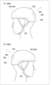
- FIG. 1 is a diagram showing a protection device according to an embodiment.
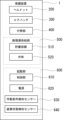
- FIG. 2 is a block diagram showing a schematic configuration of the protection device.
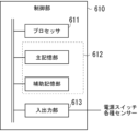
- FIG. 3 is a diagram showing the configuration of the control unit.
- FIG. 4 is a diagram showing a state in which the protection device according to the first embodiment is activated.
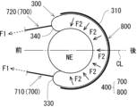
- FIG. 5 is a diagram for explaining the functions of the biasing strap and the shape maintaining portion.
- FIG. 6 is a diagram illustrating a first modified example of the protection device.
- FIG. 7 is a perspective view showing a state in which the protection device according to the second modified example is activated.
- FIG. 8 is a perspective view showing a state in which the protection device according to the fourth modified example is activated.
- FIG. 9 is a perspective view showing a state in which the protection device according to the fourth modified example is activated.
- the protection device for protecting the head and neck of a wearer is A helmet that can be worn on a wearer's head; A fixing strap for fixing the helmet to the head; an airbag housed in a folded state in a helmet before activation of the protective device; an inflation source supply unit that supplies an inflation source to the airbag when the protection device is activated; Equipped with The airbag is configured to inflate and deploy by an inflation source supplied from an inflation source supply section, thereby covering the back and both sides of the neck of the wearer,
- the seat belt further includes a biasing portion that is formed integrally with the airbag and biases the airbag against at least one of the side and back of the neck of the wearer by utilizing the inflation pressure of the airbag.
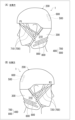
- FIG. 1 is a diagram showing a protective device 1 according to an embodiment.
- FIG. 2 is a block diagram showing a schematic configuration of the protective device 1.
- the protective device 1 is a wearable type protective device that is worn by a person to be protected, and is a device for protecting the head and neck of the wearer (person to be protected).
- the protective device 1 includes a helmet 200, an airbag 300, a biasing unit 400, an inflation source supply unit 500, an activation unit 600, and the like, which are protective equipment worn on the head of the wearer (person to be protected) and for protecting the head.
- the protective device 1 is configured to protect the neck of the wearer (person to be protected) by activating when a predetermined activation condition is met.
- the wearer who wears the protective device 1 and the person to be protected are treated as synonymous.
- the "neck” refers to a narrow part that connects the human head and the torso.
- the part of the “neck” that is mainly located on the back side of the head is called the “back neck”.
- the “back neck” may also be called the “nape”.
- the part of the “neck” that is located on the front side opposite the "posterior neck” is called the “anterior neck.”
- the “anterior neck” is sometimes also called the "anterior throat.”
- FIG. 1 in the upper part is a perspective view of the helmet 200 viewed from the left side, and (B) is a perspective view of the helmet 200 viewed from the right side.
- Fig. 1 also shows the state in which the wearer is wearing (attaching) the helmet 200.
- Fig. 1 also shows the state before the protective device 1 is activated.
- the helmet 200 in this embodiment is a half-type (approximately hemispherical) helmet.
- the helmet 200 is equipped with a fixing strap 220 for fixing the helmet 200 to the wearer (person to be protected), etc.
- the helmet 200 itself can be a known one, and an inner cushion (not shown) for absorbing shock in the event of a fall, etc. may be provided on the inside.
- the inner cushion may be made of polystyrene foam, such as expanded polystyrene beads (EPS: Expanded Poly Styrene).
- the helmet 200 may be made of, for example, ABS (Acrylonitrile Butadiene Styrene) resin or PC (Poly Carbonate) resin.
- the fixing strap 220 is a so-called chin strap.
- the fixing strap 220 is a string-like body that is hung around the wearer's chin to fix the helmet 200 to the wearer's head.
- the form of the fixing strap 220 is not particularly limited, and any known fixing strap can be used.
- the airbag 300 is a bag configured to inflate and deploy when gas, an example of an inflation source, is supplied from the inflation source supply unit 500 when the protective device 1 is activated. Before the protective device 1 is activated, the airbag 300 is stored in a folded state (i.e., in a deflated state) inside the helmet 200.
- the inflation source supply unit 500 is activated by the activation unit 600.
- the activation unit 600 activates the inflation source supply unit 500
- the inflation source supply unit 500 starts to supply gas to the airbag 300, which in turn inflates and deploys the airbag 300.
- the inflation source supply unit 500 includes a storage container 510 that stores gas in a pressurized state to be supplied to the airbag 300, and a valve body 520 that closes a gas exhaust port formed in the storage container 510.
- the storage container 510 Before the protective device 1 is activated (before the inflation source supply unit 500 is activated), the storage container 510 is sealed by the valve body 520. The sealed state of the storage container 510 is released by the opening of the valve body 520 by the activation unit 600, and the pressurized gas stored in the storage container 510 is discharged from the gas exhaust port.
- the valve body 520 may be provided with an actuator (not shown), and may be configured so that the valve body 520 is opened by the activation of the actuator.
- the operating mechanism for opening the valve body 520 of the storage container 510 is not particularly limited.
- the valve body 520 may be formed of a thin metal plate member, and the valve body 520 may be opened by the activation unit 600 operating a splitting mechanism that splits the metal plate member that constitutes the valve body 520.
- the gas exhaust port of the storage container 510 and the gas inlet port of the airbag 300 are connected to each other, and gas is supplied to the airbag 300.
- the gas exhaust port of the storage container 510 and the gas inlet port of the airbag 300 are connected, for example, by a conduit (not shown), and the gas exhausted from the gas exhaust port of the storage container 510 may be supplied to the airbag 300 through this conduit.
- the activation unit 600 is not particularly limited as long as it is capable of activating the inflation source supply unit 500, and may, for example, include a control unit 610, a power source 620, an operating condition detection sensor 630, a wearing state detection sensor 640, and the like.
- the control unit 610 is, for example, a controller (control unit) that controls the actuator of the valve body 520.
- the power source 620 is a power supply source that supplies power to the control unit 610, the operating condition detection sensor 630, the wearing state detection sensor 640, and the like, and may be, for example, a lithium-ion battery or a dry cell.
- valve body 520 When the actuator of the valve body 520 is activated by an activation command signal output from the control unit 610, the valve body 520 is opened, and as a result, the inflation source supply unit 500 is activated, and gas is supplied from the inflation source supply unit 500 to the airbag 300.
- FIG. 3 is a diagram showing the configuration of the control unit 610.
- the control unit 610 includes a processor 611, a memory unit 612, and an input/output unit 613.
- the processor 611 comprehensively executes various types of arithmetic processing in the control unit 610.
- the processor 611 may have arithmetic processing means such as a CPU (Central Processing Unit), a DSP (Digital Signal Processor), or an FPGA (Field-Programmable Gate Array).
- the memory unit 612 includes, for example, a main memory unit and an auxiliary memory unit.
- the main memory unit of the memory unit 612 includes, for example, a RAM (Random Access Memory) or a ROM (Read Only Memory), and caches information such as programs and data used in arithmetic processing by the processor 611.
- the main memory unit of the memory unit 612 may be formed integrally with the processor 611.
- the auxiliary memory unit of the memory unit 612 may be composed of, for example, a volatile memory such as a RAM, a non-volatile memory such as a ROM, or a storage medium such as an EPROM (Erasable Programmable ROM).
- the auxiliary memory unit of the memory unit 612 stores, for example, an operating system (OS), various programs, various tables, and the like for executing the operation of the protection device 1.
- the input/output unit 613 is an interface that inputs information (detection results, etc.) from various sensors such as the operating condition detection sensor 630 and the wearing state detection sensor 640, and outputs information (control signals, etc.) to various sensors and other devices.
- the protection device 1 also has a power switch (not shown), and the status signal of the power switch is also input to the input/output unit 613.
- the operating condition detection sensor 630 is a sensor for detecting that a predetermined operating condition has been met.
- the predetermined operating condition is a condition under which the protective device 1 should be activated (which can also be said to be a condition under which the inflation source supply unit 500 should be started), and examples include a fall of a bicycle ridden by a wearer wearing the helmet 200, and other conditions under which the wearer is exposed to danger.
- the operating condition detection sensor 630 may be, for example, an acceleration sensor, a gyro sensor (angular velocity sensor), etc.
- the operating condition detection sensor 630 may also be a vital sensor that detects the wearer's brain waves. The vital sensor may detect brain waves different from normal brain waves to detect a dangerous state of the wearer.
- the vital sensor may be a contact sensor that contacts the wearer's head, or a non-contact sensor.
- the operating condition detection sensor 630 may include, for example, at least one of the above-mentioned acceleration sensors, gyro sensors (angular velocity sensors), and vital sensors. Of course, the operating condition detection sensor 630 may be a combination of multiple types of sensors, including an acceleration sensor, a gyro sensor (angular velocity sensor), and a vital sensor.
- the operating condition detection sensor 630 is not particularly limited as long as it can detect the operating conditions, and can be replaced by a detection device other than the above-mentioned sensors (for example, a camera or a millimeter wave radar). Since the protection device 1 is equipped with the operating condition detection sensor 630, the activation unit 600 can activate the protection device 1 (activate the expansion source supply unit 500) at the appropriate timing.
- the wearing state detection sensor 640 is a sensor that detects the contact state between the wearer's head and the helmet 200.
- the wearing state detection sensor 640 may be, for example, a pressure sensor.
- the control unit 610 can determine whether the helmet 200 is being worn on the head based on the detection signal of the wearing state detection sensor 640.
- the wearing state detection sensor 640 may be, for example, multiple, arranged inside the helmet 200. In this case, the control unit 610 may determine that the helmet 200 is being worn when the detection signals from the multiple wearing state detection sensors 640 are signals indicating a contact state with the head.
- FIG. 4 is a diagram showing the state in which the protective device 1 according to the first embodiment is activated.
- (A) in the upper part is a perspective view of the helmet 200 viewed from the left side
- (B) is a perspective view of the helmet 200 viewed from the right side.
- the airbag 300 to which gas is supplied from the inflation source supply unit 500 is pulled out from the inner space of the helmet 200 to the outside during the process of inflation and deployment, and is deployed to protect the back of the head and neck of the wearer as shown in FIG. 4.
- the airbag 300 In the deployed state, the airbag 300 has a generally U-shaped cross section and is configured to cover the wearer's back neck and both sides of the neck.
- the airbag 300 deployed by the activation of the protective device 1 covers the wearer's neck, thereby protecting the neck of the wearer.
- the airbag 300 is configured to protect the wearer's back head by covering it in the deployed state.
- the protective device 1 includes a biasing portion 400 formed integrally with the airbag 300, which inflates and deploys the inflation source supply portion 500 when activated.
- the biasing portion 400 is a member for biasing the airbag 300 against at least one of the side and rear of the neck of the wearer by utilizing the inflation pressure of the airbag 300.
- the biasing portion 400 is stored inside the helmet 200 before the protective device 1 is activated, and is drawn out together with the airbag 300 from the inside of the helmet 200 to the outside when the protective device 1 is activated.
- the biasing portion 400 has a biasing strap 700 and a shape retaining portion 800.
- the biasing strap 700 is a string-like member having one end connected to the front positions P1 and P2 of the helmet 200 and the other end connected to the airbag 300.
- the biasing strap 700 is arranged on both the left and right sides of the helmet 200 in response to the operation of the protection device 1.
- the one arranged on the left side of the helmet 200 is called the left biasing strap 710
- the one arranged on the right side of the helmet 200 is called the right biasing strap 720.
- the biasing strap 700 is composed of a left biasing strap 710 and a right biasing strap 720.
- two left biasing straps 710 and two right biasing straps 720 are arranged on the left and right sides of the helmet 200, but the number of these is not particularly limited.
- Reference numeral 330 in FIG. 4A indicates the left front edge of the airbag 300.
- Reference numeral 340 in FIG. 4B indicates the right front edge of the airbag 300.
- the left front and right front here refer to the directions of the airbag 300 after deployment based on the front-rear and left-right directions of the helmet 200.
- one end of the left biasing strap 710 is connected to the front position P1 of the helmet 200, and the other end is connected to the left front edge 330 of the airbag 300.
- the left biasing strap 710 is configured to fit, for example, the left side of the wearer's face when the protective device 1 is activated. In the example shown in FIG.
- one end of the right biasing strap 720 is connected to the front position P2 of the helmet 200, and the other end is connected to the right front edge 340 of the airbag 300.
- the right-side biasing strap 720 is configured to fit, for example, to the right side of the wearer's face when the protection device 1 is activated.
- the material forming the biasing straps 700 is not particularly limited, but for example, cloth, rubber, wire, etc. can be used.
- the biasing straps 700 are configured to bias the airbag 300 from the rear of the wearer's neck toward the front of the neck as the protective device 1 is activated.
- the biasing straps 700 may be stored inside the helmet 200 so as to be positioned along the inside of the side opening edge of the helmet 200, and are pulled out of the helmet 200 together with the airbag 300 as the protective device 1 is activated.
- the shape retention portion 800 is configured, for example, as a frame member fixed integrally with the airbag 300, and retains the shape of the airbag 300 deployed when the protective device 1 is activated, while suppressing deformation of the airbag 300 in a direction away from the wearer's neck.
- the shape retention portion 800 is configured, for example, including an elastic metal or resin.
- two shape retention portions 800 molded into a roughly U-shape in cross section are fixed along the lateral direction of the airbag 300.
- the number, position, shape, etc. of the shape retention portions 800 provided on the airbag 300 are not particularly limited.
- the shape retention portion 800 fixed integrally with the airbag 300 is stored in the interior of the helmet 200 along the opening edge portion (for example, the rear opening edge portion) of the helmet 200 before the protective device 1 is activated. Then, it is pulled out of the helmet 200 together with the airbag 300 as the protective device 1 is activated.
- the shape retaining part 800 may form part of the outer shell of the helmet 200.
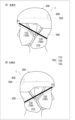
- Figure 5 is a diagram explaining the function of the biasing straps 700 (left biasing strap 710, right biasing strap 720) and shape-retaining part 800 as the biasing part 400.
- Figure 5 shows a schematic diagram of the biasing straps 700 (left biasing strap 710, right biasing strap 720) and shape-retaining part 800 biasing the airbag 300, which has been deployed when the protection device 1 is activated, toward the wearer's neck. More specifically, the cross section of the airbag 300 and biasing part 400 after deployment at the wearer's neck position is shown in schematic form. In Figure 5, the wearer's neck is indicated by the symbol NE.
- the left biasing strap 710 and the right biasing strap 720 have one end connected to the front positions P1 and P2 of the helmet 200, respectively, and the other end connected to the left front edge 330 and the right front edge 340 of the airbag 300, respectively.
- the length dimensions of the left biasing strap 710 and the right biasing strap 720 and the positions at which their one ends are attached to the helmet 200 are adjusted so that the inflation pressure of the airbag 300 acts on the left biasing strap 710 and the right biasing strap 720 during the inflation process (deployment process) of the airbag 300.
- the left side biasing strap 710 and the right side biasing strap 720 can bias the airbag 300 from the rear neck side of the wearer toward the front of the neck.
- the biasing straps 700 (left biasing strap 710, right biasing strap 720) have elasticity.
- the airbag 300 can be biased with a greater biasing force from the rear of the wearer's neck toward the front of the neck.
- the protection device 1 when activated, the restraining effect of restraining the wearer's neck can be further improved.
- FIG. 5 shows an example of the direction of the biasing force of the left biasing strap 710 and the right biasing strap 720 biasing the airbag 300 when the protection device 1 is activated.
- the symbol CL in FIG. 5 is a front-to-rear central axis that passes through the center of the helmet 200 in the left-to-right direction and extends in the front-to-rear direction.
- the front positions P1 and P2 at which one end of the left biasing strap 710 and the right biasing strap 720 are fixed to the helmet 200 may be set to a position closer to the front-to-rear central axis CL of the helmet 200 than the left front edge 330 and the right front edge 340 at which the other end of the left biasing strap 710 and the right biasing strap 720 are fixed to the airbag 300.
- the direction of the biasing force shown by the symbol F1 in FIG. 5 can be directed toward the front inside of the helmet 200.
- the "inside” refers to the inside in the left-right direction of the helmet 200, and can also be said to be the side of the front-to-rear central axis CL.
- the airbag 300 can be made to fit in a U-shape from the back of the wearer's neck to the left and right sides of the neck, further enhancing the restraining effect of restraining the wearer's neck.
- the shape-retaining part 800 is formed as a frame body having a U-shape.
- the shape-retaining part 800 is fixed integrally along the outer periphery 310 of the airbag 300.
- the outer periphery 310 of the airbag 300 refers to the part facing the opposite side to the side facing and contacting the neck of the wearer after the airbag 300 is deployed into a roughly U-shape.
- the part of the airbag 300 that faces the neck of the wearer and covers the neck after the airbag 300 is deployed into a roughly U-shape is also called the "inner periphery".
- the shape-retaining part 800 When fixing the shape-retaining part 800 to the outer periphery 310 of the airbag 300, the shape-retaining part 800 may be disposed on the outer surface (surface exposed to the outside) of the airbag 300 or on the inner surface (surface into which gas is introduced) of the airbag 300. However, the shape-retaining part 800 may be fixed along the inner periphery of the airbag 300.
- the shape-retaining portion 800 which is disposed integrally with the airbag 300, is subjected to the inflation pressure of the airbag 300 when it is inflated (deployed).
- the shape-retaining portion 800 is formed as a frame body having a U-shape, so that the shape-retaining portion 800 resists the inflation pressure of the airbag 300, retains the shape of the deployed airbag 300, and functions to suppress deformation of the airbag 300 in a direction away from the wearer's neck.
- the shape-retaining portion 800 resists the inflation pressure by its rigidity, and urges the airbag 300 toward the neck (rear neck, side neck) as a reaction force against the inflation pressure.
- the solid arrow indicated by the symbol F2 in FIG. 5 illustrates the direction of the urging force of the shape-retaining portion 800 urging the airbag 300 when the protection device 1 is activated.
- the above-mentioned shape-retaining portion 800 can maintain the airbag 300 in a state of close contact with the wearer's neck (rear neck, side neck) after inflation. As a result, the effect of restraining the wearer's neck is enhanced, and bending of the neck can be effectively suppressed.
- the shape-retaining portion 800 is fixed integrally along the outer periphery 310 of the airbag 300, so that when the protection device 1 is activated, the airbag 300 can be biased toward the wearer's neck with a larger biasing force, and the neck restraining effect of the airbag 300 can be further enhanced. In other words, excessive bending of the wearer's neck can be suitably suppressed.
- the shape-retaining portion 800 may be composed of an elastic metal or resin. In this way, when the shape-retaining portion 800 receives the inflation pressure of the airbag 300, a larger repulsive force is generated, and the airbag 300 can be biased toward the wearer's neck with a larger biasing force.
- the protective device 1 includes the airbag 300 that protects the neck of the wearer, as well as the biasing portion 400 (biasing strap 700, shape-retaining portion 800) that biases the airbag 300 toward the neck, so that a gap is unlikely to form between the airbag 300 and the neck after inflation, and the neck can be appropriately restrained.
- the protective device 1 does not need to completely restrain the movement of the wearer's head and neck when activated, and may restrain the neck with some movement.
- the protective device 1 may allow the movement of the neck so that the wearer's neck is within a range that does not receive damage when falling, etc.
- the deployed airbag 300 does not cover the entire circumference of the wearer's neck, but protects the back of the neck and both sides of the neck in a U-shape, so the wearer's throat is not excessively constricted when the protective device 1 is activated.
- one end of the biasing strap 700 that biases the airbag 300 forward is fixed to the helmet 200, and the fixing strap 220 and the airbag 300 are not particularly connected, so the wearer's throat is not excessively constricted when the protective device 1 is activated.
- the above-mentioned protective device 1 can be modified in various ways. Modified examples of the protective device 1 are described below.
- FIG. 6 is a diagram for explaining a first modification of the protective device 1.
- the helmet 200 according to the first modification is configured to cover at least the upper part of the wearer's ears when worn on the head of the wearer. That is, the helmet 200 according to the first modification has an ear cover part 210, and the ear cover part 210 covers at least the upper part of the wearer's ears when worn on the head.
- the other structures are the same as those of the protective device 1 described above.
- the biasing straps 700 left biasing strap 710, right biasing strap 720
- the helmet 200 are stored inside the helmet 200 along the side opening edge indicated by the reference numeral 230 before the protective device 1 is activated.
- the biasing straps 700 when the biasing straps 700 (left biasing strap 710, right biasing strap 720) are pulled out to the outside of the helmet 200 along with the airbag 300 that inflates and deploys when the protective device 1 is activated, the biasing straps 700 can be made less likely to get caught on the wearer's ears.
- ⁇ Second Modification> 7 is a perspective view showing a state in which the protection device 1 according to the second modification is activated.
- (A) in the upper part is a perspective view of the helmet 200 viewed from the left side
- (B) is a perspective view of the helmet 200 viewed from the right side.
- the biasing strap 700 is fixed (connected) to the outer periphery 310 of the airbag 300. That is, one end side of the biasing strap 700 is connected to the front positions P1 and P2 of the helmet 200, and the other end side of the biasing strap 700 (left side biasing strap 710, right side biasing strap 720) is connected to the outer periphery 310 of the airbag 300.
- the biasing force F1 described in FIG. 5 can be directed further inward of the helmet 200 (toward the front-rear central axis CL).
- the inflated airbag 300 can be more easily fitted to the left and right sides of the neck of the wearer.
- the airbag 300 can be more appropriately fitted in a U-shape from the back of the neck to the left and right sides of the neck of the wearer, and the restraining effect of restraining the neck of the wearer can be further improved.
- FIG. 1 In the modified example shown in FIG.
- the ends of the left biasing strap 710 and the right biasing strap 720 on the airbag 300 side may be connected to surround the entire circumferential direction of the outer periphery 310 of the airbag 300 with the biasing strap 700.
- the shape-retaining portion 800 can be used in combination with the biasing strap 700.
- FIG. 8 is a perspective view showing a state in which the protection device 1 according to the third modified example is activated.
- (A) in the upper part is a perspective view of the helmet 200 viewed from the left side
- (B) is a perspective view of the helmet 200 viewed from the right side.
- the other end side of the biasing strap 700 (left side biasing strap 710, right side biasing strap 720) is connected to the shape retaining part 800.
- one end side of the biasing strap 700 is connected to the front positions P1 and P2 of the helmet 200.
- the end of the biasing strap 700 is connected to the end 810 of the shape retaining part 800 formed into a roughly U-shape.
- an end of the biasing strap 700 is connected to an end 810 of a shape-retaining portion 800 that is integral with the airbag 300, and these are connected together.
- the shape-retaining portion 800 that is integral with the airbag 300 can be pulled directly forward by the biasing strap 700.
- the tension acting on the biasing strap 700 can be directly transmitted to the shape-retaining portion 800, so that the airbag 300 can be biased more efficiently against the wearer's back neck and neck. This further enhances the restraining effect that restrains the wearer's neck, and further improves the effect of neck protection.
- the biasing portion 400 has been described as including both the biasing straps 700 (left side biasing strap 710, right side biasing strap 720) and the shape-retaining portion 800, but this is not limited thereto, and the biasing straps 700 and the shape-retaining portion 800 can each be used alone.
- the biasing portion 400 of the protective device 1 may have only one of the biasing straps 700 and the shape-retaining portion 800.
- the inflation pressure of the airbag 300 is used to bias the airbag 300 against the wearer's neck when the protective device 1 is activated, thereby achieving a neck restraint effect.
- the directions in which the biasing straps 700 extend (the directions in which the biasing straps 700 extend and the directions in which the shape-retaining parts 800 extend, as well as their relative directions, are not particularly limited, and the embodiment shown in FIG. 8 is merely one example.
- ⁇ Fourth Modification> 9 is a perspective view showing a state in which the protection device 1 according to the fourth modification is activated.
- (A) is illustrated as a perspective view of the helmet 200 viewed from the left side
- (B) is illustrated as a perspective view of the helmet 200 viewed from the right side.
- the protection device 1 according to the fourth modification is provided with only the biasing straps 700 (left side biasing strap 710, right side biasing strap 720) as the biasing portion 400, and the shape retaining portion 800 is not provided on the airbag 300.
- an auxiliary strap 730 is integrally attached to the outer surface of the outer periphery portion 310 of the airbag 300, and the auxiliary strap 730 goes around along the outer periphery portion 310.
- Each end of the auxiliary strap 730 is continuously connected to the left side biasing strap 710 and the right side biasing strap 720. That is, the biasing strap 700 can be regarded as a single strap in which the left-side biasing strap 710, the auxiliary strap 730, and the right-side biasing strap 720 are continuous. Note that, in the example shown in Fig.
- the protection device 1 is provided with one biasing strap 700 in which the left-side biasing strap 710, the auxiliary strap 730, and the right-side biasing strap 720 are continuous, but the number of biasing straps 700 is not particularly limited, and may be two, or of course, the protection device 1 may be provided with three or more biasing straps 700.
- the biasing strap 700 configured in this manner has each end connected to the front positions P1, P2 of the helmet 200, and the auxiliary strap 730 located in the middle is joined to the outer periphery 310 of the airbag 300 and is configured to go around the outer periphery 310.
- the airbag 300 can be biased with a greater biasing force from the rear of the wearer's neck toward the front of the neck, further enhancing the restraining effect of restraining the wearer's neck when the protective device 1 is activated.
- the protective device 1 may adopt a configuration different from the above-described embodiments and each modified example.
- the activation unit 600 (control unit 610) activates the inflation source supply unit 500 based on the detection signal of the activation condition detection sensor 630.
- the helmet 200 may be provided with a manual operation unit (not shown) that is manually operated by the wearer, and the protective device 1 may be configured to operate when the wearer operates the manual operation unit.
- an appropriate mechanical mechanism for example, a combination of mechanical elements such as a spring or wire
- the protective device 1 may be operated by the wearer operating the manual operation unit.
- the specific structure of the manual operation unit is not particularly limited, and for example, a manual switch or a lock pin that can be operated by the wearer may be provided on the helmet 200, and a structure in which the gas outlet of the storage container 510 is opened by operating such a manual operation unit may be adopted.
- the inflation source supply unit 500 may be a pyrotechnic gas generator used to inflate the airbag 300.
- This type of gas generator is well known, and detailed description will be omitted.
- the gas generator may include a housing that contains a gas generating agent inside, and a pyrotechnic igniter that is activated by the supply of an operating current and ignites the gas generating agent in the housing, and may supply inflation gas generated by combustion of the gas generating agent to the airbag 300 through an appropriate conduit.
- the protective device 1 described above has been described using an example in which the airbag 300 is stored in a folded state inside the helmet 200 before activation, but the airbag 300 may be stored in a place other than the inside of the helmet 200.
- the airbag 300 may be attached to the outer shell of the helmet 200 in a state where it is covered with a cover.
- Protective device 200 Helmet 220: Fixing strap 300: Airbag 400: Pressing section 500: Inflation source supply section 700: Pressing strap 800: Shape retention section
Landscapes
- Engineering & Computer Science (AREA)
- Mechanical Engineering (AREA)
- Health & Medical Sciences (AREA)
- General Health & Medical Sciences (AREA)
- Physical Education & Sports Medicine (AREA)
- Textile Engineering (AREA)
- Business, Economics & Management (AREA)
- Emergency Management (AREA)
- Helmets And Other Head Coverings (AREA)
Abstract
Description
(態様1)
上記課題を解決するための本開示に係る技術は、
着用者の頭部および頸部を保護する保護装置であって、
着用者の頭部に装着可能なヘルメットと、
前記ヘルメットを頭部に固定するための固定用ストラップと、
前記保護装置の作動前において、前記ヘルメットに畳まれた状態で収容されたエアバッグと、
前記保護装置の作動時に、前記エアバッグに膨張源を供給する膨張源供給部と、
を備え、
前記エアバッグは、前記膨張源供給部から供給される膨張源によって膨張および展開することによって着用者の後頸部から双方の側頸部に渡りこれらを覆うように構成されており、
前記エアバッグと一体に形成されており、前記エアバッグの膨張圧を利用して当該エアバッグを着用者の側頸部および後頸部の少なくとも一方に付勢する付勢部を、更に備える。
態様1において、前記付勢部は、前記保護装置の作動前において前記ヘルメットの内空側に格納されており、前記保護装置の作動に伴って前記エアバッグと共に前記ヘルメットの内空側から外部に引き出されてもよい。
態様1又は2において、前記付勢部は、一端側が前記ヘルメットにおける前部位置に接続され、前記保護装置の作動時に着用者の後頸部側から頸部前方に向けて前記エアバッグを付勢するように構成された付勢用ストラップを含んでいてもよい。
態様3において、前記付勢用ストラップは弾性を有していてもよい。
態様3において、前記付勢用ストラップは、前記エアバッグの外周部に固定されていてもよい。
態様3において、前記ヘルメットは、着用者の頭部に装着された状態において、当該着用者における少なくとも耳の上部を覆うように構成されていてもよい。
態様1又は2において、前記付勢部は、前記保護装置の作動時に展開した前記エアバッグの形状を保持すると共に着用者の頸部から離間する方向への当該エアバッグの変形を抑制する形状保持用部を含んでいてもよい。
態様7において、前記形状保持部は、前記エアバッグにおける外周部に固定されていてもよい。
態様7において、前記形状保持部は、弾性を有する金属または樹脂を含んでいてもよい。
態様7において、前記形状保持部は、前記保護装置の作動前において前記ヘルメットの開口縁部に沿って前記ヘルメットの内空側に格納されており、前記保護装置の作動に伴って前記エアバッグと共に前記ヘルメットの内空側から外部に引き出されてもよい。
態様7において、前記付勢部は、一端側が前記ヘルメットにおける前部位置に接続され、前記保護装置の作動時に前記エアバッグを着用者の後頸部側から頸部前方に向けて付勢するように構成された付勢用ストラップを更に含み、
前記付勢用ストラップの他端側が前記形状保持部に接続されていてもよい。
態様1又は2において、前記ヘルメットに装着され、前記膨張源供給部を起動させる起動部を更に備え、
前記起動部は、所定の作動条件が成立したことを検知するための作動条件検知センサーを有していてもよい。
着用者の頭部に装着可能なヘルメットと、
ヘルメットを頭部に固定するための固定用ストラップと、
保護装置の作動前において、ヘルメットに畳まれた状態で収容されたエアバッグと、
保護装置の作動時に、エアバッグに膨張源を供給する膨張源供給部と、
を備え、
エアバッグは、膨張源供給部から供給される膨張源によって膨張および展開することによって着用者の後頸部から双方の側頸部に渡りこれらを覆うように構成されており、
エアバッグと一体に形成されており、エアバッグの膨張圧を利用して当該エアバッグを着用者の側頸部および後頸部の少なくとも一方に付勢する付勢部を、更に備える。
図1は、実施形態に係る保護装置1を示す図である。図2は、保護装置1の概略構成を示すブロック図である。保護装置1は、保護対象者に装着されるウェアラブルタイプの保護装置であり、着用者(保護対象者)の頭部および頸部を保護するための装置である。保護装置1は、着用者(保護対象者)の頭部に装着されると共に頭部を保護するための保護具であるヘルメット200、エアバッグ300、付勢部400、膨張源供給部500、起動部600等を備えている。保護装置1は、所定の作動条件が成立すると作動することによって着用者(保護対象者)の頸部を保護するように構成されている。本明細書において、保護装置1を着用する着用者と保護対象者は同義として取り扱う。また、本明細書において、「頸部」とは、ヒトの頭部と胴体を繋ぐ細くなっている部分を指す。また、「頸部」のうち、主として後頭部側に位置する部位を「後頸部」と呼ぶ。「後頸部」は「うなじ部」とも呼ばれる場合がある。また、「頸部」のうち、「後頸部」とは反対側の前側に位置する部位を「前頸部」と呼ぶ。「前頸部」は、「前喉部」とも呼ばれる場合がある。
図6は、保護装置1の第1変形例を説明する図である。第1変形例に係るヘルメット200は、着用者の頭部に装着された状態において、当該着用者における少なくとも耳の上部を覆うように構成されている。すなわち、第1変形例に係るヘルメット200は、耳カバー部210を有し、頭部への装着状態において耳カバー部210が着用者における少なくとも耳の上部を覆うようになっている。他の構造については、上述までの保護装置1と同様である。なお、付勢用ストラップ700(左側付勢用ストラップ710、右側付勢用ストラップ720)は、保護装置1の作動前において、符号230で示される側方開口縁部に沿ってヘルメット200の内側に格納されている。第1変形例に係るヘルメット200によれば、保護装置1の作動時に膨張および展開するエアバッグ300に伴って付勢用ストラップ700(左側付勢用ストラップ710、右側付勢用ストラップ720)がヘルメット200の外部に引き出される際、付勢用ストラップ700が着用者の耳に引っ掛かり難くすることができる。
図7は、第2変形例に係る保護装置1が作動した状態を示す斜視図である。上段の(A)は、ヘルメット200を左側方から眺めた斜視図として図示され、(B)は、ヘルメット200を右側方から眺めた斜視図として図示されている。図7に示す第2変形例では、付勢用ストラップ700がエアバッグ300の外周部310に固定(接続)されている。つまり、付勢用ストラップ700の一端側はヘルメット200における前部位置P1,P2に接続され、付勢用ストラップ700(左側付勢用ストラップ710、右側付勢用ストラップ720)の他端側がエアバッグ300の外周部310に接続されている。
図8は、第3変形例に係る保護装置1が作動した状態を示す斜視図である。上段の(A)は、ヘルメット200を左側方から眺めた斜視図として図示され、(B)は、ヘルメット200を右側方から眺めた斜視図として図示されている。図8に示す第3変形例では、付勢用ストラップ700(左側付勢用ストラップ710、右側付勢用ストラップ720)の他端側が形状保持部800に接続されている。なお、付勢用ストラップ700の一端側がヘルメット200における前部位置P1,P2に接続されている点については上述までの態様と同様である。また、図8に示す例では、概略U字形状に成形された形状保持部800の端部810に、付勢用ストラップ700の端部が接続されている。
図9は、第4変形例に係る保護装置1が作動した状態を示す斜視図である。上段の(A)は、ヘルメット200を左側方から眺めた斜視図として図示され、(B)は、ヘルメット200を右側方から眺めた斜視図として図示されている。第4変形例に係る保護装置1は、付勢部400として付勢用ストラップ700(左側付勢用ストラップ710、右側付勢用ストラップ720)のみが備えられ、エアバッグ300に形状保持部800は設けられていない。第4変形例においては、エアバッグ300の外周部310の外面に対して補助用ストラップ730が一体に取り付けられており、補助用ストラップ730が外周部310に沿って周回している。そして、補助用ストラップ730の各端部は左側付勢用ストラップ710、右側付勢用ストラップ720と連続的に連結されている。すなわち、付勢用ストラップ700は、左側付勢用ストラップ710、補助用ストラップ730、右側付勢用ストラップ720が連続した1本のストラップとして捉えることができる。なお、図9に示す例においては、保護装置1が、左側付勢用ストラップ710、補助用ストラップ730、右側付勢用ストラップ720が連続した付勢用ストラップ700を1本備える態様を示しているが、付勢用ストラップ700の本数は特に限定されず、2本であってもよいし、勿論、3本以上の付勢用ストラップ700を保護装置1が備えていてもよい。
200・・・ヘルメット
220・・・固定用ストラップ
300・・・エアバッグ
400・・・付勢部
500・・・膨張源供給部
700・・・付勢用ストラップ
800・・・形状保持部
Claims (12)
- 着用者の頭部および頸部を保護する保護装置であって、
着用者の頭部に装着可能なヘルメットと、
前記ヘルメットを頭部に固定するための固定用ストラップと、
前記保護装置の作動前において、前記ヘルメットに畳まれた状態で収容されたエアバッグと、
前記保護装置の作動時に、前記エアバッグに膨張源を供給する膨張源供給部と、
を備え、
前記エアバッグは、前記膨張源供給部から供給される膨張源によって膨張および展開することによって着用者の後頸部から双方の側頸部に渡りこれらを覆うように構成されており、
前記エアバッグと一体に形成されており、前記エアバッグの膨張圧を利用して当該エアバッグを着用者の側頸部および後頸部の少なくとも一方に付勢する付勢部を、更に備える、
保護装置。 - 前記付勢部は、前記保護装置の作動前において前記ヘルメットの内空側に格納されており、前記保護装置の作動に伴って前記エアバッグと共に前記ヘルメットの内空側から外部に引き出される、
請求項1に記載の保護装置。 - 前記付勢部は、一端側が前記ヘルメットにおける前部位置に接続され、前記保護装置の作動時に着用者の後頸部側から頸部前方に向けて前記エアバッグを付勢するように構成された付勢用ストラップを含む、
請求項1又は2に記載の保護装置。 - 前記付勢用ストラップは弾性を有している、請求項3に記載の保護装置。
- 前記付勢用ストラップは、前記エアバッグの外周部に固定されている、
請求項3に記載の保護装置。 - 前記ヘルメットは、着用者の頭部に装着された状態において、当該着用者における少なくとも耳の上部を覆うように構成されている、
請求項3に記載の保護装置。 - 前記付勢部は、前記保護装置の作動時に展開した前記エアバッグの形状を保持すると共に着用者の頸部から離間する方向への当該エアバッグの変形を抑制する形状保持用部を含む、
請求項1又は2に記載の保護装置。 - 前記形状保持部は、前記エアバッグにおける外周部に固定されている、
請求項7に記載の保護装置。 - 前記形状保持部は、弾性を有する金属または樹脂を含む、請求項7に記載の保護装置。
- 前記形状保持部は、前記保護装置の作動前において前記ヘルメットの開口縁部に沿って前記ヘルメットの内空側に格納されており、前記保護装置の作動に伴って前記エアバッグと共に前記ヘルメットの内空側から外部に引き出される、
請求項7に記載の保護装置。 - 前記付勢部は、一端側が前記ヘルメットにおける前部位置に接続され、前記保護装置の作動時に前記エアバッグを着用者の後頸部側から頸部前方に向けて付勢するように構成された付勢用ストラップを更に含み、
前記付勢用ストラップの他端側が前記形状保持部に接続されている、
請求項7に記載の保護装置。 - 前記ヘルメットに装着され、前記膨張源供給部を起動させる起動部を更に備え、
前記起動部は、所定の作動条件が成立したことを検知するための作動条件検知センサーを有する、
請求項1又は2に記載の保護装置。
Priority Applications (4)
| Application Number | Priority Date | Filing Date | Title |
|---|---|---|---|
| DE112024001630.8T DE112024001630T5 (de) | 2023-06-05 | 2024-03-19 | Schutzvorrichtung |
| CN202480037448.2A CN121335643A (zh) | 2023-06-05 | 2024-03-19 | 保护装置 |
| JP2025525954A JPWO2024252756A1 (ja) | 2023-06-05 | 2024-03-19 | |
| US19/406,995 US20260083202A1 (en) | 2023-06-05 | 2025-12-03 | Protection device |
Applications Claiming Priority (2)
| Application Number | Priority Date | Filing Date | Title |
|---|---|---|---|
| JP2023-092696 | 2023-06-05 | ||
| JP2023092696 | 2023-06-05 |
Related Child Applications (1)
| Application Number | Title | Priority Date | Filing Date |
|---|---|---|---|
| US19/406,995 Continuation US20260083202A1 (en) | 2023-06-05 | 2025-12-03 | Protection device |
Publications (1)
| Publication Number | Publication Date |
|---|---|
| WO2024252756A1 true WO2024252756A1 (ja) | 2024-12-12 |
Family
ID=93795731
Family Applications (1)
| Application Number | Title | Priority Date | Filing Date |
|---|---|---|---|
| PCT/JP2024/010767 Ceased WO2024252756A1 (ja) | 2023-06-05 | 2024-03-19 | 保護装置 |
Country Status (5)
| Country | Link |
|---|---|
| US (1) | US20260083202A1 (ja) |
| JP (1) | JPWO2024252756A1 (ja) |
| CN (1) | CN121335643A (ja) |
| DE (1) | DE112024001630T5 (ja) |
| WO (1) | WO2024252756A1 (ja) |
Citations (3)
| Publication number | Priority date | Publication date | Assignee | Title |
|---|---|---|---|---|
| JP2006257614A (ja) * | 2005-03-18 | 2006-09-28 | Kenji Takeuchi | 人体保護具 |
| JP2022057419A (ja) * | 2020-09-30 | 2022-04-11 | 豊田合成株式会社 | 着用エアバッグ装置 |
| JP2022525260A (ja) * | 2019-03-12 | 2022-05-11 | エヴィクス ファーム,エセ.エレ. | 急迫した衝撃からユーザの頭部領域および頸部領域を保護するための保護装置 |
Family Cites Families (31)
| Publication number | Priority date | Publication date | Assignee | Title |
|---|---|---|---|---|
| US4287613A (en) * | 1979-07-09 | 1981-09-08 | Riddell, Inc. | Headgear with energy absorbing and sizing means |
| US5546609A (en) * | 1992-01-10 | 1996-08-20 | Rush, Iii; Gus A. | Helmet |
| US5287562A (en) * | 1992-01-10 | 1994-02-22 | Rush Iii Gus A | Helmet to protect cervical spine against axial impact forces |
| US5390367A (en) * | 1992-01-10 | 1995-02-21 | Rush, Iii; Gus A. | Helmet and shoulder pads having inflatable protective means to protect cervical spine |
| US6032299A (en) * | 1995-10-30 | 2000-03-07 | Welsh; Nicole | Jacket for reducing spinal and compression injuries associated with a fall from a moving vehicle |
| US7150048B2 (en) * | 2002-12-18 | 2006-12-19 | Buckman Robert F | Method and apparatus for body impact protection |
| CA2601539A1 (en) * | 2005-03-17 | 2006-09-21 | Vision 2 International Inc. | Head protective gear |
| US7849525B2 (en) * | 2006-04-12 | 2010-12-14 | Jamshid Ghajar | Apparatus for reducing brain and cervical spine injury due to rotational movement |
| US20090064396A1 (en) * | 2007-04-11 | 2009-03-12 | Jamshid Ghajar | Apparatus for reducing brain and cervical spine injury due to rotational movement |
| US8551030B2 (en) * | 2009-11-03 | 2013-10-08 | Pemaquid Holdings Llc | Dynamically reactive spinal support system |
| US10390580B2 (en) * | 2010-09-29 | 2019-08-27 | Hövding Sverige Ab | Airbag suitable for head protection |
| US8947195B1 (en) * | 2013-01-10 | 2015-02-03 | Kiomars Anvari | Helmet impact detection and prevention mechanism to minimize head concussion |
| DE102013217851B4 (de) * | 2013-09-06 | 2025-02-20 | Robert Bosch Gmbh | Sicherheitssystem für ein Kraftrad und Auslöseverfahren eines Sicherheitssystems |
| US20150157080A1 (en) * | 2013-12-11 | 2015-06-11 | Board Of Trustees Of The Leland Stanford Junior University | Device to reduce head injury risk |
| WO2015183470A2 (en) * | 2014-05-01 | 2015-12-03 | Gruentzig Alexander | Wearable device |
| US9648914B2 (en) * | 2014-10-30 | 2017-05-16 | Elwha Llc | Systems for active coupling of airbags |
| US9730482B2 (en) * | 2014-11-20 | 2017-08-15 | Elwha Llc | System and method for airbag deployment and inflation |
| US12133566B2 (en) * | 2015-10-13 | 2024-11-05 | Sports Medicine Sciences, LLC | Fluid-based exoskeletal body armor with climate control |
| US20170309152A1 (en) * | 2016-04-20 | 2017-10-26 | Ulysses C. Dinkins | Smart safety apparatus, system and method |
| US9949516B2 (en) * | 2016-08-01 | 2018-04-24 | Joshua R&D Technologies, LLC | Interactive helmet system and method |
| SE543798C2 (en) * | 2017-06-29 | 2021-07-27 | Hoevding Sverige Ab | Protective system comprising an airbag system in the form of an inflatable helmet, a control unit and a communication interface |
| CN109259372A (zh) * | 2018-11-30 | 2019-01-25 | 闫泰行 | 一种护颈头盔 |
| US12702180B2 (en) * | 2018-12-03 | 2026-08-11 | Brian Michael Coyle | Helmet rotation damping with negative torque |
| US11464270B2 (en) * | 2018-12-03 | 2022-10-11 | Brian Michael Coyle | Rotation damping helmet |
| IT202000016930A1 (it) * | 2020-07-13 | 2022-01-13 | Alpinestars Res Spa | Dispositivo di protezione indossabile |
| US11974616B2 (en) * | 2020-09-30 | 2024-05-07 | Toyoda Gosei Co., Ltd. | Wearable airbag device |
| DE102021110249A1 (de) * | 2021-04-22 | 2022-10-27 | Autoliv Development Ab | Airbag-Helmet |
| DE102021129765B4 (de) * | 2021-11-15 | 2025-05-08 | Autoliv Development Ab | Tragbare Schutzvorrichtung |
| CN116138532A (zh) * | 2021-11-22 | 2023-05-23 | Abus·奥古斯特·布莱梅克·索恩有限股份两合公司 | 运动头盔 |
| JP2024122350A (ja) * | 2023-02-28 | 2024-09-09 | 株式会社ダイセル | 保護装置及び保護方法 |
| JP2024151722A (ja) * | 2023-04-13 | 2024-10-25 | 株式会社ダイセル | 保護装置及び保護方法 |
-
2024
- 2024-03-19 WO PCT/JP2024/010767 patent/WO2024252756A1/ja not_active Ceased
- 2024-03-19 CN CN202480037448.2A patent/CN121335643A/zh active Pending
- 2024-03-19 DE DE112024001630.8T patent/DE112024001630T5/de active Pending
- 2024-03-19 JP JP2025525954A patent/JPWO2024252756A1/ja active Pending
-
2025
- 2025-12-03 US US19/406,995 patent/US20260083202A1/en active Pending
Patent Citations (3)
| Publication number | Priority date | Publication date | Assignee | Title |
|---|---|---|---|---|
| JP2006257614A (ja) * | 2005-03-18 | 2006-09-28 | Kenji Takeuchi | 人体保護具 |
| JP2022525260A (ja) * | 2019-03-12 | 2022-05-11 | エヴィクス ファーム,エセ.エレ. | 急迫した衝撃からユーザの頭部領域および頸部領域を保護するための保護装置 |
| JP2022057419A (ja) * | 2020-09-30 | 2022-04-11 | 豊田合成株式会社 | 着用エアバッグ装置 |
Also Published As
| Publication number | Publication date |
|---|---|
| CN121335643A (zh) | 2026-01-13 |
| DE112024001630T5 (de) | 2026-03-12 |
| US20260083202A1 (en) | 2026-03-26 |
| JPWO2024252756A1 (ja) | 2024-12-12 |
Similar Documents
| Publication | Publication Date | Title |
|---|---|---|
| JP7014877B2 (ja) | エアバッグ装置およびエアバッグ装置の製造方法 | |
| US20260000143A1 (en) | Protection device and protection method | |
| JP5363649B2 (ja) | オートバイ乗りのためのエアーバッグシステム | |
| US10046726B2 (en) | Airbag safety system for a two-wheeled vehicle | |
| JP2002037003A (ja) | 膝保護用エアバッグ装置 | |
| US7600784B2 (en) | Occupant's leg restraint system | |
| CN116138532A (zh) | 运动头盔 | |
| CN112406772A (zh) | 安全气囊装置 | |
| KR102626936B1 (ko) | 에어백을 구비한 안전헬멧 | |
| KR20210009121A (ko) | 루프 에어백 장치 | |
| US20260083202A1 (en) | Protection device | |
| US7540533B2 (en) | Air bag device | |
| KR102785651B1 (ko) | 차량용 에어백 장치 | |
| JP2021139076A (ja) | 保護帽 | |
| CN121586527A (zh) | 具有头盔和气囊单元的安全装置 | |
| WO2024181501A1 (ja) | 保護装置及び保護方法 | |
| JPWO2024252756A5 (ja) | ||
| JPH0891162A (ja) | エアバッグ付きヘルメット | |
| JP2011207414A (ja) | 運転席用エアバッグ装置 | |
| JP6621345B2 (ja) | 運転席エアバッグ装置 | |
| WO2026048222A1 (ja) | 保護装置及びエアバッグの展開方法 | |
| KR100564356B1 (ko) | 조수석 에어백의 쿠션 | |
| JP2026058193A (ja) | 保護装置 | |
| WO2026069810A1 (ja) | エアバッグユニットおよび保護装置 | |
| CN212220452U (zh) | 摩托车安全气囊 |
Legal Events
| Date | Code | Title | Description |
|---|---|---|---|
| 121 | Ep: the epo has been informed by wipo that ep was designated in this application |
Ref document number: 24818995 Country of ref document: EP Kind code of ref document: A1 |
|
| ENP | Entry into the national phase |
Ref document number: 2025525954 Country of ref document: JP Kind code of ref document: A |
|
| WWE | Wipo information: entry into national phase |
Ref document number: 112024001630 Country of ref document: DE |
|
| WWP | Wipo information: published in national office |
Ref document number: 112024001630 Country of ref document: DE |
|
| 122 | Ep: pct application non-entry in european phase |
Ref document number: 24818995 Country of ref document: EP Kind code of ref document: A1 |