WO2024252790A1 - Fluid control valve, fluid control device, and protection method for fluid control valve - Google Patents
Fluid control valve, fluid control device, and protection method for fluid control valve Download PDFInfo
- Publication number
- WO2024252790A1 WO2024252790A1 PCT/JP2024/014958 JP2024014958W WO2024252790A1 WO 2024252790 A1 WO2024252790 A1 WO 2024252790A1 JP 2024014958 W JP2024014958 W JP 2024014958W WO 2024252790 A1 WO2024252790 A1 WO 2024252790A1
- Authority
- WO
- WIPO (PCT)
- Prior art keywords
- piezo
- drive voltage
- valve body
- fluid control
- piezo stack
- Prior art date
- Legal status (The legal status is an assumption and is not a legal conclusion. Google has not performed a legal analysis and makes no representation as to the accuracy of the status listed.)
- Ceased
Links
Images


Classifications
-
- F—MECHANICAL ENGINEERING; LIGHTING; HEATING; WEAPONS; BLASTING
- F16—ENGINEERING ELEMENTS AND UNITS; GENERAL MEASURES FOR PRODUCING AND MAINTAINING EFFECTIVE FUNCTIONING OF MACHINES OR INSTALLATIONS; THERMAL INSULATION IN GENERAL
- F16K—VALVES; TAPS; COCKS; ACTUATING-FLOATS; DEVICES FOR VENTING OR AERATING
- F16K31/00—Actuating devices; Operating means; Releasing devices
- F16K31/02—Actuating devices; Operating means; Releasing devices electric; magnetic
-
- H—ELECTRICITY
- H02—GENERATION; CONVERSION OR DISTRIBUTION OF ELECTRIC POWER
- H02N—ELECTRIC MACHINES NOT OTHERWISE PROVIDED FOR
- H02N2/00—Electric machines in general using piezoelectric effect, electrostriction or magnetostriction
- H02N2/02—Electric machines in general using piezoelectric effect, electrostriction or magnetostriction producing linear motion, e.g. actuators; Linear positioners ; Linear motors
- H02N2/06—Drive circuits; Control arrangements or methods
-
- H—ELECTRICITY
- H10—SEMICONDUCTOR DEVICES; ELECTRIC SOLID-STATE DEVICES NOT OTHERWISE PROVIDED FOR
- H10N—ELECTRIC SOLID-STATE DEVICES NOT OTHERWISE PROVIDED FOR
- H10N30/00—Piezoelectric or electrostrictive devices
- H10N30/20—Piezoelectric or electrostrictive devices with electrical input and mechanical output, e.g. functioning as actuators or vibrators
Definitions
- the present invention relates to a fluid control valve, a fluid control device, and a method for protecting a fluid control valve.
- Patent Document 1 describes a fluid control valve that adjusts the valve opening by applying a drive voltage to a piezoelectric actuator made up of multiple piezoelectric stacks stacked together, causing the piezoelectric stacks to expand and contract.
- piezo stacks are susceptible to degradation under high temperatures and high voltages
- the piezo stack closest to the flow path of that fluid in other words, the piezo stack closest to the valve body that constitutes the fluid control valve, becomes hotter than the other piezo stacks, and there is a risk that, for example, the piezo stack may deteriorate and short-circuit, impairing the function of the entire fluid control valve.
- the present invention was made to solve the above-mentioned problems, and its main objective is to suppress deterioration of the piezo stack close to the valve body while dispersing the stress acting on the piezo stack during expansion and contraction.
- the fluid control valve comprises a valve seat, a valve body that moves toward and away from the valve seat, and an actuator that is made up of a plurality of stacked piezo stacks and to which a drive voltage is applied to drive the valve body, and is characterized in that a first drive voltage applied to the piezo stack closest to the valve body is lower than a second drive voltage applied to any one of the other piezo stacks, at least for a predetermined period of time.
- the stress acting on the piezo stack during expansion and contraction can be dispersed.
- the first drive voltage applied to the piezo stack closest to the valve body is lower than the second drive voltage applied to any one of the other piezo stacks, deterioration of the piezo stack closest to the valve body can be suppressed even when controlling a high-temperature fluid.
- the first drive voltage may be lower than the drive voltage applied to any other piezo stack, at least for a predetermined period of time.
- the first drive voltage applied to the piezo stack closest to the valve body will be the lowest of the drive voltages applied to each piezo stack, so that deterioration of the piezo stack closest to the valve body can be more reliably suppressed.
- the thermal effect of the high-temperature fluid may extend not only to the piezo stack closest to the valve body, but also to other piezo stacks close to the valve body. Specifically, the closer the piezo stack is to the valve body, the greater the thermal effect may be. Therefore, it is preferable that the actuator has three or more piezo stacks, and that the drive voltage applied to the other piezo stacks closer to the valve body is lower than the drive voltage applied to the piezo stack farther from the valve body, at least for a predetermined period of time. In this case, for example, by changing the drive voltage depending on the distance from the valve body, it is possible to suppress deterioration of each piezo stack other than the piezo stack closest to the valve body while taking into account thermal effects.
- the multiple piezo stacks are connected in parallel to a common power source.
- the first driving voltage can be made lower than the second driving voltage with a simple circuit configuration.
- the first drive voltage even if a voltage divider circuit is used, if the original voltage of the first drive voltage and the second drive voltage becomes high, the first drive voltage also becomes high, and there is a risk that deterioration of the piezo stack close to the valve body cannot be suppressed as much as desired. Therefore, it is preferable to provide a constant voltage circuit that is interposed between the power supply and the piezo stack closest to the valve body and that keeps the first drive voltage lower than the second drive voltage. In this way, even if the base voltage becomes high, the first drive voltage is kept below a predetermined voltage, so that deterioration of the piezo stack close to the valve body can be more reliably suppressed.
- the average value of the first drive voltage applied during the drive period from the start to the end of drive of the actuator is lower than the average value of the second drive voltage applied during the drive period. In this case, since the first drive voltage is lower on average than the second drive voltage during the drive period in which the drive voltage is applied to the piezo stack, deterioration of the piezo stack close to the valve body can be suppressed.
- the fluid control valve according to the present invention is characterized in comprising: a valve seat, a valve body which moves toward and away from the valve seat, an actuator formed by stacking a plurality of piezo stacks and to which a drive voltage is applied to drive the valve body, a diagnostic piezo stack which is stacked closer to the valve body than the actuator, and a degradation diagnosis circuit which applies a diagnostic voltage different from the drive voltage to the diagnostic piezo stack.
- a fluid control valve by stacking multiple piezo stacks, the stress acting on the piezo stack during expansion and contraction can be distributed, and by using a diagnostic piezo stack and a deterioration diagnosis circuit to diagnose deterioration of the piezo stack closer to the valve body than the actuator, when controlling a high-temperature fluid, it is possible to predict the degree of deterioration of the piezo stack that is closer to the valve body among the piezo stacks that make up the actuator, and suppress deterioration of that piezo stack.
- the piezo stack closest to the valve body it is preferable to provide a sensor for detecting leakage current from the piezo stack closest to the valve body when the diagnostic voltage is applied.
- the decrease in the internal resistance of the piezo stack closest to the valve body can be used as an indication of the degree of deterioration of that piezo stack.
- the stress acting on the piezo stack during expansion and contraction can be dispersed, and since the first drive voltage is lower than the second drive voltage, deterioration of the piezo stack close to the valve body can be suppressed even when controlling a high-temperature fluid.
- the present invention configured in this way, can distribute the stress acting on the piezo stack during expansion and contraction while suppressing deterioration of the piezo stack close to the valve body.
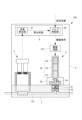
- the fluid control device 100 includes a block 1 in which an internal flow path FC is formed, a flow rate detection mechanism 2 that detects the flow rate of the fluid flowing through the internal flow path FC, a fluid control valve 3 that controls the fluid, a drive circuit 331 electrically connected to the fluid control valve 3, a housing 4 that houses the flow rate detection mechanism 2, the fluid control valve 3, and the drive circuit 331, and a control unit 5 that controls the operation of the fluid control valve 3.
- a flow rate detection mechanism 2, a fluid control valve 3, and a housing 4 are attached to the block 1.
- a high-temperature (e.g., 100 degrees or higher) process gas flows through the internal flow path FC of block 1, and to prevent the gas from being cooled, block 1 is heated to a high temperature by a heater (not shown).
- the flow rate detection mechanism 2 has a thermal flow rate detection sensor and measures the flow rate of the process gas flowing through the internal flow path FC.
- the flow rate detection sensor may be of a differential pressure type, Coriolis type, ultrasonic type, or the like.
- the fluid control valve 3 is a piezoelectric valve that controls the process gas in the internal flow path FC, and is provided downstream of the flow rate detection mechanism 2 in this example.
- the fluid control valve 3 may also be provided upstream of the flow rate detection mechanism 2.
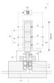
- the fluid control valve 3 is a normally closed type fluid control valve that includes a valve seat 31, a valve body 32, a piezoelectric actuator 33, a plunger 34, and a casing 35, and is configured so that the valve body 32 moves toward and away from the valve seat 31 as the piezoelectric actuator 33 expands and contracts.
- the piezo actuator 33 is held at one end of the casing 35 and extends to the other end of the casing 35, thereby pushing the valve body 32 via the plunger 34 and creating a distance between the valve seat 31 and the valve body 32.
- the other end of the casing 35 is the side where the block 1 in which the internal flow path FC is formed is provided (in other words, the side where the valve seat 31 and the valve body 32 are provided).
- the piezo actuator 33 has a plurality of piezo stacks X that expand and contract when a driving voltage greater than 0 V is applied thereto, and these piezo stacks X are stacked in the direction in which the piezo actuator 33 expands and contracts.
- a drive voltage is applied from the drive circuit 331
- the piezo stacks X expand and contract, causing the piezo actuator 33 to expand and contract.
- the piezo actuator 33 of this embodiment includes three piezo stacks X1, X2, and X3 arranged in order from bottom to top along the vertical direction.
- the upward and downward directions respectively indicate the directions toward one end and the other end of the casing 35.
- the valve seat 31 and the valve body 32 are arranged below the piezo stack X1, and the piezo stack X1 is the piezo stack X closest to the valve body 32 in this embodiment.
- the piezo stack X in FIG. 2 is arranged along the vertical direction, it may be arranged along a direction intersecting the vertical direction, for example, along the horizontal direction.
- the piezo stack X is formed, for example, by stacking multiple piezo elements, and each piezo stack X is arranged in a row so that it expands and contracts in the same direction.
- the piezo actuator 33 of this embodiment is equipped with three piezo stacks X with uniform dimensions and performance, but the dimensions and performance of each piezo stack X may be different, and it is sufficient for the piezo actuator 33 to be equipped with two or more piezo stacks X.
- the drive circuit 331 applies a drive voltage to each piezo stack X.
- This drive voltage is controlled in response to a drive signal from the control unit 5, which will be described later.
- the drive voltages applied to the three piezo stacks X1, X2, and X3 are distinguished by being called drive voltages V1, V2, and V3, respectively.
- the drive circuit 331 also has a common power supply PS to which each piezo stack X is connected in parallel, as shown in FIG. 3.
- the control unit 5 is a computer equipped with a CPU, memory, an input/output interface, etc., and by making the CPU and peripheral devices cooperate in accordance with a predetermined program stored in a predetermined area of the memory, it has at least the functions of a flow rate calculation unit 51 and a valve control unit 52, as shown in FIG. 2.
- the control unit 5 in this embodiment is housed in a housing 4 .
- the flow rate calculation unit 51 calculates the flow rate of the process gas flowing through the internal flow path FC based on the output value of the flow rate detection mechanism 2.
- the valve control unit 52 outputs a drive signal to the drive circuit 331 based on the set flow rate input from the outside and the calculated flow rate calculated by the flow rate calculation unit 51, and applies a drive voltage to each piezo stack X to adjust the valve opening of the fluid control valve 3.
- the piezo actuator 33 there is an internal flow path FC through which high-temperature process gas flows, and a block 1 that is heated by a heater to prevent the gas from liquefying.
- the piezo stack X1 which is located closest to these and closest to the valve body 32, is more likely to reach a high temperature state than the other piezo stacks X2 and X3.
- the fluid control valve 3 is configured such that, when the drive voltage V1 applied to the piezo stack X1 closest to the valve body 32 among the multiple piezo stacks X possessed by the piezo actuator 33 is defined as a first drive voltage, and the drive voltage V2 or V3 applied to either one of the other piezo stacks X2 or X3 is defined as a second drive voltage, the first drive voltage is lower than the second drive voltage for at least a predetermined period of time.
- both drive voltages V2 and V3 are second drive voltages, that is, the drive voltage V1 is configured to be lower than the drive voltages V1, V2, and V3 applied to each of the piezo stacks X1, X2, and X3 (the first drive voltage is configured to be the lowest of the drive voltages applied to each piezo stack).
- the first driving voltage does not need to be the lowest among the driving voltages applied to each piezo stack X, but it suffices if it is lower than the second driving voltage applied to at least one of the other piezo stacks X.
- the specified period may be any length such that deterioration of the piezo stack X1 closest to the valve body 32 is suppressed more than deterioration of the other piezo stacks X2 or X3, and may be, for example, more than half the driving period from the start to the end of driving of the actuator.
- the drive period may be the period from when the application of the drive voltage begins to when the application of the drive voltage ends, or it may be the period from when multiple pulsed applications of the drive voltage begin to when the application of the drive voltage ends, or it may be, for example, the period required for one step in a semiconductor manufacturing process.
- the predetermined period may also be the period during which a high drive voltage V2 or V3 (second drive voltage) is applied to the piezo stack X2 or X3, for example, the period during which the difference between the rated voltage of the piezo stack X and the second drive voltage is equal to or less than a certain value, or the period during which the ratio of the rated voltage to the second drive voltage is equal to or less than a certain value.
- V2 or V3 second drive voltage
- the average value of the first drive voltage applied during the drive period of the actuator is lower than the average value of the second drive voltage applied during the drive period.
- this embodiment includes a voltage divider circuit C1 between the power source PS that applies a drive voltage to each piezo stack X and the piezo stack X1 that is closest to the valve body 32, making the drive voltage V1 (first drive voltage) lower than the drive voltages V2 and V3 (second drive voltages).
- the drive voltage V1 applied from the power supply PS via the voltage divider circuit C1 to the piezo stack X1 closest to the valve body 32 is the first drive voltage
- the drive voltage V2 or V3 applied from the power supply PS to the other piezo stack X2 or X3 without passing through the voltage divider circuit C1 is the second drive voltage.
- the predetermined period corresponds to the entire period during which the drive voltage is applied to each piezo stack X from the power source PS.
- this voltage dividing circuit C1 has two resistors RA having the same resistance value, and the drive voltage V1 (first drive voltage) is half the drive voltages V2 and V3 (second drive voltages).
- the type and number of resistors RA constituting the voltage dividing circuit C1 may be appropriately changed in order to obtain a desired first drive voltage.
- the resistor RA may be a variable resistor.
- the fluid control valve 3 of the present embodiment configured as described above, by stacking a plurality of piezo stacks X, it is possible to disperse the stress acting on the piezo stacks X during expansion and contraction.
- the first drive voltage is lower than the second drive voltage, it is possible to suppress deterioration of the piezo stack X1 close to the valve body 32 even when controlling a high-temperature fluid.
- the first drive voltage which is lower than the second drive voltage but greater than 0 V, can be applied to the piezo stack X1 closest to the valve body 32. This makes it possible to prevent deterioration of the nearest piezo stack X1, while also achieving both space saving and ensuring the amount of expansion and contraction of the piezo actuator 33.
- the average value of the first drive voltage applied during the drive period is lower than the average value of the second drive voltage applied during the drive period, so deterioration of the piezo stack X1 close to the valve body 32 can be suppressed.
- a voltage divider circuit C1 is provided between the power supply PS and the piezo stack X1 closest to the valve body 32, so that the first drive voltage can be made lower than the second drive voltage with a simple circuit configuration.
- a piezoelectric actuator 33 in which multiple piezo stacks X are connected in parallel to a common power source PS, if even one piezo stack X suffers a malfunction such as a short circuit, the function of the entire piezo actuator 33 will be impaired, even if the other piezo stacks X are normal. As described above, the piezo stack X deteriorates quickly when a high voltage is applied in a high-temperature environment, and the piezo stack X1 close to the valve body 32 is easily exposed to high temperatures.
- the drive voltage V1 (first drive voltage) is set lower than the drive voltages V2 and V3 (second drive voltages), so that it is possible to prevent the piezo stack X1 closest to the valve body 32 from failing earlier than the other piezo stacks X2 or X3, which would result in impairment of the function of the piezo actuator 33 as a whole.
- the voltage divider circuit C1 is used to make the first drive voltage lower than the second drive voltage, but another method may be used.
- a plurality of power sources PS may be provided in the piezoelectric actuator 33, and the first drive voltage and the second drive voltage may be generated from different power sources PS.
- a first drive voltage that is lower than the second drive voltage and higher than 0 V can be freely created over a predetermined period of time, and the expansion and contraction of the piezo stack X1 closest to the valve body 32 can be freely adjusted to be used for adjusting the valve opening degree, while deterioration of this piezo stack X1 can be suppressed.
- the piezo actuator 33 as a whole can be driven by the other piezo stacks X2 or X3.
- the predetermined period can be freely set.
- a constant voltage circuit C2 that keeps the drive voltage V1 (first drive voltage) lower than the drive voltages V2 and V3 (second drive voltages) may be interposed between the power source PS and the piezo stack X1 closest to the valve body 32. If the first drive voltage is generated using the voltage divider circuit C1, the first drive voltage will also become high when the voltage of the source of the drive voltage becomes high. On the other hand, if the first drive voltage is generated using the constant voltage circuit C2, the first drive voltage will not exceed a predetermined voltage, so that deterioration of the piezo stack X1 close to the valve body 32 can be more reliably suppressed even if the source voltage becomes high.
- the predetermined voltage may be set to, for example, a value smaller than the rated voltage of the piezo stack X.
- the predetermined voltage may be set based on the drive voltage required to maximize or minimize the valve opening.
- the predetermined period is a period during which the source voltage of the drive voltage is higher than the predetermined voltage set in the constant voltage circuit C2.
- the specific circuit configuration of the constant voltage circuit C2 may be one that uses a Zener diode ZD. Note that the constant voltage circuit C2 may also be one that uses, for example, a three-terminal regulator.
- a Zener diode ZD may be connected in series to the piezo stack X1 closest to the valve body 32, or as shown in FIG. 6, a resistor RA may be connected in series to the piezo stack X1 closest to the valve body 32 and the Zener diode ZD.
- the Zener diode ZD is disposed on the power supply side, but the positional relationship of each element may be changed as appropriate.
- the predetermined period is the entire period during which the drive voltage is applied to each piezo stack X from the power source PS.
- the first drive voltage is maintained higher than 0 V by the voltage divider circuit C1 for a predetermined period of time, but the first drive voltage may be 0 V.
- applying the first drive voltage also includes not applying the drive voltage for a predetermined period of time. In this case, the deterioration of the piezo stack X1 close to the valve body 32 can be more reliably suppressed.
- a configuration may be adopted in which the drive voltage is not always applied to the piezo stack X1 closest to the valve body 32, and for example, the piezo stack X1 does not have to be connected to the power source PS.
- the piezo stack X1 closest to the valve body 32 is not connected to a power source in parallel with the other piezo stacks X2 and X3, so even if the piezo stack X1 closest to the valve body 32 is affected by heat and short-circuits or the like, the valve opening adjustment function of the entire piezo actuator 33 is not impaired.
- the piezo actuator 33 has three piezo stacks X as in the above embodiment, it is preferable that, among the other piezo stacks X2 or X3, the drive voltage V2 applied to the piezo stack X2 closer to the valve body 32 is lower than the drive voltage V3 applied to the piezo stack X3 farther from the valve body 32 for at least a predetermined period of time. In this way, it is possible to suppress deterioration not only of the piezo stack X1 closest to the valve body 32, but also of the piezo stack X2 second closest to the valve body 32.
- the first drive voltage may be applied collectively to a plurality of continuously stacked piezo stacks X, including the piezo stack X1 closest to the valve body 32.
- the drive voltages V1 and V2 applied to the piezo stacks X1 and X2 in the above embodiment may be the first drive voltage. In this way, deterioration of the multiple piezo stacks X arranged closer to the valve body 32 can be suppressed collectively.
- a first drive voltage lower than the second drive voltage applied to at least one of the other piezo stacks X is applied to the piezo stack X1 closest to the valve body 32.
- the piezo stacks X may be configured such that, of two piezo stacks X included in the plurality of piezo stacks X, the drive voltage applied to one of the piezo stacks X closer to the valve body 32 is lower than the drive voltage applied to the other piezo stack X farther from the valve body 32.
- the fluid control valve 3 of the second embodiment differs from that of the first embodiment in that it further includes a diagnostic piezo stack Y and a deterioration diagnosis circuit C3, and in that the control unit 5 has a deterioration diagnosis function.
- a diagnostic piezo stack Y and a deterioration diagnosis circuit C3
- the control unit 5 has a deterioration diagnosis function.
- the fluid control valve 3 of the second embodiment includes a diagnostic piezo stack Y that is stacked closer to the valve body 32 than the piezo actuator 33 is.
- the diagnostic piezo stack Y in this embodiment is located below the piezo actuator 33 and is sandwiched between the piezo actuator 33 and the valve body 32.
- the diagnostic piezo stack Y is provided integrally with the multiple piezo stacks X that constitute the piezo actuator 33, but may be provided separately.
- the leakage current is the current flowing through the diagnostic piezo stack Y, which increases as the diagnostic piezo stack Y deteriorates and its resistance decreases.
- the degradation diagnosis circuit C3 applies a diagnostic voltage D to the diagnostic piezo stack Y in response to a diagnostic signal from the control unit 5, which will be described later.
- the current sensor A detects a current leaking from the diagnostic piezo stack Y, and outputs a signal indicating the detected value to the control unit 5.
- the diagnostic voltage D may be applied to the diagnostic piezo stack Y continuously or intermittently at a predetermined voltage. Also, it may be applied only when diagnosis is desired.
- the diagnostic voltage D is preferably lower than the drive voltage so that the diagnostic piezo stack Y does not deteriorate quickly.
- the driving circuit 331 is not connected to the diagnostic piezo stack Y, and no driving voltage is applied to it.
- the control unit 5 of the second embodiment has at least the functions of a flow rate calculation unit 51, a valve control unit 52, a diagnostic voltage control unit 53, a memory unit 54, and a degradation diagnosis unit 55.
- the diagnostic voltage control unit 53 outputs a diagnostic signal to the degradation diagnostic circuit C3 based on a diagnostic command input from the outside, and controls the diagnostic voltage D.
- the memory unit 54 stores reference values for diagnosing the degree of deterioration of the piezo stack X.
- Degradation diagnostic unit 55 compares the detection value indicated by the signal from degradation diagnostic circuit C3 with a reference value stored in memory unit 54 to diagnose the degree of degradation of diagnostic piezo stack Y.
- the deterioration diagnosis unit 55 outputs the degree of deterioration of the diagnostic piezo stack Y as a diagnosis result.
- the deterioration degree of the piezo stack X constituting the piezo actuator 33 may be predicted from the deterioration degree of the diagnostic piezo stack Y and output as a diagnosis result.
- the fluid control valve 3 of this embodiment configured in this manner, by stacking a plurality of piezo stacks X, it is possible to disperse the stress acting on the piezo stack X during expansion and contraction.
- the deterioration diagnosis circuit C3 to diagnose the deterioration of the diagnostic piezo stack Y that is stacked closer to the valve body 32 than the piezo actuator 33, it is possible, when controlling a high-temperature fluid, to predict the degree of deterioration of the piezo stack X that is closer to the valve body, among the piezo stacks X that constitute the piezo actuator 33, and to suppress the deterioration of that piezo stack X.
- a sensor is provided to detect leakage current from the diagnostic piezo stack Y, so that a decrease in the internal resistance of the diagnostic piezo stack Y can be used for diagnosis as an indication of the degree of deterioration of the piezo stack X that constitutes the piezo actuator 33.
- only one diagnostic piezo stack Y is disposed below the piezo actuator 33, but an additional diagnostic piezo stack Y may be provided in the same position or in another position.
- an additional diagnostic piezo stack Y is provided above the piezo actuator 33, it is possible to predict the degree of deterioration of the piezo stack X that is far from the valve body among the multiple piezo stacks X that make up the piezo actuator 33, and to know the difference in the degree of deterioration between this and the piezo stacks closer to the valve body.
- the additional diagnostic piezo stack Y is sandwiched between a plurality of piezo stacks X that constitute the piezo actuator 33, the degree of deterioration of the two piezo stacks X adjacent to the additional diagnostic piezo stack Y can be predicted.
- the present invention by stacking multiple piezo stacks, it is possible to disperse the stress acting on the piezo stack during expansion and contraction.
- the first drive voltage applied to the piezo stack closest to the valve body is lower than the second drive voltage applied to any one of the other piezo stacks, it is possible to suppress deterioration of the piezo stack closest to the valve body even when controlling a high-temperature fluid.
Landscapes
- Engineering & Computer Science (AREA)
- General Engineering & Computer Science (AREA)
- Mechanical Engineering (AREA)
- Electrically Driven Valve-Operating Means (AREA)
Abstract
Description
本発明は、流体制御弁、流体制御装置、及び、流体制御弁の保護方法に関するものである。 The present invention relates to a fluid control valve, a fluid control device, and a method for protecting a fluid control valve.
特許文献1には、複数のピエゾスタックが積層されてなるピエゾアクチュエータに駆動電圧を印加して、ピエゾスタックを伸縮させることで、弁開度を調整する流体制御弁が記載されている。 Patent Document 1 describes a fluid control valve that adjusts the valve opening by applying a drive voltage to a piezoelectric actuator made up of multiple piezoelectric stacks stacked together, causing the piezoelectric stacks to expand and contract.
このように複数のピエゾスタックを伸縮させて弁開度を調整する構成にすることで、単一のピエゾスタックを伸縮させて弁開度を調整する構成に比べて、伸縮時にピエゾスタックに作用する応力を分散させることができる。 By configuring multiple piezo stacks in this way to adjust the valve opening by expanding and contracting, it is possible to disperse the stress acting on the piezo stacks during expansion and contraction, compared to a configuration in which a single piezo stack is expanded and contracted to adjust the valve opening.
しかしながら、ピエゾスタックは高温高電圧下で劣化しやすいところ、上述したピエゾアクチュエータを用いて高温の流体を制御する場合、その流体の流路に近いピエゾスタック、言い換えれば、流体制御弁を構成する弁体に最も近いピエゾスタックが、他のピエゾスタックよりも高温になり、例えば、そのピエゾスタックが劣化により短絡して、流体制御弁全体の機能が損なわれてしまう恐れがある。 However, since piezo stacks are susceptible to degradation under high temperatures and high voltages, when the above-mentioned piezo actuator is used to control a high-temperature fluid, the piezo stack closest to the flow path of that fluid, in other words, the piezo stack closest to the valve body that constitutes the fluid control valve, becomes hotter than the other piezo stacks, and there is a risk that, for example, the piezo stack may deteriorate and short-circuit, impairing the function of the entire fluid control valve.
そこで本発明は、上述した課題を解決するべくなされたものであり、伸縮時にピエゾスタックに作用する応力を分散しつつ、弁体に近いピエゾスタックの劣化を抑制することをその主たる課題とするものである。 The present invention was made to solve the above-mentioned problems, and its main objective is to suppress deterioration of the piezo stack close to the valve body while dispersing the stress acting on the piezo stack during expansion and contraction.
すなわち、本発明に係る流体制御弁は、弁座と、弁座に対して接離する弁体と、複数のピエゾスタックが積層されてなり、駆動電圧が印加されて弁体を駆動させるアクチュエータとを備え、前記弁体に最も近い前記ピエゾスタックに印加される第1駆動電圧が、少なくとも所定期間に亘り、その他の前記ピエゾスタックいずれか一つに印加される第2駆動電圧よりも低いことを特徴とするものである。 In other words, the fluid control valve according to the present invention comprises a valve seat, a valve body that moves toward and away from the valve seat, and an actuator that is made up of a plurality of stacked piezo stacks and to which a drive voltage is applied to drive the valve body, and is characterized in that a first drive voltage applied to the piezo stack closest to the valve body is lower than a second drive voltage applied to any one of the other piezo stacks, at least for a predetermined period of time.
このような流体制御弁であれば、複数のピエゾスタックを積層することで伸縮時にピエゾスタックに作用する応力を分散させることができる。また、弁体に最も近い前記ピエゾスタックに印加される第1駆動電圧を、その他の前記ピエゾスタックいずれか一つに印加される第2駆動電圧よりも低くしているので、高温の流体を制御する場合であっても、弁体に近いピエゾスタックの劣化を抑制することができる。 In such a fluid control valve, by stacking multiple piezo stacks, the stress acting on the piezo stack during expansion and contraction can be dispersed. In addition, since the first drive voltage applied to the piezo stack closest to the valve body is lower than the second drive voltage applied to any one of the other piezo stacks, deterioration of the piezo stack closest to the valve body can be suppressed even when controlling a high-temperature fluid.
第1駆動電圧が、少なくとも所定期間に亘り、その他のピエゾスタックいずれに印加される駆動電圧よりも低いとよい。
これならば、弁体に最も近い前記ピエゾスタックに印加される第1駆動電圧が、各ピエゾスタックに印加される駆動電圧の中で一番低くなるので、より確実に弁体に近いピエゾスタックの劣化を抑制することができる。
The first drive voltage may be lower than the drive voltage applied to any other piezo stack, at least for a predetermined period of time.
In this case, the first drive voltage applied to the piezo stack closest to the valve body will be the lowest of the drive voltages applied to each piezo stack, so that deterioration of the piezo stack closest to the valve body can be more reliably suppressed.
高温の流体による熱影響は、弁体に最も近いピエゾスタックだけでなく、弁体に近いその他のピエゾスタックにも及びうる。具体的には、弁体に近いピエゾスタックほど、大きな熱影響を受け得る。
そこで、前記アクチュエータは、3以上のピエゾスタックを有し、前記その他のピエゾスタックのうち、前記弁体に近いピエゾスタックに印加される駆動電圧が、少なくとも所定期間に亘り、前記弁体から遠いピエゾスタックに印加される駆動電圧よりも低いことが好ましい。
これならば、例えば、弁体からの距離に応じて駆動電圧を変えることで、熱影響を考慮した上で弁体に最も近いピエゾスタック以外の各ピエゾスタックの劣化も抑制できる。
The thermal effect of the high-temperature fluid may extend not only to the piezo stack closest to the valve body, but also to other piezo stacks close to the valve body. Specifically, the closer the piezo stack is to the valve body, the greater the thermal effect may be.
Therefore, it is preferable that the actuator has three or more piezo stacks, and that the drive voltage applied to the other piezo stacks closer to the valve body is lower than the drive voltage applied to the piezo stack farther from the valve body, at least for a predetermined period of time.
In this case, for example, by changing the drive voltage depending on the distance from the valve body, it is possible to suppress deterioration of each piezo stack other than the piezo stack closest to the valve body while taking into account thermal effects.
部品点数やコストの削減を図るためには、前記複数のピエゾスタックが、共通の電源に並列で接続されていることが好ましい。 In order to reduce the number of parts and costs, it is preferable that the multiple piezo stacks are connected in parallel to a common power source.
前記電源と、前記弁体に最も近いピエゾスタックとの間に介在する分圧回路を備えることが好ましい。
これならば、単純な回路構成で、第1駆動電圧を第2駆動電圧よりも低くすることができる。
It is preferable to include a voltage divider circuit interposed between the power supply and the piezo stack closest to the valve body.
In this case, the first driving voltage can be made lower than the second driving voltage with a simple circuit configuration.
ところで、分圧回路を用いたとしても、第1駆動電圧及び第2駆動電圧の大元の電圧が高くなれば、第1駆動電圧も高電圧になり、弁体に近いピエゾスタックの劣化を思う程は抑制できない恐れがある。
そこで、前記電源と、前記弁体に最も近いピエゾスタックとの間に介在し、前記第1駆動電圧を前記第2駆動電圧よりも低く保つ定電圧回路を備えることが好ましい。
これならば、大元の電圧が高くなっても、第1駆動電圧は所定の電圧以下に保たれるので、弁体に近いピエゾスタックの劣化をより確実に抑制することができる。
However, even if a voltage divider circuit is used, if the original voltage of the first drive voltage and the second drive voltage becomes high, the first drive voltage also becomes high, and there is a risk that deterioration of the piezo stack close to the valve body cannot be suppressed as much as desired.
Therefore, it is preferable to provide a constant voltage circuit that is interposed between the power supply and the piezo stack closest to the valve body and that keeps the first drive voltage lower than the second drive voltage.
In this way, even if the base voltage becomes high, the first drive voltage is kept below a predetermined voltage, so that deterioration of the piezo stack close to the valve body can be more reliably suppressed.
ところで、所定期間に亘って第1駆動電圧を第2駆動電圧よりも低くしても、仮に、それ以外の期間において、第2駆動電圧よりも高い第1駆動電圧が長期間に亘って印加されていたら、弁体に近いピエゾスタックの劣化は、思う程は抑制することができない。
そこで、前記アクチュエータの駆動開始から駆動終了までの駆動期間に印加する前記第1駆動電圧の平均値が、該駆動期間に印加する前記第2駆動電圧の平均値よりも低いことが好ましい。
これならば、ピエゾスタックに駆動電圧が印加される駆動期間において、第1駆動電圧が第2駆動電圧よりも平均して低くなるので、弁体に近いピエゾスタックの劣化を抑制することができる。
However, even if the first drive voltage is made lower than the second drive voltage for a specified period of time, if the first drive voltage higher than the second drive voltage is applied for a long period of time during other periods, the deterioration of the piezo stack close to the valve body cannot be suppressed as much as desired.
Therefore, it is preferable that the average value of the first drive voltage applied during the drive period from the start to the end of drive of the actuator is lower than the average value of the second drive voltage applied during the drive period.
In this case, since the first drive voltage is lower on average than the second drive voltage during the drive period in which the drive voltage is applied to the piezo stack, deterioration of the piezo stack close to the valve body can be suppressed.
また、本発明に係る流体制御弁は、弁座と、前記弁座に対して接離する弁体と、複数のピエゾスタックが積層されてなり、駆動電圧が印加されて前記弁体を駆動させるアクチュエータとを備え、前記複数のピエゾスタックに含まれる2つのピエゾスタックのうち、前記弁体に近いピエゾスタックに印加される駆動電圧が、前記弁体から遠いピエゾスタックに印加される駆動電圧よりも低いことを特徴とするものである。
このような流体制御弁であれば、複数のピエゾスタックを積層することで、伸縮時にピエゾスタックに作用する応力を分散させることができるうえ、弁体に近いピエゾスタックが、弁体から遠いピエゾスタックよりも劣化が早く進むのを抑制できる。
In addition, the fluid control valve according to the present invention comprises a valve seat, a valve body which moves toward and away from the valve seat, and an actuator which is formed by stacking a plurality of piezo stacks and to which a drive voltage is applied to drive the valve body, and is characterized in that, of two piezo stacks included in the plurality of piezo stacks, the drive voltage applied to the piezo stack closer to the valve body is lower than the drive voltage applied to the piezo stack farther from the valve body.
In such a fluid control valve, by stacking multiple piezo stacks, the stress acting on the piezo stacks during expansion and contraction can be dispersed, and the piezo stacks closer to the valve body can be prevented from deteriorating more rapidly than the piezo stacks farther from the valve body.
また、本発明に係る流体制御弁は、弁座と、弁座に対して接離する弁体と、複数のピエゾスタックが積層されてなり、駆動電圧が印加されて弁体を駆動させるアクチュエータと、前記アクチュエータよりも前記弁体に近い側に積層されている診断用ピエゾスタックと、前記診断用ピエゾスタックに前記駆動電圧とは別の診断電圧を印加する劣化診断回路とを備えていることを特徴とするものである。
このような流体制御弁であれば、複数のピエゾスタックを積層することで、伸縮時にピエゾスタックに作用する応力を分散させることができるうえ、診断用ピエゾスタック及び劣化診断回路を用いてアクチュエータよりも弁体に近い側のピエゾスタックの劣化を診断することで、高温の流体を制御する場合には、アクチュエータを構成するピエゾスタックのうち、弁体に近いピエゾスタックの劣化度合いを予測しつつ、そのピエゾスタックの劣化を抑制することが可能となる。
Furthermore, the fluid control valve according to the present invention is characterized in comprising: a valve seat, a valve body which moves toward and away from the valve seat, an actuator formed by stacking a plurality of piezo stacks and to which a drive voltage is applied to drive the valve body, a diagnostic piezo stack which is stacked closer to the valve body than the actuator, and a degradation diagnosis circuit which applies a diagnostic voltage different from the drive voltage to the diagnostic piezo stack.
In such a fluid control valve, by stacking multiple piezo stacks, the stress acting on the piezo stack during expansion and contraction can be distributed, and by using a diagnostic piezo stack and a deterioration diagnosis circuit to diagnose deterioration of the piezo stack closer to the valve body than the actuator, when controlling a high-temperature fluid, it is possible to predict the degree of deterioration of the piezo stack that is closer to the valve body among the piezo stacks that make up the actuator, and suppress deterioration of that piezo stack.
前記診断電圧が印加される際に、前記弁体に最も近い前記ピエゾスタックからのリーク電流を検知するセンサを備えていることが好ましい。
これならば、弁体に最も近いピエゾスタックの内部抵抗の低下を、そのピエゾスタックの劣化度合いとして利用することができる。
It is preferable to provide a sensor for detecting leakage current from the piezo stack closest to the valve body when the diagnostic voltage is applied.
In this case, the decrease in the internal resistance of the piezo stack closest to the valve body can be used as an indication of the degree of deterioration of that piezo stack.
さらに、本発明に係る流体制御装置は、上述した流体制御弁を備えることを特徴とするものである。
このような流体制御装置であれば、上述した流体制御弁と同様の作用効果を奏し得る。
Furthermore, a fluid control device according to the present invention is characterized by comprising the above-mentioned fluid control valve.
Such a fluid control device can achieve the same effects as the above-mentioned fluid control valve.
加えて、本発明に係る流体制御弁の保護方法は、弁座と、前記弁座に対して接離する弁体と、複数のピエゾスタックが積層されてなり、駆動電圧が印加されて前記弁体を駆動させるアクチュエータとを備える、流体制御弁の保護方法であって、前記弁体に最も近い前記ピエゾスタックに印加される第1駆動電圧が、少なくとも所定期間に亘り、その他の前記ピエゾスタックいずれか一つに印加される第2駆動電圧よりも低いことを特徴とする方法である。
このような方法によれば、複数のピエゾスタックを積層することで、伸縮時にピエゾスタックに作用する応力を分散させることができるうえ、第1駆動電圧を第2駆動電圧よりも低くしているので、高温の流体を制御する場合であっても、弁体に近いピエゾスタックの劣化を抑制することができる。
In addition, the method for protecting a fluid control valve according to the present invention is a method for protecting a fluid control valve comprising a valve seat, a valve body that moves toward and away from the valve seat, and an actuator formed by stacking a plurality of piezo stacks and to which a drive voltage is applied to drive the valve body, characterized in that a first drive voltage applied to the piezo stack closest to the valve body is lower than a second drive voltage applied to any one of the other piezo stacks, for at least a predetermined period of time.
According to this method, by stacking multiple piezo stacks, the stress acting on the piezo stack during expansion and contraction can be dispersed, and since the first drive voltage is lower than the second drive voltage, deterioration of the piezo stack close to the valve body can be suppressed even when controlling a high-temperature fluid.
また、本発明に係る流体制御弁の保護方法は、弁座と、前記弁座に対して接離する弁体と、複数のピエゾスタックが積層されてなり、駆動電圧が印加されて前記弁体を駆動させるアクチュエータとを備える、流体制御弁の保護方法であって、前記アクチュエータよりも前記弁体に近い側に積層されている診断用ピエゾスタックに、前記駆動電圧とは別の診断電圧が印加されることを特徴とする方法である。
このような方法によれば、複数のピエゾスタックを積層することで、伸縮時にピエゾスタックに作用する応力を分散させることができるうえ、診断用ピエゾスタック及び劣化診断回路を用いてアクチュエータよりも弁体に近い側のピエゾスタックの劣化を診断することで、高温の流体を制御する場合には、アクチュエータを構成するピエゾスタックのうち、弁体に近いピエゾスタックの劣化度合いを予測しつつ、そのピエゾスタックの劣化を抑制することが可能となる。
Furthermore, the method for protecting a fluid control valve according to the present invention is a method for protecting a fluid control valve comprising a valve seat, a valve body that moves toward and away from the valve seat, and an actuator formed by stacking a plurality of piezo stacks and to which a drive voltage is applied to drive the valve body, characterized in that a diagnostic voltage different from the drive voltage is applied to a diagnostic piezo stack that is stacked closer to the valve body than the actuator.
According to this method, by stacking multiple piezo stacks, it is possible to distribute the stress acting on the piezo stack during expansion and contraction, and by diagnosing the deterioration of the piezo stack closer to the valve body than the actuator using a diagnostic piezo stack and a deterioration diagnosis circuit, when controlling a high-temperature fluid, it is possible to predict the degree of deterioration of the piezo stack closest to the valve body among the piezo stacks that make up the actuator, and suppress the deterioration of that piezo stack.
このように構成した本発明によれば、伸縮時にピエゾスタックに作用する応力を分散しつつ、弁体に近いピエゾスタックの劣化を抑制することができる。 The present invention, configured in this way, can distribute the stress acting on the piezo stack during expansion and contraction while suppressing deterioration of the piezo stack close to the valve body.
<第1実施形態の装置構成>
本発明に係る流体制御弁3の第1実施形態について図面を参照して説明する。
<Device configuration of the first embodiment>
A first embodiment of a
本実施形態の流体制御弁3は、例えば、半導体製造プロセスにおいて、チャンバに供給するプロセスガス等の流体の流量を制御する流体制御装置100に用いられるものである。
The
図1に示すように、流体制御装置100は、内部流路FCが形成されたブロック1と、内部流路FCを流れる流体の流量を検知する流量検知機構2と、その流体を制御する流体制御弁3と、流体制御弁3と電気的に接続された駆動回路331と、流量検知機構2及び流体制御弁3及び駆動回路331を収容する筐体4と、流体制御弁3の動作を制御する制御部5と、を備えている。
As shown in FIG. 1, the
ブロック1には、流量検知機構2と、流体制御弁3と、筐体4とが取り付けられている。
本実施形態では、ブロック1の内部流路FCには高温(例えば100度以上)のプロセスガスが流れており、そのガスが冷却されてしまわないように、このブロック1は、図示しないヒータによって高温に加熱されている。
A flow
In this embodiment, a high-temperature (e.g., 100 degrees or higher) process gas flows through the internal flow path FC of block 1, and to prevent the gas from being cooled, block 1 is heated to a high temperature by a heater (not shown).
流量検知機構2は、ここでは熱式流量検知センサを有しており、内部流路FCを流れるプロセスガスの流量を測定するものである。流量検知センサは、差圧式、コリオリ式、又は超音波式などを用いても良い。
The flow
流体制御弁3は、内部流路FCのプロセスガスを制御するピエゾバルブであり、ここでは流量検知機構2の下流側に設けられている。流体制御弁3は、流量検知機構2の上流側に設けられていても良い。
The
流体制御弁3は、図2に示すように、弁座31と、弁体32と、ピエゾアクチュエータ33と、プランジャ34と、ケーシング35と、を備え、ピエゾアクチュエータ33が伸縮することにより、弁体32が弁座31に対して接離するように構成されたノーマルクローズ型の流体制御弁である。
As shown in FIG. 2, the
より具体的には、ピエゾアクチュエータ33は、ケーシング35の一端側に保持されて、ケーシング35の他端側に伸長することで、プランジャ34を介して弁体32を押して弁座31と弁体32との間に距離を生じさせる。ここで、ケーシング35の他端側は、内部流路FCが形成されたブロック1が設けられている側(言い換えれば、弁座31及び弁体32が設けられている側)である。
More specifically, the
ピエゾアクチュエータ33は、0Vより大きい駆動電圧が印加されることで伸縮する複数のピエゾスタックXを有しており、これらのピエゾスタックXは、ピエゾアクチュエータ33の伸縮方向に沿って積層されている。
駆動回路331から駆動電圧が印加される際に、これらのピエゾスタックXが伸縮することで、ピエゾアクチュエータ33は伸縮する。
The
When a drive voltage is applied from the
本実施形態のピエゾアクチュエータ33は、図2に示すように、上下方向に沿って下から上に順に配置された3つのピエゾスタックX1、X2、X3を備えている。ここで、上方向及び下方向は、それぞれケーシング35の一端側方向及び他端側方向を示す。ピエゾスタックX1の下方に弁座31及び弁体32が配置されており、ピエゾスタックX1は、ここでは、弁体32に最も近いピエゾスタックXである。
図2のピエゾスタックXは上下方向に沿って配置されたものであったが、鉛直方向と交差する方向、例えば水平方向に沿って配置されてもよい。
2, the
Although the piezo stack X in FIG. 2 is arranged along the vertical direction, it may be arranged along a direction intersecting the vertical direction, for example, along the horizontal direction.
ピエゾスタックXは、例えば、ピエゾ素子を複数枚積層して形成されたものであり、各ピエゾスタックXは、それぞれ同一方向に沿って伸縮するように一列に並べられている。 The piezo stack X is formed, for example, by stacking multiple piezo elements, and each piezo stack X is arranged in a row so that it expands and contracts in the same direction.
また、本実施形態のピエゾアクチュエータ33は、寸法や性能などが統一された3つのピエゾスタックXを備えているが、寸法や性能は各ピエゾスタックXで異なっていても良く、2以上のピエゾスタックXを備えたピエゾアクチュエータ33であれば良い。
In addition, the
駆動回路331は、図2に示すように、駆動電圧を各ピエゾスタックXに印加するものである。この駆動電圧は、後述する制御部5からの駆動信号に応じて制御される。
本実施形態では、3つのピエゾスタックX1、X2、X3に印加される駆動電圧を、それぞれ駆動電圧V1、V2、V3と呼んで区別する。
2, the
In this embodiment, the drive voltages applied to the three piezo stacks X1, X2, and X3 are distinguished by being called drive voltages V1, V2, and V3, respectively.
また駆動回路331は、図3に示すように、各ピエゾスタックXが並列に接続される共通の電源PSを有している。
The
制御部5は、CPU、メモリ、入出力インターフェース等を備えたコンピュータであり、メモリの所定領域に記憶させた所定のプログラムにしたがって、CPUや周辺機器を協働させることにより、図2に示すように、少なくとも、流量算出部51及びバルブ制御部52としての機能を備えている。
本実施形態の制御部5は筐体4に収容されている。
The
The
流量算出部51は、図1に示すように、流量検知機構2の出力値に基づいて、内部流路FCを流れるプロセスガスの流量を算出する。
As shown in FIG. 1, the flow
バルブ制御部52は、図1に示すように、外部から入力される設定流量と、流量算出部51が算出した算出流量とに基づいて、駆動回路331に駆動信号を出力し、各ピエゾスタックXに駆動電圧を印加させて、流体制御弁3の弁開度を調整するものである。
As shown in FIG. 1, the
ところで、本実施形態では、ピエゾアクチュエータ33の下方には、高温のプロセスガスが流れる内部流路FCと、ガスの液化防止用のヒータによって加熱されているブロック1とがあり、これらに最も近い位置に配置される、弁体32に最も近いピエゾスタックX1は、他のピエゾスタックX2及びX3と比べて高温状態になりやすい。
In this embodiment, below the
しかして、流体制御弁3は、ピエゾアクチュエータ33が有する複数のピエゾスタックXのうち、弁体32に最も近いピエゾスタックX1に印加される駆動電圧V1を第1駆動電圧とし、その他のピエゾスタックX2又はX3のいずれか一つに印加される駆動電圧V2又はV3を第2駆動電圧とすると、第1駆動電圧が、少なくとも所定期間に亘り、第2駆動電圧よりも低くなるように構成されている。
特に本実施形態では、駆動電圧V2及びV3の両方が第2駆動電圧であり、つまり駆動電圧V1は、各ピエゾスタックX1、X2、X3いずれに印加される駆動電圧V1、V2、V3よりも低くなるように(第1駆動電圧が、各ピエゾスタックに印加される駆動電圧の中で一番低くなるように)構成されている。
但し、第1駆動電圧は、各ピエゾスタックXに印加される駆動電圧の中で一番低いものである必要はなく、少なくとも他のピエゾスタックXのいずれか一つに印加される第2駆動電圧よりも低いものであれば良い。
Thus, the
In particular, in this embodiment, both drive voltages V2 and V3 are second drive voltages, that is, the drive voltage V1 is configured to be lower than the drive voltages V1, V2, and V3 applied to each of the piezo stacks X1, X2, and X3 (the first drive voltage is configured to be the lowest of the drive voltages applied to each piezo stack).
However, the first driving voltage does not need to be the lowest among the driving voltages applied to each piezo stack X, but it suffices if it is lower than the second driving voltage applied to at least one of the other piezo stacks X.
所定期間は、弁体32に最も近いピエゾスタックX1の劣化が、その他のピエゾスタックX2又はX3の劣化よりも抑制されるような長さであればよく、例えば、アクチュエータの駆動開始から駆動終了までの駆動期間の半分以上であればよい。
ここで、駆動期間とは、駆動電圧が印加され始めてから、その駆動電圧の印加が終了するまでの期間であっても良いし、複数回に亘るパルス的な駆動電圧が印加され始めてから、その複数回の駆動電圧の印加が終了するまでの期間であっても良いし、例えば半導体製造プロセスにおける一工程に必要な期間等であっても良い。
The specified period may be any length such that deterioration of the piezo stack X1 closest to the
Here, the drive period may be the period from when the application of the drive voltage begins to when the application of the drive voltage ends, or it may be the period from when multiple pulsed applications of the drive voltage begin to when the application of the drive voltage ends, or it may be, for example, the period required for one step in a semiconductor manufacturing process.
また、ピエゾスタックX2又はX3に高い駆動電圧V2又はV3(第2駆動電圧)が印加されている期間、例えば、ピエゾスタックXの定格電圧と第2駆動電圧との差が一定値以下となる期間や、その定格電圧と第2駆動電圧との比が一定値以下となる期間を所定期間としてもよい。 The predetermined period may also be the period during which a high drive voltage V2 or V3 (second drive voltage) is applied to the piezo stack X2 or X3, for example, the period during which the difference between the rated voltage of the piezo stack X and the second drive voltage is equal to or less than a certain value, or the period during which the ratio of the rated voltage to the second drive voltage is equal to or less than a certain value.
ところで、所定期間に亘って第1駆動電圧を第2駆動電圧よりも低くしても、仮に、それ以外の期間において、第2駆動電圧よりも高い第1駆動電圧が長期間に亘って印加されていたら、弁体32に近いピエゾスタックX1の劣化は、思う程は抑制することができない。
However, even if the first drive voltage is made lower than the second drive voltage for a specified period of time, if a first drive voltage higher than the second drive voltage is applied for a long period of time during other periods, the deterioration of the piezo stack X1 close to the
そこで、アクチュエータの駆動期間に印加する第1駆動電圧の平均値が、駆動期間に印加する第2駆動電圧の平均値よりも低くなるとよい。 Therefore, it is preferable that the average value of the first drive voltage applied during the drive period of the actuator is lower than the average value of the second drive voltage applied during the drive period.
本実施形態は、図3に示すように、各ピエゾスタックXに駆動電圧を印加する電源PSと、弁体32に最も近いピエゾスタックX1との間に、分圧回路C1を備えていることで、駆動電圧V1(第1駆動電圧)を駆動電圧V2及びV3(第2駆動電圧)よりも低くしている。
As shown in FIG. 3, this embodiment includes a voltage divider circuit C1 between the power source PS that applies a drive voltage to each piezo stack X and the piezo stack X1 that is closest to the
電源PSから分圧回路C1を介して、弁体32に最も近いピエゾスタックX1に印加される駆動電圧V1が第1駆動電圧であり、電源PSから分圧回路C1を介すことなく、その他のピエゾスタックX2又はX3に印加される駆動電圧V2又はV3が第2駆動電圧である。
このように第1駆動電圧を印加する場合、所定期間は、電源PSから各ピエゾスタックXに駆動電圧が印加されている全期間となる。
The drive voltage V1 applied from the power supply PS via the voltage divider circuit C1 to the piezo stack X1 closest to the
When the first drive voltage is applied in this manner, the predetermined period corresponds to the entire period during which the drive voltage is applied to each piezo stack X from the power source PS.
ここで、この分圧回路C1は同じ抵抗値を持つ二つの抵抗器RAを有しており、駆動電圧V1(第1駆動電圧)が駆動電圧V2及びV3(第2駆動電圧)の半分になる。なお、所望の第1駆動電圧を得るために、分圧回路C1を構成する抵抗器RAの種類及び数は適宜変更されてよい。
抵抗器RAは、可変抵抗器であっても良い。
Here, this voltage dividing circuit C1 has two resistors RA having the same resistance value, and the drive voltage V1 (first drive voltage) is half the drive voltages V2 and V3 (second drive voltages). Note that the type and number of resistors RA constituting the voltage dividing circuit C1 may be appropriately changed in order to obtain a desired first drive voltage.
The resistor RA may be a variable resistor.
<第1実施形態の効果>
このように構成した本実施形態の流体制御弁3であれば、複数のピエゾスタックXを積層することで、伸縮時にピエゾスタックXに作用する応力を分散させることができるうえ、第1駆動電圧を第2駆動電圧よりも低くしているので、高温の流体を制御する場合であっても、弁体32に近いピエゾスタックX1の劣化を抑制することができる。
Effects of the First Embodiment
In the
ここで、弁体32に最も近いピエゾスタックX1の劣化防止を図るための他の構成として、弁体32に最も近いピエゾスタックX1と、内部流路FC及びブロック1との間にスペーサなどを配置することも考えられる。
これと比較して、本実施形態の流体制御弁3であれば、第2駆動電圧よりも低いながらも、0Vより大きい第1駆動電圧を、弁体32に最も近いピエゾスタックX1に印加することができるので、最も近いピエゾスタックX1の劣化防止を図りつつ、省スペース化と、ピエゾアクチュエータ33の伸縮量の担保を両立できる。
Here, as another configuration for preventing deterioration of the piezo stack X1 closest to the
In comparison, in the
また本実施形態では、駆動期間に印加する第1駆動電圧の平均値が、駆動期間に印加する第2駆動電圧の平均値よりも低いので、弁体32に近いピエゾスタックX1の劣化を抑制することができる。
In addition, in this embodiment, the average value of the first drive voltage applied during the drive period is lower than the average value of the second drive voltage applied during the drive period, so deterioration of the piezo stack X1 close to the
また、複数のピエゾスタックXが共通の電源PSに並列で接続されているので、部品点数やコストの削減を図ることができる。 In addition, since multiple piezo stacks X are connected in parallel to a common power supply PS, the number of parts and costs can be reduced.
さらに、電源PSと、弁体32に最も近いピエゾスタックX1との間に介在する分圧回路C1を備えているので、単純な回路構成で、第1駆動電圧を、第2駆動電圧よりも低くすることができる。
Furthermore, a voltage divider circuit C1 is provided between the power supply PS and the piezo stack X1 closest to the
ところで、複数のピエゾスタックXが共通の電源PSに並列に接続されてなるピエゾアクチュエータ33においては、一つでもピエゾスタックXが短絡などの故障をすると、他のピエゾスタックXが正常であっても、ピエゾアクチュエータ33全体の機能が損なわれるという問題がある。
そして上述したように、ピエゾスタックXは高温環境下で高電圧を印加されると早く劣化するところ、弁体32に近いピエゾスタックX1は高温状態にはなりやすいものである。
しかしながら、本実施形態の流体制御弁3であれば、駆動電圧V1(第1駆動電圧)を駆動電圧V2及びV3(第2駆動電圧)よりも低くしているので、弁体32に最も近いピエゾスタックX1が、他のピエゾスタックX2又はX3よりも早く故障して、ピエゾアクチュエータ33全体としての機能が損なわれることを回避できる。
Incidentally, in a
As described above, the piezo stack X deteriorates quickly when a high voltage is applied in a high-temperature environment, and the piezo stack X1 close to the
However, in the
<第1実施形態の変形例>
前記実施形態は、第1駆動電圧を第2駆動電圧よりも低くするために、分圧回路C1を用いたが、別の方法を用いてもよい。
<Modification of the First Embodiment>
In the above embodiment, the voltage divider circuit C1 is used to make the first drive voltage lower than the second drive voltage, but another method may be used.
例えば、ピエゾアクチュエータ33に複数の電源PSを設けて、それぞれ異なる電源PSから、第1駆動電圧と第2駆動電圧とを作成してもよい。
これならば、所定期間に亘って、第2駆動電圧よりも低く、0Vよりも高い第1駆動電圧を自由に作成することができ、弁体32に最も近いピエゾスタックX1の伸縮を自由に調整して弁開度の調整に利用しつつ、このピエゾスタックX1が劣化するのを抑制することができる。
また、仮に弁体32に最も近いピエゾスタックX1が劣化により短絡したとしても、他のピエゾスタックX2又はX3と並列に電源に接続されていないので、ピエゾアクチュエータ33全体としては他のピエゾスタックX2又は3によって駆動することができる。
この場合、所定期間は自由に設定することができる。
For example, a plurality of power sources PS may be provided in the
In this way, a first drive voltage that is lower than the second drive voltage and higher than 0 V can be freely created over a predetermined period of time, and the expansion and contraction of the piezo stack X1 closest to the
Furthermore, even if the piezo stack X1 closest to the
In this case, the predetermined period can be freely set.
また図4に示すように、電源PSと、弁体32に最も近いピエゾスタックX1との間に、分圧回路C1ではなく、駆動電圧V1(第1駆動電圧)を駆動電圧V2及びV3(第2駆動電圧)よりも低く保つ定電圧回路C2を介在させても良い。
分圧回路C1を用いて第1駆動電圧を作成していたのでは、駆動電圧の大元の電圧が高くなると、第1駆動電圧も高電圧になってしまう。一方で、定電圧回路C2を用いて第1駆動電圧を作成すれば、第1駆動電圧は所定の電圧より高くならないので、大元の電圧が高くなっても、弁体32に近いピエゾスタックX1の劣化をより確実に抑制することができる。
Also, as shown in FIG. 4, instead of the voltage divider circuit C1, a constant voltage circuit C2 that keeps the drive voltage V1 (first drive voltage) lower than the drive voltages V2 and V3 (second drive voltages) may be interposed between the power source PS and the piezo stack X1 closest to the
If the first drive voltage is generated using the voltage divider circuit C1, the first drive voltage will also become high when the voltage of the source of the drive voltage becomes high. On the other hand, if the first drive voltage is generated using the constant voltage circuit C2, the first drive voltage will not exceed a predetermined voltage, so that deterioration of the piezo stack X1 close to the
所定の電圧は、例えばピエゾスタックXの定格電圧よりも小さい値に設定するとよい。他にも、弁開度を最大又は最小にするために必要な駆動電圧に基づいて設定されてもよい。
この場合、所定期間は、駆動電圧の大元の電圧が定電圧回路C2で設定されている所定の電圧より高くなっている期間となる。
The predetermined voltage may be set to, for example, a value smaller than the rated voltage of the piezo stack X. Alternatively, the predetermined voltage may be set based on the drive voltage required to maximize or minimize the valve opening.
In this case, the predetermined period is a period during which the source voltage of the drive voltage is higher than the predetermined voltage set in the constant voltage circuit C2.
定電圧回路C2の具体的な回路構成としては、ツェナーダイオードZDを利用したものが考えられる。なお、定電圧回路C2は、例えば、三端子レギュレータを用いたものであっても良い。 The specific circuit configuration of the constant voltage circuit C2 may be one that uses a Zener diode ZD. Note that the constant voltage circuit C2 may also be one that uses, for example, a three-terminal regulator.
また、駆動電圧V1(第1駆動電圧)を駆動電圧V2及びV3(第2駆動電圧)よりも低くするために、図5に示すように、弁体32に最も近いピエゾスタックX1に、例えばツェナーダイオードZDを直列に接続してもよいし、図6に示すように、弁体32に最も近いピエゾスタックX1と、ツェナーダイオードZDとに、抵抗器RAを直列に接続しても良い。
Also, to make the drive voltage V1 (first drive voltage) lower than the drive voltages V2 and V3 (second drive voltages), as shown in FIG. 5, a Zener diode ZD, for example, may be connected in series to the piezo stack X1 closest to the
例えば、図6では、ツェナーダイオードZDが電源側に配置されているが、各要素の位置関係は適宜変更してよい。
これらの場合、所定期間は、電源PSから各ピエゾスタックXに駆動電圧が印加されている全期間となる。
For example, in FIG. 6, the Zener diode ZD is disposed on the power supply side, but the positional relationship of each element may be changed as appropriate.
In these cases, the predetermined period is the entire period during which the drive voltage is applied to each piezo stack X from the power source PS.
また前記実施形態では、分圧回路C1により所定期間において第1駆動電圧が0より大きく保たれていたが、第1駆動電圧は0Vでもよい。つまり、第1駆動電圧を印加するということは、所定期間に亘って駆動電圧を印加しないことも含むものとする。
これならば、弁体32に近いピエゾスタックX1の劣化をより確実に抑制することができる。
In the above embodiment, the first drive voltage is maintained higher than 0 V by the voltage divider circuit C1 for a predetermined period of time, but the first drive voltage may be 0 V. In other words, applying the first drive voltage also includes not applying the drive voltage for a predetermined period of time.
In this case, the deterioration of the piezo stack X1 close to the
また、弁体32に最も近いピエゾスタックX1に常に駆動電圧が印加されない構成であっても良く、例えば、ピエゾスタックX1が、電源PSに接続されていなくても良い。
これならば、弁体32に最も近いピエゾスタックX1が、その他のピエゾスタックX2及びX3と並列に電源に接続されていないので、弁体32に近いピエゾスタックX1が熱影響を受けて短絡等したとしても、ピエゾアクチュエータ33全体の弁開度調節機能が害されない。
また、これならば回路構成を変更するだけで、従来の流体制御弁の構造を大きく変化させることなく、弁体32に最も近いピエゾスタックX1を、スペーサのように利用でき、弁体32に近いその他のピエゾスタックXの劣化を抑制できる。
Further, a configuration may be adopted in which the drive voltage is not always applied to the piezo stack X1 closest to the
In this case, the piezo stack X1 closest to the
Furthermore, by simply changing the circuit configuration, the piezo stack X1 closest to the
ところで、前記実施形態では、弁体32に最も近いピエゾスタックX1に印加される第1駆動電圧のみに注目したが、高温の流体による熱影響は、弁体32に最も近いピエゾスタックX1だけでなく、弁体32に近いその他のピエゾスタックX2又はX3にも及びうる。
具体的には、弁体32に二番目に近いピエゾスタックX2は、二番目に大きな熱影響を受け得る。
In the above embodiment, attention was focused only on the first drive voltage applied to the piezo stack X1 closest to the
Specifically, the piezo stack X2, which is the second closest to the
そこで前記実施形態のように、ピエゾアクチュエータ33が3つのピエゾスタックXを有している場合、その他のピエゾスタックX2又はX3のうち、弁体32に近いピエゾスタックX2に印加される駆動電圧V2が、少なくとも所定期間に亘り、前記弁体32から遠いピエゾスタックX3に印加される駆動電圧V3よりも低いことが好ましい。
これならば、弁体32に最も近いピエゾスタックX1のみならず、弁体32に二番目に近いピエゾスタックX2の劣化をも抑制することができる。
Therefore, when the
In this way, it is possible to suppress deterioration not only of the piezo stack X1 closest to the
また、弁体32に最も近いピエゾスタックX1を含んだ連続して積層されている複数のピエゾスタックXにまとめて第1駆動電圧を印加しても良く、例えば、前記実施形態でいう、ピエゾスタックX1及びX2に印加される駆動電圧V1及びV2を第1駆動電圧としても良い。
これならば、弁体32に近い側に配置される複数のピエゾスタックXの劣化をまとめて抑制できる。
In addition, the first drive voltage may be applied collectively to a plurality of continuously stacked piezo stacks X, including the piezo stack X1 closest to the
In this way, deterioration of the multiple piezo stacks X arranged closer to the
前記実施形態のピエゾアクチュエータ33は、3つのピエゾスタックX1、X2、X3で構成されるものであったが、アクチュエータを構成するピエゾスタックXの数は2でも、4以上でもよく、複数であれば良い。
In the above embodiment, the
前記実施形態で、駆動期間に印加する第1駆動電圧の平均値を、駆動期間に印加する第2駆動電圧の平均値よりも低くする構成について述べたが、このような構成になっていなくても、所定期間において第1駆動電圧が第2駆動電圧よりも低いことで、弁体32に近いピエゾスタックX1の劣化が抑制されるものであれば良い。
In the above embodiment, a configuration was described in which the average value of the first drive voltage applied during the drive period is made lower than the average value of the second drive voltage applied during the drive period, but even if such a configuration is not adopted, it is sufficient as long as the first drive voltage is lower than the second drive voltage during a predetermined period, thereby suppressing deterioration of the piezo stack X1 close to the
前記実施形態の流体制御弁3は、ノーマルクローズ型であったが、ノーマルオープン型のものであっても良い。
The
前記実施形態は、弁体32に最も近いピエゾスタックX1に、少なくとも他のピエゾスタックXのいずれか一つに印加される第2駆動電圧よりも低い、第1駆動電圧が印加されるものであったが、その代わりに複数のピエゾスタックXに含まれる2つのピエゾスタックXのうち、弁体32に近い一方のピエゾスタックXに印加される駆動電圧が、弁体32から遠い他方のピエゾスタックXに印加される駆動電圧よりも低くなるように構成されたものであっても良い。
このような構成であっても、複数のピエゾスタックXを積層することで、伸縮時にピエゾスタックXに作用する応力を分散させることができるうえ、弁体32に近い一方のピエゾスタックXが、弁体32から遠い他方のピエゾスタックXよりも劣化が早く進むのを抑制できる。
In the above embodiment, a first drive voltage lower than the second drive voltage applied to at least one of the other piezo stacks X is applied to the piezo stack X1 closest to the
Even with this configuration, by stacking multiple piezo stacks X, the stress acting on the piezo stacks X during expansion and contraction can be dispersed, and one piezo stack X closer to the
<第2実施形態の装置構成>
次に、本発明に係る流体制御弁3の第2実施形態について図面を参照して説明する。
<Device configuration of the second embodiment>
Next, a second embodiment of the
第2実施形態の流体制御弁3は、診断用ピエゾスタックYと、劣化診断回路C3をさらに備える点と、制御部5が劣化診断機能を備える点とにおいて、第1実施形態と異なっている。
以下で、これらの相違点について説明し、共通している部分についての説明は適宜省略する。
The
Below, these differences will be explained, and explanations of commonalities will be omitted where appropriate.
第2実施形態の流体制御弁3は、図7に示すように、ピエゾアクチュエータ33よりも弁体32に近い側に積層されている診断用ピエゾスタックYを備えている。
本実施形態の診断用ピエゾスタックYは、ピエゾアクチュエータ33の下方に位置しており、ピエゾアクチュエータ33と、弁体32の間に挟まれている。
本実施形態の診断用ピエゾスタックYは、ピエゾアクチュエータ33を構成する複数のピエゾスタックXと一体的に設けられているが、別体として設けられていても良い。
As shown in FIG. 7 , the
The diagnostic piezo stack Y in this embodiment is located below the
In this embodiment, the diagnostic piezo stack Y is provided integrally with the multiple piezo stacks X that constitute the
この診断用ピエゾスタックYに、劣化診断回路C3は、駆動電圧とは別の診断電圧Dを印加する。
劣化診断回路C3は、図8に示すように、診断用ピエゾスタックYが接続される電源PS2と、この診断用ピエゾスタックYからのリーク電流を検知する電流センサAとを有している。
To this piezo stack Y for diagnosis, a degradation diagnosis circuit C3 applies a diagnosis voltage D which is separate from the drive voltage.
As shown in FIG. 8, the degradation diagnostic circuit C3 has a power supply PS2 to which the diagnostic piezo stack Y is connected, and a current sensor A for detecting leakage current from this diagnostic piezo stack Y.
ここでリーク電流とは、診断用ピエゾスタックYが劣化して、その抵抗が小さくなることによって増大する、診断用ピエゾスタックYを流れる電流である。 Here, the leakage current is the current flowing through the diagnostic piezo stack Y, which increases as the diagnostic piezo stack Y deteriorates and its resistance decreases.
この劣化診断回路C3は、図7に示すように、後述する制御部5からの診断信号に応じて、診断電圧Dを診断用ピエゾスタックYに印加する。そして、診断電圧Dが印加される際に、この診断用ピエゾスタックYからリークする電流を、電流センサAは検出して、その検出値を示す信号を制御部5に出力する。
診断電圧Dは、診断用ピエゾスタックYに対して、所定の電圧で継続的に印加しても良いし、断続的に印加しても良い。また、診断したいときのみ印加するようにしても良い。
診断電圧Dは、診断用ピエゾスタックYが早く劣化してしまわないように、駆動電圧よりも低い電圧であることが望ましい。
7, the degradation diagnosis circuit C3 applies a diagnostic voltage D to the diagnostic piezo stack Y in response to a diagnostic signal from the
The diagnostic voltage D may be applied to the diagnostic piezo stack Y continuously or intermittently at a predetermined voltage. Also, it may be applied only when diagnosis is desired.
The diagnostic voltage D is preferably lower than the drive voltage so that the diagnostic piezo stack Y does not deteriorate quickly.
本実施形態では、図7及び図8に示すように、診断用ピエゾスタックYには、駆動回路331が接続されておらず、駆動電圧が印加されない。
In this embodiment, as shown in Figures 7 and 8, the driving
第2実施形態の制御部5は、少なくとも、流量算出部51、バルブ制御部52、診断電圧制御部53、メモリ部54、及び、劣化診断部55としての機能を備えている。
The
診断電圧制御部53は、外部から入力される診断指令に基づいて劣化診断回路C3に診断信号を出力し、診断電圧Dを制御するものである。
The diagnostic
メモリ部54は、ピエゾスタックXの劣化度合いを診断するための基準値を記憶するものである。
The
劣化診断部55は、劣化診断回路C3から信号が示す検出値と、メモリ部54に記憶される基準値とを比較して、診断用ピエゾスタックYの劣化度合いを診断する。
劣化診断部55は、診断用ピエゾスタックYの劣化度合いを、診断結果として出力する。また、診断用ピエゾスタックYの劣化度合いから、ピエゾアクチュエータ33を構成するピエゾスタックXの劣化度合いを予測して診断結果として出力しても良い。
Degradation
The
<第2実施形態の効果>
このように構成した本実施形態の流体制御弁3であれば、複数のピエゾスタックXを積層することで、伸縮時にピエゾスタックXに作用する応力を分散させることができるうえ、劣化診断回路C3を用いて、ピエゾアクチュエータ33よりも弁体32に近い側に積層されている診断用ピエゾスタックYの劣化を診断することで、高温の流体を制御する場合には、ピエゾアクチュエータ33を構成するピエゾスタックXのうち、弁体に近いピエゾスタックXの劣化度合いを予測しつつ、そのピエゾスタックXの劣化を抑制することが可能となる。
Effects of the Second Embodiment
In the
また、診断用ピエゾスタックYからのリーク電流を検知するセンサを備えているので、診断用ピエゾスタックYの内部抵抗の低下を、ピエゾアクチュエータ33を構成するピエゾスタックXの劣化度合いとして診断に利用できる。
In addition, a sensor is provided to detect leakage current from the diagnostic piezo stack Y, so that a decrease in the internal resistance of the diagnostic piezo stack Y can be used for diagnosis as an indication of the degree of deterioration of the piezo stack X that constitutes the
<第2実施形態の変形例>
前記実施形態は、診断用ピエゾスタックYには、駆動電圧が印加されないものであったが、駆動電圧が印加されるものであっても良い。
<Modification of the second embodiment>
In the above embodiment, no drive voltage is applied to the diagnostic piezo stack Y, but a drive voltage may be applied to the diagnostic piezo stack Y.
前記実施形態の診断用ピエゾスタックYは、ピエゾアクチュエータ33の下方に一つだけ配置されるものであったが、追加の診断用ピエゾスタックYが同じ位置、又は、他の位置に設けられていても良い。
例えば、追加の診断用ピエゾスタックYが、ピエゾアクチュエータ33の上方に設けられていれば、ピエゾアクチュエータ33を構成する複数のピエゾスタックXの内、弁体に遠い位置にあるピエゾスタックXの劣化度合いも予測でき、弁体に近いピエゾスタックとの劣化度合いの差について知ることができる。
また、追加の診断用ピエゾスタックYが、ピエゾアクチュエータ33を構成する複数のピエゾスタックXの間に挟まって設けられていれば、追加の診断用ピエゾスタックYと隣り合う2つのピエゾスタックXの劣化度合いを予測できる。
In the above embodiment, only one diagnostic piezo stack Y is disposed below the
For example, if an additional diagnostic piezo stack Y is provided above the
Furthermore, if the additional diagnostic piezo stack Y is sandwiched between a plurality of piezo stacks X that constitute the
本発明によれば、複数のピエゾスタックを積層することで伸縮時にピエゾスタックに作用する応力を分散させることができる。また、弁体に最も近い前記ピエゾスタックに印加される第1駆動電圧を、その他の前記ピエゾスタックいずれか一つに印加される第2駆動電圧よりも低くしているので、高温の流体を制御する場合であっても、弁体に近いピエゾスタックの劣化を抑制することができる。 According to the present invention, by stacking multiple piezo stacks, it is possible to disperse the stress acting on the piezo stack during expansion and contraction. In addition, since the first drive voltage applied to the piezo stack closest to the valve body is lower than the second drive voltage applied to any one of the other piezo stacks, it is possible to suppress deterioration of the piezo stack closest to the valve body even when controlling a high-temperature fluid.
100・・・流体制御装置
FC ・・・内部流路
1 ・・・ブロック
2 ・・・流量センサ
3 ・・・流体制御弁
31 ・・・弁座
32 ・・・弁体
33 ・・・ピエゾアクチュエータ
331・・・駆動回路
4 ・・・筐体
5 ・・・制御部
C1 ・・・分圧回路
C2 ・・・定電圧回路
C3 ・・・劣化診断回路
PS ・・・電源
PS2・・・電源
A ・・・リーク電流センサ
X ・・・ピエゾスタック
X1 ・・・弁体に最も近いピエゾスタック
X2 ・・・他のピエゾスタック
X3 ・・・他のピエゾスタック
Y ・・・診断用ピエゾスタック
100... Fluid control device FC... Internal flow path 1...
Claims (13)
前記弁座に対して接離する弁体と、
複数のピエゾスタックが積層されてなり、駆動電圧が印加されて前記弁体を駆動させるアクチュエータとを備え、
前記弁体に最も近い前記ピエゾスタックに印加される第1駆動電圧が、少なくとも所定期間に亘り、その他の前記ピエゾスタックいずれか一つに印加される第2駆動電圧よりも低いことを特徴とする流体制御弁。 A valve seat;
a valve body that moves toward and away from the valve seat;
an actuator including a plurality of piezo stacks stacked together, the actuator driving the valve body when a drive voltage is applied thereto;
A fluid control valve, characterized in that a first drive voltage applied to the piezo stack closest to the valve body is lower than a second drive voltage applied to any one of the other piezo stacks over at least a predetermined period of time.
前記その他のピエゾスタックのうち、前記弁体に近いピエゾスタックに印加される駆動電圧が、少なくとも所定期間に亘り、前記弁体から遠いピエゾスタックに印加される駆動電圧よりも低いことを特徴とする請求項1に記載の流体制御弁。 the actuator includes three or more piezo stacks;
2. The fluid control valve according to claim 1, wherein a drive voltage applied to a piezo stack closer to the valve body among the other piezo stacks is lower than a drive voltage applied to a piezo stack farther from the valve body, at least for a predetermined period of time.
前記弁座に対して接離する弁体と、
複数のピエゾスタックが積層されてなり、駆動電圧が印加されて前記弁体を駆動させるアクチュエータとを備え、
前記複数のピエゾスタックに含まれる2つのピエゾスタックのうち、
前記弁体に近いピエゾスタックに印加される駆動電圧が、前記弁体から遠いピエゾスタックに印加される駆動電圧よりも低いことを特徴とする流体制御弁。 A valve seat;
a valve body that moves toward and away from the valve seat;
an actuator including a plurality of piezo stacks stacked together, the actuator driving the valve body when a drive voltage is applied thereto;
Among two piezo stacks included in the plurality of piezo stacks,
A fluid control valve, wherein a drive voltage applied to a piezo stack closer to the valve body is lower than a drive voltage applied to a piezo stack farther from the valve body.
前記弁座に対して接離する弁体と、
複数のピエゾスタックが積層されてなり、駆動電圧が印加されて前記弁体を駆動させるアクチュエータと、
前記アクチュエータよりも前記弁体に近い側に積層されている診断用ピエゾスタックと、
前記診断用ピエゾスタックに前記駆動電圧とは別の診断電圧を印加する劣化診断回路とを備えていることを特徴とする流体制御弁。 A valve seat;
a valve body that moves toward and away from the valve seat;
an actuator including a plurality of piezo stacks stacked together, the actuator being adapted to drive the valve body when a drive voltage is applied thereto;
a diagnostic piezo stack disposed closer to the valve body than the actuator;
a deterioration diagnostic circuit for applying a diagnostic voltage different from the drive voltage to the diagnostic piezo stack.
前記弁体に最も近い前記ピエゾスタックに印加される第1駆動電圧が、少なくとも所定期間に亘り、その他の前記ピエゾスタックいずれか一つに印加される第2駆動電圧よりも低いことを特徴とする流体制御弁の保護方法。 A method for protecting a fluid control valve comprising: a valve seat; a valve body that moves toward and away from the valve seat; and an actuator that is formed by stacking a plurality of piezo stacks and that drives the valve body when a drive voltage is applied thereto, the method comprising the steps of:
A method for protecting a fluid control valve, comprising the steps of: applying a first drive voltage to the piezo stack closest to the valve body, the first drive voltage being lower than a second drive voltage applied to any one of the other piezo stacks, for at least a predetermined period of time.
前記アクチュエータよりも前記弁体に近い側に積層されている診断用ピエゾスタックに、前記駆動電圧とは別の診断電圧が印加されることを特徴とする流体制御弁の保護方法。
A method for protecting a fluid control valve comprising: a valve seat; a valve body that moves toward and away from the valve seat; and an actuator that is formed by stacking a plurality of piezo stacks and that drives the valve body when a drive voltage is applied thereto, the method comprising the steps of:
A method for protecting a fluid control valve, comprising applying a diagnostic voltage different from the drive voltage to a diagnostic piezo stack that is stacked closer to the valve body than the actuator.
Priority Applications (1)
| Application Number | Priority Date | Filing Date | Title |
|---|---|---|---|
| JP2025525969A JPWO2024252790A1 (en) | 2023-06-05 | 2024-04-15 |
Applications Claiming Priority (2)
| Application Number | Priority Date | Filing Date | Title |
|---|---|---|---|
| JP2023092375 | 2023-06-05 | ||
| JP2023-092375 | 2023-06-05 |
Publications (1)
| Publication Number | Publication Date |
|---|---|
| WO2024252790A1 true WO2024252790A1 (en) | 2024-12-12 |
Family
ID=93795352
Family Applications (1)
| Application Number | Title | Priority Date | Filing Date |
|---|---|---|---|
| PCT/JP2024/014958 Ceased WO2024252790A1 (en) | 2023-06-05 | 2024-04-15 | Fluid control valve, fluid control device, and protection method for fluid control valve |
Country Status (3)
| Country | Link |
|---|---|
| JP (1) | JPWO2024252790A1 (en) |
| TW (1) | TW202449545A (en) |
| WO (1) | WO2024252790A1 (en) |
Citations (1)
| Publication number | Priority date | Publication date | Assignee | Title |
|---|---|---|---|---|
| JP2021076131A (en) * | 2019-11-05 | 2021-05-20 | 株式会社堀場エステック | Piezo valve, fluid control device and piezo valve analysis method |
-
2024
- 2024-04-15 WO PCT/JP2024/014958 patent/WO2024252790A1/en not_active Ceased
- 2024-04-15 JP JP2025525969A patent/JPWO2024252790A1/ja active Pending
- 2024-04-29 TW TW113115880A patent/TW202449545A/en unknown
Patent Citations (1)
| Publication number | Priority date | Publication date | Assignee | Title |
|---|---|---|---|---|
| JP2021076131A (en) * | 2019-11-05 | 2021-05-20 | 株式会社堀場エステック | Piezo valve, fluid control device and piezo valve analysis method |
Also Published As
| Publication number | Publication date |
|---|---|
| JPWO2024252790A1 (en) | 2024-12-12 |
| TW202449545A (en) | 2024-12-16 |
Similar Documents
| Publication | Publication Date | Title |
|---|---|---|
| JP2020089037A (en) | Piezo actuator, fluid control valve and fluid control apparatus | |
| KR101661003B1 (en) | Fluid controller | |
| JP6499969B2 (en) | Fluid control valve | |
| TW201821725A (en) | Valve device and valve control device | |
| KR20160028474A (en) | Pressure-type flow rate control device | |
| JP2018168970A (en) | Metal diaphragm valve | |
| US20140190185A1 (en) | System and method for preventing overheating or excessive backpressure in thermoelectric systems | |
| JP6537941B2 (en) | Vehicle oil cooler | |
| WO2024252790A1 (en) | Fluid control valve, fluid control device, and protection method for fluid control valve | |
| US20020186965A1 (en) | Electric liquefied petroleum gas vaporizer | |
| KR101935280B1 (en) | Piezoelectric direct drive valve system | |
| JP2010038278A (en) | Flow regulating valve | |
| JP4089535B2 (en) | Overheat protection circuit | |
| JP6893710B1 (en) | Valve device | |
| JP7508424B2 (en) | Cooling system | |
| CN116794761A (en) | Backlight module and display device | |
| WO2019159959A1 (en) | Piezoelectric element-driven valve and flow volume control device | |
| JP3552305B2 (en) | Flow control valve | |
| JP5038585B2 (en) | Cell, stack using the same, fuel cell, and vehicle | |
| KR101170574B1 (en) | Thermistor | |
| US20050040784A1 (en) | Method and apparatus for extending the torque range of a stepper motor | |
| JP2001027120A (en) | Thermostat device | |
| JPH0353294Y2 (en) | ||
| KR20240158786A (en) | Fluid control valve and fluid control device | |
| JP4953131B2 (en) | Electrorheological fluid actuator |
Legal Events
| Date | Code | Title | Description |
|---|---|---|---|
| 121 | Ep: the epo has been informed by wipo that ep was designated in this application |
Ref document number: 24819028 Country of ref document: EP Kind code of ref document: A1 |
|
| ENP | Entry into the national phase |
Ref document number: 2025525969 Country of ref document: JP Kind code of ref document: A |
|
| WWE | Wipo information: entry into national phase |
Ref document number: 2025525969 Country of ref document: JP |
|
| NENP | Non-entry into the national phase |
Ref country code: DE |