WO2024252823A1 - 鋳型、鋳型システムおよび部材の製造方法 - Google Patents
鋳型、鋳型システムおよび部材の製造方法 Download PDFInfo
- Publication number
- WO2024252823A1 WO2024252823A1 PCT/JP2024/016597 JP2024016597W WO2024252823A1 WO 2024252823 A1 WO2024252823 A1 WO 2024252823A1 JP 2024016597 W JP2024016597 W JP 2024016597W WO 2024252823 A1 WO2024252823 A1 WO 2024252823A1
- Authority
- WO
- WIPO (PCT)
- Prior art keywords
- weir
- section
- molten metal
- plate
- cavity
- Prior art date
- Legal status (The legal status is an assumption and is not a legal conclusion. Google has not performed a legal analysis and makes no representation as to the accuracy of the status listed.)
- Ceased
Links
Images


Classifications
-
- B—PERFORMING OPERATIONS; TRANSPORTING
- B22—CASTING; POWDER METALLURGY
- B22C—FOUNDRY MOULDING
- B22C9/00—Moulds or cores; Moulding processes
- B22C9/02—Sand moulds or like moulds for shaped castings
-
- B—PERFORMING OPERATIONS; TRANSPORTING
- B22—CASTING; POWDER METALLURGY
- B22C—FOUNDRY MOULDING
- B22C9/00—Moulds or cores; Moulding processes
- B22C9/08—Features with respect to supply of molten metal, e.g. ingates, circular gates, skim gates
-
- B—PERFORMING OPERATIONS; TRANSPORTING
- B22—CASTING; POWDER METALLURGY
- B22C—FOUNDRY MOULDING
- B22C9/00—Moulds or cores; Moulding processes
- B22C9/10—Cores; Manufacture or installation of cores
Definitions
- This disclosure relates to molds, mold systems, and methods for manufacturing components.
- components having a plate-shaped portion and a protruding portion protruding from one of the plate surfaces of the plate-shaped portion include fixed scrolls and oscillating scrolls used in scroll compressors. Such components are sometimes manufactured by casting, and various casting molds have been developed to prevent defects that occur during casting, such as shrinkage cavities.
- Patent Document 1 discloses a semi-molten molding die that forms a thin portion in the center of a base plate of an orbiting scroll.
- the die described in Patent Document 1 forms a thin portion in the center of the base plate by providing a protrusion in the part that forms the base plate. This allows the die to hasten the solidification of the semi-molten metal and prevent the occurrence of shrinkage cavities.
- Patent Document 2 also discloses a mold for casting an orbiting scroll, which is provided with a cooling means, for example, a water-cooled jacket.
- a cooling means for example, a water-cooled jacket.
- the cooling means forcibly cools the center of the scroll of the orbiting scroll during casting. This allows the mold to give the molten metal solidification directionality from the center of the scroll to the outer periphery. As a result, the mold prevents the occurrence of shrinkage cavities.
- the structure of the mold described in Patent Document 1 tends to be complicated because it has a protrusion in the cavity.
- the structure of the mold described in Patent Document 2 also tends to be complicated because it has a cooling means in the mold.
- the present disclosure has been made to solve the above problems, and aims to provide a mold, mold system, and component manufacturing method that can prevent the occurrence of shrinkage cavities with a simple configuration.
- the casting mold of the present disclosure is a casting mold for casting a member having a plate-shaped portion and a protrusion protruding from one plate surface of the plate-shaped portion.
- the casting mold comprises a cavity, a dam, and a feeder portion.
- the cavity includes a first surface portion for forming an end face of the plate-shaped portion and a second surface portion for forming either one plate surface or the other plate surface of the plate-shaped portion, and casts the plate-shaped portion and the protrusion portion when molten metal flows in and solidifies.
- the dam is provided adjacent to the first surface portion from the outside of the cavity, and is for allowing the molten metal to flow into the cavity.
- the feeder section is connected to the weir and has a supply section that supplies molten metal to the weir, and a heating section that is located at a position separated from the weir and the end of the second surface section adjacent to the weir in a direction perpendicular to the second surface section and overlaps the weir and the end of the second surface section when viewed in a direction perpendicular to the second surface section, and that warms the weir and the end of the second surface section with the heat of the molten metal when the molten metal flows in.
- the feeder section has a supply section connected to the weir and supplies molten metal to the weir, and a heating section that is located at a position separated from the weir and the end of the second surface section adjacent to the weir in a direction perpendicular to the second surface section and overlaps the weir and the end of the second surface section when viewed perpendicular to the second surface section, and that warms the weir and the end of the second surface section with the heat of the molten metal when the molten metal flows in.
- the mold the molten metal in the weir and the molten metal in contact with the second surface section are less likely to solidify, and the molten metal can be stably supplied from the feeder section.
- the mold can cast a member in which the occurrence of shrinkage cavities is prevented.
- the configuration of the mold is simple because only a supply section and a heating section are provided in the feeder section.
- FIG. 1 is a top view of a fixed scroll that is the subject of manufacturing of a mold according to a first embodiment of the present disclosure.
- 1B is a cross-sectional view taken along the line IB-IB shown in FIG.
- FIG. 1 is a top view of an orbiting scroll that is the subject of a mold manufacturing process according to a first embodiment of the present disclosure.
- 2B is a cross-sectional view taken along the line IIB-IIB shown in FIG.
- FIG. 1 is a perspective view of a sand mold according to a first embodiment of the present disclosure.
- FIG. 1 is a perspective view showing the positional relationship between a cavity, a riser, and a gate provided in a sand mold according to a first embodiment of the present disclosure.
- FIG. 1 is an enlarged top view showing the positional relationship between a cavity and a riser portion provided in a sand mold according to a first embodiment of the present disclosure.
- 7 is a cross-sectional view taken along the line VII-VII shown in FIG.
- a simulation diagram showing how molten metal solidifies after a certain amount of time has passed since it was poured into a conventional sand mold when casting a fixed scroll using a conventional sand mold.
- FIG. 1 is a perspective view showing the positional relationship between a cavity, a riser, and a gate provided in a sand mold according to a first embodiment of the present disclosure.
- FIG. 1 is an enlarged top view showing the positional relationship between a cavity and a riser portion provided in a sand mold according to a first embodiment of the
- FIG. 11 is a simulation diagram showing a state of solidification of molten metal after a certain time has elapsed since the molten metal was poured into the sand mold in the case of casting a fixed scroll using the sand mold according to the first embodiment of the present disclosure
- FIG. 1 is a top view of a sand mold according to a second embodiment of the present disclosure.
- FIG. 13 is a top view of a modified example of the sand mold according to the second embodiment of the present disclosure.
- FIG. 13 is a front view of a sand mold according to the third embodiment of the present disclosure.
- 12 is a cross-sectional view taken along the line XII-XII in FIG. FIG.
- FIG. 13 is a cross-sectional view of a sand mold according to a fourth embodiment of the present disclosure. 13 is a cross-sectional view of a modified example of a sand mold according to the fourth embodiment of the present disclosure.
- FIG. 1 is a top view of a modified example of the sand mold according to the first embodiment of the present disclosure.
- FIG. 13 is a top view of another modified example of the sand mold according to the first embodiment of the present disclosure.
- FIG. 13 is a top view of yet another modified example of the sand mold according to the first embodiment of the present disclosure.
- FIG. 1 is a perspective view of a heat sink that is the subject of a sand mold according to another embodiment of the present disclosure;
- the mold according to the first embodiment is a mold for casting a scroll member included in a scroll compressor.
- a riser portion is provided, and the riser portion covers a weir and an end portion of a cavity connected to the weir from above.
- the configuration of the mold will be described in detail, taking as an example a case where the mold is a general-purpose sand mold used in gravity casting, and the object to be cast is a fixed scroll or a swinging scroll, which are types of scroll members.
- the configuration of the fixed scroll and swinging scroll, which are the objects to be cast will be described with reference to Figures 1A, 1B, 2, and 3.
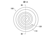
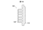
- FIG. 1A is a top view of a fixed scroll 100 that is the subject of the manufacturing process for the casting mold according to the first embodiment.
- FIG. 1B is a cross-sectional view taken along the IB-IB section line shown in FIG. 1A. Note that, for ease of understanding, FIGS. 1A and 1B show the fixed scroll 100 with the teeth facing upward.
- the fixed scroll 100 includes a base plate 110 and a scroll body 120 supported by the base plate 110.
- the shell of the scroll compressor is formed in a cylindrical shape.
- the base plate 110 is formed in a disk shape as shown in Figures 1A and 1B so that it can be fitted into the shell.
- a scroll 120 is provided on one side of the center of the base plate 110, i.e., on the top side.
- the scroll 120 has a shape in which a strip-shaped plate is bent into a spiral shape.
- the scroll 120 protrudes from the upper surface of the base plate 110 with the width direction of the plate, i.e., the extension direction of the teeth, perpendicular to the base plate 110.
- the shape of the scroll 120 allows the fixed scroll 100 to mesh with the teeth of the oscillating scroll.
- the fixed scroll 100 is incorporated into a scroll compressor (not shown), and compresses the fluid by the oscillation of the oscillating scroll while meshing with the teeth of the oscillating scroll. Next, the configuration of the oscillating scroll will be explained.
- FIG. 2A is a top view of the oscillating scroll 200 from which the mold according to the first embodiment is manufactured.
- FIG. 2B is a cross-sectional view taken along the IIB-IIB section line shown in FIG. 2A. Note that, for ease of understanding, FIGS. 2A and 2B show the oscillating scroll 200 with the teeth facing upward, as in the case of the fixed scroll 100.
- the oscillating scroll 200 includes a base plate 210, a spiral body 220 supported by the base plate 210, and a cylindrical portion 230 provided on the surface of the base plate 210 opposite the surface on which the spiral body 220 is located.
- the base plate 210 is formed in the shape of a disk with an outer diameter smaller than that of the base plate 110 of the fixed scroll 100 so that the oscillating scroll 200 can oscillate within the cylindrical shell (not shown) without interfering with the shell.
- a scroll 220 is provided on one side of the base plate 210, i.e., the top side.
- the spiral body 220 has a shape in which a strip-shaped plate is bent into a spiral shape.
- the direction in which the strip-shaped plate of the spiral body 220 spirals is the opposite direction to the spiral body 120 when viewed from above.
- the spiral body 220 protrudes from the upper surface of the base plate 210 with the width direction of the plate, i.e., the extension direction of the teeth, perpendicular to the base plate 210. Since the spiral body 220 has such a shape, the oscillating scroll 200 can mesh with the teeth of the spiral body 120 of the fixed scroll 100.
- the oscillating scroll 200 is incorporated into a scroll compressor (not shown), and oscillates to compress the fluid by meshing with the teeth of the spiral body 120 of the fixed scroll 100.
- a cylindrical portion 230 is provided on the other surface of the base plate 210, i.e., the lower surface side.
- the cylindrical portion 230 is formed with an inner diameter that allows the insertion of a crankshaft provided in a scroll compressor (not shown). When assembled in a scroll compressor, the crankshaft is inserted into the cylindrical portion 230 and connected to the crankshaft. This allows the rotation of the crankshaft to be transmitted to the cylindrical portion 230 when assembled in the scroll compressor. As a result, the cylindrical portion 230 causes the oscillating scroll 200 to oscillate.
- the fixed scroll 100 and the oscillating scroll 200 configured as described above are manufactured by casting.
- a sand mold is used that has a space, i.e., a cavity, for forming the fixed scroll 100 or the oscillating scroll 200.
- Molten metal is poured into the cavity, and the fixed scroll 100 or the oscillating scroll 200 is manufactured by allowing the molten metal to solidify.
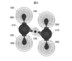
- Figure 3 is a diagram showing a simulation of the solidification state of the molten metal when casting is performed in a normal mold in which a feeder portion is arranged between the fixed scrolls 100 to be cast. Note that Figure 3 omits the illustration of the upper and lower mold halves, and shows only the molten metal 300 and the solidified molten metal.
- the outer periphery of the fixed scroll 100 solidifies first, leaving the molten metal 300 in the center of the fixed scroll 100.
- the molten metal 300 is then interrupted between the fixed scroll 100 and the feeder portion 310.
- the last solidified portion remains inside the fixed scroll 100, and shrinkage cavities occur in that portion.
- shrinkage cavities occur in the center portion of the base plate 110 where the scroll body 120 is located, the base portion of the scroll body 120, and the like.
- the scroll 220 when casting the orbiting scroll 200, the scroll 220 is provided in the center of the base plate 210, and as a result, just like in the case of the fixed scroll 100, the molten metal 300 that forms the outer periphery of the base plate 210 tends to solidify before the molten metal 300 that forms the center of the base plate 210. As a result, shrinkage cavities may occur in the center of the base plate 210. In that case, even the orbiting scroll 200 will not be able to achieve high strength.
- the casting process for casting the fixed scroll 100 or the orbiting scroll 200 uses a sand mold according to embodiment 1 that has a riser portion that is an improvement over the riser portion 310 found in a normal sand mold. That is, in embodiment 1, a sand mold is used that has a riser portion that covers the weir and the end of the cavity connected to the weir from above, and heats the weir and the end of the cavity.
- a riser refers to the supply of molten metal to prevent shrinkage or the formation of gaps in the mold cavity as the molten metal 300 solidifies, or to a pool of molten metal, but in this specification, the riser portion refers to the space that forms the latter pool of molten metal.
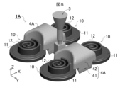
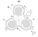
- FIG. 4 is a perspective view of the sand mold 1A according to the first embodiment.
- FIG. 5 is a perspective view showing the positional relationship between the cavity 10, the feeder portion 4A, and the sprue 5 of the sand mold 1A.
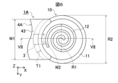
- FIG. 6 is an enlarged top view showing the positional relationship between the cavity 10 and the feeder portion 4A.
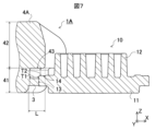
- FIG. 7 is a cross-sectional view taken along the VII-VII cutting line shown in FIG. 6.
- Fig. 4 omits the illustration of the upper and lower dies for forming the feeder portion 4A and the gate 5 of the sand mold 1A. Also, Figs. 5 to 7 omit the illustration of the upper and lower dies, as well as the core 2. Instead, Figs. 5 to 7 show the shape of the cavity 10 for casting the fixed scroll 100.
- the sand mold 1A includes a core 2 shown in FIG. 4 that forms a cavity 10, a gate 3 shown in FIG. 7 that allows molten metal 300 to flow into the cavity 10, and a riser portion 4A shown in FIG. 4 for supplying molten metal 300 to the cavity 10.
- the core 2 shown in FIG. 4 is formed from sand such as mountain sand, river sand, beach sand, synthetic sand, etc.
- the lower part of the core 2, although not shown in FIG. 4, is formed in a shape that resembles the outer shape of the upper surface of the spiral body 120 of the fixed scroll 100 described above and the outer shape of the upper surface of the base plate 110.
- the core 2 is placed between an upper mold (not shown) and a lower mold that resembles the outer shape of the lower surface of the base plate 110 described above that the fixed scroll 100 is provided with.
- the core 2, together with the upper and lower molds, forms the cavity 10 shown in FIGS. 5-7 for casting the fixed scroll 100.
- the cavity 10 has a base plate forming section 11 that forms the base plate 110 of the fixed scroll 100, and a spiral body forming section 12 that forms the spiral body 120.
- the base plate forming section 11 is connected to a dam 3 shown in Figure 7 for introducing molten metal 300 during casting.
- the base plate forming portion 11 has an end surface portion 13 that forms the outer peripheral surface of the base plate 110 of the fixed scroll 100, i.e., that forms the outer peripheral end surface.
- the dam 3 is provided adjacent to the end surface portion 13 from the outside of the cavity 10.
- the base plate forming portion 11 is a disk-shaped space, and the dam 3 communicates with that space in the diameter direction of the base plate forming portion 11 and from the outside.
- the weir 3 is the entrance to the cavity 10 through which the molten metal 300 flows into the cavity 10 during casting.
- the weir 3 is a part that is removed from the cast fixed scroll 100 after casting.
- the weir 3 is formed to be significantly smaller than the base plate 110 of the fixed scroll 100 to facilitate removal after casting.
- the shape of the weir 3 in top view, as shown in FIG. 6, is a bent rectangle having two long sides that protrude in an arc shape toward the outside of the base plate forming portion 11 and short sides that are parallel to each other.
- the long sides are smaller than the radius of the base plate forming portion 11 or the scroll diameter R1 of the scroll forming portion 12.
- the short sides are the same thickness as the wall thickness T1 of the core 2. For example, the short sides are about 3 to 15 mm.
- the cross-sectional shape of the weir 3 is rectangular as shown in FIG. 7. Its length, i.e., the length in the X direction, is the same as the wall thickness T1 of the core 2 described above.
- the height of the weir 3 in cross-sectional view, i.e., the length in the Z direction, is equal to or less than the Z direction length of the end face portion 13 of the base plate forming portion 11. For example, the length in the Z direction is 3 to 60 mm.
- the supply portion 41 of the feeder portion 4A is adjacent to the side of the weir 3 opposite to the side adjacent to the base plate forming portion 11, i.e., the -X side of the weir 3. This connects the weir 3 to the feeder portion 4A.
- the feeder section 4A functions as a molten metal reservoir that supplies the molten metal 300 to the cavity 10.
- the feeder section 4A is equipped with a supply section 41 that is connected to the weir 3 to supply the molten metal 300, and a heating section 42 that has a portion facing the weir 3 and the end of the base plate forming section 11 that is connected to the weir 3, and heats the weir 3 and the end of the base plate forming section 11 when the molten metal 300 is poured in.
- the supply section 41 is connected to the weir 3 and functions as a connection section for the feeder section 4A.
- the supply section 41 is formed in a rectangular shape with two long sides concave inward in an arc shape when viewed from above. This is because, as shown in FIG. 5, the supply section 41 is adjacent to the base plate forming section 11 between the base plate forming sections 11 of the cavity 10, and these base plate forming sections 11 are circular when viewed from above. As shown in FIG. 7, the supply section 41 extends to a position higher than the base plate forming section 11 of the cavity 10 while maintaining its shape when viewed from above.
- the supply section 41 is connected to the weir 3 described above midway. As a result, when the molten metal 300 is poured during casting, the supply section 41 supplies the molten metal 300 to the base plate forming section 11.
- the heating section 42 extends from the supply section 41 to a position higher than the spiral body forming section 12 of the cavity 10, making it possible to supply the molten metal 300 to the spiral body forming section 12 during casting. Furthermore, the heating section 42 protrudes from the supply section 41 above the outer periphery of the weir 3 and the base plate forming section 11, and heats the outer periphery of the weir 3 and the base plate forming section 11 with the heat of the molten metal 300 during casting.
- the heating section 42 is provided above the supply section 41, and extends from the upper end of the supply section 41 to a position sufficiently higher than the spiral body forming section 12 of the cavity 10.
- the upper end of the heating section 42 is 10 mm or more higher than the spiral body forming section 12. This allows the heating section 42 to flow the molten metal 300 into the supply section 41 during casting, and to replenish the molten metal 300 to the entire cavity 10, including the spiral body forming section 12.
- the heating section 42 also protrudes from the supply section 41 towards the cavity 10. That is, the heating section 42 protrudes from the supply section 41 towards the +X side. Furthermore, the position from which the heating section 42 protrudes is a position spaced upward from the outer periphery of the base plate forming section 11 of the cavity 10. As a result, the heating section 42 covers the outer periphery of the base plate forming section 11 from above. In other words, the heating section 42 overlaps with the outer periphery of the base plate forming section 11 when viewed from a direction perpendicular to the plate surface of the base plate forming section 11, that is, when viewed from above or below.
- the heating section 42 is formed by the outer surface of the core 2 (not shown in FIG. 7 ), and therefore protrudes upward from the base plate forming section 11 by the thickness T2 of the core 2. That is, the heating section 42 protrudes from a position on the +Z side of the base plate forming section 11, which is separated from the base plate forming section 11 by the thickness T2 of the core 2.
- the heating section 42 also protrudes from the supply section 41 toward the +X side by a distance L greater than the thickness T1 of the core 2. That is, the heating section 42 protrudes toward the +X side by a distance greater than the X-direction length of the weir 3.
- the heating section 42 protrudes, for example, from the spiral body forming section 12 to a position separated by the thickness T1 of the core 2 in the -X direction. This causes the heating section 42 to face the weir 3.
- the heating section 42 also faces the -X end of the top surface section 14 of the base plate forming section 11.
- the heating portion 42 has a facing portion 43 that faces the weir 3 and the ⁇ X end portion of the top surface portion 14 .
- the thickness T1 of the core 2 in the X direction may be different from the thickness T2 of the core 2 in the Z direction, or may be the same as the thickness T2.
- the width W1 of the facing portion 43 in top view is equal to or greater than the width W2 of the weir 3.
- the width W2 of the weir 3 is 10-20% of the scroll diameter R1
- the minimum value of the width W1 of the facing portion 43 is 10-20% of the scroll diameter R1.
- the minimum value of the width W1 of the facing portion 43 is 50 mm smaller than the scroll diameter R1.
- the maximum value of the width W1 of the facing portion 43 is 50 mm larger than the diameter R2 of the base plate forming portion 11.
- the facing portion 43 has this width W1 and protrudes the above-mentioned distance L, thereby completely covering the weir 3 from above.
- the facing portion 43 faces the weir 3 or the -X end of the top surface 14 of the base plate forming portion 11 at a distance equal to the thickness T2 of the core 2. This is because the facing portion 43 is formed by the outer surface of the core 2.
- the heating portion 42 transfers the heat of the molten metal 300 from the facing portion 43 through the core 2 to the weir 3 and the -X end of the top surface 14 of the base plate forming portion 11.
- the heating portion 42 heats the weir 3 and the -X end of the top surface 14 of the base plate forming portion 11 during casting.
- the sand mold 1A makes the molten metal 300 at the weir 3 and the molten metal 300 flowing under the top surface 14 of the base plate forming portion 11 less likely to solidify than the molten metal 300 in other parts during casting.
- the molten metal 300 can be replenished from the feeder portion 4A until all of the molten metal 300 that has flowed into the cavity 10 solidifies, preventing the occurrence of shrinkage cavities inside the cavity 10. This allows the sand mold 1A to cast a fixed scroll 100 with sufficient strength.
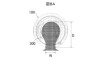
- FIG. 8A is a simulation diagram showing the solidification of molten metal 300 after a certain time has elapsed since molten metal 300 was poured into a normal sand mold when fixed scroll 100 is cast using the normal sand mold.
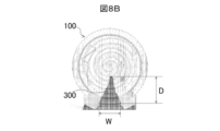
- FIG. 8B is a simulation diagram showing the solidification of molten metal 300 after a certain time has elapsed since molten metal 300 was poured into sand mold 1A when fixed scroll 100 is cast using sand mold 1A according to embodiment 1.
- the sand mold 1A according to the first embodiment has a smaller depth D relative to the width W of the molten metal 300 than a normal sand mold. Specific values are shown in Table 1.
- the depth D relative to the width W of the molten metal 300 is less than half that of a normal sand mold. This shows that in the sand mold 1A, the molten metal 300 forming the outer periphery of the fixed scroll 100 is less likely to solidify before the molten metal 300 forming the central portion. As a result, in the sand mold 1A, the molten metal 300 forming the outer periphery of the fixed scroll 100 is less likely to solidify first, and the molten metal 300 forming the central portion of the fixed scroll 100 is less likely to become isolated. In this way, in the sand mold 1A, the molten metal 300 forming the central portion of the fixed scroll 100 is less likely to become isolated and shrinkage cavities are less likely to occur than in a normal sand mold.
- the sand mold 1A described above is an example of a casting mold as defined in the present disclosure.
- the upper and lower molds are an example of a main mold as defined in the present disclosure.
- the supply section 41 of the feeder section 4A is an example of a connection section as defined in the present disclosure.
- the heating section 42 or the opposing section 43 of the feeder section 4A is an example of an opposing section as defined in the present disclosure.
- the end surface section 13 is an example of a first surface section as defined in the present disclosure.
- the top surface section 14 of the base plate forming section 11 is an example of a second surface section as defined in the present disclosure.
- the fixed scroll 100 described above is an example of a member having a plate-like portion and a protruding portion protruding from one of the plate surfaces of the plate-like portion as defined in this disclosure.
- the base plate 110 and the scroll body 120 of the fixed scroll 100 are an example of a plate-like portion and a protruding portion as defined in this disclosure.
- the sand mold 1A may be used to cast the oscillating scroll 200.
- the oscillating scroll 200 is an example of a member having the above-mentioned plate-shaped portion and a protruding portion protruding from one plate surface of the plate-shaped portion.
- the base plate 210 of the oscillating scroll 200 is also an example of the above-mentioned plate-shaped portion.
- the scroll body 220 and cylindrical portion 230 of the oscillating scroll 200 are examples of the above-mentioned protruding portion.
- the fixed scroll 100 and the oscillating scroll 200 described above are manufactured by (1) a casting process in which molten metal is poured into a sand mold 1A and solidified, and (2) a post-processing process after the casting process in which the sand mold 1A is disassembled, the sand is removed, and burrs and other parts where the molten metal has solidified at the gate 3, the riser portion 4A, etc. are removed from the cast fixed scroll 100 or the oscillating scroll 200.
- the above-mentioned casting process is an example of the casting process referred to in this disclosure.
- the feeder section 4A has a heating section 42 that covers the weir 3 and the end of the top surface section 14 of the base plate forming section 11 adjacent to the weir 3 from the supply section 41, and warms the weir 3 and the end of the top surface section 14 with the heat of the molten metal when the molten metal flows in. Therefore, in the sand mold 1A, the molten metal 300 in the weir 3 and the molten metal 300 flowing through the top surface section 14 are unlikely to solidify.
- the sand mold 1A can supply the molten metal 300 from the feeder section 4A via the weir 3 and the top surface section 14 until all of the molten metal 300 inside the cavity 10 solidifies. As a result, the sand mold 1A can prevent the occurrence of shrinkage cavities in the fixed scroll 100. This allows the sand mold 1A to cast a fixed scroll 100 with high strength.
- the construction of the sand mold 1A is simple, as it is sufficient that the riser portion 4A covers the ends of the weir 3 and the top surface portion 14 of the base plate forming portion 11 and faces the ends of the weir 3 and the top surface portion 14. As a result, the sand mold 1A is easy to manufacture.
- the sand mold 1A has four cavities 10, but the configuration including each of the cavities 10, the weirs 3 connected to each of the cavities 10, and the feeder portions 4A connected to each of the cavities 10 may be called a casting mold or sand mold. In that case, in the first embodiment, the combination of these four casting molds or sand molds may be called a casting mold system.
- the sand mold 1A has four cavities 10 and two feeder portions 4A in order to cast four fixed scrolls 100.
- the sand mold 1A is not limited to this.
- the feeder portion 4A has heating portions 42 corresponding to each of the plurality of cavities 10.
- one riser portion 4B is provided for each of the three cavities 10.
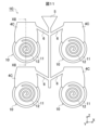
- FIG. 9 is a top view of sand mold 1B according to embodiment 2. Note that the upper and lower molds and core 2 are omitted from FIG. 9 for ease of understanding.
- the sand mold 1B has three cavities 10 and one feeder portion 4B connected to the three cavities 10.
- Each of the cavities 10 is formed to have the same shape and size as the cavity 10 described in embodiment 1.
- the cavities 10 are arranged at a fixed distance from the center C, at 120° intervals clockwise around the center C shown in FIG. 9.
- a weir 3 is adjacent to each of the cavities 10, in the same relative positional relationship as described in embodiment 1.
- each of the weirs 3 is connected to a supply section 41 (not shown in FIG. 9) of the feeder section 4B.
- the feeder 4B has the same number of opposing parts 43 of the heating section 42 as the cavities 10, that is, three, as described in the first embodiment, although not shown in FIG. 9.
- Each opposing part 43 faces the dam 3 in the same relative positional relationship as described in the first embodiment.
- each opposing part 43 faces the end of the top surface 14 of the base plate forming part 11, which is not shown in FIG. 9, provided in each cavity 10.
- the feeder portion 4B is provided with the opposing portion 43 of the heating portion 42 for each cavity 10, similar to the first embodiment. Therefore, in the sand mold 1B, like the first embodiment, it is possible to prevent the occurrence of shrinkage cavities in the fixed scroll 100. As a result, the sand mold 1B can cast a fixed scroll 100 with high strength.
- sand mold 1B is an example of a mold as defined in this disclosure. Or, it is an example of a mold system.
- the above-mentioned feeder 4B has a relatively large shape covering the outer periphery of each cavity 10 from the center C.
- the feeder 4B may be provided with a cylindrical through-portion 44 as shown in Figure 9.
- the through-portion 44 may be cylindrical or may be prismatic, for example triangular.
- the shape of the feeder portion 4B when viewed from above may be an arc shape that follows the outer periphery of the base plate forming portion 11 of each cavity 10, and in this case, the arc shape may cover the outer periphery of the base plate forming portion 11.
- the space between the cavities 10 may be either linear or curved.
- the feeder 4B is connected to one gate 5 by one runner 6.
- the relationship between the feeder 4B and the gate 5 is not limited to this.
- the feeder 4B may be connected to one gate 5 by a plurality of runners 6.
- FIG. 10 is a top view of a modified sand mold 1B according to embodiment 2. As with FIG. 9, the upper and lower molds and the core 2 are omitted in FIG. 10 for ease of understanding.
- the sand mold 1B may have six cavities 10.
- each of the cavities 10 may be arranged at a certain distance from the center C, at 60° intervals clockwise around the center C.
- the feeder 4B may have an annular shape in which the center of a hexagon is hollowed out in a hexagonal shape with each side recessed inward in an arc shape when viewed from above.
- the gate 5 may be arranged in the center of the internal space of the annular feeder 4B when viewed from above.
- a runner 6 may extend from each of the cavities 10. More specifically, a total of six runners 6 may extend toward the gate 5 from each of six locations of the supply section 41 of the feeder 4B adjacent to the weir 3 connected to each of the cavities 10. This is because even in this form, the sand mold 1B can pour the molten metal 300 into the six cavities 10 from one gate 5.
- the feeder parts 4A, 4B cover the weir 3 and the end of the top surface part 14 of the base plate forming part 11 of the cavity 10 from above.
- the feeder parts 4A, 4B are not limited to this.
- the feeder sections 4A and 4B may have a supply section 41 connected to the weir 3 and supplying the molten metal 300 to the weir 3, and a heating section 42 that is located at a position separated from the weir 3 and the end of the top surface section 14 of the base plate forming section 11 adjacent to the weir 3 in a direction perpendicular to the top surface section 14 and overlaps the weir 3 and the end of the top surface section 14 when viewed from a direction perpendicular to the top surface section 14, and that heats the weir 3 and the end of the top surface section 14 with the heat of the molten metal 300 when the molten metal 300 flows in. Therefore, in the feeder sections 4A and 4B, the opposing portion 43 provided in the heating section 42 does not have to cover the weir 3 and the end of the top surface section 14 from above.
- the sand mold 1C according to embodiment 3 has a facing portion 45 where the riser portion 4C covers the ends of the weir 3 and the top surface portion 14 from the front.
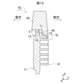
- FIG. 11 is a front view of a sand mold 1C according to embodiment 3.
- FIG. 12 is a cross-sectional view taken along the line XII-XII shown in FIG. 11.
- the sand mold 1C has four cavities 10. In each cavity 10, the plate surface of the base plate forming portion 11 of the cavity 10 faces in the front-to-rear direction. A riser portion 4C is provided on the base plate forming portion 11.
- the feeder section 4C is provided above the weir 3 provided at the upper end of the base plate forming section 11.
- the bottom surface of the feeder section 4C extends from above the weir 3 to the front F, and then bends downward.
- the bottom surface of the feeder section 4C is lowered to a position spaced apart from the spiral body forming section 12 of the cavity 10 by the thickness T3 of the core 2.
- the bottom surface of the feeder section 4C covers the upper end of the weir 3 and the top surface section 14 of the base plate forming section 11 from the front F.
- the bottom surface of the feeder section 4C has an opposing portion 45 that faces the weir 3 and the upper end of the top surface section 14.
- the wall thickness T3 of the core 2 adjacent to the spiral body forming portion 12 may be different from or the same as the wall thicknesses T1 and T2 described in the first embodiment.
- the relative positional relationship of the facing portion 45 to the weir 3 and the upper end of the top surface portion 14 is the same as the relative positional relationship of the facing portion 43 described in embodiment 1 to the end of the weir 3 and the top surface portion 14, except that the orientation of the facing portion 45 is different.
- the feeder portion 4C transfers the heat of the molten metal 300 from the facing portion 45 through the core 2 to the weir 3 and the upper end of the top surface portion 14 of the base plate forming portion 11.
- the sand mold 1C As a result, in the sand mold 1C, the molten metal 300 in the weir 3 and the molten metal 300 flowing along the top surface portion 14 of the base plate forming portion 11 during casting is less likely to solidify than the molten metal 300 in other parts. As a result, the sand mold 1C can be replenished with molten metal 300 from the feeder portion 4C until all of the molten metal 300 solidifies. This allows the sand mold 1C to prevent shrinkage cavities from occurring inside the cavity 10 and cast a fixed scroll 100 with sufficient strength.
- the facing portion 45 of the feeder portion 4C can heat the weir 3 and the end of the top surface portion 14 of the base plate forming portion 11 with the heat of the molten metal 300 during casting, thereby improving heat retention.
- the sand mold 1C can prevent the occurrence of shrinkage cavities in the fixed scroll 100 and cast a fixed scroll 100 with high strength.
- sand mold 1C is an example of a mold as defined in this disclosure. Or, it is an example of a mold system.
- the feeder sections 4A, 4B may include a supply section 41 connected to the weir 3 and supplying molten metal 300 to the weir 3, and a heating section 42 located at a position separated from the weir 3 and the end of the top surface section 14 of the base plate forming section 11 adjacent to the weir 3 in a direction perpendicular to the top surface section 14, and located at a position overlapping the weir 3 and the end of the top surface section 14 when viewed from the direction perpendicular to the top surface section 14, and which warms the weir 3 and the end of the top surface section 14 with the heat of the molten metal 300 when the molten metal 300 flows in.
- the sand mold 1D according to embodiment 4 has a riser portion 4D that is below the ends of the dam 3 and the top surface portion 14 and has an opposing portion 43 that faces the ends of the dam 3 and the top surface portion 14.
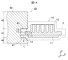
- FIG. 13 is a cross-sectional view of a sand mold 1D according to embodiment 4. Note that FIG. 13 shows a cross-sectional view taken along a cut line that cuts the same location as the VII-VII cut line shown in FIG. 6.
- the cavity 10 of the sand mold 1D according to embodiment 4 is arranged vertically symmetrically to the cavity 10 described in embodiment 1.
- the base plate forming part 11 is arranged on the upper side, and the spiral body forming part 12 is arranged on the lower side.
- the top surface part 14 and the bottom surface part 15 of the base plate forming part 11 extend toward the outer periphery, and the weir 3 is connected to the end of the extension.
- the weir 3 is formed to have the same shape and size as described in the first embodiment. As a result, the weir 3 extends horizontally from the outer periphery of the base plate forming part 11, specifically in the X direction. The weir 3 is connected to the supply part 41 of the feeder part 4D described in the first embodiment at its end.
- a heating section 42 is disposed below the supply section 41.
- the supply section 41 is provided in the horizontal direction of the weir 3 and the base plate forming section 11 of the cavity 10. Furthermore, the heating section 42 is provided below the weir 3 and the base plate forming section 11 by the thickness T2 of the core 2.
- the heating section 42 protrudes from the supply section 41 toward the side where the spiral body forming section 12 of the cavity 10 is located, i.e., toward the +X side.
- the shape of the heating section 42 is a trapezoid whose upper and lower sides extend in the X direction when viewed in an XZ cross section.
- the protruding length of the heating section 42 is such that the +X end of the heating section 42 reaches a position that is away from the spiral body forming section 12 of the cavity 10 by the thickness T2 of the core 2.
- the +Z surface of the heating section 42 is horizontal and faces the weir 3 and the top surface 14 of the base plate forming section 11.
- the heating section 42 has an opposing portion 43.
- the feeder section 4D warms the ends of the weir 3 and the top surface 14 of the base plate forming section 11 with the heat of the molten metal 300, as in the case described in embodiment 1-3. For this reason, even with the sand mold 1D, shrinkage cavities are unlikely to occur in each of the cavities 10. As a result, even with the sand mold 1D, a fixed scroll 100 with high strength can be cast.
- the cavity 10 is vertically symmetrical to that in the first embodiment.
- the spiral body forming portion 12 is disposed below the base plate forming portion 11, and the top surface portion 14 of the base plate forming portion 11 faces downward.
- the top surface portion 14 extends horizontally.
- the feeder portion 4D protrudes below the dam 3 and the base plate forming portion 11. Therefore, in the sand mold 1D according to the fourth embodiment, as in the first embodiment, the feeder portion 4D can heat the ends of the dam 3 and the top surface portion 14 of the base plate forming portion 11 with the heat of the molten metal 300 during casting, thereby improving heat retention.
- the sand mold 1D can cast a fixed scroll 100 with high strength by preventing the occurrence of shrinkage cavities in the fixed scroll 100.
- the heating unit 42 may be disposed not only below the supply unit 41 but also above the supply unit 41.
- the spiral body forming unit 12 may be disposed above the base plate forming unit 11, as in the first embodiment.
- FIG. 14 is a cross-sectional view of a modified example of sand mold 1D according to embodiment 4. Note that, like FIG. 13, FIG. 14 shows a cross-sectional view taken along a cut line that cuts the same location as cut line VII-VII shown in FIG. 6.
- the sand mold 1D may have a cavity 10 in which the spiral body forming part 12 is disposed above the base plate forming part 11.
- the top surface part 14 of the base plate forming part 11 may be facing upward.
- the feeder part 4D may have a heating part 42 provided above the supply part 41, as in the first embodiment, and a heating part 46 provided below the supply part 41, as in the fourth embodiment.
- the heating section 42 protrudes in the +X direction from the supply section 41, so that the heating section 42 has an opposing portion 43 that faces the ends of the top surface 14 of the base plate forming section 11 of the weir 3 and the cavity 10.
- the heating section 46 protrudes in the +X direction from the supply section 41, so that the heating section 46 has an opposing portion 47 that faces the ends of the bottom surface 15 of the base plate forming section 11 of the weir 3 and the cavity 10. This is because, with such a configuration, the heating sections 42 and 46 can heat the weir 3 and the ends of the top surface 14 of the base plate forming section 11 from above and below with the heat of the molten metal 300 during casting, thereby improving heat retention.
- the heating unit 46 is an example of a second heating unit as defined in this disclosure.
- the sand mold 1D is an example of a casting mold as defined in this disclosure.
- sand mold 1A-1D has multiple cavities 10 and is capable of casting multiple fixed scrolls 100, but sand mold 1A-1D is not limited to this.
- Sand mold 1A-1D only needs to have at least one cavity 10. And it only needs to be capable of casting the same number of fixed scrolls 100 as there are cavities 10.
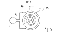
- FIG. 15 is a top view of a modified sand mold 1A according to embodiment 1. Note that the directions of the X-axis, Y-axis, and Z-axis in the orthogonal coordinate system XYZ shown in FIG. 15 are the same as those in the orthogonal coordinate system XYZ shown in FIG. 4 to FIG. 7. The same also applies to FIG. 16 and FIG. 17 described later.
- the sand mold 1A may have one cavity 10 and one riser 4A. Naturally, this configuration also makes it possible to prevent shrinkage cavities from occurring and produce a fixed scroll 100 with high strength.
- sand molds 1A-1D have only one dam 3 for each cavity 10, but the number of dams 3 is arbitrary as long as the positional relationship with the opposing parts 43, 45 of feeder sections 4A-4D is maintained.
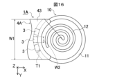
- FIG. 16 is a top view of another modified example of sand mold 1A according to embodiment 1.
- the sand mold 1A may have three dams 3.
- the sand molds 1A-1D may have multiple dams 3. Even in this form, as long as the positional relationship between the opposing parts 43, 45 of the feeder sections 4A-4D is maintained, it is possible to prevent the occurrence of shrinkage cavities and manufacture a fixed scroll 100 with high strength. In this case, it is preferable that the width W2 of the dams 3 is small so that they can be easily removed after casting.
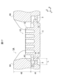
- FIG. 17 is a top view of yet another modified example of sand mold 1A according to embodiment 1.
- the sand mold 1A may have two weirs 3.
- each weir 3 is provided on the outer periphery of the disk-shaped base plate forming portion 11 of the cavity 10, and the two weirs 3 face each other across the center of the base plate forming portion 11.
- the same number of feeder portions 4A as the number of weirs 3 may be provided, and the heating portion 42 of each feeder portion 4A may face the weir 3 and the end of the base plate forming portion 11 connected to that weir 3. This is because, with this configuration, the occurrence of shrinkage cavities can be prevented with each weir 3.
- the facing parts 43, 45, 47 are arranged parallel to the weir 3 and face each other. Furthermore, the facing parts 43, 45, 47 are arranged parallel to the end of the top surface portion 14 and face each other. However, the facing parts 43, 45, 47 are not limited to this.
- the feeder parts 4A-4D are provided at a position separated from the weir 3 and the end of the top surface portion 14 of the base plate forming part 11 adjacent to the weir 3 in a direction perpendicular to the top surface portion 14, and are provided at a position overlapping the weir 3 and the end of the top surface portion 14 when viewed from a direction perpendicular to the top surface portion 14, and have a heating part 42 that warms the weir 3 and the end of the top surface portion 14 with the heat of the molten metal 300 when the molten metal 300 flows in. Therefore, the facing parts 43, 45, 47 do not have to be parallel to the weir 3 and the end of the top surface portion 14.
- the facing portions 43, 45, 47 may be inclined with respect to the ends of the dam 3 and the top surface portion 14.
- the facing portions 43, 45, 47 may be inclined so that the distance between the dam 3 or the top surface portion 14 increases as the distance from the dam 3 increases toward the side where the top surface portion 14 is located. With such an inclination, the closer the portion is to the dam 3, the warmer it becomes during casting, which can prevent the occurrence of shrinkage cavities.
- the facing portions 43, 45, 47 do not need to be flat, and may be uneven or curved.
- sand mold 1A-1D casts fixed scroll 100, i.e., a scroll member.
- the casting object of sand mold 1A-1D is not limited to this.
- Sand mold 1A-1D may be any casting mold that casts a member having a plate-shaped portion and a protruding portion that protrudes from one of the plate surfaces of the plate-shaped portion. Therefore, sand mold 1A-1D may be any casting mold that casts a member that satisfies this condition.
- FIG. 18 is a perspective view of a heat sink 7 that is the subject of sand mold manufacturing in another embodiment.
- the heat sink 7 comprises a support plate 71 and a plurality of pin-shaped fins 72 arranged in a matrix.
- the heat sink 7 may be cast by applying the sand mold 1A-1D.
- the support plate 71 is cast by applying the base plate forming portion 11 of the cavity 10 provided in the sand mold 1A-1D, and the spiral body forming portion 12 of the cavity 10 is replaced with a fin forming portion to cast the plurality of fins 72.
- Fins 72 may be formed in a pin shape, or in a flat, corrugated, arc-shaped, or quadratically curved plate shape, with the end faces of the plate supported by support plate 71.
- fins 72 When fins 72 are flat or corrugated, fins 72 may be arranged parallel to each other.
- each fin 72 may be arranged so that its surface extends radially from the center of the surface of support plate 71.
- the mold, mold system, and method of manufacturing the component are not limited to the above-described embodiments, and various modifications and substitutions can be made thereto.
- Various aspects of the present disclosure are described below as appendices.
- the member is a fixed scroll or a swing scroll of a scroll compressor,
- the plate-shaped portion is a base plate provided in the fixed scroll or the orbiting scroll,
- the protruding portion is a spiral body provided on the fixed scroll or the orbiting scroll and protruding from one plate surface of the base plate.
- the member is a heat sink, the plate-shaped portion is a support plate included in the heat sink,
- the protrusion is a fin provided on the heat sink, supported by the support plate, and protruding from one plate surface of the support plate.
- a plurality of molds each for casting a member having a plate-shaped portion and a protruding portion protruding from one plate surface of the plate-shaped portion, a cavity including a first surface portion for forming an end surface of the plate-shaped portion and a second surface portion for forming either one of the plate surfaces of the plate-shaped portion and the other plate surface, the cavity into which molten metal flows and into which the plate-shaped portion and the protrusion are cast when the molten metal solidifies; a weir provided adjacent to the first surface portion from the outside of the cavity for allowing the molten metal to flow into the cavity; a feeder section including a supply section connected to the weir and supplying the molten metal to the weir, and a heating section provided at a position spaced from the weir and an end of the second surface section adjacent to the weir in a direction perpendicular to the second surface section and overlapping the weir and the end of the second surface section when viewed in the direction
Landscapes
- Engineering & Computer Science (AREA)
- Mechanical Engineering (AREA)
- Molds, Cores, And Manufacturing Methods Thereof (AREA)
Abstract
鋳型は、板状部の端面を形成するための第1面部と板状部の一方の板面と他方の板面のいずれか一方の板面を形成するための第2面部とを含み、溶湯が流入し、かつ溶湯が凝固した場合に板状部と突出部とを鋳造するキャビティ(10)と、キャビティ(10)の外側から第1面部に隣接して設けられ、溶湯をキャビティ(10)に流入させるための堰(3)と、堰(3)に接続され、溶湯を堰(3)に供給する供給部(41)と、堰(3)と堰(3)に隣接する第2面部の端部とから第2面部と垂直な方向に隔てられた位置に設けられると共に、堰(3)と第2面部の端部とに第2面部と垂直な方向から視て重なり合う位置に設けられ、溶湯が流入した場合に溶湯の熱で堰(3)と第2面部の端部を温める加温部(42)と、を有する押湯部(4A)と、を備える。
Description
本開示は鋳型、鋳型システムおよび部材の製造方法に関する。
板状部とその板状部の一方の板面から突出する突出部とを有する部材には、例えば、スクロール圧縮機に用いられる固定スクロールまたは揺動スクロールがある。このような部材は、鋳造により製造されることがあり、その場合の鋳造時の欠陥の発生、例えば、引け巣の発生を防ぐため、様々な鋳型が開発されている。
例えば、特許文献1には、揺動スクロールが備える台板の中央部分に薄肉部分を形成する半溶融成形用の金型が開示されている。特許文献1に記載の金型は、台板を形成する部分に凸部を設けることにより、台板の中央部分に薄肉部分を形成する。これにより、この金型は、半溶融成の金属の凝固を早めて引け巣の発生を防いでいる。
また、特許文献2には、冷却手段、例えば、水冷ジャケットが設けられた、揺動スクロールを鋳造するための金型が開示されている。特許文献2に記載の金型では、鋳造時に揺動スクロールが備える渦巻体中央部を冷却手段が強制的に冷却する。これにより、この金型は、渦巻体中央部から外周部に向けて溶湯に凝固指向性を持たせる。その結果、この金型は、引け巣の発生を防いでいる。
特許文献1に記載の金型の構造は、キャビティ内に凸部を設けるため、複雑になりやすい。また、特許文献2に記載の金型の構造も、金型内に冷却手段を設けるため、複雑になりやすい。
本開示は上記の課題を解決するためになされたもので、簡易な構成で引け巣の発生を防ぐことができる鋳型、鋳型システムおよび部材の製造方法を提供することを目的とする。
上記の目的を達成するため、本開示に係る鋳型は、板状部と板状部の一方の板面から突出する突出部とを有する部材を鋳造する鋳型である。そして、鋳型は、キャビティと、堰と、押湯部と、を備える。キャビティは、板状部の端面を形成するための第1面部と板状部の一方の板面と他方の板面のいずれか一方の板面を形成するための第2面部とを含み、溶湯が流入し、かつ溶湯が凝固した場合に板状部と突出部とを鋳造する。堰は、キャビティの外側から第1面部に隣接して設けられ、溶湯をキャビティに流入させるためのものである。押湯部は、堰に接続され、溶湯を堰に供給する供給部と、堰と堰に隣接する第2面部の端部とから第2面部と垂直な方向に隔てられた位置に設けられると共に、堰と第2面部の端部とに第2面部と垂直な方向から視て重なり合う位置に設けられ、溶湯が流入した場合に溶湯の熱で堰と第2面部の端部を温める加温部とを有する。
本開示の構成によれば、押湯部は、堰に接続され、溶湯を堰に供給する供給部と、堰と堰に隣接する第2面部の端部とから第2面部と垂直な方向に隔てられた位置に設けられると共に、堰と第2面部の端部とに第2面部と垂直な方向から視て重なり合う位置に設けられ、溶湯が流入した場合に溶湯の熱で堰と第2面部の端部を温める加温部とを有する。このため、鋳型では、堰にある溶湯と第2面部に接する溶湯が凝固しにくく、押湯部から溶湯を安定して補給することができる。その結果、鋳型は、引け巣の発生が防がれた部材を鋳造することができる。また、押湯部に、供給部と加温部を設けるだけのため、鋳型の構成が簡易である。
以下、本開示の実施の形態に係る鋳型、鋳型システムおよび部材の製造方法について図面を参照して詳細に説明する。なお、図中、同一又は同等の部分には同一の符号を付す。
(実施の形態1)
実施の形態1に係る鋳型は、スクロール圧縮機が備えるスクロール部材を鋳造するための鋳型である。この鋳型では、引け巣の発生を防ぐため、押湯部が設けられ、その押湯部が堰と堰につながるキャビティの端部とを上から被さっている。
実施の形態1に係る鋳型は、スクロール圧縮機が備えるスクロール部材を鋳造するための鋳型である。この鋳型では、引け巣の発生を防ぐため、押湯部が設けられ、その押湯部が堰と堰につながるキャビティの端部とを上から被さっている。
以下、鋳型が重力鋳造では汎用的な砂型であり、かつ鋳造対象がスクロール部材の一種の固定スクロールまたは揺動スクロールである場合を例に、鋳型の構成について詳細に説明する。まず、図1A、図1B、図2および図3を参照して、鋳造対象である固定スクロールと揺動スクロールの構成について説明する。
図1Aは、実施の形態1に係る鋳型の製造対象である固定スクロール100の上面図である。図1Bは、図1Aに示すIB-IB切断線の断面図である。なお、図1Aおよび図1Bは、理解を容易にするため、歯先を上に向けた固定スクロール100を示している。
図1Aおよび図1Bに示すように、固定スクロール100は、台板110と、台板110に支持された渦巻体120とを備える。
図示しないが、スクロール圧縮機が備えるシェルは、円筒状に形成されている。台板110は、そのシェルに嵌め込むため、図1Aおよび図1Bに示すように、円板状に形成されている。そして、台板110の中央部の一方の面、すなわち上面の側には、渦巻体120が設けられている。
渦巻体120は、帯状の板が渦巻き状に曲げられた形状を有する。そして、渦巻体120は、板の幅方向、すなわち歯の延在方向を台板110に対して垂直にした状態で、台板110の上面から突出している。固定スクロール100は、渦巻体120がこのような形状を有することにより、揺動スクロールの歯と噛み合わせ可能である。そして、固定スクロール100は、図示しないスクロール圧縮機に組み込まれ、揺動スクロールの歯と噛み合わせられた状態で、揺動スクロールの揺動によって流体を圧縮する。続いて、揺動スクロールの構成について説明する。
図2Aは、実施の形態1に係る鋳型の製造対象である揺動スクロール200の上面図である。図2Bは、図2Aに示すIIB-IIB切断線の断面図である。なお、図2Aおよび図2Bは、理解を容易にするため、固定スクロール100の場合と同様に、歯先を上に向けた揺動スクロール200を示している。
図2Aおよび図2Bに示すように、揺動スクロール200は、台板210と、台板210に支持された渦巻体220と、台板210の、渦巻体220がある面と反対側の面に設けられた円筒部230とを備える。
台板210は、上述した図示しない円筒状のシェルに干渉することなく揺動スクロール200をシェル内で揺動可能とするため、固定スクロール100の台板110よりも外径が小さい円板の形状に形成されている。そして、台板210の一方の面、すなわち上面の側には、渦巻体220が設けられている。
渦巻体220は、帯状の板が渦巻き状に曲げられた形状を有する。その渦巻体220の帯状の板が渦巻く方向は、上面視で渦巻体120と反対方向である。そして、渦巻体220は、板の幅方向、すなわち歯の延在方向を台板210に対して垂直にした状態で、台板210の上面から突出している。揺動スクロール200は、渦巻体220がこのような形状を有することにより、固定スクロール100が備える渦巻体120の歯と噛み合わせ可能である。揺動スクロール200は、図示しないスクロール圧縮機に組み込まれ、かつ固定スクロール100の渦巻体120の歯と噛み合わせられることにより、揺動して流体を圧縮する。一方、台板210の他方の面、すなわち下面の側には、円筒部230が設けられている。
円筒部230は、図示しないスクロール圧縮機が備えるクランクシャフトが差し込み可能な内径に形成されている。そして、円筒部230には、スクロール圧縮機に組み込まれたときにクランクシャフトが差し込まれてクランクシャフトに接続される。これにより、円筒部230には、スクロール圧縮機に組み込まれたときにクランクシャフトの回転が伝わる。その結果、円筒部230は、揺動スクロール200を揺動させる。
このような構成の固定スクロール100と揺動スクロール200は、鋳造により製造されている。その鋳造では、固定スクロール100または揺動スクロール200を形成するための空間、すなわちキャビティを備える砂型が用いられている。そのキャビティに溶湯が流し込まれ、その溶湯が凝固させることにより、固定スクロール100または揺動スクロール200が製造されている。
しかしながら、台板110の中央部に渦巻体120が設けられているため、固定スクロール100の鋳造時に、台板110の中央部の熱量が大きくなってしまう。その結果、渦巻体120直下にある台板110の中央部を形成する溶湯の凝固が遅くなってしまう。これにより、台板110の外周部を形成する溶湯が、台板110の中央部を形成する溶湯よりも先に凝固してしまい、その結果、台板110の中央部に引け巣が発生してしまうことがある。その引け巣の原因である、台板110の外周部が先に凝固してしまう様子を図3に示す。
図3は、鋳造対象の固定スクロール100同士の間に押湯部が配置された通常の鋳型で鋳造したときの溶湯の凝固状態をシミュレーションしたときの図である。なお、図3は、鋳型の上型、下型の図示を省略して、溶湯300と凝固した溶湯だけを示している。
図3に示すように、鋳造時では、固定スクロール100の外周部が先に凝固し、固定スクロール100の中央部に溶湯300が残存している。そして、固定スクロール100部分と押湯部310との間で溶湯300が途切れている。その結果、最終凝固部分が固定スクロール100内に残ってしまい、その部分で引け巣が発生してしまう。例えば、台板110の渦巻体120がある中央部分、渦巻体120の根元部分等に引け巣が発生してしまう。このような引け巣が発生すると、固定スクロール100では、高い強度が求められるにもかかわらず、強度が低下してしまう。
図示しないが、揺動スクロール200の鋳造時にも、台板210の中央部に渦巻体220が設けられた結果、固定スクロール100の場合と同様に、台板210の外周部を形成する溶湯300が、台板210の中央部を形成する溶湯300よりも先に凝固してしまいやすい。その結果、台板210の中央部に引け巣が発生してしまうことがある。その場合、揺動スクロール200でも、高い強度が得られなくなってしまう。
そこで、このような引け巣の発生を防ぐため、固定スクロール100または揺動スクロール200を鋳造する鋳造工程では、通常の砂型にある押湯部310を改良した押湯部を備える実施の形態1に係る砂型が用いられている。すなわち、実施の形態1では、堰と堰につながるキャビティの端部とを上から被さって、堰とキャビティの端部を温める押湯部を備える砂型が用いられている。
ここで、一般的には、押湯は、溶湯300が凝固するときに収縮したり鋳型のキャビティに隙間ができたりすることを防ぐために溶融した金属を補給すること、または湯だまりのことをいうが、本明細書では、押湯部とは、後者の湯だまりを形成する空間のことをいう。
続いて、図4-図7を参照して、その砂型の構成について説明する。なお、以下の説明では、理解を容易にするため、上述した固定スクロール100と揺動スクロール200のうち、固定スクロール100を鋳造する砂型を説明するものとする。
図4は、実施の形態1に係る砂型1Aの斜視図である。図5は、砂型1Aが備えるキャビティ10と押湯部4Aおよび湯口5との位置関係を示す斜視図である。図6は、キャビティ10と押湯部4Aとの位置関係を示す拡大上面図である。図7は、図6に示すVII-VII切断線の断面図である。
なお、図4は、理解を容易にするため、砂型1Aが備える、押湯部4Aおよび湯口5を形成するための上型および下型の図示を省略している。また、図5-図7は、上型、下型に加え、中子2の図示も省略している。そして、図5-図7は、それらの代わりに、固定スクロール100を鋳造するためのキャビティ10の形状を図示している。
また、図4-図7に示す直交座標系XYZにおいて、キャビティ10が備える台板形成部11の天面部を上下方向へ向けた場合の、堰3から台板形成部11の中心へ向かう方向がX軸、上下方向がZ軸、X軸とZ軸とに直交する方向がY軸である。以下、適宜、この座標系を引用して説明する。
砂型1Aは、キャビティ10を形成する、図4に示す中子2と、そのキャビティ10に溶湯300を流入させる、図7に示す堰3と、キャビティ10へ溶湯300を補給するための図4に示す押湯部4Aとを備える。
図4に示す中子2は、山砂、川砂、浜砂、合成砂等の砂によって形成されている。そして、中子2の下側部分は、図4には示さないが、上述した固定スクロール100の渦巻体120の上面側外形と台板110の上面側外形とをかたどった形状に形成されている。中子2は、図示しない上型と、固定スクロール100が備える上述した台板110の下面側外形をかたどった下型との間に配置されている。中子2は、上型および下型と共に、固定スクロール100を鋳造するための、図5-図7に示すキャビティ10を形成する。
キャビティ10は、固定スクロール100の台板110を形成する台板形成部11と、渦巻体120を形成する渦巻体形成部12とを有する。そして、キャビティ10のこれらの構成のうち、台板形成部11は、鋳造時に溶湯300を入れるための、図7に示す堰3とつながっている。
台板形成部11は、図7に示すように、固定スクロール100が備える台板110の外周面を形成する、すなわち、外周端面を形成する端面部13を備える。堰3は、その端面部13にキャビティ10の外側から隣接して設けられている。換言すると、台板形成部11は、円板状の空間であるが、堰3は、台板形成部11の直径方向かつ外側からその空間に連通している。
堰3は、鋳造時にキャビティ10へ溶湯300を流入させるキャビティ10の入り口である。そして、堰3は、鋳造後、鋳造された固定スクロール100から取り除かれる部分である。堰3は、鋳造後に取り除きを容易にするため、固定スクロール100の台板110よりも大幅に小さく形成されている。
詳細には、堰3の上面視形状は、図6に示すように、台板形成部11の外側に向かって円弧状に突出した2つの長辺と互いに平行な短辺とを有する長方形を屈曲させた形状である。その長辺は、台板形成部11の半径または渦巻体形成部12のスクロール径R1よりも小さい。また、その短辺は、中子2の肉厚T1と同じ厚みである。例えば、その短辺は、3~15mm程度である。
また、堰3の断面視形状は、図7に示すように、長方形状である。その長さ、すなわち、X方向長さは、上述した中子2の肉厚T1と同じ厚みである。また、堰3の断面視での高さ、すなわち、Z方向長さは、台板形成部11の端面部13のZ方向長さ以下である。例えば、Z方向長さは、3~60mmである。そして、堰3の台板形成部11が隣接する側と反対側、すなわち、堰3の-X側には、押湯部4Aが有する供給部41が隣接している。これにより、堰3は、押湯部4Aとつながっている。
押湯部4Aは、上述したように、溶湯300をキャビティ10へ補給する湯だまりとして機能する部分である。その構成を詳細に説明すると、押湯部4Aは、溶湯300を供給するため、堰3と接続される供給部41と、堰3と堰3につながる台板形成部11の端部と対向する箇所を有して、溶湯300が流し込まれたときに堰3と台板形成部11の端部を温める加温部42とを備える。
供給部41は、堰3につながり、押湯部4Aの接続部分として機能する部分である。供給部41は、図示しないが、上面視で2つの長辺が内側に向かって円弧状に凹んだ長方形の形状に形成されている。これは、図5に示すように、供給部41がキャビティ10の台板形成部11同士の間で台板形成部11と隣り合うからであり、それら台板形成部11が上面視で円形状だからである。そして、図7に示すように、供給部41は、その上面視形状のまま、キャビティ10の台板形成部11よりも高い位置まで延びている。供給部41は、その途中で上述した堰3とつながっている。これにより、供給部41は、鋳造時に溶湯300が流し込まれると、台板形成部11へ溶湯300を補給する。
これに対して、加温部42は、供給部41からキャビティ10の渦巻体形成部12よりも高い位置まで延びて、鋳造時に溶湯300を渦巻体形成部12にまで補給可能にする部分である。さらに、加温部42は、供給部41から堰3と台板形成部11の外周部の上へ出っ張って、鋳造時に溶湯300の熱で堰3と台板形成部11の外周部を温める部分である。
詳細には、加温部42は、供給部41の上に設けられ、供給部41の上端からキャビティ10の渦巻体形成部12よりも十分に高い位置まで延びている。例えば、加温部42の上端は、渦巻体形成部12よりも10mm以上高い。これにより、加温部42は、鋳造時に供給部41へ溶湯300を流すと共に、渦巻体形成部12を含むキャビティ10全体に溶湯300を補給可能にする。
また、加温部42は、供給部41からキャビティ10側へ突出している。すなわち、加温部42は、供給部41から+X側へ突出している。さらに、その加温部42が突出する位置は、キャビティ10の台板形成部11の外周部から上へ隔てられた位置である。その結果、加温部42は、台板形成部11の外周部に上から覆い被さっている。換言すると、加温部42は、台板形成部11の板面に垂直な方向から視て、つまり上または下から視て台板形成部11の外周部と重なり合っている。
より詳細に説明すると、加温部42は、図7には示さない中子2の外面によって形成される結果、台板形成部11よりも中子2の肉厚T2だけ上側から突出している。すなわち、加温部42は、台板形成部11の+Z側の、台板形成部11から中子2の肉厚T2だけ隔てられた位置から突出している。また、加温部42は、供給部41から中子2の肉厚T1より大きい距離Lだけ+X側へ突出している。すなわち、加温部42は、堰3のX方向長さよりも大きく+X側へ突出している。その結果、加温部42は、例えば、渦巻体形成部12から-X方向へ中子2の肉厚T1だけ離れた位置にまで突出している。これにより、加温部42は、堰3と対向する。また、加温部42は、台板形成部11が有する天面部14の-X端部とも対向する。その結果、加温部42は、堰3と天面部14の-X端部とに対向する対向部分43を有する。
なお、中子2のX方向の肉厚T1は、中子2のZ方向の肉厚T2と異なる大きさであってもよいし、同じ大きさであってもよい。
なお、中子2のX方向の肉厚T1は、中子2のZ方向の肉厚T2と異なる大きさであってもよいし、同じ大きさであってもよい。
その対向部分43では、図6に示すように、上面視での幅W1が堰3の幅W2以上である。例を挙げると、対向部分43の幅W1の最小値は、堰3の幅W2がスクロール径R1の10~20%である場合、そのスクロール径R1の10~20%である。或いは、対向部分43の幅W1の最小値は、スクロール径R1よりも50mmだけ小さい。また、対向部分43の幅W1の最大値は、台板形成部11の直径R2よりも50mmだけ大きい。対向部分43は、このような幅W1を有すると共に、上述した距離Lだけ突出することにより、堰3を上から完全に覆っている。
また、対向部分43は、図7に示すように、堰3と、または台板形成部11の天面部14の-X端部と、中子2の肉厚T2と同じ距離だけ離れて対向している。これは、対向部分43が中子2の外面により形成されるからである。これにより、加温部42は、鋳造時に溶湯300が流し込まれると、その溶湯300の熱を、対向部分43から中子2を介して、堰3と台板形成部11の天面部14の-X端部へ伝える。その結果、加温部42は、鋳造時に堰3と台板形成部11の天面部14の-X端部を温める。これにより、砂型1Aは、鋳造時に堰3にある溶湯300と台板形成部11の天面部14の下を流れる溶湯300を他の部分にある溶湯300よりも凝固しにくくする。その結果、砂型1Aでは、キャビティ10に流れ込んだ溶湯300が全部、凝固するまでの間、押湯部4Aから溶湯300を補給することができ、キャビティ10の内部での引け巣の発生を防ぐことができる。これにより、砂型1Aは、十分な強度の固定スクロール100を鋳造することができる。
続いて、図8Aおよび図8Bを参照して、砂型1Aでの押湯部4Aの作用について説明する。
図8Aは、通常の砂型で固定スクロール100を鋳造する場合の、通常の砂型に溶湯300を流し込んで一定の時間が経過したときの溶湯300の凝固の様子を示すシミュレーションの図である。図8Bは、実施の形態1に係る砂型1Aで固定スクロール100を鋳造する場合の、砂型1Aに溶湯300を流し込んで一定の時間が経過したときの溶湯300の凝固の様子を示すシミュレーションの図である。
図8Aおよび図8Bを参照して、実施の形態1に係る砂型1Aは、通常の砂型よりも溶湯300の幅Wに対する奥行きDが小さいことがわかる。具体的な数値を表1に示す。

表1に示すように、実施の形態1に係る砂型1Aは、通常の砂型よりも溶湯300の幅Wに対する奥行きDが1/2以下である。このことから、砂型1Aでは、固定スクロール100の外周部を形成する溶湯300が、中央部を形成する溶湯300よりも先に凝固してしまうことが起こりにくいことがわかる。その結果、砂型1Aでは、固定スクロール100の外周部を形成する溶湯300が先に凝固して、固定スクロール100の中央部を形成する溶湯300が孤立してしまうことが起こりにくいことがわかる。このように、砂型1Aでは、通常の砂型よりも固定スクロール100の中央部を形成する溶湯300が孤立しにくく、引け巣が発生しにくい。
なお、上述した砂型1Aは、本開示でいうところの鋳型の一例である。また、上型と下型は、本開示でいうところの主型の一例である。押湯部4Aの供給部41は、本開示でいうところの接続部分の一例である。また、押湯部4Aの加温部42または対向部分43は、本開示でいうところの対向部分の一例である。さらに、端面部13は、本開示でいうところの第1面部の一例である。また、台板形成部11が有する天面部14は、本開示でいうところの第2面部の一例である。
また、上述した固定スクロール100は、本開示でいうところの板状部と該板状部の一方の板面から突出する突出部とを有する部材の一例である。また、固定スクロール100の台板110と渦巻体120は、本開示でいうところの板状部と突出部の一例である。
さらに、上述した固定スクロール100に替えて、砂型1Aは、揺動スクロール200を鋳造するものであってよい。その場合、揺動スクロール200は、上記の板状部と該板状部の一方の板面から突出する突出部とを有する部材の一例である。また、揺動スクロール200の台板210は、上記の板状部の一例である。揺動スクロール200の渦巻体220および円筒部230は、上記の突出部の一例である。
上述した固定スクロール100と揺動スクロール200は、(1)砂型1Aに溶湯を流し込んで凝固される鋳造工程と、(2)その鋳造工程後に、砂型1Aをばらす型ばらし、砂落とし、および、鋳造された固定スクロール100または揺動スクロール200からの堰3、押湯部4A等で溶湯が凝固した部分、バリ等の除去を行う後処理工程と、を行うことにより、製造される。上記の鋳造工程は、本開示でいうところの鋳造工程の一例である。
以上のように、実施の形態1に係る砂型1Aでは、押湯部4Aは、供給部41から堰3と堰3に隣接する台板形成部11の天面部14の端部に被さり、溶湯が流入した場合に溶湯の熱で堰3と天面部14の端部を温める加温部42とを有する。このため、砂型1Aでは、堰3にある溶湯300と天面部14を流れる溶湯300が凝固しにくい。砂型1Aは、キャビティ10の内部にある溶湯300全部が凝固するまでの間、堰3と天面部14を介して押湯部4Aから溶湯300を補給することができる。その結果、砂型1Aは、固定スクロール100での引け巣の発生を防ぐことができる。これにより、砂型1Aは、強度が高い固定スクロール100を鋳造できる。
また、押湯部4Aが堰3と台板形成部11の天面部14の端部に覆い被さって、堰3と天面部14の端部と対向する形状であればよいので、砂型1Aの構成が簡易である。その結果、砂型1Aの製造が容易である。
なお、実施の形態1では、砂型1Aが4つのキャビティ10を備えるが、キャビティ10それぞれとキャビティ10それぞれに接続された堰3と、キャビティ10それぞれに接続された押湯部4Aとを備える構成を鋳型または砂型と呼んでもよい。その場合、実施の形態1では、それら4つの鋳型または砂型の組み合わせを鋳型システムと呼んでもよい。
(実施の形態2)
実施の形態1では、砂型1Aは、4つの固定スクロール100を鋳造するため、4つのキャビティ10を備えると共に、2つの押湯部4Aを備えている。しかし、砂型1Aは、これに限定されない。砂型1Aは、複数のキャビティ10を備える場合に、押湯部4Aが、それら複数のキャビティ10それぞれに対応する加温部42を有していればよい。
実施の形態1では、砂型1Aは、4つの固定スクロール100を鋳造するため、4つのキャビティ10を備えると共に、2つの押湯部4Aを備えている。しかし、砂型1Aは、これに限定されない。砂型1Aは、複数のキャビティ10を備える場合に、押湯部4Aが、それら複数のキャビティ10それぞれに対応する加温部42を有していればよい。
実施の形態2に係る砂型1Bでは、3つのキャビティ10に1つの押湯部4Bが設けられている。
以下、図9を参照して、実施の形態2に係る砂型1Bについて説明する。実施の形態2では、実施の形態1と異なる構成を中心に説明する。
図9は、実施の形態2に係る砂型1Bの上面図である。なお、図9は、理解を容易にするため、上方、下型、および中子2を省略している。
図9に示すように、砂型1Bは、3つのキャビティ10と、3つのキャビティ10と接続された1つの押湯部4Bとを備える。
キャビティ10それぞれは、実施の形態1で説明したキャビティ10と同じ形状、同じ大きさに形成されている。そして、キャビティ10は、図9に示す中心Cの周りに時計回りに120°毎に、中心Cから一定の距離だけ離れて配置されている。図9に示さないが、キャビティ10それぞれには、実施の形態1で説明した相対的な位置関係と同じ位置関係で、堰3が隣接している。さらに、図9に示さないが、堰3それぞれは、押湯部4Bの図9に示さない供給部41と接続されている。
押湯部4Bは、図9に示さないが、実施の形態1で説明した加温部42の対向部分43をキャビティ10と同数、すなわち、3つだけ備えている。対向部分43それぞれは、実施の形態1で説明した相対的な位置関係と同じ位置関係で堰3と対向する。また、対向部分43それぞれは、キャビティ10それぞれが備える、図9には示さない台板形成部11の天面部14の端部に対向する。その結果、押湯部4Bは、溶湯300が流し込まれた場合に、実施の形態1で説明した場合と同じく、その溶湯300の熱で、堰3と台板形成部11の天面部14の端部を温める。このため、砂型1Bでも、キャビティ10それぞれで引け巣が発生しにくい。その結果、砂型1Bでも、強度が高い固定スクロール100を鋳造できる。
以上のように、実施の形態2に係る砂型1Bは、押湯部4Bが実施の形態1と同様の加温部42の対向部分43をキャビティ10毎に備えている。このため、砂型1Bでは、実施の形態1と同様に、固定スクロール100での引け巣の発生を防ぐことができる。その結果、砂型1Bは、強度が高い固定スクロール100を鋳造できる。
なお、砂型1Bは、本開示でいうところの鋳型の一例である。または鋳型システムの一例である。
(変形例1)
上述した押湯部4Bは、中心Cからキャビティ10それぞれの外周部を覆う比較的大きい形状である。押湯部4Bには、図9に示す円柱状の貫通部44が設けられてもよい。この場合、貫通部44は、円柱状のほか、角柱状、例えば、三角柱状であってもよい。
上述した押湯部4Bは、中心Cからキャビティ10それぞれの外周部を覆う比較的大きい形状である。押湯部4Bには、図9に示す円柱状の貫通部44が設けられてもよい。この場合、貫通部44は、円柱状のほか、角柱状、例えば、三角柱状であってもよい。
なお、押湯部4Bの上面視形状は、キャビティ10それぞれの台板形成部11の外周部に沿った円弧の形状であるとよく、その場合、その円弧の形状の部分が、台板形成部11の外周部に被さっているとよい。また、キャビティ10同士の間は、直線的、曲線的いずれの形状であってもよい。
(変形例2)
実施の形態2では、押湯部4Bは、1つの湯道6により1つの湯口5と接続されている。しかし、押湯部4Bと湯口5との関係はこれに限定されない。例えば、押湯部4Bは、複数の湯道6により1つの湯口5と接続されてもよい。
実施の形態2では、押湯部4Bは、1つの湯道6により1つの湯口5と接続されている。しかし、押湯部4Bと湯口5との関係はこれに限定されない。例えば、押湯部4Bは、複数の湯道6により1つの湯口5と接続されてもよい。
図10は、実施の形態2に係る砂型1Bの変形例の上面図である。なお、図10では、図9と同じく、理解を容易にするために上方、下型、および中子2を省略している。
図10に示すように、砂型1Bは、キャビティ10を6個備えていてもよい。その場合、キャビティ10それぞれは、中心Cの周りに時計回りに60°毎に、中心Cから一定の距離だけ離れて配置されるとよい。そして、押湯部4Bは、上面視で、各辺が円弧状に内側へ凹んだ6角形の中央を6角形状にくりぬいた環状の形状であるとよい。その場合、環状の押湯部4Bの内部空間の上面視中央に湯口5が配置されるとよい。そして、キャビティ10それぞれから湯道6が延びているとよい。より詳細には、キャビティ10それぞれとつながる堰3に隣接する、押湯部4Bが備える供給部41の6箇所それぞれから、湯道6が合計で6つ、湯口5に向かって延びているとよい。このような形態でも、砂型1Bは、一つの湯口5から6つのキャビティ10へ溶湯300を流し込むことができるからである。
(実施の形態3)
実施の形態1および2では、押湯部4A、4Bが、堰3とキャビティ10が備える台板形成部11の天面部14の端部とに上から被さっている。しかし、押湯部4A、4Bはこれに限定されない。
実施の形態1および2では、押湯部4A、4Bが、堰3とキャビティ10が備える台板形成部11の天面部14の端部とに上から被さっている。しかし、押湯部4A、4Bはこれに限定されない。
押湯部4A、4Bは、堰3に接続され、溶湯300を堰3に供給する供給部41と、堰3と堰3に隣接する台板形成部11の天面部14の端部とから天面部14と垂直な方向に隔てられた位置に設けられると共に、堰3と天面部14の端部とに天面部14と垂直な方向から視て重なり合う位置に設けられ、溶湯300が流入した場合に溶湯300の熱で堰3と天面部14の端部を温める加温部42と有していればよい。従って、押湯部4A、4Bでは、加温部42に備えられる対向部分43が堰3と天面部14の端部に上から覆い被さっていなくてもよい。
実施の形態3に係る砂型1Cは、押湯部4Cが堰3および天面部14の端部に前方から被さる対向部分45を備える。
以下、図11および図12を参照して、実施の形態3に係る砂型1Cについて説明する。実施の形態3では、実施の形態1、2と異なる構成を中心に説明する。
図11は、実施の形態3に係る砂型1Cの正面図である。図12は、図11に示すXII-XII切断線の断面図である。
なお、図11および図12に示す直交座標系XYZにおいて、砂型1Cが備える複数のキャビティ10を上下方向かつ左右方向へ配列した場合の、上下方向をZ軸、左右方向をX軸、X軸とZ軸とに直交する方向がY軸である。以下、適宜、この座標系を引用して説明する。
図11に示すように、砂型1Cは、4つのキャビティ10を備えている。そして、キャビティ10それぞれでは、キャビティ10が備える台板形成部11の板面が前後方向に向けられている。そして、台板形成部11の上には、押湯部4Cが設けられている。
押湯部4Cは、図12に示すように、台板形成部11の上端に設けられた堰3のさらに上に設けられている。そして、押湯部4Cの底面は、堰3の上から前方Fへ延びた後、下へ折れ曲がっている。その結果、押湯部4Cの底面は、キャビティ10の渦巻体形成部12から中子2の肉厚T3だけ離れた位置までその位置が下がっている。その結果、押湯部4Cの底面は、堰3と台板形成部11が有する天面部14の上端部に前方Fから被さっている。換言すると、押湯部4Cの底面には、堰3と天面部14の上端部とに対向する対向部分45を有する。
なお、渦巻体形成部12に隣接する中子2の肉厚T3は、実施の形態1で説明した肉厚T1、T2と異なる大きさであってもよいし、同じ大きさであってもよい。
なお、渦巻体形成部12に隣接する中子2の肉厚T3は、実施の形態1で説明した肉厚T1、T2と異なる大きさであってもよいし、同じ大きさであってもよい。
対向部分45の、堰3および天面部14の上端部に対する相対的な位置関係は、対向部分45の向きが異なることを除いて、実施の形態1で説明した対向部分43の、堰3および天面部14の端部に対する相対的な位置関係と同じである。その結果、押湯部4Cは、鋳造時に溶湯300が流し込まれると、その溶湯300の熱を対向部分45から中子2を介して堰3と台板形成部11の天面部14の上端部へ伝える。これにより、砂型1Cでは、鋳造時に堰3にある溶湯300と台板形成部11の天面部14に沿って流れる溶湯300が、他の部分にある溶湯300よりも凝固しにくい。その結果、砂型1Cは、湯300全部が凝固するまでの間、押湯部4Cから溶湯300を補給することができる。これにより、砂型1Cは、キャビティ10の内部での引け巣の発生を防いで、十分な強度の固定スクロール100を鋳造することができる。
以上のように、実施の形態3に係る砂型1Cでも、実施の形態1の場合と同様に、押湯部4Cが備える対向部分45が、鋳造時に溶湯300の熱で堰3と台板形成部11の天面部14の端部を温めて保温性を高めることができる。その結果、砂型1Cは、実施の形態1と同様に、固定スクロール100での引け巣の発生を防いで、強度が高い固定スクロール100を鋳造することができる。
なお、砂型1Cは、本開示でいうところの鋳型の一例である。または鋳型システムの一例である。
(実施の形態4)
実施の形態3で説明したように、押湯部4A、4Bは、堰3に接続され、溶湯300を堰3に供給する供給部41と、堰3と堰3に隣接する台板形成部11の天面部14の端部とから天面部14と垂直な方向に隔てられた位置に設けられると共に、堰3と天面部14の端部とに天面部14と垂直な方向から視て重なり合う位置に設けられ、溶湯300が流入した場合に溶湯300の熱で堰3と天面部14の端部を温める加温部42と有していればよい。
実施の形態3で説明したように、押湯部4A、4Bは、堰3に接続され、溶湯300を堰3に供給する供給部41と、堰3と堰3に隣接する台板形成部11の天面部14の端部とから天面部14と垂直な方向に隔てられた位置に設けられると共に、堰3と天面部14の端部とに天面部14と垂直な方向から視て重なり合う位置に設けられ、溶湯300が流入した場合に溶湯300の熱で堰3と天面部14の端部を温める加温部42と有していればよい。
実施の形態4に係る砂型1Dは、押湯部4Dが堰3および天面部14の端部の下で、堰3および天面部14の端部と対向する対向部分43を備える。
以下、図13を参照して、実施の形態4に係る砂型1Dについて説明する。実施の形態4では、実施の形態1-3と異なる構成を中心に説明する。
図13は、実施の形態4に係る砂型1Dの断面図である。なお、図13では、図6に示すVII-VII切断線と同じ箇所を切断する截断線の断面図を示している。
図13に示すように、実施の形態4に係る砂型1Dのキャビティ10は、実施の形態1で説明したキャビティ10と上下対称に配置されている。詳細には、砂型1Dのキャビティ10では、台板形成部11が上側、渦巻体形成部12が下側に配置されている。そして、台板形成部11の天面部14と底面部15が外周部へ向かって延在する、その延在先の端部に堰3が接続されている。
堰3は、実施の形態1で説明した形状、大きさと同じに形成されている。その結果、堰3は、台板形成部11の外周部から水平方向へ、詳細には、X方向へ延びている。堰3はその延在先で実施の形態1で説明した押湯部4Dが有する供給部41に接続されている。
供給部41の下には、実施の形態1で説明した押湯部4Aと異なり、加温部42が配置されている。詳細には、押湯部4Dでは、堰3およびキャビティ10が有する台板形成部11の水平方向に供給部41が設けられている。さらに、堰3および台板形成部11よりも中子2の肉厚T2だけ下側には加温部42が設けられている。
加温部42は、供給部41よりもキャビティ10が有する渦巻体形成部12がある側へ、すなわち、+X側へ突出している。その加温部42の形状は、XZ断面視で上辺と下辺がX方向へ延在する台形の形状である。また、その加温部42の突出する長さは、キャビティ10の渦巻体形成部12から中子2の肉厚T2だけ離れた位置に加温部42の+X端が達する長さである。その結果、加温部42の+Z面は、水平であり、堰3および、台板形成部11の天面部14と対向する。すなわち、加温部42は、対向部分43を有する。その結果、押湯部4Dは、溶湯300が流し込まれた場合に、実施の形態1-3で説明した場合と同じく、その溶湯300の熱で、堰3と台板形成部11の天面部14の端部を温める。このため、砂型1Dでも、キャビティ10それぞれで引け巣が発生しにくい。その結果、砂型1Dでも、強度が高い固定スクロール100を鋳造できる。
以上のように、実施の形態4に係る砂型1Dでは、キャビティ10が実施の形態1の場合と上下対称である。その結果、渦巻体形成部12が台板形成部11の下に配置され、台板形成部11の天面部14が下へ向けられている。そして、天面部14は、水平方向へ延びている。これに対して、押湯部4Dは、堰3と台板形成部11の下へ突出している。このため、実施の形態4に係る砂型1Dでも、実施の形態1の場合と同様に、押湯部4Dが鋳造時に溶湯300の熱で堰3と台板形成部11の天面部14の端部を温めて保温性を高めることができる。その結果、砂型1Dは、実施の形態1と同様に、固定スクロール100での引け巣の発生を防いで、強度が高い固定スクロール100を鋳造することができる。
(変形例)
実施の形態4では、供給部41の下だけでなく、供給部41の上にも加温部42が配置されてもよい。また、キャビティ10は、実施の形態1と同様に、渦巻体形成部12が台板形成部11の上に配置されていてもよい。
実施の形態4では、供給部41の下だけでなく、供給部41の上にも加温部42が配置されてもよい。また、キャビティ10は、実施の形態1と同様に、渦巻体形成部12が台板形成部11の上に配置されていてもよい。
図14は、実施の形態4に係る砂型1Dの変形例の断面図である。なお、図14では、図13と同様に、図6に示すVII-VII切断線と同じ箇所を切断する截断線の断面図を示している。
図14に示すように、砂型1Dは、渦巻体形成部12が台板形成部11の上に配置されたキャビティ10を備えていてもよい。その結果、台板形成部11の天面部14が上へ向けられていてもよい。その場合、押湯部4Dは、実施の形態1と同様の、供給部41の上に設けられた加温部42と、実施の形態4と同様の、供給部41の下に設けられた加温部46と、を備えていてもよい。
砂型1Dは、このような構成を備える場合、加温部42が供給部41よりも+X方向へ突出し、その結果、加温部42は、堰3およびキャビティ10が有する台板形成部11の天面部14の端部と対向する対向部分43を有するとよい。また、加温部46が供給部41よりも+X方向へ突出し、その結果、加温部46は、堰3およびキャビティ10が有する台板形成部11の底面部15の端部と対向する対向部分47を有するとよい。このような形態であれば、加温部42と46が上下から堰3と台板形成部11の天面部14の端部を、鋳造時に溶湯300の熱で温めて保温性を高めることができるからである。
なお、加温部46は、本開示でいうところの第2加温部の一例である。砂型1Dは、本開示でいうところの鋳型の一例である。
以上、本開示の実施の形態に係る鋳型、鋳型システムおよび部材の製造方法について説明したが、鋳型、鋳型システムおよび部材の製造方法はこれに限定されない。
例えば、実施の形態1-4では、砂型1A-1Dが複数のキャビティ10を備え、複数の固定スクロール100が鋳造可能であるが、砂型1A-1Dはこれに限定されない。砂型1A-1Dは、少なくとも1つのキャビティ10を備えていればよい。そして、キャビティ10と同数の固定スクロール100が鋳造可能であればよい。
図15は、実施の形態1に係る砂型1Aの変形例の上面図である。なお、図15に示す直交座標系XYZにおいてのX軸、Y軸、Z軸の方向は、図4-図7に示す直交座標系XYZでのそれらと同じである。後述する図16および図17も同じである。
図15に示すように、砂型1Aは、キャビティ10と押湯部4Aとを1つずつ備えていてもよい。当然ながら、このような形態でも、引け巣の発生を防いで、強度が高い固定スクロール100を製造できるからである。
また、実施の形態1-4では、砂型1A-1Dがキャビティ10それぞれに対して堰3を1つずつだけ備えるが、堰3の数は、押湯部4A-4Dの対向部分43、45との位置関係が保たれる限りにおいて、任意である。
図16は、実施の形態1に係る砂型1Aの他の変形例の上面図である。
図16に示すように、砂型1Aは、堰3を3つ備えていてもよい。このように、砂型1A-1Dは、堰3を複数個備えていてもよい。このような形態でも、押湯部4A-4Dの対向部分43、45との位置関係が保たれる限りにおいて、引け巣の発生を防いで、強度が高い固定スクロール100を製造できるからである。なお、この場合、堰3は、鋳造後に取り除きを容易にするため、幅W2が小さいとよい。
図17は、実施の形態1に係る砂型1Aのさらに別の変形例の上面図である。
図17に示すように、砂型1Aは、堰3を2つ備えていてもよい。その場合、堰3それぞれは、キャビティ10が有する円板状の台板形成部11の外周部それぞれに設けられ、2つの堰3が台板形成部11の中心を挟んで対向するとよい。さらに、押湯部4Aが堰3の数と同数個備えられ、それぞれの押湯部4Aが有する加温部42が、堰3およびその堰3と接続された台板形成部11の端部と対向しているとよい。このような形態であれば、それぞれの堰3で引け巣の発生を防ぐことができるからである。
また、実施の形態1-4では、対向部分43、45、47が堰3と平行に配置され、対向している。また、対向部分43、45、47が天面部14の端部と平行に配置され、対向している。しかし、対向部分43、45、47はこれに限定されない。本開示では、押湯部4A-4Dが、堰3と堰3に隣接する台板形成部11の天面部14の端部とから天面部14と垂直な方向に隔てられた位置に設けられると共に、堰3と天面部14の端部とに天面部14と垂直な方向から視て重なり合う位置に設けられ、溶湯300が流入した場合に溶湯300の熱で堰3と天面部14の端部を温める加温部42を有していればよい。従って、対向部分43、45、47は、堰3および天面部14の端部と平行でなくてもよい。対向部分43、45、47は、堰3および天面部14の端部に対して傾斜していてもよい。例えば、対向部分43、45、47は、堰3から天面部14がある側へ遠ざかるに従い、堰3または天面部14との間隔が大きくなる状態に傾斜してもよい。このような傾斜であれば、鋳造時に天面部14から堰3に近づくほど温められることになり、引け巣の発生を防ぐことができるからである。また、対向部分43、45、47は、平面状である必要もなく、凹凸したり屈曲したりしてもよい。
実施の形態1-4では、砂型1A-1Dが固定スクロール100、すなわちスクロール部材を鋳造している。しかし、砂型1A-1Dの鋳造対象はこれに限定されない。砂型1A-1Dは、板状部とその板状部の一方の板面から突出する突出部とを有する部材を鋳造する鋳型であればよい。従って、砂型1A-1Dは、この条件を満たす部材を鋳造するものであればよい。
図18は、他の実施の形態に係る砂型の製造対象であるヒートシンク7の斜視図である。
図18に示すように、ヒートシンク7は、支持板71と、マトリックス状に配列された複数のピン状のフィン72とを備える。本開示では、砂型1A-1Dを適用して、ヒートシンク7を鋳造してもよい。この場合、砂型1A-1Dが備えるキャビティ10の台板形成部11が適用されることにより、支持板71が鋳造され、キャビティ10の渦巻体形成部12が、フィン形成部に置き換えられることにより、複数のフィン72が鋳造されるとよい。
なお、フィン72は、ピン状のほか、平板状、波板状、円弧状または二次曲線状に曲げられた板の形状等に形成され、その板の端面が支持板71に支持されてもよい。フィン72が平板状、波板状である場合、フィン72同士が互いに平行に配列されてもよい。また、フィン72が平板状、円弧状に曲げられた板の形状である場合、フィン72それぞれは、支持板71の板面中央から板面が放射状に延びる状態に配置されるとよい。
以上のように、鋳型、鋳型システムおよび部材の製造方法は、上記の実施の形態に限定されず、様々な変形および置換を加えることができる。
以下に、本開示の様々な形態を付記として記載する。
以下に、本開示の様々な形態を付記として記載する。
(付記1)
板状部と該板状部の一方の板面から突出する突出部とを有する部材を鋳造する鋳型であって、
前記板状部の端面を形成するための第1面部と前記板状部の一方の板面と他方の板面のいずれか一方の板面を形成するための第2面部とを含み、溶湯が流入し、かつ該溶湯が凝固した場合に前記板状部と前記突出部とを鋳造するキャビティと、
前記キャビティの外側から前記第1面部に隣接して設けられ、前記溶湯を前記キャビティに流入させるための堰と、
前記堰に接続され、前記溶湯を前記堰に供給する供給部と、前記堰と前記堰に隣接する前記第2面部の端部とから前記第2面部と垂直な方向に隔てられた位置に設けられると共に、前記堰と前記第2面部の前記端部とに前記第2面部と垂直な方向から視て重なり合う位置に設けられ、前記溶湯が流入した場合に前記溶湯の熱で前記堰と前記第2面部の前記端部を温める加温部とを有する押湯部と、
を備える、
鋳型。
(付記2)
前記板状部を鋳造する部分を形成する主型と、
前記突出部を鋳造する部分と、前記第2面部とを形成する中子と、
をさらに備え、
前記キャビティは、前記主型と前記中子により形成されており、
前記加温部は、前記中子と隣り合い、前記中子の外周から前記キャビティまでの厚みだけ、前記キャビティから離れている、
付記1に記載の鋳型。
(付記3)
前記主型と前記中子のうち、少なくとも前記中子は砂型である、
付記2に記載の鋳型。
(付記4)
前記堰の、前記第2面部に垂直な方向から視たときの幅は、前記加温部よりも小さい、
付記1から3のいずれか1つに記載の鋳型。
(付記5)
前記第2面部は、水平方向へ延び、
前記加温部は、前記第2面部および前記堰の上に被さっている、
付記1から4のいずれか1つに記載の鋳型。
(付記6)
前記第2面部は、水平方向へ延び、
前記加温部は、前記第2面部および前記堰の下へ突出している、
付記1から4のいずれか1つに記載の鋳型。
(付記7)
前記第2面部は、鉛直方向へ延び、
前記加温部は、前記第2面部および前記堰と水平方向に隣り合う、
付記1から6のいずれか1つに記載の鋳型。
(付記8)
前記堰の、前記加温部が設けられた側と反対の側に設けられ、前記堰と前記第2面部の前記端部とから隔てられると共に、前記堰と前記第2面部の前記端部とに前記第2面部と垂直な方向から視て重なり合う位置に設けられ、前記溶湯が流入した場合に前記溶湯の熱で前記堰と前記第2面部の前記端部を温める第2加温部をさらに備える、
付記1から7のいずれか1つに記載の鋳型。
(付記9)
前記部材は、スクロール圧縮機が有する固定スクロールまたは揺動スクロールであり、
前記板状部は、前記固定スクロールまたは前記揺動スクロールが備える台板であり、
前記突出部は、前記固定スクロールまたは前記揺動スクロールが備え、前記台板の一方の板面から突出する渦巻体である、
付記1から8のいずれか1つに記載の鋳型。
(付記10)
前記部材は、ヒートシンクであり、
前記板状部は、前記ヒートシンクが備える支持板であり、
前記突出部は、前記ヒートシンクが備え、前記支持板に支持され、前記支持板の一方の板面から突出するフィンである、
付記1から8のいずれか1つに記載の鋳型。
(付記11)
板状部と該板状部の一方の板面から突出する突出部とを有する部材をそれぞれが鋳造する複数の鋳型であって、
前記板状部の端面を形成するための第1面部と前記板状部の一方の板面と他方の板面のいずれか一方の板面を形成するための第2面部とを含み、溶湯が流入し、かつ該溶湯が凝固した場合に前記板状部と前記突出部とを鋳造するキャビティと、
前記キャビティの外側から前記第1面部に隣接して設けられ、前記溶湯を前記キャビティに流入させるための堰と、
前記堰に接続され、前記溶湯を前記堰に供給する供給部と、前記堰と前記堰に隣接する前記第2面部の端部とから前記第2面部と垂直な方向に隔てられた位置に設けられると共に、前記堰と前記第2面部の前記端部とに前記第2面部と垂直な方向から視て重なり合う位置に設けられ、前記溶湯が流入した場合に前記溶湯の熱で前記堰と前記第2面部の前記端部を温める加温部とを有する押湯部と、
を備える、複数の鋳型と、
前記鋳型それぞれの前記押湯部と湯口とをつなぐ湯道と、
を備える、
鋳型システム。
(付記12)
板状部と該板状部の一方の板面から突出する突出部とを有する部材を鋳造する鋳型であって、
前記板状部の端面を形成するための第1面部と前記板状部の一方の板面と他方の板面のいずれか一方の板面を形成するための第2面部とを含み、溶湯が流入し、かつ該溶湯が凝固した場合に前記板状部と前記突出部とを鋳造するキャビティと、
前記キャビティの外側から前記第1面部に隣接して設けられ、前記溶湯を前記キャビティに流入させるための堰と、
前記堰に接続され、前記溶湯を前記堰に供給する供給部と、前記堰と前記堰に隣接する前記第2面部の端部とから前記第2面部と垂直な方向に隔てられた位置に設けられると共に、前記堰と前記第2面部の前記端部とに前記第2面部と垂直な方向から視て重なり合う位置に設けられ、前記溶湯が流入した場合に前記溶湯の熱で前記堰と前記第2面部の前記端部を温める加温部とを有する押湯部と、
前記押湯部につながる湯口と、
を備える鋳型の前記湯口から前記溶湯を流し込んで前記キャビティ、前記堰および前記押湯部を前記溶湯で満たし、前記溶湯を凝固させる鋳造工程を備える、
部材の製造方法。
板状部と該板状部の一方の板面から突出する突出部とを有する部材を鋳造する鋳型であって、
前記板状部の端面を形成するための第1面部と前記板状部の一方の板面と他方の板面のいずれか一方の板面を形成するための第2面部とを含み、溶湯が流入し、かつ該溶湯が凝固した場合に前記板状部と前記突出部とを鋳造するキャビティと、
前記キャビティの外側から前記第1面部に隣接して設けられ、前記溶湯を前記キャビティに流入させるための堰と、
前記堰に接続され、前記溶湯を前記堰に供給する供給部と、前記堰と前記堰に隣接する前記第2面部の端部とから前記第2面部と垂直な方向に隔てられた位置に設けられると共に、前記堰と前記第2面部の前記端部とに前記第2面部と垂直な方向から視て重なり合う位置に設けられ、前記溶湯が流入した場合に前記溶湯の熱で前記堰と前記第2面部の前記端部を温める加温部とを有する押湯部と、
を備える、
鋳型。
(付記2)
前記板状部を鋳造する部分を形成する主型と、
前記突出部を鋳造する部分と、前記第2面部とを形成する中子と、
をさらに備え、
前記キャビティは、前記主型と前記中子により形成されており、
前記加温部は、前記中子と隣り合い、前記中子の外周から前記キャビティまでの厚みだけ、前記キャビティから離れている、
付記1に記載の鋳型。
(付記3)
前記主型と前記中子のうち、少なくとも前記中子は砂型である、
付記2に記載の鋳型。
(付記4)
前記堰の、前記第2面部に垂直な方向から視たときの幅は、前記加温部よりも小さい、
付記1から3のいずれか1つに記載の鋳型。
(付記5)
前記第2面部は、水平方向へ延び、
前記加温部は、前記第2面部および前記堰の上に被さっている、
付記1から4のいずれか1つに記載の鋳型。
(付記6)
前記第2面部は、水平方向へ延び、
前記加温部は、前記第2面部および前記堰の下へ突出している、
付記1から4のいずれか1つに記載の鋳型。
(付記7)
前記第2面部は、鉛直方向へ延び、
前記加温部は、前記第2面部および前記堰と水平方向に隣り合う、
付記1から6のいずれか1つに記載の鋳型。
(付記8)
前記堰の、前記加温部が設けられた側と反対の側に設けられ、前記堰と前記第2面部の前記端部とから隔てられると共に、前記堰と前記第2面部の前記端部とに前記第2面部と垂直な方向から視て重なり合う位置に設けられ、前記溶湯が流入した場合に前記溶湯の熱で前記堰と前記第2面部の前記端部を温める第2加温部をさらに備える、
付記1から7のいずれか1つに記載の鋳型。
(付記9)
前記部材は、スクロール圧縮機が有する固定スクロールまたは揺動スクロールであり、
前記板状部は、前記固定スクロールまたは前記揺動スクロールが備える台板であり、
前記突出部は、前記固定スクロールまたは前記揺動スクロールが備え、前記台板の一方の板面から突出する渦巻体である、
付記1から8のいずれか1つに記載の鋳型。
(付記10)
前記部材は、ヒートシンクであり、
前記板状部は、前記ヒートシンクが備える支持板であり、
前記突出部は、前記ヒートシンクが備え、前記支持板に支持され、前記支持板の一方の板面から突出するフィンである、
付記1から8のいずれか1つに記載の鋳型。
(付記11)
板状部と該板状部の一方の板面から突出する突出部とを有する部材をそれぞれが鋳造する複数の鋳型であって、
前記板状部の端面を形成するための第1面部と前記板状部の一方の板面と他方の板面のいずれか一方の板面を形成するための第2面部とを含み、溶湯が流入し、かつ該溶湯が凝固した場合に前記板状部と前記突出部とを鋳造するキャビティと、
前記キャビティの外側から前記第1面部に隣接して設けられ、前記溶湯を前記キャビティに流入させるための堰と、
前記堰に接続され、前記溶湯を前記堰に供給する供給部と、前記堰と前記堰に隣接する前記第2面部の端部とから前記第2面部と垂直な方向に隔てられた位置に設けられると共に、前記堰と前記第2面部の前記端部とに前記第2面部と垂直な方向から視て重なり合う位置に設けられ、前記溶湯が流入した場合に前記溶湯の熱で前記堰と前記第2面部の前記端部を温める加温部とを有する押湯部と、
を備える、複数の鋳型と、
前記鋳型それぞれの前記押湯部と湯口とをつなぐ湯道と、
を備える、
鋳型システム。
(付記12)
板状部と該板状部の一方の板面から突出する突出部とを有する部材を鋳造する鋳型であって、
前記板状部の端面を形成するための第1面部と前記板状部の一方の板面と他方の板面のいずれか一方の板面を形成するための第2面部とを含み、溶湯が流入し、かつ該溶湯が凝固した場合に前記板状部と前記突出部とを鋳造するキャビティと、
前記キャビティの外側から前記第1面部に隣接して設けられ、前記溶湯を前記キャビティに流入させるための堰と、
前記堰に接続され、前記溶湯を前記堰に供給する供給部と、前記堰と前記堰に隣接する前記第2面部の端部とから前記第2面部と垂直な方向に隔てられた位置に設けられると共に、前記堰と前記第2面部の前記端部とに前記第2面部と垂直な方向から視て重なり合う位置に設けられ、前記溶湯が流入した場合に前記溶湯の熱で前記堰と前記第2面部の前記端部を温める加温部とを有する押湯部と、
前記押湯部につながる湯口と、
を備える鋳型の前記湯口から前記溶湯を流し込んで前記キャビティ、前記堰および前記押湯部を前記溶湯で満たし、前記溶湯を凝固させる鋳造工程を備える、
部材の製造方法。
本開示は、本開示の広義の精神と範囲を逸脱することなく、様々な実施形態および変形が可能とされるものである。また、上述した実施形態は、本開示を説明するためのものであり、本開示の範囲を限定するものではない。つまり、本開示の範囲は、実施形態ではなく、請求の範囲によって示される。そして、請求の範囲内およびそれと同等の開示の意義の範囲内で施される様々な変形が、本開示の範囲内とみなされる。
本出願は、2023年6月6日に出願された日本国特許出願特願2023-093252号に基づく。本明細書中に日本国特許出願特願2023-093252号の明細書、特許請求の範囲、図面全体を参照として取り込むものとする。
1A-1D 砂型、2 中子、3 堰、4A-4D 押湯部、5 湯口、6 湯道、7 ヒートシンク、10 キャビティ、11 台板形成部、12 渦巻体形成部、13 端面部、14 天面部、15 底面部、41 供給部、42 加温部、43 対向部分、44 貫通部、45 対向部分、46 加温部、47 対向部分、71 支持板、72 フィン、100 固定スクロール、110 台板、120 渦巻体、200 揺動スクロール、210 台板、220 渦巻体、230 円筒部、300 溶湯、310 押湯部、C 中心、D 奥行き、F 前方、L 距離、T1-T3 肉厚、W,W1,W2 幅、R1 スクロール径、R2 直径。
Claims (12)
- 板状部と該板状部の一方の板面から突出する突出部とを有する部材を鋳造する鋳型であって、
前記板状部の端面を形成するための第1面部と前記板状部の一方の板面と他方の板面のいずれか一方の板面を形成するための第2面部とを含み、溶湯が流入し、かつ該溶湯が凝固した場合に前記板状部と前記突出部とを鋳造するキャビティと、
前記キャビティの外側から前記第1面部に隣接して設けられ、前記溶湯を前記キャビティに流入させるための堰と、
前記堰に接続され、前記溶湯を前記堰に供給する供給部と、前記堰と前記堰に隣接する前記第2面部の端部とから前記第2面部と垂直な方向に隔てられた位置に設けられると共に、前記堰と前記第2面部の前記端部とに前記第2面部と垂直な方向から視て重なり合う位置に設けられ、前記溶湯が流入した場合に前記溶湯の熱で前記堰と前記第2面部の前記端部を温める加温部とを有する押湯部と、
を備える、
鋳型。 - 前記板状部を鋳造する部分を形成する主型と、
前記突出部を鋳造する部分と、前記第2面部とを形成する中子と、
をさらに備え、
前記キャビティは、前記主型と前記中子により形成されており、
前記加温部は、前記中子と隣り合い、前記中子の外周から前記キャビティまでの厚みだけ、前記キャビティから離れている、
請求項1に記載の鋳型。 - 前記主型と前記中子のうち、少なくとも前記中子は砂型である、
請求項2に記載の鋳型。 - 前記堰の、前記第2面部に垂直な方向から視たときの幅は、前記加温部よりも小さい、
請求項1から3のいずれか1項に記載の鋳型。 - 前記第2面部は、水平方向へ延び、
前記加温部は、前記第2面部および前記堰の上に被さっている、
請求項1から4のいずれか1項に記載の鋳型。 - 前記第2面部は、水平方向へ延び、
前記加温部は、前記第2面部および前記堰の下へ突出している、
請求項1から4のいずれか1項に記載の鋳型。 - 前記第2面部は、鉛直方向へ延び、
前記加温部は、前記第2面部および前記堰と水平方向に隣り合う、
請求項1から6のいずれか1項に記載の鋳型。 - 前記堰の、前記加温部が設けられた側と反対の側に設けられ、前記堰と前記第2面部の前記端部とから隔てられると共に、前記堰と前記第2面部の前記端部とに前記第2面部と垂直な方向から視て重なり合う位置に設けられ、前記溶湯が流入した場合に前記溶湯の熱で前記堰と前記第2面部の前記端部を温める第2加温部をさらに備える、
請求項1から7のいずれか1項に記載の鋳型。 - 前記部材は、スクロール圧縮機が有する固定スクロールまたは揺動スクロールであり、
前記板状部は、前記固定スクロールまたは前記揺動スクロールが備える台板であり、
前記突出部は、前記固定スクロールまたは前記揺動スクロールが備え、前記台板の一方の板面から突出する渦巻体である、
請求項1から8のいずれか1項に記載の鋳型。 - 前記部材は、ヒートシンクであり、
前記板状部は、前記ヒートシンクが備える支持板であり、
前記突出部は、前記ヒートシンクが備え、前記支持板に支持され、前記支持板の一方の板面から突出するフィンである、
請求項1から8のいずれか1項に記載の鋳型。 - 板状部と該板状部の一方の板面から突出する突出部とを有する部材をそれぞれが鋳造する複数の鋳型であって、
前記板状部の端面を形成するための第1面部と前記板状部の一方の板面と他方の板面のいずれか一方の板面を形成するための第2面部とを含み、溶湯が流入し、かつ該溶湯が凝固した場合に前記板状部と前記突出部とを鋳造するキャビティと、
前記キャビティの外側から前記第1面部に隣接して設けられ、前記溶湯を前記キャビティに流入させるための堰と、
前記堰に接続され、前記溶湯を前記堰に供給する供給部と、前記堰と前記堰に隣接する前記第2面部の端部とから前記第2面部と垂直な方向に隔てられた位置に設けられると共に、前記堰と前記第2面部の前記端部とに前記第2面部と垂直な方向から視て重なり合う位置に設けられ、前記溶湯が流入した場合に前記溶湯の熱で前記堰と前記第2面部の前記端部を温める加温部とを有する押湯部と、
を備える、複数の鋳型と、
前記鋳型それぞれの前記押湯部と湯口とをつなぐ湯道と、
を備える、
鋳型システム。 - 板状部と該板状部の一方の板面から突出する突出部とを有する部材を鋳造する鋳型であって、
前記板状部の端面を形成するための第1面部と前記板状部の一方の板面と他方の板面のいずれか一方の板面を形成するための第2面部とを含み、溶湯が流入し、かつ該溶湯が凝固した場合に前記板状部と前記突出部とを鋳造するキャビティと、
前記キャビティの外側から前記第1面部に隣接して設けられ、前記溶湯を前記キャビティに流入させるための堰と、
前記堰に接続され、前記溶湯を前記堰に供給する供給部と、前記堰と前記堰に隣接する前記第2面部の端部とから前記第2面部と垂直な方向に隔てられた位置に設けられると共に、前記堰と前記第2面部の前記端部とに前記第2面部と垂直な方向から視て重なり合う位置に設けられ、前記溶湯が流入した場合に前記溶湯の熱で前記堰と前記第2面部の前記端部を温める加温部とを有する押湯部と、
前記押湯部につながる湯口と、
を備える鋳型の前記湯口から前記溶湯を流し込んで前記キャビティ、前記堰および前記押湯部を前記溶湯で満たし、前記溶湯を凝固させる鋳造工程を備える、
部材の製造方法。
Priority Applications (2)
| Application Number | Priority Date | Filing Date | Title |
|---|---|---|---|
| JP2025525988A JPWO2024252823A1 (ja) | 2023-06-06 | 2024-04-26 | |
| CN202480036355.8A CN121240942A (zh) | 2023-06-06 | 2024-04-26 | 铸模、铸模系统以及部件的制造方法 |
Applications Claiming Priority (2)
| Application Number | Priority Date | Filing Date | Title |
|---|---|---|---|
| JP2023093252 | 2023-06-06 | ||
| JP2023-093252 | 2023-06-06 |
Publications (1)
| Publication Number | Publication Date |
|---|---|
| WO2024252823A1 true WO2024252823A1 (ja) | 2024-12-12 |
Family
ID=93795216
Family Applications (1)
| Application Number | Title | Priority Date | Filing Date |
|---|---|---|---|
| PCT/JP2024/016597 Ceased WO2024252823A1 (ja) | 2023-06-06 | 2024-04-26 | 鋳型、鋳型システムおよび部材の製造方法 |
Country Status (3)
| Country | Link |
|---|---|
| JP (1) | JPWO2024252823A1 (ja) |
| CN (1) | CN121240942A (ja) |
| WO (1) | WO2024252823A1 (ja) |
Citations (2)
| Publication number | Priority date | Publication date | Assignee | Title |
|---|---|---|---|---|
| US20030019603A1 (en) * | 2001-07-26 | 2003-01-30 | Williamson Warren G. | Green Sand casting method and apparatus |
| US20130087299A1 (en) * | 2011-10-03 | 2013-04-11 | Warren G. Williamson | Methods of casting scroll compressor components |
-
2024
- 2024-04-26 CN CN202480036355.8A patent/CN121240942A/zh active Pending
- 2024-04-26 JP JP2025525988A patent/JPWO2024252823A1/ja active Pending
- 2024-04-26 WO PCT/JP2024/016597 patent/WO2024252823A1/ja not_active Ceased
Patent Citations (2)
| Publication number | Priority date | Publication date | Assignee | Title |
|---|---|---|---|---|
| US20030019603A1 (en) * | 2001-07-26 | 2003-01-30 | Williamson Warren G. | Green Sand casting method and apparatus |
| US20130087299A1 (en) * | 2011-10-03 | 2013-04-11 | Warren G. Williamson | Methods of casting scroll compressor components |
Also Published As
| Publication number | Publication date |
|---|---|
| CN121240942A (zh) | 2025-12-30 |
| JPWO2024252823A1 (ja) | 2024-12-12 |
Similar Documents
| Publication | Publication Date | Title |
|---|---|---|
| BRPI0612788B1 (pt) | Camisa de cilindro, bloco de cilindro e método para fabricação de camisa de cilindro | |
| JP2009274098A (ja) | 低圧鋳造用砂型及びそれを利用した低圧鋳造装置 | |
| JP5960106B2 (ja) | キャリパ用鋳造装置に用いる金型、キャリパ用鋳造装置、およびキャリパの製造方法 | |
| JPH09271924A (ja) | クローズドデッキタイプシリンダブロック鋳造装置と該装置に用いられる砂中子との組合せ | |
| CN104936721A (zh) | 具有冒口的功能性连接的、用于制造铸件,特别是气缸体和气缸盖的方法和铸模 | |
| WO2024252823A1 (ja) | 鋳型、鋳型システムおよび部材の製造方法 | |
| JP2012101239A (ja) | アルミニウム製ヒートシンク及びその製造方法 | |
| JP2002346694A (ja) | マルチゲート鋳造用金型及び鋳造方法 | |
| CN107002593A (zh) | 内燃机用活塞、该活塞的制造装置以及制造方法 | |
| JP5594122B2 (ja) | 鋳型及び鋳型を用いた鋳造方法、並びに鋳型の設計方法 | |
| JP2022010249A (ja) | 射出成形用金型 | |
| JP3040776B1 (ja) | 鋳ぐるみ材料の支持方法 | |
| JP2002059243A (ja) | ディスクブレーキの鋳造装置 | |
| JPWO2024252823A5 (ja) | ||
| JPH01202338A (ja) | 鋳造方法及び消失模型 | |
| JP7542984B2 (ja) | 鉛蓄電池用格子体 | |
| JPH09207136A (ja) | 樹脂成形用金型およびその製造方法 | |
| JP7556710B2 (ja) | バルブのボデーとバルブのボデーの製造方法 | |
| JPH0417942A (ja) | 鋳造用金型 | |
| CN104395014A (zh) | 上引式连续铸造装置和上引式连续铸造方法 | |
| JPS6295948A (ja) | 鋳込回転子の製造方法 | |
| JP2005066676A (ja) | タイヤ加硫用金型の製造に用いる石膏鋳型及びタイヤ加硫用金型の製造に用いる石膏鋳型の製造方法 | |
| JP2023177032A (ja) | 鋳造用中子および中空鋳物の製造方法 | |
| JP2025140455A (ja) | 鋳ぐるみ品 | |
| JPS61269958A (ja) | 鋳型 |
Legal Events
| Date | Code | Title | Description |
|---|---|---|---|
| 121 | Ep: the epo has been informed by wipo that ep was designated in this application |
Ref document number: 24819060 Country of ref document: EP Kind code of ref document: A1 |
|
| WWE | Wipo information: entry into national phase |
Ref document number: 2025525988 Country of ref document: JP |
|
| WWE | Wipo information: entry into national phase |
Ref document number: 2501006182 Country of ref document: TH |
|
| NENP | Non-entry into the national phase |
Ref country code: DE |