WO2024252827A1 - 自動分析装置およびその異常判定方法 - Google Patents
自動分析装置およびその異常判定方法 Download PDFInfo
- Publication number
- WO2024252827A1 WO2024252827A1 PCT/JP2024/016844 JP2024016844W WO2024252827A1 WO 2024252827 A1 WO2024252827 A1 WO 2024252827A1 JP 2024016844 W JP2024016844 W JP 2024016844W WO 2024252827 A1 WO2024252827 A1 WO 2024252827A1
- Authority
- WO
- WIPO (PCT)
- Prior art keywords
- liquid
- dispensing
- probe
- pressure
- syringe
- Prior art date
- Legal status (The legal status is an assumption and is not a legal conclusion. Google has not performed a legal analysis and makes no representation as to the accuracy of the status listed.)
- Ceased
Links
Images


Classifications
-
- G—PHYSICS
- G01—MEASURING; TESTING
- G01N—INVESTIGATING OR ANALYSING MATERIALS BY DETERMINING THEIR CHEMICAL OR PHYSICAL PROPERTIES
- G01N35/00—Automatic analysis not limited to methods or materials provided for in any single one of groups G01N1/00 - G01N33/00; Handling materials therefor
-
- G—PHYSICS
- G01—MEASURING; TESTING
- G01N—INVESTIGATING OR ANALYSING MATERIALS BY DETERMINING THEIR CHEMICAL OR PHYSICAL PROPERTIES
- G01N35/00—Automatic analysis not limited to methods or materials provided for in any single one of groups G01N1/00 - G01N33/00; Handling materials therefor
- G01N35/10—Devices for transferring samples or any liquids to, in, or from, the analysis apparatus, e.g. suction devices, injection devices
Definitions
- the present invention relates to an automatic analyzer that performs qualitative and quantitative analysis of components in biological samples such as blood and urine, and in particular to an automatic analyzer that can more accurately detect the occurrence of dispensing abnormalities such as unintentional air aspirating during sample aspiration, known as dry aspiration.
- An automated analyzer is a device that reacts a biological sample, such as blood, with the components to be measured in the sample and an analytical reagent, and detects the reaction using optical methods, automatically carrying out the process from detecting the components to be measured to outputting the results.
- a typical automated analyzer is equipped with a specimen dispensing mechanism for dispensing samples to be measured.
- the specimen dispensing mechanism comprises a dispensing probe (sometimes called a dispensing nozzle; hereafter referred to as the probe), a syringe connected to it, and a mechanism for moving the probe to a predetermined position; by driving the syringe with the tip of the probe inserted in the liquid, a predetermined amount of liquid is aspirated into the probe, and when the probe is in the discharge position, the liquid in the probe is discharged by driving the syringe, thereby performing a liquid dispensing operation such as transferring liquid from one container to another.
- a disposable tip may be attached to the tip of the probe to dispense the liquid.
- the probe when handling liquid during dispensing operations, for example, when the probe tip is positioned above the liquid surface and liquid is aspirated, the probe may unintentionally aspirate air or air bubbles instead of the liquid to be dispensed. In such a situation, if the specified amount of liquid cannot be aspirated, accurate analysis results cannot be obtained.
- Patent Document 1 discloses a technique in which pressure fluctuations are sampled at regular intervals, triggered by a so-called backlash correction operation, which is a function of the motor that drives the syringe canceling out play in the gear that drives the syringe.
- the technique discloses a technique in which the pressure integral value over a certain time period is calculated and this value is used as a judgment value and compared to a threshold value that is set in advance for each dispensing amount to determine whether it is normal or not.
- the method of focusing on the pressure integral value over a time interval of the pressure inside the dispensing channel when dispensing liquid is effective at detecting abnormalities when a relatively large difference is observed in the pressure waveform within the integral interval, but it may be difficult to detect abnormalities when the amount of sample dispensed is small and no large difference is observed in the pressure waveform within the integral interval between normal and abnormal conditions.
- the present invention aims to provide an automatic analyzer that can easily and accurately detect dispensing abnormalities.
- the present invention has the following configuration to solve the above problems.
- An automatic analyzer comprising: a probe that performs a dispensing operation including aspiration and/or discharge of liquid; a syringe that generates pressure fluctuations to dispense liquid with the probe; a flow path that connects the probe and the syringe; a sensor that measures the pressure in the flow path when dispensing liquid; a calculation unit that calculates the attenuation rate of the time-varying waveform of the pressure measured by the sensor after a specified operation of the syringe; and a determination unit that determines whether or not there is an abnormality in the process of dispensing liquid based on the attenuation rate calculated by the calculation unit.
- liquids are reagents and specimens (samples), but the present invention can be applied to any liquid that requires dispensing in a specified amount.
- a probe can be any mechanism that can temporarily hold a given amount of liquid and transfer the liquid from one container to another. This term is not intended to limit the interpretation. For example, some devices use the term sipper nozzle, but this also falls within the concept of a probe.
- a syringe is a typical example of a pressure source that uses a piston-shaped mechanical part driven by a drive mechanism such as a motor via gears, but regardless of the name, any device that can generate pressure fluctuations, such as a gear pump or rotor pump, can be used.
- the present invention provides an automatic analyzer that can easily and accurately detect dispensing abnormalities. Please refer to the descriptions in the respective examples for the effects of each embodiment.
- FIG. 1 is a schematic diagram of a sample dispensing mechanism of an automatic analyzer. Diagram showing fluid movement within the sample probe during liquid suction and backlash discharge operations (a) during normal suction, (b) during dry suction, and (c) when liquid and air are aspirated. (a) Pressure fluctuations in the dispensing channel during sample aspiration (b) backlash discharge The pressure waveform and damping rate calculation during backlash discharge are shown below. (a) Graph showing maximum value, minimum value, and period. (b) Graph showing baseline and amplitude. FIG. 13 is a graph showing the calculation results of the attenuation rate with respect to the amount of liquid suctioned. A flow chart showing the dispensing operation and pressure determination A graph showing the relationship between the ratio of the actual suction volume to the set suction volume and the attenuation rate
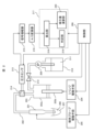
- FIG. 1 is an example of a configuration diagram of an automatic analyzer of the present invention.
- a sample disk 102 in the automatic analyzer 101 can be used to place sample containers 103 in a ring shape.
- the disk rotates clockwise and counterclockwise, moving the sample containers 103 to an access position of the sample dispensing mechanism 104.
- an identification barcode may be attached to the sample container 103.
- the barcode records information linked to the sample ID and information related to the sample type (serum, urine, etc.).
- the barcode attached to the sample container 103 is read by a barcode reader 120.
- the sample dispensing mechanism 104 is composed of a rotation drive mechanism, a vertical drive mechanism, and a dispensing probe. It moves between the sample suction position and the sample discharge position using the rotation drive mechanism and the vertical drive mechanism.
- the reagent storage 105 has a reagent disk 106 and a reagent container holder 107.
- reagent storage has a cooling function to prevent deterioration of reagents over time.
- the reagent container holders 107 are arranged in a double ring on the reagent disk 106, and are designed to hold multiple reagent bottles.
- the reagent disk 106 has a rotation drive mechanism, and the rotational motion moves each reagent bottle to a predetermined position on the circumference.
- the automated analyzer of the present invention is equipped with a reagent dispensing mechanism 108 for biochemical analysis.
- the reagent dispensing mechanism 108 is composed of a rotation drive mechanism, a vertical drive mechanism, and a dispensing probe.
- the reagent dispensing mechanism rotates and descends to the position of a specified type of reagent bottle on the reagent disk 106, and aspirates a specified amount of reagent. After aspirating the reagent, the dispensing mechanism rises. It then rotates and descends to the reagent ejection destination (a specified reaction cell on the reaction disk 109), and ejects the reagent.
- biochemical analysis flow is explained in the order of processing (sample dispensing, reagent dispensing, reaction, and detection).
- the specimen dispensing mechanism 104 dispenses a predetermined amount of sample into a predetermined reaction cell on the reaction disk 109.
- the reaction disk 109 then rotates, moving the reaction cell into which the sample has been discharged to an access position for the reagent dispensing mechanism 108.
- the reagent dispensing mechanism 108 dispenses a predetermined amount of reagent into the reaction cell into which the sample has been ejected.
- the reaction disk 109 rotates, and moves the reaction cell into which the sample and reagent have been ejected to the installation position of the stirring unit 110.
- the sample and reagent are then stirred by the stirring unit 110.
- the reaction disk 109 is kept at an appropriate temperature to promote the reaction between the sample and the reagent.
- the reaction disk 109 rotates and moves the reaction cell containing the reaction liquid after the completion of the reaction to the installation position of the biochemical detection unit 111. After that, the reaction signal is measured by the detection section in the biochemical detection unit 111. After the signal measurement, the reaction liquid is discharged from the reaction cell by the reaction cell cleaning mechanism 112.
- the automatic analyzer further includes a control unit 113 and an operation unit 114 that control the operation of the entire automatic analyzer.
- the control unit 113 is composed of, for example, a hardware board and a computer, and is connected to a storage device 115 such as a hard disk.
- the operation unit 114 is composed of a display unit 117, which is a display with a touch panel, and input devices such as a mouse 118 and a keyboard 119.
- the storage device 115 stores, for example, analysis items for samples registered by a user.
- the control unit 113 may be composed of hardware using a dedicated circuit board, or may be composed of software executed by a computer.
- these devices, circuits, and computers are connected by wired or wireless networks, and data is sent and received as appropriate.
- the reagent dispensing mechanism also has a similar configuration, and can implement the liquid dispensing anomaly detection of the present invention. To avoid duplication, we will omit the explanation of the reagent dispensing mechanism.
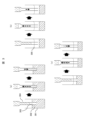
- FIG. 2 is a schematic diagram of the sample dispensing mechanism.
- the sample probe 201 is connected to the sample syringe 203 via the flow path 202, and the insides of the probe and the syringe are filled with liquid.
- the specimen syringe 203 is composed of a cylinder 203a and a plunger 203b, and the plunger 203b is connected to a syringe drive means 204.
- the syringe drive means 204 drives the plunger 203b up and down relative to the cylinder 203a to aspirate and eject the specimen.
- a motor is connected to the sample probe 201 as the sample probe driving means 205, which allows the sample probe to be moved up and down and in a rotational direction to a predetermined position.
- the syringe driving means 204 and the sample probe driving means 205 are controlled by a sample probe control unit 206 (abbreviated as "control unit” in Figure 2).
- segmented air a predetermined amount of air (called segmented air) is aspirated into the sample probe prior to the aspirating operation to prevent the liquid filling the sample probe 201 from mixing with the sample 208.
- the specimen probe 201 is lowered by the specimen probe driving means 205 until it reaches the sample 208, and then a suction operation is performed.
- the amount of descent of the sample probe at this time is determined by monitoring the amount of change in capacitance caused by the sample probe 201 reaching the liquid surface of the sample 208, and the sample probe control unit 206 controls the sample probe driving means 205 to determine the amount of descent of the sample probe.
- the specimen syringe 203 When the sample suction operation is completed, the specimen syringe 203 performs a backlash ejection operation to correct the sample ejection amount in the next ejection operation. After that, the specimen probe 201 moves to the sample ejection position, and the specimen syringe 203 performs the ejection operation.
- the cleaning water 211 in the water supply tank 210 is sprayed at high pressure by the water supply pump 209, thereby cleaning the sample probe 201.
- the flow path to the water supply tank is opened and closed by the solenoid valve 212.
- the solenoid valve 212 is controlled by the sample probe control unit 206.
- the pressure sensor 213 for measuring the pressure in the flow path 202 is connected to a flow path system including the sample probe 201, the flow path 202, and the sample syringe 203 via a branch block 214.
- a branch block 214 In order to measure the pressure fluctuations of the sample probe 201 with good sensitivity, it is desirable to install the pressure sensor 213 as close to the sample probe 201 as possible.
- the output value of the pressure sensor 213 is amplified by a signal amplifier 215 and converted to a digital signal by an A/D converter 216.
- the digitally converted signal is sent to a calculation unit 218, which calculates a judgment index for judging whether the aspirate was successful (determining whether the sample was empty) using the method described below.
- the judgment unit 219 compares the judgment index found by the calculation unit 218 with a threshold value to judge whether the sample was aspirated successfully.
- the operation timing of each mechanism is defined within a specified time cycle, and continuous dispensing is performed by repeating this cycle.
- Figure 3 shows the specimen dispensing mechanism (a) aspirating sample 302 in a sample container 301 normally, (b) aspirating empty sample, and (c) aspirating liquid and air.
- the sample dispensing probe 304 detects the sample liquid level from the change in capacitance, and the sample dispensing probe 304 stops below the sample liquid level.
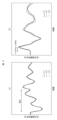
- Figure 4 shows the pressure waveforms obtained in a specimen dispensing unit equipped with a pressure sensor (a) during sample aspira- tion and (b) during backlash discharge.
- the horizontal axis indicates time, and the vertical axis indicates the pressure value in the dispensing channel output by the pressure sensor.
- the pressure waveform changes according to the operation of the specimen syringe.
- the liquid to be aspirated here is assumed to be a specimen, detergent, washing water, etc., but is not particularly limited.
- a reagent dispensing mechanism it is assumed to be a reagent, detergent, washing water, etc., but is not particularly limited.
- L1 shows the pressure waveform when the sample is normally aspirated
- L2 shows the pressure waveform when dry aspirated
- L3 shows the pressure waveform when liquid and air are aspirated.
- the pressure during aspiration is less likely to show a large difference in waveform between normal (L1) and abnormal (L2, L3) conditions compared to the pressure during backlash ejection.
- the drive amount of the sample syringe 203 differs, and therefore the aspiration time depends on the dispensing amount.
- the pressure waveform during backlash dispensing not only shows a large difference compared to the pressure waveform during aspiration, but also occurs at the same timing and with the same amount of operation regardless of the dispensing amount. Therefore, it is easier to create judgment parameters to be used in pressure analysis during backlash dispensing compared to pressure waveform analysis during aspiration.
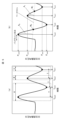
- FIG. 5 shows a method of analyzing the damping rate using a waveform during backlash ejection ((a) Acquisition of maximum value, minimum value, and periodic information (b) Acquisition of baseline and amplitude information).
- the maximum value in a certain section (time width ⁇ ) near the time of backlash ejection is set to the initial maximum value Pmax0
- the minimum value is set to the initial minimum value Pmin0 .
- the times at which the maximum value Pmax0 and the minimum value Pmin0 are taken are set to tmax0 and tmin0, respectively.
- the time difference between tmax0 and tmin0 is set to the period T, and the maximum value in a section of width ⁇ with the time after the period T has elapsed from tmin0 as the median is set to the first maximum value Pmax1 , and the time at this time is set to tmax1 .
- the minimum value in the section of the width of ⁇ whose median value is the time after the period T has elapsed from t max1 , is set as the first minimum value P min1 , and the time at this point is set as t min1 .
- the same procedure may be repeated to obtain more maximum and minimum values.
- the method of obtaining the maximum and minimum values is not limited to this method, and for example, multiple time intervals may be defined, and the maximum value for each interval may be set as the maximum value, and the minimum value for each interval may be set as the minimum value.
- a baseline is obtained to obtain the amplitude of the waveform.
- the vertical axis of the pressure waveform is pressure
- the horizontal axis is time
- the coordinates are shown in the form of (pressure, time).
- the midpoint M0 (( tmax0 + tmin0 )/2, ( Pmax0 + Pmin0 )/2) of a line connecting the point where the initial maximum value is obtained and the point where the initial minimum value is obtained
- the midpoint M1 (( tmax1 + tmin1 )/2, ( Pmax1 + Pmin1 )/2) of a line connecting the point where the first maximum value is obtained and the point where the first minimum value is obtained are obtained.
- the line connecting these midpoints M0 and M1 is determined as the baseline.
- the method of obtaining the baseline is not limited to this method, and for example, a baseline that is a straight line horizontal to the time axis and has an arbitrary pressure value may be used.
- the amplitude is calculated.
- the distance between the initial maximum value P max0 and the baseline at time t max0 when the initial maximum value is obtained is set as the initial amplitude A0 .
- the distance between the first maximum value P max1 and the baseline at time t max1 when the first maximum value is obtained is set as the first amplitude A1 .
- the method of calculating the amplitude is not limited to this method.
- the difference between the pressure value of the initial maximum value and the pressure value of the initial minimum value may be set as the initial amplitude, and the difference between the pressure value of the first maximum value and the pressure value of the first minimum value may be set as the first amplitude.
- the second amplitude A2 and subsequent amplitudes may be calculated.
- the attenuation rate is calculated.
- the attenuation rate may be calculated using the second amplitude A2 and onward. Two or more attenuation rates may also be calculated.
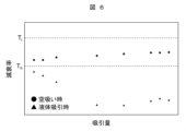
- FIG. 6 is a diagram comparing the attenuation rate during normal aspiration and dry aspiration. Under each dispensing volume condition, the attenuation rate during normal aspiration and liquid aspiration can be polarized.
- the attenuation rate calculated by the calculation unit 218 is compared with threshold values Th and Ti prestored in the judgment unit 219, and if the attenuation rate is smaller than the threshold Th, it is judged to be normal, if the attenuation rate is greater than Th and less than Ti , it is judged to be dry aspiration, and if the attenuation rate is greater than Ti , it is judged to be a malfunction of the device.
- the dry suction judgment may be performed using two or more attenuation rates. Also, instead of using only the attenuation rate, a judgment may be performed using a combination of the attenuation rate and the period T as a judgment parameter. Furthermore, the threshold value T h may be variable depending on the dispensed amount and the liquid properties of the sample.
- Figure 7 shows the process flow for detecting abnormal dispensing during sample dispensing.
- the specimen dispensing mechanism performs a backlash operation following a sample aspirating operation (S701).
- the determination unit 219 calculates the attenuation rate from the pressure value in the flow path during this backlash ejection operation (S702).
- a determination is made as to whether the aspiration is normal or not based on the magnitude relationship between the threshold value stored in the determination unit 219 and the attenuation rate (S703).
- the sample dispensing is determined to be normal aspirating (S704). If the attenuation rate does not fall within the normal determination range, it is determined whether the suction is an empty suction based on the magnitude relationship between the threshold value stored in the determination unit 219 and the attenuation rate (S705).
- the sample dispensing is judged to be dry aspiration (S706). If the attenuation rate does not fall within the dry aspiration judgment range, it is judged that a hardware abnormality occurred during the sample dispensing process (S707).
- a threshold value for when completely empty aspirate is performed and a threshold value for when both air and sample are aspirated may be set to classify the degree of abnormal suction.
- the judgment unit 219 may infer the cause based on the estimated degree of abnormality.
- the determination unit 219 may perform a determination not only based on the attenuation rate, but also by combining the value calculated by the calculation unit 218, for example, the period T, as a determination parameter.
- the present invention can provide an automatic analyzer and an automatic analysis method that can easily and accurately detect abnormalities in liquid dispensing. It can also provide an automatic analyzer and an automatic analysis method that estimates the cause of an abnormality based on the degree of the abnormality when determining the abnormality.
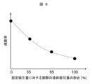
- Figure 8 shows the relationship between the attenuation rate and the ratio of the actual suction volume to the set suction volume when attempting to suck in a certain set suction volume.
- the attenuation rate when air and liquid are sucked in deviates from the attenuation rate when liquid is sucked in according to the set value, and the degree of deviation increases in proportion to the amount of air sucked in.
- an approximation curve for estimating the actual suction volume can be obtained.
- this approximation curve for estimating the actual suction volume in the suction volume calculation unit 220 in advance, it becomes possible to calculate the amount of liquid suctioned during the suction operation when determining whether dry suction is occurring.
Landscapes
- Physics & Mathematics (AREA)
- Health & Medical Sciences (AREA)
- Life Sciences & Earth Sciences (AREA)
- Chemical & Material Sciences (AREA)
- Analytical Chemistry (AREA)
- Biochemistry (AREA)
- General Health & Medical Sciences (AREA)
- General Physics & Mathematics (AREA)
- Immunology (AREA)
- Pathology (AREA)
- Automatic Analysis And Handling Materials Therefor (AREA)
Abstract
Description
また、閾値Thは分注量や試料の液性に応じて可変にしてもよい。
減衰率が正常判定範囲内に入らなかった場合、判定部219に記憶されている閾値と減衰率の大小関係から当該吸引が空吸いか判定を実施する(S705)。
Claims (9)
- 液体に対して吸引及び/又は吐出の工程を含む分注動作を行うプローブと、
前記プローブで液体を分注するための圧力変動を発生させるシリンジと、
前記プローブと前記シリンジを接続する流路と、
液体分注時における前記流路内の圧力を測定するセンサと、
前記シリンジの所定動作後に前記センサにより測定された圧力の経時変化波形の減衰率を算出する算出部と、
前記算出部で算出された減衰率に基づいて、液体分注時の工程に異常があったか否かを判定する判定部と、
を備えることを特徴とする自動分析装置。 - 前記所定動作は、前記シリンジの機械的ガタを解消するためのバックラッシュ吐出であることを特徴とする、請求項1記載の自動分析装置。
- 前記算出部は、前記圧力の経時変化波形の所定区間における極大値と極小値から圧力波形のベースラインを算出し、前記ベースラインと前記極大値の差分または前記ベースラインと前記極小値の差分の比率の推移に基づいて、前記減衰率を算出することを特徴とする、請求項1記載の自動分析装置。
- 前記算出部は、更に前記圧力の経時変化波形の振動周期を算出し、前記判定部は前記振動周期を前記判定に用いることを特徴とする、請求項1記載の自動分析装置。
- 前記判定部は、予め定めた閾値と前記減衰率及び/または前記振動周期を比較して前記判定を行うことを特徴とする、請求項1または4に記載の自動分析装置。
- 前記閾値は、液体吸引時に空気も吸引した場合の前記減衰率及び/または前記振動周期に基づき定められた閾値であることを特徴とする、請求項5記載の自動分析装置。
- 前記閾値は、前記液体の分注量に応じて複数の閾値を有することを特徴とする、請求項6記載の自動分析装置。
- 前記閾値は、前記プローブが吸引する液体の液性に応じて複数の閾値を有することを特徴とする、請求項6記載の自動分析装置。
- 液体に対して吸引及び/又は吐出の工程を含む分注動作を行うプローブと、
前記プローブで液体を分注するための圧力変動を発生させるシリンジと、
前記プローブと前記シリンジを接続する流路と、
液体分注時における前記流路内の圧力を測定するセンサと、
を備えた自動分析装置の異常判定方法であって、
前記シリンジの所定動作後に前記センサにより圧力の経時変化波形を取得する波形取得ステップと、
前記波形取得ステップで取得された圧力の経時変化波形に基づき圧力の減衰率を算出する減衰率算出ステップと、
前記減衰率算出ステップで算出された減衰率に基づいて、液体分注時の工程に異常があったか否かを判定する異常判定ステップと、
を少なくとも含むことを特徴とする自動分析装置の異常判定方法。
Priority Applications (3)
| Application Number | Priority Date | Filing Date | Title |
|---|---|---|---|
| CN202480015302.8A CN120769989A (zh) | 2023-06-09 | 2024-05-02 | 自动分析装置以及其异常判定方法 |
| JP2025525990A JPWO2024252827A1 (ja) | 2023-06-09 | 2024-05-02 | |
| EP24819064.7A EP4726396A1 (en) | 2023-06-09 | 2024-05-02 | Automated analyzing device and abnormality determining method for same |
Applications Claiming Priority (2)
| Application Number | Priority Date | Filing Date | Title |
|---|---|---|---|
| JP2023095708 | 2023-06-09 | ||
| JP2023-095708 | 2023-06-09 |
Publications (1)
| Publication Number | Publication Date |
|---|---|
| WO2024252827A1 true WO2024252827A1 (ja) | 2024-12-12 |
Family
ID=93795233
Family Applications (1)
| Application Number | Title | Priority Date | Filing Date |
|---|---|---|---|
| PCT/JP2024/016844 Ceased WO2024252827A1 (ja) | 2023-06-09 | 2024-05-02 | 自動分析装置およびその異常判定方法 |
Country Status (4)
| Country | Link |
|---|---|
| EP (1) | EP4726396A1 (ja) |
| JP (1) | JPWO2024252827A1 (ja) |
| CN (1) | CN120769989A (ja) |
| WO (1) | WO2024252827A1 (ja) |
Citations (4)
| Publication number | Priority date | Publication date | Assignee | Title |
|---|---|---|---|---|
| JP2009058318A (ja) | 2007-08-31 | 2009-03-19 | Hitachi High-Technologies Corp | 自動分析装置 |
| WO2018147003A1 (ja) * | 2017-02-07 | 2018-08-16 | 株式会社日立ハイテクノロジーズ | 自動分析装置 |
| JP2018130844A (ja) * | 2017-02-13 | 2018-08-23 | 株式会社リコー | 液体吐出ヘッド、液体吐出装置、メンテナンス方法および制御プログラム |
| JP2021089232A (ja) * | 2019-12-05 | 2021-06-10 | 株式会社日立ハイテク | 自動分析装置及び分注方法 |
-
2024
- 2024-05-02 EP EP24819064.7A patent/EP4726396A1/en active Pending
- 2024-05-02 WO PCT/JP2024/016844 patent/WO2024252827A1/ja not_active Ceased
- 2024-05-02 JP JP2025525990A patent/JPWO2024252827A1/ja active Pending
- 2024-05-02 CN CN202480015302.8A patent/CN120769989A/zh active Pending
Patent Citations (4)
| Publication number | Priority date | Publication date | Assignee | Title |
|---|---|---|---|---|
| JP2009058318A (ja) | 2007-08-31 | 2009-03-19 | Hitachi High-Technologies Corp | 自動分析装置 |
| WO2018147003A1 (ja) * | 2017-02-07 | 2018-08-16 | 株式会社日立ハイテクノロジーズ | 自動分析装置 |
| JP2018130844A (ja) * | 2017-02-13 | 2018-08-23 | 株式会社リコー | 液体吐出ヘッド、液体吐出装置、メンテナンス方法および制御プログラム |
| JP2021089232A (ja) * | 2019-12-05 | 2021-06-10 | 株式会社日立ハイテク | 自動分析装置及び分注方法 |
Non-Patent Citations (1)
| Title |
|---|
| See also references of EP4726396A1 |
Also Published As
| Publication number | Publication date |
|---|---|
| EP4726396A1 (en) | 2026-04-15 |
| CN120769989A (zh) | 2025-10-10 |
| JPWO2024252827A1 (ja) | 2024-12-12 |
Similar Documents
| Publication | Publication Date | Title |
|---|---|---|
| US9335335B2 (en) | Automatic analyzer | |
| CN103748471B (zh) | 自动分析装置 | |
| US7477997B2 (en) | Method for ascertaining interferants in small liquid samples in an automated clinical analyzer | |
| US7634378B2 (en) | Detection of insufficient sample during aspiration with a pipette | |
| JP4686100B2 (ja) | 流体移動の完全性を確かめる方法 | |
| EP3594694B1 (en) | Automatic analysis device | |
| JP6018828B2 (ja) | 自動分析装置 | |
| JP7269869B2 (ja) | 自動分析装置及び分注方法 | |
| US20120291532A1 (en) | Methods, Systems, And Apparatus To Determine A Clot Carryout Condition Upon Probe Retraction During Sample Aspiration And Dispensing | |
| CN101377521A (zh) | 自动分析装置 | |
| JP2013054014A (ja) | 自動分析装置 | |
| JP2004271266A (ja) | 分注装置およびそれを用いた自動分析装置 | |
| JP7200357B2 (ja) | 実験器具の動作方法 | |
| JP4045211B2 (ja) | 自動分析装置 | |
| WO2021079645A1 (ja) | 自動分析装置および試薬の分注方法 | |
| WO2025197528A1 (ja) | 自動分析装置 | |
| JP2015031586A (ja) | 分析装置及び液体吸引装置 | |
| WO2024252827A1 (ja) | 自動分析装置およびその異常判定方法 | |
| JP7659447B2 (ja) | 分注装置、自動分析装置及び分注方法 | |
| WO2025115474A1 (ja) | 自動分析装置および分注方法 |
Legal Events
| Date | Code | Title | Description |
|---|---|---|---|
| 121 | Ep: the epo has been informed by wipo that ep was designated in this application |
Ref document number: 24819064 Country of ref document: EP Kind code of ref document: A1 |
|
| DPE1 | Request for preliminary examination filed after expiration of 19th month from priority date (pct application filed from 20040101) | ||
| ENP | Entry into the national phase |
Ref document number: 2025525990 Country of ref document: JP Kind code of ref document: A |
|
| WWE | Wipo information: entry into national phase |
Ref document number: 2025525990 Country of ref document: JP |
|
| WWE | Wipo information: entry into national phase |
Ref document number: 202480015302.8 Country of ref document: CN |
|
| WWP | Wipo information: published in national office |
Ref document number: 202480015302.8 Country of ref document: CN |
|
| WWE | Wipo information: entry into national phase |
Ref document number: 2024819064 Country of ref document: EP |
|
| NENP | Non-entry into the national phase |
Ref country code: DE |
|
| ENP | Entry into the national phase |
Ref document number: 2024819064 Country of ref document: EP Effective date: 20260109 |
|
| ENP | Entry into the national phase |
Ref document number: 2024819064 Country of ref document: EP Effective date: 20260109 |
|
| ENP | Entry into the national phase |
Ref document number: 2024819064 Country of ref document: EP Effective date: 20260109 |
|
| ENP | Entry into the national phase |
Ref document number: 2024819064 Country of ref document: EP Effective date: 20260109 |
|
| ENP | Entry into the national phase |
Ref document number: 2024819064 Country of ref document: EP Effective date: 20260109 |
|
| WWP | Wipo information: published in national office |
Ref document number: 2024819064 Country of ref document: EP |