WO2024252829A1 - Dispositif de positionnement et de fixation - Google Patents
Dispositif de positionnement et de fixation Download PDFInfo
- Publication number
- WO2024252829A1 WO2024252829A1 PCT/JP2024/016940 JP2024016940W WO2024252829A1 WO 2024252829 A1 WO2024252829 A1 WO 2024252829A1 JP 2024016940 W JP2024016940 W JP 2024016940W WO 2024252829 A1 WO2024252829 A1 WO 2024252829A1
- Authority
- WO
- WIPO (PCT)
- Prior art keywords
- positioning
- base body
- fixing device
- cylinder body
- diameter portion
- Prior art date
- Legal status (The legal status is an assumption and is not a legal conclusion. Google has not performed a legal analysis and makes no representation as to the accuracy of the status listed.)
- Ceased
Links
Images


Classifications
-
- B—PERFORMING OPERATIONS; TRANSPORTING
- B23—MACHINE TOOLS; METAL-WORKING NOT OTHERWISE PROVIDED FOR
- B23Q—DETAILS, COMPONENTS, OR ACCESSORIES FOR MACHINE TOOLS, e.g. ARRANGEMENTS FOR COPYING OR CONTROLLING; MACHINE TOOLS IN GENERAL CHARACTERISED BY THE CONSTRUCTION OF PARTICULAR DETAILS OR COMPONENTS; COMBINATIONS OR ASSOCIATIONS OF METAL-WORKING MACHINES, NOT DIRECTED TO A PARTICULAR RESULT
- B23Q1/00—Members which are comprised in the general build-up of a form of machine, particularly relatively large fixed members
- B23Q1/0063—Connecting non-slidable parts of machine tools to each other
- B23Q1/0072—Connecting non-slidable parts of machine tools to each other using a clamping opening for receiving an insertion bolt or nipple
Definitions
- This technology relates to a positioning and fixing device.
- Positioning and fixing devices capable of positioning and fixing an object to be fixed relative to a base body have been known for some time.
- Examples of background technology to this technology include those described in the following Patent Documents 1 to 6.
- the purpose of this technology is to provide a compact positioning and fixing device.
- the present technology can provide the following positioning and fixing device:
- a positioning and fixing device capable of attracting and fixing an object to be fixed to a first surface of a base body and positioning the object to be fixed relative to the base body, comprising a fluid pressure cylinder fixed to the base body and a connecting member having an outer circumferential surface and attachable to the object to be fixed, the fluid pressure cylinder including a cylinder body, an annular piston member capable of reciprocating in a first direction relative to the cylinder body, an engaging device that engages with the outer circumferential surface of the connecting member and drives the connecting member in the first direction in accordance with the reciprocating movement of the piston member, and a rod member fixed to the cylinder body and fitted to the inner circumferential side of the piston member.
- the cylinder body includes a small diameter portion embedded in the base body and a large diameter portion that protrudes in a first direction from a second surface side of the base body opposite the first surface and has an outer diameter larger than the small diameter portion, the engaging device is provided in the small diameter portion of the cylinder body, a cylinder chamber that reciprocates the piston member is formed in the large diameter portion of the cylinder body, a working medium passage that can supply a working medium from the inner periphery side of the piston member to the cylinder chamber is formed in the rod member, and a positioning and fixing device that positions the fixed object in the first direction by abutting it against the first surface of the base body by driving the connecting member in the first direction via the engaging device.
- a positioning and fixing device according to any one of [1] to [3], in which a step surface is formed between the small diameter portion and the large diameter portion of the cylinder body, and the step surface abuts against the second surface of the base body.
- a positioning and fixing device according to any one of [1] to [4], in which the base body abuts against the object to be fixed in an area adjacent to the small diameter portion on the first surface.
- a positioning and fixing device according to any one of [1] to [8], in which the engaging member includes a plurality of steel balls arranged in a line around the circumference of the cylinder body, and the connecting member includes engaging recesses formed so that the plurality of steel balls can come into contact with each other.
- a positioning and fixing device according to any one of [1] to [10], wherein the rod member has a recess for receiving the tip end of the connecting member.
- This technology makes it possible to obtain a compact positioning and fixing device.
- FIG. 2 is a cross-sectional view showing a clamped state of the positioning and fixing device according to one embodiment. This is a cross-sectional view taken along line II-II in FIG. 2 is an enlarged view of the periphery of an engaging member in the positioning and fixing device shown in FIG. 1 .
- 1 is a cross-sectional view showing a positioning and fixing device according to an embodiment in an unclamped state (fixed object and connecting member).
- FIG. 1 is a cross-sectional view showing a positioning and fixing device according to one embodiment in an unclamped state (base body and fluid pressure cylinder);
- FIG. FIG. 11 is a cross-sectional view showing a clamped state of a positioning and fixing device according to another embodiment.
- the words “comprise,” “include,” and “have” are open-ended. In other words, when a certain configuration is included, other configurations may or may not be included.
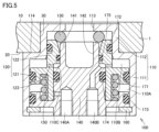
- FIG. 1 is a cross-sectional view showing the clamped state of a positioning and fixing device according to one embodiment
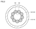
- FIG. 2 is a cross-sectional view taken along line II-II in FIG. 1.
- connecting member 200 and bolt 200A are not shown in FIG. 2.
- the up-down direction in FIG. 1 may be referred to as the "vertical direction” or "first direction”
- the left-right direction in FIG. 1 or the direction perpendicular to the paper surface may be referred to as the "horizontal direction” or "second direction.”
- the positioning and fixing device includes a fluid pressure cylinder 100 fixed to a base body 1, and a connecting member 200 attached to a fixing object 2 by a bolt 200A.
- the positioning and fixing device attracts and fixes the fixed object 2 to the first surface 10, which serves as the reference seat surface (reference surface) of the base body 1.
- the fixed object 2 comes into contact with the first surface 10 of the base body 1, making it possible to position the fixed object 2 relative to the base body 1 in the vertical direction.
- Examples of the fixed object 2 include a work pallet on which a workpiece to be cut is attached, or a mold, but the fixed object 2 in this technology is not limited to these.
- the fluid pressure cylinder 100 includes a cylinder body 110, a piston member 120, an engagement member 130, a rod member 140, a biasing member 150, and a stopper 160.
- the cylinder body 110 includes a large diameter portion 111, a small diameter portion 112, a hole portion 113, and a step surface 114.
- the large diameter portion 111 protrudes vertically (in the first direction) from the second surface 20 (rear surface) of the base body 1.
- the large diameter portion 111 has a larger outer diameter than the small diameter portion 112.
- the small diameter portion 112 is embedded in the base body 1. More specifically, the small diameter portion 112 is pressed into the insertion hole 30 of the base body 1 from the second surface 20 side. The first surface 10 of the base body 1 and the fixed object 2 come into contact in the area adjacent to the small diameter portion 112 of the cylinder body 110.
- the hole 113 is formed on the upper surface of the small diameter portion 112 so as to face the object to be fixed 2.
- the inner circumferential surface of the hole 113 abuts against the outer circumferential surface 210 of the connecting member 200.
- the hole 113 of the cylinder body 110 abuts against the outer circumferential surface 210 of the connecting member 200, making it possible to position the object to be fixed 2 relative to the base body 1 in the horizontal direction (second direction).
- the positioning in the horizontal direction may be positioning in both the left-right direction in FIG. 1 and the direction perpendicular to the paper surface, or may be positioning in only one of the above two directions. Furthermore, positioning in the horizontal direction (second direction) is not essential in this technology, and the positioning and fixing device may only perform positioning in the vertical direction (first direction).
- the step surface 114 is formed between the large diameter portion 111 and the small diameter portion 112.
- the step surface 114 abuts against the second surface 20 of the base body 1.
- the cylinder body 110 defines a cylinder chamber 110A (first chamber) and a cylinder chamber 110B (second chamber).
- the cylinder chambers 110A and 110B are partitioned by a piston member 120.
- the cylinder chambers 110A and 110B are formed in the large diameter portion 111 of the cylinder body 110.
- the piston member 120 is fitted into the large diameter portion 111 of the cylinder body 110.
- the piston member 120 is an annular member, and the rod member 140 is fitted into its inner periphery.
- the piston member 120 can be driven to reciprocate vertically by the pressure of the working medium (typically working air, but not limited to this, and may be working oil) supplied to and discharged from the cylinder chambers 110A and 110B.
- the working medium typically working air, but not limited to this, and may be working oil
- the piston member 120 includes a first portion 121 that fits into the large diameter portion 111 of the cylinder body 110, and a second portion 122 that fits into the small diameter portion 112 of the cylinder body 110. Between the first portion 121 and the second portion 122, a through hole 123 is formed that extends from the internal space 110C formed on the inner periphery of the piston member 120 to the cylinder chamber 110B formed on the outer periphery of the piston member 120.
- the engaging device 130 engages with the outer peripheral surface of the connecting member 200 and drives the connecting member 200 vertically (in the opposite direction to the piston member 120) while moving horizontally in accordance with the vertical reciprocating motion of the piston member 120.
- the engaging device 130 is provided on the small diameter portion 112 of the cylinder body 110.
- the engaging device 130 includes a number of steel balls arranged in a line around the cylinder body 110.
- the connecting member 200 includes engaging recesses 220 formed so that the steel balls can come into contact with each other.
- the engaging recesses 220 are formed over the entire circumferential direction of the connecting member 200 such that the outer circumferential surface 210 of the connecting member 200 is recessed radially inward.
- the rod member 140 is fixed to the cylinder body 110.
- the rod member 140 fits into the inner periphery of the piston member 120.
- the rod member 140 is formed with air passages 140A, 140B (working medium passages) that can supply air (working medium) from the inner periphery of the piston member 120 to the cylinder chambers 110A, 110B.
- the air passage 140A communicates with the cylinder chamber 110A.
- the through hole 123 formed in the piston member 120 communicates between the internal space 110C, which communicates with the air passage 140B, and the cylinder chamber 110B. As a result, the air passage 140B communicates with the cylinder chamber 110B.
- the air passages 140A, 140B are supplied with working air from below in the vertical direction.
- the air passages 140A, 140B have a portion that extends vertically from the input port and a portion that extends radially or diagonally to reach the outer periphery of the rod member 140.
- the input port of the air passages 140A, 140B is formed on the underside of the rod member 140, and its center is located in an area that overlaps with the engaging device 130 when viewed from the vertical direction (first direction), or in an area that is more inward than the engaging device 130.
- the working air supplied to the air passages 140A, 140B is supplied to the cylinder chambers 110A, 110B that reach an area more outward than the engaging device 130 when viewed from the vertical direction (first direction).
- the tip side of the rod member 140 is provided with a holding portion 141 that holds the engaging device 130 provided on the small diameter portion 112 of the cylinder body 110, and a recess 142 that receives the tip side of the connecting member 200.
- the biasing member 150 is housed in the cylinder chamber 110A on the lock side (clamp side).
- the biasing member 150 biases the piston member 120 vertically upward. In other words, the biasing member 150 biases the piston member 120 in the direction in which the fixed object 2 is fixed. This allows the fixed object 2 to remain positioned and fixed even if the supply of air pressure is interrupted.
- the stopper 160 is provided to fix the rod member 140 to the cylinder body 110.
- the stopper 160 restricts the displacement of the rod member 140 relative to the cylinder body 110.
- Sealing members 171, 172, 173, 174, and 175 are provided inside the cylinder body 110.
- the sealing member 171 is provided at the sliding portion between the large diameter portion 111 of the cylinder body 110 and the first part 121 of the piston member 120.
- the sealing member 172 is provided at the sliding portion between the small diameter portion 112 of the cylinder body 110 and the second part 122 of the piston member 120.
- the sealing member 173 is provided at the fitting portion between the rod member 140 and the large diameter portion 111 of the cylinder body 110.
- the sealing members 174 and 175 are each provided at the sliding portion between the inner surface of the piston member 120 and the rod member 140.
- the sealing member 171 seals between the cylinder chambers 110A and 110B.
- the sealing member 172 seals between the cylinder chamber 110B and the outside of the cylinder body 110.
- the seal member 173 seals between the cylinder chamber 110A and the outside of the cylinder body 110.
- the seal member 174 seals between the cylinder chamber 110A and the internal space 110C.
- the seal member 175 seals between the internal space 110C and the outside of the cylinder body 110.
- the seal members 171, 172, 173, 174, and 175 are, for example, O-rings.
- Figure 3 is an enlarged view of the area around the engaging device 130.
- the second portion 122 of the piston member 120 is formed with a tapered surface 122A that slopes radially outward as it approaches the fixed object 2
- the holding portion 141 of the rod member 140 is formed with a tip surface 141A that slopes in the opposite direction to the tapered surface 122A of the piston member 120.
- the piston member 120 When air pressure is supplied to the cylinder chamber 110A, the piston member 120 is driven upward (towards the small diameter portion 112 of the cylinder body 110). When the piston member 120 is driven upward, the engaging member 130 held by the holding portion 141 of the rod member 140 is pressed radially inward of the connecting member 200 by the tapered surface 122A. The engaging member 130 pressed radially inward engages with the engaging recess 220 of the connecting member 200, driving the connecting member 200 vertically downward.
- the object to be fixed 2 is pushed downward.
- the piston member 120 is driven in a direction approaching the object to be fixed 2, and the engaging member 130 of the fluid pressure cylinder 100 is engaged with the engaging recess 220 of the connecting member 200, thereby fixing the object to be fixed 2 to the base body 1.
- the object to be fixed 2 is pushed down until it abuts against the first surface 10 of the base body 1.
- the first surface 10 realizes the positioning of the object to be fixed 2 in the vertical direction (first direction).
- the connecting member 200 When the connecting member 200 is driven downward, the outer circumferential surface 210 of the connecting member 200 engages with the hole 113 of the cylinder body 110. Therefore, the connecting member 200 descends while being guided by the hole 113 of the cylinder body 110. This achieves positioning of the fixed object 2 in the horizontal direction (second direction).
- Figures 4 and 5 are cross-sectional views showing the above-mentioned positioning and fixing device in an unclamped state ( Figure 4 shows the fixed object 2 and the connecting member 200, and Figure 5 shows the base body 1 and the fluid pressure cylinder 100).
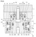
- FIG. 6 is a cross-sectional view showing a clamped state of a positioning and fixing device according to a modified example.
- the mounting direction of the bolt 200A for fixing the connecting member 200 to the fixed object 2 is different from the examples of FIG. 1 to FIG. 5.
- the above-mentioned air passages 140A, 140B (working medium passages) are formed in the rod member 140.
- an air passage 140C is formed that extends from the lower end of the rod member 140 to the recess 142.
- the inside of the cylinder body 110 can be cleaned by air (blow air) supplied to the recess 142 from the air passage 140C.
- air blow air
- detecting the air pressure in the air passage 140C it is also possible to detect whether the fixed object 2 is in close contact with the base body 1.
- air passages 140A, 140B are provided in the rod member 140 that is fitted to the inner periphery of the piston member 120, and the operating air is supplied from the inner periphery of the cylinder chambers 110A, 110B, allowing the operating air to be supplied and discharged from the piping connected below the fluid pressure cylinder 100, making it possible to make the entire mechanism smaller than when an air passage is formed in the base body 1.
- the engaging device 130 that drives the connecting member 200 is provided on the small diameter portion 112 of the cylinder body 110, the small diameter portion 112 is pressed into the insertion hole 30 of the base body 1, and the large diameter portion 111 protrudes from the second surface 20 side of the base body 1, making it possible to miniaturize the entire mechanism in both the vertical and horizontal directions.
- the cylinder body 110 can withstand the external force acting on the fixed object 2, making it possible to miniaturize the entire mechanism while maintaining the clamping force.
Landscapes
- Engineering & Computer Science (AREA)
- Mechanical Engineering (AREA)
- Jigs For Machine Tools (AREA)
- Actuator (AREA)
Abstract
Selon la présente invention, un corps de cylindre comprend : une partie de petit diamètre incorporée dans un corps de base ; et une partie de grand diamètre faisant saillie dans une première direction depuis un second côté de surface sur le côté opposé à une première surface dans le corps de base et ayant un diamètre extérieur plus grand que celui de la partie de petit diamètre. Un outil de mise en prise est disposé sur la partie de petit diamètre du corps de cylindre, et une chambre de cylindre pour imprimer un mouvement de va-et-vient à un élément de piston est formée dans la partie de grand diamètre du corps de cylindre. Un passage de fluide de travail apte à fournir un milieu de travail à la chambre de cylindre à partir d'un côté périphérique interne de l'élément de piston est formé dans un élément de tige. L'entraînement d'un élément de liaison dans la première direction par l'intermédiaire de l'outil de mise en prise permet de mettre en contact un objet à fixer avec la première surface du corps de base et d'assurer le positionnement dans la première direction.
Priority Applications (1)
| Application Number | Priority Date | Filing Date | Title |
|---|---|---|---|
| DE112024001808.4T DE112024001808T5 (de) | 2023-06-05 | 2024-05-07 | Positionier- und Fixiervorrichtung |
Applications Claiming Priority (2)
| Application Number | Priority Date | Filing Date | Title |
|---|---|---|---|
| JP2023092298A JP2024174464A (ja) | 2023-06-05 | 2023-06-05 | 位置決め固定装置 |
| JP2023-092298 | 2023-06-05 |
Publications (1)
| Publication Number | Publication Date |
|---|---|
| WO2024252829A1 true WO2024252829A1 (fr) | 2024-12-12 |
Family
ID=93795268
Family Applications (1)
| Application Number | Title | Priority Date | Filing Date |
|---|---|---|---|
| PCT/JP2024/016940 Ceased WO2024252829A1 (fr) | 2023-06-05 | 2024-05-07 | Dispositif de positionnement et de fixation |
Country Status (3)
| Country | Link |
|---|---|
| JP (1) | JP2024174464A (fr) |
| DE (1) | DE112024001808T5 (fr) |
| WO (1) | WO2024252829A1 (fr) |
Citations (3)
| Publication number | Priority date | Publication date | Assignee | Title |
|---|---|---|---|---|
| JPH09285925A (ja) * | 1996-04-23 | 1997-11-04 | Kosmek Ltd | クランプ装置 |
| US20070210501A1 (en) * | 2004-02-09 | 2007-09-13 | Zero-Point Systems Gunther Stark Gmbh | Quick-Action Clamping Cylinder With An Anti-Blocking Safety Device |
| WO2023053761A1 (fr) * | 2021-09-28 | 2023-04-06 | パスカルエンジニアリング株式会社 | Dispositif d'accouplement et dispositif de serrage |
Family Cites Families (4)
| Publication number | Priority date | Publication date | Assignee | Title |
|---|---|---|---|---|
| ITTV20120129A1 (it) | 2012-07-11 | 2014-01-12 | Almerino Canuto | Dispositivo di compensazione del disassamento in sistemi di bloccaggio automatici |
| JP6863582B2 (ja) | 2017-07-10 | 2021-04-21 | パスカルエンジニアリング株式会社 | ロボットアームカップリング装置 |
| DE202018104109U1 (de) | 2018-07-17 | 2018-07-23 | Andreas Maier Gmbh & Co. Kg | Spannvorrichtung |
| JP7122748B2 (ja) | 2018-10-30 | 2022-08-22 | パスカルエンジニアリング株式会社 | 位置決め固定装置 |
-
2023
- 2023-06-05 JP JP2023092298A patent/JP2024174464A/ja active Pending
-
2024
- 2024-05-07 WO PCT/JP2024/016940 patent/WO2024252829A1/fr not_active Ceased
- 2024-05-07 DE DE112024001808.4T patent/DE112024001808T5/de active Pending
Patent Citations (3)
| Publication number | Priority date | Publication date | Assignee | Title |
|---|---|---|---|---|
| JPH09285925A (ja) * | 1996-04-23 | 1997-11-04 | Kosmek Ltd | クランプ装置 |
| US20070210501A1 (en) * | 2004-02-09 | 2007-09-13 | Zero-Point Systems Gunther Stark Gmbh | Quick-Action Clamping Cylinder With An Anti-Blocking Safety Device |
| WO2023053761A1 (fr) * | 2021-09-28 | 2023-04-06 | パスカルエンジニアリング株式会社 | Dispositif d'accouplement et dispositif de serrage |
Also Published As
| Publication number | Publication date |
|---|---|
| DE112024001808T5 (de) | 2026-02-26 |
| JP2024174464A (ja) | 2024-12-17 |
Similar Documents
| Publication | Publication Date | Title |
|---|---|---|
| JP5750053B2 (ja) | クランプ装置 | |
| JP5779194B2 (ja) | 位置決め装置 | |
| JP6283219B2 (ja) | クランプ装置 | |
| WO2011108352A1 (fr) | Dispositif de fixation | |
| TWI655992B (zh) | 夾具裝置 | |
| JP2018118333A (ja) | 自動工具交換装置 | |
| TW201702491A (zh) | 流體壓力缸 | |
| KR102282818B1 (ko) | 파지 장치 | |
| CN100478127C (zh) | 定位装置和具有该定位装置的夹持系统 | |
| WO2024070395A1 (fr) | Dispositif de remplacement d'élément | |
| WO2024252829A1 (fr) | Dispositif de positionnement et de fixation | |
| WO2023053761A1 (fr) | Dispositif d'accouplement et dispositif de serrage | |
| JP4877787B2 (ja) | 位置決め装置およびその装置を備えた位置決めシステム | |
| JP7774286B2 (ja) | クランプ装置 | |
| JP2005188670A (ja) | 締結装置 | |
| JP2023173257A (ja) | クランプ装置および回転支持装置 | |
| CN222972185U (zh) | 用于冲压工况的机器人工具快换装置 | |
| KR20180016577A (ko) | 유체압 실린더 | |
| JP3239951U (ja) | クランプ装置 | |
| JP5408984B2 (ja) | クランプ装置 | |
| WO2026053622A1 (fr) | Cylindre à pression de fluide | |
| JP2024033373A (ja) | 位置決め固定装置 |
Legal Events
| Date | Code | Title | Description |
|---|---|---|---|
| 121 | Ep: the epo has been informed by wipo that ep was designated in this application |
Ref document number: 24819066 Country of ref document: EP Kind code of ref document: A1 |
|
| WWE | Wipo information: entry into national phase |
Ref document number: 112024001808 Country of ref document: DE |
|
| WWP | Wipo information: published in national office |
Ref document number: 112024001808 Country of ref document: DE |