WO2024252889A1 - 高強度鋼板、高強度めっき鋼板及びそれらの製造方法並びに部材 - Google Patents
高強度鋼板、高強度めっき鋼板及びそれらの製造方法並びに部材 Download PDFInfo
- Publication number
- WO2024252889A1 WO2024252889A1 PCT/JP2024/018164 JP2024018164W WO2024252889A1 WO 2024252889 A1 WO2024252889 A1 WO 2024252889A1 JP 2024018164 W JP2024018164 W JP 2024018164W WO 2024252889 A1 WO2024252889 A1 WO 2024252889A1
- Authority
- WO
- WIPO (PCT)
- Prior art keywords
- less
- temperature
- cooling
- strength
- content
- Prior art date
- Legal status (The legal status is an assumption and is not a legal conclusion. Google has not performed a legal analysis and makes no representation as to the accuracy of the status listed.)
- Ceased
Links
Classifications
-
- C—CHEMISTRY; METALLURGY
- C22—METALLURGY; FERROUS OR NON-FERROUS ALLOYS; TREATMENT OF ALLOYS OR NON-FERROUS METALS
- C22C—ALLOYS
- C22C38/00—Ferrous alloys, e.g. steel alloys
- C22C38/04—Ferrous alloys, e.g. steel alloys containing manganese
-
- C—CHEMISTRY; METALLURGY
- C21—METALLURGY OF IRON
- C21D—MODIFYING THE PHYSICAL STRUCTURE OF FERROUS METALS; GENERAL DEVICES FOR HEAT TREATMENT OF FERROUS OR NON-FERROUS METALS OR ALLOYS; MAKING METAL MALLEABLE, e.g. BY DECARBURISATION OR TEMPERING
- C21D1/00—General methods or devices for heat treatment, e.g. annealing, hardening, quenching or tempering
- C21D1/18—Hardening; Quenching with or without subsequent tempering
-
- B—PERFORMING OPERATIONS; TRANSPORTING
- B32—LAYERED PRODUCTS
- B32B—LAYERED PRODUCTS, i.e. PRODUCTS BUILT-UP OF STRATA OF FLAT OR NON-FLAT, e.g. CELLULAR OR HONEYCOMB, FORM
- B32B15/00—Layered products comprising a layer of metal
- B32B15/01—Layered products comprising a layer of metal all layers being exclusively metallic
- B32B15/013—Layered products comprising a layer of metal all layers being exclusively metallic one layer being formed of an iron alloy or steel, another layer being formed of a metal other than iron or aluminium
-
- C—CHEMISTRY; METALLURGY
- C21—METALLURGY OF IRON
- C21D—MODIFYING THE PHYSICAL STRUCTURE OF FERROUS METALS; GENERAL DEVICES FOR HEAT TREATMENT OF FERROUS OR NON-FERROUS METALS OR ALLOYS; MAKING METAL MALLEABLE, e.g. BY DECARBURISATION OR TEMPERING
- C21D1/00—General methods or devices for heat treatment, e.g. annealing, hardening, quenching or tempering
- C21D1/18—Hardening; Quenching with or without subsequent tempering
- C21D1/19—Hardening; Quenching with or without subsequent tempering by interrupted quenching
-
- C—CHEMISTRY; METALLURGY
- C21—METALLURGY OF IRON
- C21D—MODIFYING THE PHYSICAL STRUCTURE OF FERROUS METALS; GENERAL DEVICES FOR HEAT TREATMENT OF FERROUS OR NON-FERROUS METALS OR ALLOYS; MAKING METAL MALLEABLE, e.g. BY DECARBURISATION OR TEMPERING
- C21D1/00—General methods or devices for heat treatment, e.g. annealing, hardening, quenching or tempering
- C21D1/18—Hardening; Quenching with or without subsequent tempering
- C21D1/19—Hardening; Quenching with or without subsequent tempering by interrupted quenching
- C21D1/20—Isothermal quenching, e.g. bainitic hardening
-
- C—CHEMISTRY; METALLURGY
- C21—METALLURGY OF IRON
- C21D—MODIFYING THE PHYSICAL STRUCTURE OF FERROUS METALS; GENERAL DEVICES FOR HEAT TREATMENT OF FERROUS OR NON-FERROUS METALS OR ALLOYS; MAKING METAL MALLEABLE, e.g. BY DECARBURISATION OR TEMPERING
- C21D1/00—General methods or devices for heat treatment, e.g. annealing, hardening, quenching or tempering
- C21D1/18—Hardening; Quenching with or without subsequent tempering
- C21D1/25—Hardening, combined with annealing between 300 degrees Celsius and 600 degrees Celsius, i.e. heat refining ("Vergüten")
-
- C—CHEMISTRY; METALLURGY
- C21—METALLURGY OF IRON
- C21D—MODIFYING THE PHYSICAL STRUCTURE OF FERROUS METALS; GENERAL DEVICES FOR HEAT TREATMENT OF FERROUS OR NON-FERROUS METALS OR ALLOYS; MAKING METAL MALLEABLE, e.g. BY DECARBURISATION OR TEMPERING
- C21D8/00—Modifying the physical properties of ferrous metals or ferrous alloys by deformation combined with, or followed by, heat treatment
- C21D8/02—Modifying the physical properties of ferrous metals or ferrous alloys by deformation combined with, or followed by, heat treatment during manufacturing of plates or strips
- C21D8/0221—Modifying the physical properties of ferrous metals or ferrous alloys by deformation combined with, or followed by, heat treatment during manufacturing of plates or strips characterised by the working steps
- C21D8/0226—Hot rolling
-
- C—CHEMISTRY; METALLURGY
- C21—METALLURGY OF IRON
- C21D—MODIFYING THE PHYSICAL STRUCTURE OF FERROUS METALS; GENERAL DEVICES FOR HEAT TREATMENT OF FERROUS OR NON-FERROUS METALS OR ALLOYS; MAKING METAL MALLEABLE, e.g. BY DECARBURISATION OR TEMPERING
- C21D8/00—Modifying the physical properties of ferrous metals or ferrous alloys by deformation combined with, or followed by, heat treatment
- C21D8/02—Modifying the physical properties of ferrous metals or ferrous alloys by deformation combined with, or followed by, heat treatment during manufacturing of plates or strips
- C21D8/0221—Modifying the physical properties of ferrous metals or ferrous alloys by deformation combined with, or followed by, heat treatment during manufacturing of plates or strips characterised by the working steps
- C21D8/0236—Cold rolling
-
- C—CHEMISTRY; METALLURGY
- C21—METALLURGY OF IRON
- C21D—MODIFYING THE PHYSICAL STRUCTURE OF FERROUS METALS; GENERAL DEVICES FOR HEAT TREATMENT OF FERROUS OR NON-FERROUS METALS OR ALLOYS; MAKING METAL MALLEABLE, e.g. BY DECARBURISATION OR TEMPERING
- C21D8/00—Modifying the physical properties of ferrous metals or ferrous alloys by deformation combined with, or followed by, heat treatment
- C21D8/02—Modifying the physical properties of ferrous metals or ferrous alloys by deformation combined with, or followed by, heat treatment during manufacturing of plates or strips
- C21D8/0247—Modifying the physical properties of ferrous metals or ferrous alloys by deformation combined with, or followed by, heat treatment during manufacturing of plates or strips characterised by the heat treatment
- C21D8/0273—Final recrystallisation annealing
-
- C—CHEMISTRY; METALLURGY
- C21—METALLURGY OF IRON
- C21D—MODIFYING THE PHYSICAL STRUCTURE OF FERROUS METALS; GENERAL DEVICES FOR HEAT TREATMENT OF FERROUS OR NON-FERROUS METALS OR ALLOYS; MAKING METAL MALLEABLE, e.g. BY DECARBURISATION OR TEMPERING
- C21D8/00—Modifying the physical properties of ferrous metals or ferrous alloys by deformation combined with, or followed by, heat treatment
- C21D8/02—Modifying the physical properties of ferrous metals or ferrous alloys by deformation combined with, or followed by, heat treatment during manufacturing of plates or strips
- C21D8/04—Modifying the physical properties of ferrous metals or ferrous alloys by deformation combined with, or followed by, heat treatment during manufacturing of plates or strips to produce plates or strips for drawing, e.g. for deep-drawing
- C21D8/041—Modifying the physical properties of ferrous metals or ferrous alloys by deformation combined with, or followed by, heat treatment during manufacturing of plates or strips to produce plates or strips for drawing, e.g. for deep-drawing involving a particular fabrication or treatment of ingot or slab
-
- C—CHEMISTRY; METALLURGY
- C21—METALLURGY OF IRON
- C21D—MODIFYING THE PHYSICAL STRUCTURE OF FERROUS METALS; GENERAL DEVICES FOR HEAT TREATMENT OF FERROUS OR NON-FERROUS METALS OR ALLOYS; MAKING METAL MALLEABLE, e.g. BY DECARBURISATION OR TEMPERING
- C21D8/00—Modifying the physical properties of ferrous metals or ferrous alloys by deformation combined with, or followed by, heat treatment
- C21D8/02—Modifying the physical properties of ferrous metals or ferrous alloys by deformation combined with, or followed by, heat treatment during manufacturing of plates or strips
- C21D8/04—Modifying the physical properties of ferrous metals or ferrous alloys by deformation combined with, or followed by, heat treatment during manufacturing of plates or strips to produce plates or strips for drawing, e.g. for deep-drawing
- C21D8/0421—Modifying the physical properties of ferrous metals or ferrous alloys by deformation combined with, or followed by, heat treatment during manufacturing of plates or strips to produce plates or strips for drawing, e.g. for deep-drawing characterised by the working steps
- C21D8/0426—Hot rolling
-
- C—CHEMISTRY; METALLURGY
- C21—METALLURGY OF IRON
- C21D—MODIFYING THE PHYSICAL STRUCTURE OF FERROUS METALS; GENERAL DEVICES FOR HEAT TREATMENT OF FERROUS OR NON-FERROUS METALS OR ALLOYS; MAKING METAL MALLEABLE, e.g. BY DECARBURISATION OR TEMPERING
- C21D8/00—Modifying the physical properties of ferrous metals or ferrous alloys by deformation combined with, or followed by, heat treatment
- C21D8/02—Modifying the physical properties of ferrous metals or ferrous alloys by deformation combined with, or followed by, heat treatment during manufacturing of plates or strips
- C21D8/04—Modifying the physical properties of ferrous metals or ferrous alloys by deformation combined with, or followed by, heat treatment during manufacturing of plates or strips to produce plates or strips for drawing, e.g. for deep-drawing
- C21D8/0421—Modifying the physical properties of ferrous metals or ferrous alloys by deformation combined with, or followed by, heat treatment during manufacturing of plates or strips to produce plates or strips for drawing, e.g. for deep-drawing characterised by the working steps
- C21D8/0436—Cold rolling
-
- C—CHEMISTRY; METALLURGY
- C21—METALLURGY OF IRON
- C21D—MODIFYING THE PHYSICAL STRUCTURE OF FERROUS METALS; GENERAL DEVICES FOR HEAT TREATMENT OF FERROUS OR NON-FERROUS METALS OR ALLOYS; MAKING METAL MALLEABLE, e.g. BY DECARBURISATION OR TEMPERING
- C21D8/00—Modifying the physical properties of ferrous metals or ferrous alloys by deformation combined with, or followed by, heat treatment
- C21D8/02—Modifying the physical properties of ferrous metals or ferrous alloys by deformation combined with, or followed by, heat treatment during manufacturing of plates or strips
- C21D8/04—Modifying the physical properties of ferrous metals or ferrous alloys by deformation combined with, or followed by, heat treatment during manufacturing of plates or strips to produce plates or strips for drawing, e.g. for deep-drawing
- C21D8/0447—Modifying the physical properties of ferrous metals or ferrous alloys by deformation combined with, or followed by, heat treatment during manufacturing of plates or strips to produce plates or strips for drawing, e.g. for deep-drawing characterised by the heat treatment
- C21D8/0473—Final recrystallisation annealing
-
- C—CHEMISTRY; METALLURGY
- C21—METALLURGY OF IRON
- C21D—MODIFYING THE PHYSICAL STRUCTURE OF FERROUS METALS; GENERAL DEVICES FOR HEAT TREATMENT OF FERROUS OR NON-FERROUS METALS OR ALLOYS; MAKING METAL MALLEABLE, e.g. BY DECARBURISATION OR TEMPERING
- C21D9/00—Heat treatment, e.g. annealing, hardening, quenching or tempering, adapted for particular articles; Furnaces therefor
- C21D9/46—Heat treatment, e.g. annealing, hardening, quenching or tempering, adapted for particular articles; Furnaces therefor for sheet metals
- C21D9/48—Heat treatment, e.g. annealing, hardening, quenching or tempering, adapted for particular articles; Furnaces therefor for sheet metals deep-drawing sheets
-
- C—CHEMISTRY; METALLURGY
- C22—METALLURGY; FERROUS OR NON-FERROUS ALLOYS; TREATMENT OF ALLOYS OR NON-FERROUS METALS
- C22C—ALLOYS
- C22C38/00—Ferrous alloys, e.g. steel alloys
- C22C38/002—Ferrous alloys, e.g. steel alloys containing In, Mg, or other elements not provided for in one single group C22C38/001 - C22C38/60
-
- C—CHEMISTRY; METALLURGY
- C22—METALLURGY; FERROUS OR NON-FERROUS ALLOYS; TREATMENT OF ALLOYS OR NON-FERROUS METALS
- C22C—ALLOYS
- C22C38/00—Ferrous alloys, e.g. steel alloys
- C22C38/005—Ferrous alloys, e.g. steel alloys containing rare earths, i.e. Sc, Y, Lanthanides
-
- C—CHEMISTRY; METALLURGY
- C22—METALLURGY; FERROUS OR NON-FERROUS ALLOYS; TREATMENT OF ALLOYS OR NON-FERROUS METALS
- C22C—ALLOYS
- C22C38/00—Ferrous alloys, e.g. steel alloys
- C22C38/008—Ferrous alloys, e.g. steel alloys containing tin
-
- C—CHEMISTRY; METALLURGY
- C22—METALLURGY; FERROUS OR NON-FERROUS ALLOYS; TREATMENT OF ALLOYS OR NON-FERROUS METALS
- C22C—ALLOYS
- C22C38/00—Ferrous alloys, e.g. steel alloys
- C22C38/02—Ferrous alloys, e.g. steel alloys containing silicon
-
- C—CHEMISTRY; METALLURGY
- C22—METALLURGY; FERROUS OR NON-FERROUS ALLOYS; TREATMENT OF ALLOYS OR NON-FERROUS METALS
- C22C—ALLOYS
- C22C38/00—Ferrous alloys, e.g. steel alloys
- C22C38/08—Ferrous alloys, e.g. steel alloys containing nickel
-
- C—CHEMISTRY; METALLURGY
- C22—METALLURGY; FERROUS OR NON-FERROUS ALLOYS; TREATMENT OF ALLOYS OR NON-FERROUS METALS
- C22C—ALLOYS
- C22C38/00—Ferrous alloys, e.g. steel alloys
- C22C38/10—Ferrous alloys, e.g. steel alloys containing cobalt
-
- C—CHEMISTRY; METALLURGY
- C22—METALLURGY; FERROUS OR NON-FERROUS ALLOYS; TREATMENT OF ALLOYS OR NON-FERROUS METALS
- C22C—ALLOYS
- C22C38/00—Ferrous alloys, e.g. steel alloys
- C22C38/12—Ferrous alloys, e.g. steel alloys containing tungsten, tantalum, molybdenum, vanadium, or niobium
-
- C—CHEMISTRY; METALLURGY
- C22—METALLURGY; FERROUS OR NON-FERROUS ALLOYS; TREATMENT OF ALLOYS OR NON-FERROUS METALS
- C22C—ALLOYS
- C22C38/00—Ferrous alloys, e.g. steel alloys
- C22C38/14—Ferrous alloys, e.g. steel alloys containing titanium or zirconium
-
- C—CHEMISTRY; METALLURGY
- C22—METALLURGY; FERROUS OR NON-FERROUS ALLOYS; TREATMENT OF ALLOYS OR NON-FERROUS METALS
- C22C—ALLOYS
- C22C38/00—Ferrous alloys, e.g. steel alloys
- C22C38/16—Ferrous alloys, e.g. steel alloys containing copper
-
- C—CHEMISTRY; METALLURGY
- C22—METALLURGY; FERROUS OR NON-FERROUS ALLOYS; TREATMENT OF ALLOYS OR NON-FERROUS METALS
- C22C—ALLOYS
- C22C38/00—Ferrous alloys, e.g. steel alloys
- C22C38/18—Ferrous alloys, e.g. steel alloys containing chromium
- C22C38/28—Ferrous alloys, e.g. steel alloys containing chromium with titanium or zirconium
-
- C—CHEMISTRY; METALLURGY
- C22—METALLURGY; FERROUS OR NON-FERROUS ALLOYS; TREATMENT OF ALLOYS OR NON-FERROUS METALS
- C22C—ALLOYS
- C22C38/00—Ferrous alloys, e.g. steel alloys
- C22C38/18—Ferrous alloys, e.g. steel alloys containing chromium
- C22C38/32—Ferrous alloys, e.g. steel alloys containing chromium with boron
-
- C—CHEMISTRY; METALLURGY
- C22—METALLURGY; FERROUS OR NON-FERROUS ALLOYS; TREATMENT OF ALLOYS OR NON-FERROUS METALS
- C22C—ALLOYS
- C22C38/00—Ferrous alloys, e.g. steel alloys
- C22C38/18—Ferrous alloys, e.g. steel alloys containing chromium
- C22C38/34—Ferrous alloys, e.g. steel alloys containing chromium with more than 1.5% by weight of silicon
-
- C—CHEMISTRY; METALLURGY
- C22—METALLURGY; FERROUS OR NON-FERROUS ALLOYS; TREATMENT OF ALLOYS OR NON-FERROUS METALS
- C22C—ALLOYS
- C22C38/00—Ferrous alloys, e.g. steel alloys
- C22C38/18—Ferrous alloys, e.g. steel alloys containing chromium
- C22C38/38—Ferrous alloys, e.g. steel alloys containing chromium with more than 1.5% by weight of manganese
-
- C—CHEMISTRY; METALLURGY
- C22—METALLURGY; FERROUS OR NON-FERROUS ALLOYS; TREATMENT OF ALLOYS OR NON-FERROUS METALS
- C22C—ALLOYS
- C22C38/00—Ferrous alloys, e.g. steel alloys
- C22C38/60—Ferrous alloys, e.g. steel alloys containing lead, selenium, tellurium, or antimony, or more than 0.04% by weight of sulfur
-
- C—CHEMISTRY; METALLURGY
- C23—COATING METALLIC MATERIAL; COATING MATERIAL WITH METALLIC MATERIAL; CHEMICAL SURFACE TREATMENT; DIFFUSION TREATMENT OF METALLIC MATERIAL; COATING BY VACUUM EVAPORATION, BY SPUTTERING, BY ION IMPLANTATION OR BY CHEMICAL VAPOUR DEPOSITION, IN GENERAL; INHIBITING CORROSION OF METALLIC MATERIAL OR INCRUSTATION IN GENERAL
- C23C—COATING METALLIC MATERIAL; COATING MATERIAL WITH METALLIC MATERIAL; SURFACE TREATMENT OF METALLIC MATERIAL BY DIFFUSION INTO THE SURFACE, BY CHEMICAL CONVERSION OR SUBSTITUTION; COATING BY VACUUM EVAPORATION, BY SPUTTERING, BY ION IMPLANTATION OR BY CHEMICAL VAPOUR DEPOSITION, IN GENERAL
- C23C2/00—Hot-dipping or immersion processes for applying the coating material in the molten state without affecting the shape; Apparatus therefor
- C23C2/02—Pretreatment of the material to be coated, e.g. for coating on selected surface areas
-
- C—CHEMISTRY; METALLURGY
- C23—COATING METALLIC MATERIAL; COATING MATERIAL WITH METALLIC MATERIAL; CHEMICAL SURFACE TREATMENT; DIFFUSION TREATMENT OF METALLIC MATERIAL; COATING BY VACUUM EVAPORATION, BY SPUTTERING, BY ION IMPLANTATION OR BY CHEMICAL VAPOUR DEPOSITION, IN GENERAL; INHIBITING CORROSION OF METALLIC MATERIAL OR INCRUSTATION IN GENERAL
- C23C—COATING METALLIC MATERIAL; COATING MATERIAL WITH METALLIC MATERIAL; SURFACE TREATMENT OF METALLIC MATERIAL BY DIFFUSION INTO THE SURFACE, BY CHEMICAL CONVERSION OR SUBSTITUTION; COATING BY VACUUM EVAPORATION, BY SPUTTERING, BY ION IMPLANTATION OR BY CHEMICAL VAPOUR DEPOSITION, IN GENERAL
- C23C2/00—Hot-dipping or immersion processes for applying the coating material in the molten state without affecting the shape; Apparatus therefor
- C23C2/02—Pretreatment of the material to be coated, e.g. for coating on selected surface areas
- C23C2/022—Pretreatment of the material to be coated, e.g. for coating on selected surface areas by heating
- C23C2/0224—Two or more thermal pretreatments
-
- C—CHEMISTRY; METALLURGY
- C23—COATING METALLIC MATERIAL; COATING MATERIAL WITH METALLIC MATERIAL; CHEMICAL SURFACE TREATMENT; DIFFUSION TREATMENT OF METALLIC MATERIAL; COATING BY VACUUM EVAPORATION, BY SPUTTERING, BY ION IMPLANTATION OR BY CHEMICAL VAPOUR DEPOSITION, IN GENERAL; INHIBITING CORROSION OF METALLIC MATERIAL OR INCRUSTATION IN GENERAL
- C23C—COATING METALLIC MATERIAL; COATING MATERIAL WITH METALLIC MATERIAL; SURFACE TREATMENT OF METALLIC MATERIAL BY DIFFUSION INTO THE SURFACE, BY CHEMICAL CONVERSION OR SUBSTITUTION; COATING BY VACUUM EVAPORATION, BY SPUTTERING, BY ION IMPLANTATION OR BY CHEMICAL VAPOUR DEPOSITION, IN GENERAL
- C23C2/00—Hot-dipping or immersion processes for applying the coating material in the molten state without affecting the shape; Apparatus therefor
- C23C2/02—Pretreatment of the material to be coated, e.g. for coating on selected surface areas
- C23C2/024—Pretreatment of the material to be coated, e.g. for coating on selected surface areas by cleaning or etching
-
- C—CHEMISTRY; METALLURGY
- C23—COATING METALLIC MATERIAL; COATING MATERIAL WITH METALLIC MATERIAL; CHEMICAL SURFACE TREATMENT; DIFFUSION TREATMENT OF METALLIC MATERIAL; COATING BY VACUUM EVAPORATION, BY SPUTTERING, BY ION IMPLANTATION OR BY CHEMICAL VAPOUR DEPOSITION, IN GENERAL; INHIBITING CORROSION OF METALLIC MATERIAL OR INCRUSTATION IN GENERAL
- C23C—COATING METALLIC MATERIAL; COATING MATERIAL WITH METALLIC MATERIAL; SURFACE TREATMENT OF METALLIC MATERIAL BY DIFFUSION INTO THE SURFACE, BY CHEMICAL CONVERSION OR SUBSTITUTION; COATING BY VACUUM EVAPORATION, BY SPUTTERING, BY ION IMPLANTATION OR BY CHEMICAL VAPOUR DEPOSITION, IN GENERAL
- C23C2/00—Hot-dipping or immersion processes for applying the coating material in the molten state without affecting the shape; Apparatus therefor
- C23C2/04—Hot-dipping or immersion processes for applying the coating material in the molten state without affecting the shape; Apparatus therefor characterised by the coating material
- C23C2/06—Zinc or cadmium or alloys based thereon
-
- C—CHEMISTRY; METALLURGY
- C23—COATING METALLIC MATERIAL; COATING MATERIAL WITH METALLIC MATERIAL; CHEMICAL SURFACE TREATMENT; DIFFUSION TREATMENT OF METALLIC MATERIAL; COATING BY VACUUM EVAPORATION, BY SPUTTERING, BY ION IMPLANTATION OR BY CHEMICAL VAPOUR DEPOSITION, IN GENERAL; INHIBITING CORROSION OF METALLIC MATERIAL OR INCRUSTATION IN GENERAL
- C23C—COATING METALLIC MATERIAL; COATING MATERIAL WITH METALLIC MATERIAL; SURFACE TREATMENT OF METALLIC MATERIAL BY DIFFUSION INTO THE SURFACE, BY CHEMICAL CONVERSION OR SUBSTITUTION; COATING BY VACUUM EVAPORATION, BY SPUTTERING, BY ION IMPLANTATION OR BY CHEMICAL VAPOUR DEPOSITION, IN GENERAL
- C23C2/00—Hot-dipping or immersion processes for applying the coating material in the molten state without affecting the shape; Apparatus therefor
- C23C2/26—After-treatment
- C23C2/28—Thermal after-treatment, e.g. treatment in oil bath
-
- C—CHEMISTRY; METALLURGY
- C23—COATING METALLIC MATERIAL; COATING MATERIAL WITH METALLIC MATERIAL; CHEMICAL SURFACE TREATMENT; DIFFUSION TREATMENT OF METALLIC MATERIAL; COATING BY VACUUM EVAPORATION, BY SPUTTERING, BY ION IMPLANTATION OR BY CHEMICAL VAPOUR DEPOSITION, IN GENERAL; INHIBITING CORROSION OF METALLIC MATERIAL OR INCRUSTATION IN GENERAL
- C23C—COATING METALLIC MATERIAL; COATING MATERIAL WITH METALLIC MATERIAL; SURFACE TREATMENT OF METALLIC MATERIAL BY DIFFUSION INTO THE SURFACE, BY CHEMICAL CONVERSION OR SUBSTITUTION; COATING BY VACUUM EVAPORATION, BY SPUTTERING, BY ION IMPLANTATION OR BY CHEMICAL VAPOUR DEPOSITION, IN GENERAL
- C23C2/00—Hot-dipping or immersion processes for applying the coating material in the molten state without affecting the shape; Apparatus therefor
- C23C2/34—Hot-dipping or immersion processes for applying the coating material in the molten state without affecting the shape; Apparatus therefor characterised by the shape of the material to be treated
- C23C2/36—Elongated material
- C23C2/40—Plates; Strips
-
- C—CHEMISTRY; METALLURGY
- C23—COATING METALLIC MATERIAL; COATING MATERIAL WITH METALLIC MATERIAL; CHEMICAL SURFACE TREATMENT; DIFFUSION TREATMENT OF METALLIC MATERIAL; COATING BY VACUUM EVAPORATION, BY SPUTTERING, BY ION IMPLANTATION OR BY CHEMICAL VAPOUR DEPOSITION, IN GENERAL; INHIBITING CORROSION OF METALLIC MATERIAL OR INCRUSTATION IN GENERAL
- C23G—CLEANING OR DE-GREASING OF METALLIC MATERIAL BY CHEMICAL METHODS OTHER THAN ELECTROLYSIS
- C23G1/00—Cleaning or pickling metallic material with solutions or molten salts
- C23G1/02—Cleaning or pickling metallic material with solutions or molten salts with acid solutions
- C23G1/08—Iron or steel
-
- C—CHEMISTRY; METALLURGY
- C25—ELECTROLYTIC OR ELECTROPHORETIC PROCESSES; APPARATUS THEREFOR
- C25D—PROCESSES FOR THE ELECTROLYTIC OR ELECTROPHORETIC PRODUCTION OF COATINGS; ELECTROFORMING; APPARATUS THEREFOR
- C25D7/00—Electroplating characterised by the article coated
- C25D7/06—Wires; Strips; Foils
- C25D7/0614—Strips or foils
-
- C—CHEMISTRY; METALLURGY
- C21—METALLURGY OF IRON
- C21D—MODIFYING THE PHYSICAL STRUCTURE OF FERROUS METALS; GENERAL DEVICES FOR HEAT TREATMENT OF FERROUS OR NON-FERROUS METALS OR ALLOYS; MAKING METAL MALLEABLE, e.g. BY DECARBURISATION OR TEMPERING
- C21D2211/00—Microstructure comprising significant phases
- C21D2211/001—Austenite
-
- C—CHEMISTRY; METALLURGY
- C21—METALLURGY OF IRON
- C21D—MODIFYING THE PHYSICAL STRUCTURE OF FERROUS METALS; GENERAL DEVICES FOR HEAT TREATMENT OF FERROUS OR NON-FERROUS METALS OR ALLOYS; MAKING METAL MALLEABLE, e.g. BY DECARBURISATION OR TEMPERING
- C21D2211/00—Microstructure comprising significant phases
- C21D2211/002—Bainite
-
- C—CHEMISTRY; METALLURGY
- C21—METALLURGY OF IRON
- C21D—MODIFYING THE PHYSICAL STRUCTURE OF FERROUS METALS; GENERAL DEVICES FOR HEAT TREATMENT OF FERROUS OR NON-FERROUS METALS OR ALLOYS; MAKING METAL MALLEABLE, e.g. BY DECARBURISATION OR TEMPERING
- C21D2211/00—Microstructure comprising significant phases
- C21D2211/004—Dispersions; Precipitations
-
- C—CHEMISTRY; METALLURGY
- C21—METALLURGY OF IRON
- C21D—MODIFYING THE PHYSICAL STRUCTURE OF FERROUS METALS; GENERAL DEVICES FOR HEAT TREATMENT OF FERROUS OR NON-FERROUS METALS OR ALLOYS; MAKING METAL MALLEABLE, e.g. BY DECARBURISATION OR TEMPERING
- C21D2211/00—Microstructure comprising significant phases
- C21D2211/005—Ferrite
-
- C—CHEMISTRY; METALLURGY
- C21—METALLURGY OF IRON
- C21D—MODIFYING THE PHYSICAL STRUCTURE OF FERROUS METALS; GENERAL DEVICES FOR HEAT TREATMENT OF FERROUS OR NON-FERROUS METALS OR ALLOYS; MAKING METAL MALLEABLE, e.g. BY DECARBURISATION OR TEMPERING
- C21D2211/00—Microstructure comprising significant phases
- C21D2211/008—Martensite
Definitions
- This disclosure relates to high-strength steel sheets, high-strength plated steel sheets, their manufacturing methods, and components that are optimal for automotive reinforcing parts and frame structural parts.
- Patent Document 1 provides a high-strength steel sheet with a tensile strength of 980 MPa or more that is excellent in stretch flangeability, bendability, and LME resistance, and that can be used to manufacture parts with high dimensional accuracy.
- the high-strength steel plate described in Patent Document 1 satisfies all of the requirements for stretch flangeability, bendability, and LME resistance, and makes it possible to manufacture parts with high dimensional accuracy.
- the high-strength steel plate described in Patent Document 1 has a TS of 980 MPa, leaving room for further improvement in strength.
- the objective is to obtain a high-strength steel plate of 1180 MPa or more that has excellent stretch flangeability, bendability, and inter-steel plate cracking resistance in the HAZ of spot welds, and that can be used to manufacture parts with high dimensional accuracy, and to provide an advantageous method for manufacturing the high-strength steel plate.
- YR yield ratio
- ⁇ hole expansion ratio
- a bending test is performed using the V-block method with a bending angle of 90 degrees, and five samples are bent at an R where R/t, the value of the bending radius (R) divided by the plate thickness (t), is approximately 4.5, i.e., 4.3 to 4.7.
- R/t the value of the bending radius (R) divided by the plate thickness (t)
- t the plate thickness
- the cross section of the weld described in the examples was observed with an optical microscope (200x), and the inter-steel-plate cracking resistance of the spot weld HAZ was evaluated according to the following criteria: If it was A or B, it was judged that the spot weld HAZ had excellent inter-steel-plate cracking resistance; if it was C, it was judged that the spot weld HAZ had poor inter-steel-plate cracking resistance. A: No cracks longer than 0.1 mm were observed with a hold time of 0.16 seconds.
- a crack having a length of 0.1 mm or more is observed with a hold time of 0.16 seconds, but no crack having a length of 0.1 mm or more is observed with a hold time of 0.20 seconds.
- C A crack having a length of 0.1 mm or more is observed with a hold time of 0.20 seconds.
- the hold time refers to the time from when the welding current stops flowing to when the electrode starts to be released.
- a high-strength steel plate having a steel structure in which, at a 1/4 position in the plate thickness, an area ratio of martensite is 60% or more and 99% or less, and an area ratio of ferrite and/or a
- the composition further includes, in mass%, Nb: 0.200% or less, V: 0.200% or less, Ta: 0.10% or less, W: 0.10% or less, Cr: 1.00% or less, Mo: 1.00% or less, Co: 0.010% or less, Ni: 1.00% or less, Cu: 1.00% or less, Sn: 0.200% or less, Sb: 0.200% or less, Ca: 0.0100% or less, Mg: 0.0100% or less, REM: 0.0100% or less, Zr: 0.100% or less, Te: 0.100% or less, Hf: 0.10% or less, Bi: 0.200% or less,
- a steel slab having the composition according to [1] or [2] is prepared, and the steel slab is cooled at an average cooling rate of 50°C/hr to 500°C/hr in a temperature range of 700°C to 1000°C.
- the steel slab is then heated at an average heating rate of 25°C/min or less in a temperature range of 900°C to 1150°C to a slab heating temperature of 1150°C or more, with a residence time from 1100°C to the slab heating temperature being 20 minutes or more, and then the steel slab is subjected to a rough rolling delivery temperature of 1100°C or more and a finish rolling.
- a method for producing a high-strength steel sheet comprising the steps of: hot rolling at an entry temperature of 1050°C or more to obtain a hot-rolled sheet; pickling the hot-rolled sheet to obtain a pickled sheet; cold rolling the pickled sheet to obtain a cold-rolled sheet with a cumulative rolling reduction of 20% to 95% and a sheet passing speed of 50 mpm or more in a final pass of cold rolling; annealing the cold-rolled sheet to a heating temperature of 780°C or more; and first cooling the cold-rolled sheet under conditions of an average cooling rate of 0.5°C/s to 50°C/s in a temperature range from the heating temperature to 650°C.
- the temperature is further reduced to 250°C or less, and then the cold-rolled sheet is reheated to a reheating temperature of (the cooling stop temperature + 50°C) or more and 450°C or less and kept at the reheating temperature for 5s or more.
- a reheating temperature of (the cooling stop temperature + 50°C) or more and 450°C or less and kept at the reheating temperature for 5s or more.
- This disclosure makes it possible to provide high-strength steel plates and components of 1180 MPa or more that have excellent stretch flangeability, bendability, and inter-steel cracking resistance in the HAZ of spot welds, and that can be used to manufacture parts with high dimensional accuracy.
- % representing the content of the component elements of the steel plate means “mass %” unless otherwise specified.
- a numerical range expressed using “ ⁇ ” means a range that includes the numerical values written before and after " ⁇ " as the lower and upper limits.
- C is one of the important basic components of steel, and in the present disclosure, it is an important element that affects the area ratio of martensite and ferrite, and the volume ratio of retained austenite. If the ratio is less than 0.030%, the area ratio of martensite decreases and the area ratio of ferrite increases, making it difficult to achieve a TS of 1180 MPa or more. Also, it becomes difficult to achieve a desired YR. On the other hand, when the C content exceeds 0.500%, the volume fraction of retained austenite increases, and ⁇ and bendability decrease. Therefore, the C content is set to 0.030% or more and 0.500% or less.
- the C content is preferably 0.080% or more.
- the C content is preferably 0.400% or less.
- the C content is more preferably 0.110%.
- the C content is more preferably 0.350% or less.
- Si is one of the important basic components of steel, and in particular, in the present disclosure, Si is an element that suppresses the formation of carbides during annealing and promotes the formation of retained austenite, thereby affecting the volume fraction of retained austenite. If the Si content is less than 0.01%, the area ratio of ferrite and/or the volume ratio of retained austenite will decrease, making it difficult to achieve a desired YR. If the Si content exceeds 50%, the volume fraction of retained austenite increases, making it difficult to achieve a desired YR. Therefore, the Si content is set to 0.01% or more and 2.50% or less. The Si content is preferably 0.20% or more. The Si content is preferably 2.00% or less. The Si content is more preferably 0.25% or more. The content is more preferably 1.50% or less.
- Mn is one of the important basic components of steel, and in the present disclosure, it is an important element that affects the area ratio of martensite and ferrite, and the volume ratio of retained austenite. If it is less than 10%, the area ratio of martensite decreases and the area ratio of ferrite increases, making it difficult to achieve a TS of 1180 MPa or more. Also, it becomes difficult to achieve a desired YR. On the other hand, if the Mn content exceeds 5.00%, the area ratio of martensite increases, and the desired area ratio of ferrite and/or volume ratio of retained austenite cannot be obtained, and the desired YR cannot be realized. In addition, the ⁇ and bendability are reduced.
- the Mn content is set to 0.10% or more and 5.00% or less.
- the Mn content is preferably 1.00% or more.
- the Mn content is preferably 4.00% or less.
- the Mn content is more preferably 2.00% or more.
- the Mn content is more preferably 3.50% or less. Let us assume that.
- P 0.100% or less
- P is excessive, it segregates at the prior austenite grain boundaries, embrittling the grain boundaries and reducing the ultimate deformability of the steel sheet, thereby reducing ⁇ and bendability. Therefore, the P content is set to 0.100 % or less.
- P content is set to 0.100% or less.
- the P content is preferably set to 0.001% or more.
- the P content is preferably set to 0.070% or less. .
- S 0.0200% or less
- S exists as sulfide and increases the number density of precipitates with a size of 2 ⁇ m or more, which reduces ⁇ and bendability. Therefore, the S content must be 0.0200% or less.
- the S content is preferably 0.0001% or more. Therefore, the S content is 0.0200% or less.
- the S content is preferably 0.0001% or more, and 0.0050% or less.
- Al 0.100% or less
- the Al content is set to 0.100%.
- the Al content is set to 0.001% or less because it suppresses the formation of carbides during continuous annealing and promotes the formation of retained austenite. Therefore, the Al content is set to 0.100% or less.
- the Al content is preferably set to 0.001% or more.
- the Al content is preferably set to 0.050% or less. do.
- N 0.0100% or less
- N exists as a nitride and increases the number density of precipitates with a size of 2 ⁇ m or more, which reduces ⁇ and bendability. Therefore, the N content must be 0.0100% or less.
- the N content is preferably 0.0005% or more. Therefore, the N content is 0.0100% or less.
- the N content is preferably 0.0005% or more, and 0.0050% or less.
- O exists as an oxide and increases the number density of precipitates with a size of 2 ⁇ m or more, which reduces ⁇ and bendability. Therefore, the O content must be 0.0100% or less. Although there is no particular lower limit for the O content, due to restrictions in production technology, the O content is preferably 0.0001% or more. Therefore, the O content is preferably 0.0100% or less. The O content is preferably 0.0001% or more, and 0.0050% or less.
- the Ti content is set to 0.002% or more and 0.200% or less, and preferably, the Ti content is set to 0.006% or more.
- the Ti content is preferably 0.100% or less, and more preferably 0.010% or more.
- the Ti content is more preferably 0.050% or less.
- Effective Ti mole fraction (x Ti,eff ) x Ti ⁇ x N ⁇ x S (1)
- x Ti , x N and x S represent the content (molar fraction) of each element in the steel sheet.
- the effective Ti molar fraction is set to 0.001% or more.
- the effective Ti molar fraction is set to 0.040 or less, since the amount of carbides, nitrides, or carbonitrides increases and it becomes difficult to achieve the desired YR. Therefore, the effective Ti molar fraction is set to 0.001% or more.
- the effective Ti molar fraction is preferably set to 0.002% or more.
- the effective Ti molar fraction is preferably set to 0.040% or less.
- B increases the boron atom concentration in the prior austenite grain boundaries with an orientation difference of 15 degrees or more, and can realize good inter-steel plate cracking resistance properties of the spot weld HAZ.
- the content must be 0.0002% or more.
- the B content is set to 0.0002% or more and 0.0100% or less.
- the B content is preferably set to 0.0004% or more.
- the B content is preferably set to 0.0080% or less. % or less.
- the B content is more preferably 0.0005% or more.
- the B content is more preferably 0.0050% or less.
- the high-strength steel plate according to one embodiment of the present invention has a composition containing the above elements with the balance being Fe and unavoidable impurities.
- the high-strength steel plate according to one embodiment of the present invention has a composition containing the above elements with the balance being Fe and unavoidable impurities.
- unavoidable impurities include Zn, Pb, and As. These impurities are permissible to be contained as long as their total content is 0.100% or less.
- composition of the high-strength steel plate disclosed herein may further contain, by mass%, at least one element selected from Nb: 0.200% or less, V: 0.200% or less, Ta: 0.10% or less, W: 0.10% or less, Cr: 1.00% or less, Mo: 1.00% or less, Ni: 1.00% or less, Co: 0.010% or less, Cu: 1.00% or less, Sn: 0.200% or less, Sb: 0.200% or less, Ca: 0.0100% or less, Mg: 0.0100% or less, REM: 0.0100% or less, Zr: 0.100% or less, Te: 0.100% or less, Hf: 0.10% or less, and Bi: 0.200% or less, either alone or in combination.
- V generates a large amount of coarse precipitates and inclusions, which reduces the ultimate deformability of the steel sheet, so that if the V content exceeds 0.200%, ⁇ and bendability are reduced.
- the V content is set to 0.200% or less.
- the lower limit of the V content is not particularly specified, by setting the V content to 0.001% or more, the V content can be reduced during hot rolling or continuous annealing.
- the V content is set to 0.001% or more. Therefore, when V is added, the V content is set to 0.200% or less.
- the V content is preferably set to 0.001% or more.
- the V content is preferably set to 0.100%. The following applies.
- Ta and W 0.10% or less
- the contents of Ta and W are each set to 0.10% or less.
- the lower limits of the contents of Ta and W are not particularly specified, but fine carbides, nitrides, or carbonitrides may be generated during hot rolling or continuous annealing. Since Ta and W increase the strength of the steel sheet by forming a complex, the Ta and W contents are preferably 0.01% or more.
- the Ta and W contents are each preferably 0.01% or more, and 0.08% or less.
- Cr 1.00% or less, Mo: 1.00% or less, Ni: 1.00% or less
- the content of Mo and Ni is set to 1.00% or less.
- the lower limit of the content of Cr, Mo and Ni is not particularly specified, but since these elements improve hardenability, Cr, Mo and Ni are set to 1.00% or less.
- the content of Cr, Mo and Ni is preferably 0.01% or more. Therefore, when added, the content of Cr, Mo and Ni is preferably 1.00% or less.
- Content of Cr, Mo and Ni The content of Cr, Mo and Ni is preferably 0.01% or more.
- the content of Cr, Mo and Ni is preferably 0.80% or less.
- Co 0.010% or less
- the lower limit of the Co content is not particularly specified, but since Co is an element that improves hardenability, the Co content should be 0.001% or more. Therefore, when Co is added, the Co content is set to 0.010% or less.
- the Co content is preferably set to 0.001% or more.
- the Co content is preferably set to 0.008% or less. Let us assume that.
- Cu 1.00% or less
- the lower limit of the Cu content is not particularly specified, but since Cu is an element that improves hardenability, the Cu content should be 0.01% or more. Therefore, when Cu is added, the Cu content is set to 1.00% or less.
- the Cu content is preferably set to 0.01% or more.
- the Cu content is preferably set to 0.80% or less. % or less.
- Sn content is set to 0.200% or less. Although there is no particular lower limit for the Sn content, since Sn is an element that improves hardenability, the Sn content is set to 0.001% or less. Therefore, when Sn is added, the Sn content is set to 0.200% or less. The Sn content is preferably set to 0.001% or more. The Sn content is preferably The content shall be 0.100% or less.
- Sb 0.200% or less If the Sb content exceeds 0.200%, the amount of coarse precipitates and inclusions increases, which reduces the ultimate deformability of the steel sheet, thereby reducing ⁇ and bendability.
- the lower limit of the Sb content is not particularly specified, but since Sb is an element that controls the softened surface thickness and enables strength adjustment, the Sb content is set to 0. It is preferable that the Sb content is 0.001% or more. Therefore, when Sb is added, the Sb content is 0.200% or less.
- the Sb content is preferably 0.001% or more. , and preferably 0.100% or less.
- Ca, Mg and REM 0.0100% or less
- the contents of Ca, Mg and REM are each set to 0.0100% or less.
- the lower limits of the contents of Ca, Mg and REM are not particularly specified, but these elements are effective in making the shape of nitrides and sulfides spheroidal. Since these elements improve the ultimate deformability of the steel sheet, the contents of Ca, Mg and REM are preferably 0.0005% or more.
- the contents of Ca, Mg and REM are each set to 0.0100% or less.
- the contents of Ca, Mg and REM are each set to 0.0005% or more.
- the contents of Ca, Mg and REM are each set to 0.0050% or less.
- REM rare earth elements
- REM is a collective term for 15 elements ranging from Sc, Y, and lanthanum (La) with atomic number 57 to lutetium (Lu) with atomic number 71.
- the REM content here refers to the total amount of these elements. The total content of the element.
- Zr: 0.100% or less, Te: 0.100% or less If the content of Zr and Te exceeds 0.100%, the amount of coarse precipitates and inclusions increases, which reduces the ultimate deformability of the steel sheet, thereby reducing ⁇ and bendability.
- the content of each element must be 0.100% or less.
- the lower limits of the contents of Zr and Te are not particularly specified, but they are used to make the shape of nitrides and sulfides spheroidal and improve the ultimate deformability of the steel sheet. Since Zr and Te are elements, it is preferable that the content of each of Zr and Te is 0.001% or more. Therefore, when added, the content of Zr and Te is 0.100% or less.
- the content of each of Zr and Te is preferably 0.001% or more, and the content of each of Zr and Te is preferably 0.080% or less.
- Bi 0.200% or less
- the lower limit of the Bi content is not particularly specified, but since Bi is an element that reduces segregation, the Bi content is preferably 0.001% or more. Therefore, when Bi is added, the Bi content is set to 0.200% or less. The Bi content is preferably set to 0.001% or more. The Bi content is preferably set to 0.100% or less. do.
- Nb, V, Ta, W, B, Cr, Mo, Ni, Co, Cu, Sn, Sb, Ca, Mg, REM, Zr, Te, Hf and Bi do not impair the effects of the present invention when their respective contents are below the preferred lower limit values. Therefore, they are considered to be included as unavoidable impurities.
- the area ratio of martensite is 60% or more and 99% or less. If the area ratio of martensite is less than 60%, the area ratio of ferrite increases, making it difficult to achieve a TS of 1180 MPa or more. It also makes it difficult to achieve a desired YR. On the other hand, if the area ratio of martensite exceeds 99%, ferrite and/or retained austenite effective for controlling the YR does not exist in the steel structure, making it difficult to achieve a desired YR. Therefore, the area ratio of martensite is 60% or more and 99% or less. The area ratio of martensite is preferably 65% or more. The area ratio of martensite is preferably 98% or less. The area ratio of martensite is more preferably 67% or more.
- the area ratio of martensite is preferably 97% or less.
- the martensite includes tempered martensite and bainite.
- the observation position of the area ratio of martensite is set at 1/4 of the sheet thickness of the steel sheet, as described later.
- Total of area ratio of ferrite and/or volume ratio of retained austenite is more than 0% and not more than 40%.
- the total of the area ratio of ferrite and/or the volume ratio of retained austenite is 0%, the steel structure becomes a martensite single phase structure, so that it is difficult to realize the desired YR.
- the total of the area ratio of ferrite and/or the volume ratio of retained austenite exceeds 40%, the area ratio of martensite decreases, so that it is difficult to realize a TS of 1180 MPa or more. It is also difficult to realize the desired YR. Therefore, the total of the area ratio of ferrite and/or the volume ratio of retained austenite is more than 0% and 40% or less.
- the total of the area ratio of ferrite and/or the volume ratio of retained austenite is preferably 1% or more.
- the total of the area ratio of ferrite and/or the volume ratio of retained austenite is preferably 38% or less.
- the total of the area ratio of ferrite and/or the volume ratio of retained austenite is more preferably 2% or more.
- the total area ratio of the area ratio of ferrite and/or the volume ratio of retained austenite is preferably 35% or less.
- the ferrite referred to here includes bainitic ferrite.
- the observation position for the area ratio of ferrite and the volume ratio of retained austenite is set at a position corresponding to 1 ⁇ 4 of the sheet thickness of the steel sheet, as described later.
- the method for measuring the area ratio of martensite (quenched martensite, tempered martensite, and bainite) and ferrite (including bainitic ferrite) is as follows.
- ferrite including bainitic ferrite
- tempered martensite and bainite are structures that contain fine carbides in the recessed portions.
- quenched martensite is a structure that has convex portions and fine irregularities inside the structure, and they are distinguishable from each other. Note that tempered martensite, tempered martensite, and bainite do not need to be distinguishable from each other, since the total area ratio is calculated as the area ratio of martensite.
- the method for measuring the volume fraction of retained austenite is as follows:
- the steel plate is polished by chemical polishing for a further 0.1 mm so that the observation surface is located 1/4 of the plate thickness from the surface (a position corresponding to 1/4 of the plate thickness in the depth direction from the steel plate surface).
- an X-ray diffraction device is used with a Co K ⁇ source to measure the integrated reflection intensities of the (200), (220), and (311) surfaces of fcc iron (austenite) and the (200), (211), and (220) surfaces of bcc iron.
- the volume fraction of austenite is calculated from the intensity ratio of the integrated reflection intensity from each surface of fcc iron (austenite) to the integrated reflection intensity from each surface of bcc iron, and this is taken as the volume fraction of retained austenite.
- the boron atom concentration in the prior austenite grain boundary with an orientation difference of 15 degrees or more needs to be 0.3 at% or more.
- the boron atom concentration in the prior austenite grain boundary with an orientation difference of 15 degrees or more exceeds 6.0 at%, the number density of precipitates with a size of 2 ⁇ m or more increases, so that ⁇ and bendability decrease. Therefore, the boron atom concentration in the prior austenite grain boundary with an orientation difference of 15 degrees or more is 0.3 at% or more and 6.0 at% or less.
- the boron atom concentration in the prior austenite grain boundary with an orientation difference of 15 degrees or more is preferably 0.4 at% or more.
- the boron atom concentration in the prior austenite grain boundaries with an orientation difference of 15 degrees or more is preferably 5.0 at% or less.
- the boron atom concentration in the prior austenite grain boundaries with an orientation difference of 15 degrees or more is more preferably 0.5 at% or more.
- the boron atom concentration in the prior austenite grain boundaries with an orientation difference of 15 degrees or more is preferably 4.0 at% or less.
- the boron atom concentration in the prior austenite grain boundaries with an orientation difference of 15 degrees or more is further preferably 0.6 at% or more.
- the boron atom concentration in the prior austenite grain boundaries with an orientation difference of 15 degrees or more is further preferably 3.0 at% or less.
- the method for measuring the boron atom concentration in prior austenite grain boundaries with an orientation difference of 15 degrees or more is as follows.
- the observation surface After cutting out the specimen so that the thickness cross section (L cross section) parallel to the rolling direction of the steel plate is the observation surface, the observation surface is mirror-polished using diamond paste, and then etched with 3 vol. % nital to reveal the structure.
- the observation position is set at 1/4 of the steel plate's thickness, and the prior gamma grain boundaries are observed in multiple fields of view at a magnification of 3000 to 5000 times.
- the crystal orientation is measured for each field of view using an FE-SEM/EBSD (JSM7100F: manufactured by JEOL Ltd., OIM: manufactured by TSL Co., Ltd.).
- the EBSD measurement is performed under sufficient measurement conditions (measurement field of view: 28 ⁇ m (rolling direction) x 30 ⁇ m (plate thickness direction), measurement point interval: 40 nm) to evaluate the martensite substructure by crystal orientation.
- the obtained EBSD observation results are reconstructed using the Nishiyama-Wasserman relationship in the Parent Grain Reconstruction function of the OIM Analysis v8.6 software.
- the orientation of martensite is converted to the orientation of austenite, and prior austenite grain boundaries with an orientation difference of 15 degrees or more are identified by drawing boundaries with an orientation difference of 15 degrees or more on the obtained IPF (Inverse Pole Figure) image of the austenite.
- needle-shaped samples are prepared using a FIB (Focused Ion Beam) for prior austenite grain boundaries that have been determined to have an orientation difference of 15 degrees or more.
- the boron atom concentration is analyzed using a three-dimensional atom probe (EIKOS-UV: manufactured by CAMECA).
- the 3D atom probe is in Laser mode, and the measurement conditions are a purse energy of 7 nJ. From the results obtained, the maximum value of the boron atom concentration at the prior austenite grain boundary is calculated, and this is taken as the boron atom concentration at the prior austenite grain boundary with an orientation difference of 15 degrees or more.
- the lower limit of the number density of precipitates with a size of 2 ⁇ m or more is not particularly limited, but the lower the number density of precipitates with a size of 2 ⁇ m or more, the more preferable it is, and even if it is 0 pieces/mm 2 , the effect of the present disclosure can be obtained. Therefore, the number density of precipitates with a size of 2 ⁇ m or more is 150 pieces/mm 2 or less.
- the number density of precipitates with a size of 2 ⁇ m or more is preferably 0 pieces/mm 2 or more.
- the number density of precipitates with a size of 2 ⁇ m or more is preferably 100 pieces/mm 2 or less.
- the precipitates having a size of 2 ⁇ m or more are coarse inclusions formed as a result of the composite precipitation of sulfides, nitrides, oxides, borides, etc.
- the method for measuring the number density of precipitates with a size of 2 ⁇ m or more is as follows.
- the steel structure according to the present disclosure may contain the following structures in addition to the above-mentioned martensite (quenched martensite, tempered martensite, bainite), ferrite (including bainitic ferrite), and retained austenite.
- the effects of the present disclosure are not impaired even if pearlite, cementite, metastable carbides, and other carbides known as structures of steel sheets are contained within an area ratio of 5% or less.
- Metastable carbides include epsilon ( ⁇ ) carbides, eta ( ⁇ ) carbides, chi ( ⁇ ) carbides, and the like.
- High-strength steel plate The chemical composition and steel structure of the high strength steel plate are as described above.
- the plate thickness of the high strength steel plate is not particularly limited, but is usually 0.3 mm or more and 2.8 mm or less.
- the high-strength plated steel sheet of the present disclosure is a high-strength plated steel sheet having a plating layer on at least one side of the high-strength steel sheet of the present disclosure.
- the type of plating layer is not particularly limited, and may be, for example, either a hot-dip plating layer or an electroplating layer.
- the plating layer may also be an alloyed plating layer.
- the plating layer is preferably a zinc plating layer.
- the zinc plating layer may contain Al and Mg. Hot-dip zinc-aluminum-magnesium alloy plating (Zn-Al-Mg plating layer) is also preferred.
- the Al content is 1 mass% or more and 22 mass% or less
- the Mg content is 0.1 mass% or more and 10 mass% or less
- the balance is Zn.
- the plating metal is not particularly limited, and may be Al plating or the like in addition to the above-mentioned Zn plating.
- the composition of the plating layer is not particularly limited, and may be any common one.
- a hot-dip galvanized layer or an alloyed hot-dip galvanized layer it generally contains Fe: 20 mass% or less, and Al: 0.001 mass% or more and 1.0 mass% or less.
- it contains one or more selected from Pb, Sb, Si, Sn, Mg, Mn, Ni, Cr, Co, Ca, Cu, Li, Ti, Be, Bi, and REM in a total amount of 0 mass% or more and 3.5 mass% or less, with the balance being Zn and unavoidable impurities.
- a hot-dip galvanized layer with a plating coating weight of 20 to 80 g/m 2 per side, and an alloyed hot-dip galvanized layer further alloyed therewith.
- the Fe content in the plating layer is less than 7 mass%, and when the plating layer is an alloyed hot-dip galvanized layer, the Fe content in the plating layer may be 7 to 20 mass%.
- a steel material having the above-mentioned composition is melted to produce a steel slab.
- the method for melting the steel material is not particularly limited, and any known melting method such as a converter or electric furnace is suitable.
- the steel slab (slab) is preferably produced by a continuous casting method to prevent macrosegregation, but it can also be produced by an ingot casting method or a thin slab casting method.
- the steel slab is manufactured, it is cooled in the cooling process at an average cooling rate of 50°C/hr to 500°C/hr in the temperature range of 700°C to 1000°C.
- the average cooling rate in the temperature range of 700° C. to 1000° C. is an extremely important invention constituent element.
- the average cooling rate in the temperature range of 700°C to 1000°C is set to 50°C/hr or more.
- the average cooling rate in the temperature range of 700°C to 1000°C exceeds 500°C/hr, the boron atom concentration in the prior austenite grain boundary with an orientation difference of 15 degrees or more decreases, so that good inter-steel plate cracking resistance properties of the spot weld HAZ cannot be realized. Therefore, the average cooling rate in the temperature range of 700°C to 1000°C is set to 50°C/hr to 500°C/hr.
- the average cooling rate in the temperature range of 700°C to 1000°C is preferably set to 100°C/hr or more.
- the average cooling rate in the temperature range of 700° C. or more and 1000° C. or less is preferably 450° C./hr or less.
- the average cooling rate in the temperature range of 700° C. or more and 1000° C. or less is more preferably 150° C./hr or more.
- the average cooling rate in the temperature range of 700° C. or more and 1000° C. or less is more preferably 400° C./hr or less.
- the temperature of the steel slab here refers to the temperature of the surface of the steel slab.
- the steel slab can be cooled to room temperature and then reheated as in the conventional method, but an energy-saving process such as direct rolling can also be applied.
- Direct rolling is a process in which the hot slab is loaded into the heating furnace without being cooled to room temperature.
- the steel slab is heated at an average heating rate of 25°C/min or less in the temperature range of 900°C or more and 1150°C or less, with the slab heating temperature being 1150°C or more, and the residence time from 1100°C to the slab heating temperature being 20 minutes or more.
- the lower limit of the average heating rate of the slab in the temperature range of 900°C to 1150°C is not particularly specified, but it is preferable to set it to 5°C/min or more in order to suitably prevent an increase in the surface softening thickness after annealing and to bring TS into a more suitable range. Therefore, the average heating rate of the slab in the temperature range of 900°C to 1150°C is set to 25°C/min or less.
- the average heating rate of the slab in the temperature range of 900°C to 1150°C is preferably set to 5°C/min or more.
- the average heating rate of the slab is preferably 15° C./min or less in the temperature range of 900° C. to 1150° C.
- the slab heating temperature refers to the temperature of the surface of the steel slab during heating.
- slab heating temperature 1150°C or higher
- this is an extremely important invention constituent element.
- the slab heating temperature is set to 1150°C or more.
- the upper limit of the slab reheating temperature is not particularly specified, but it is preferable to set it to 1300°C or less in order to suitably prevent an increase in the softened thickness of the surface layer after annealing and to bring TS within a more suitable range.
- the slab heating temperature is set to 1150°C or more.
- the slab heating temperature is preferably set to 1180°C or more.
- the slab heating temperature is preferably set to 1300°C or less. Note that the slab heating temperature is the temperature of the surface of the steel slab during slab heating.
- the upper limit of the residence time from 1100°C to the slab heating temperature is not particularly specified, but it is preferable to set it to 100 minutes or less in order to suitably prevent an increase in the softened thickness of the surface layer after annealing and to make TS within a more suitable range. Therefore, the residence time from 1100°C to the slab heating temperature is set to 20 minutes or more. The residence time from 1100°C to the slab heating temperature is preferably 30 minutes or more. The residence time from 1100°C to the slab heating temperature is preferably 100 minutes or less.
- the slab heating temperature is the temperature of the surface of the steel slab during slab heating.
- the slab is made into a sheet bar by rough rolling under normal conditions, but if the slab heating temperature is low, it is preferable to heat the sheet bar using a bar heater or the like before finish rolling in order to prevent problems during hot rolling.
- the rough rolling exit temperature is set to 1100° C. or higher.
- the upper limit of the rough rolling exit temperature is not particularly specified, but the annealing
- the rough rolling exit temperature is set to 1100° C. or more.
- the temperature on the rough rolling exit side is preferably 1110° C. or higher.
- the temperature on the rough rolling exit side is preferably 1200° C. or lower.
- the finish rolling entry temperature is set to 1050°C or more.
- the upper limit of the finish rolling entry temperature is not particularly specified, but it is preferable to set it to 1150°C or less in order to suitably prevent an increase in the surface layer softening thickness after annealing and to set TS within a more suitable range. Therefore, the finish rolling entry temperature is set to 1050°C or more.
- the finish rolling entry temperature is preferably set to 1100°C or more.
- the finish rolling entry temperature is preferably set to 1150°C or less.
- Finish rolling is preferably performed at a finish rolling delivery temperature of the Ar3 transformation point or higher, since the rolling load increases, the reduction rate in the unrecrystallized state of austenite increases, and abnormal structures elongated in the rolling direction develop, which may result in a decrease in the workability of the annealed sheet.
- the coiling temperature after hot rolling is preferably 300°C or higher and 700°C or lower in order to improve the workability after annealing.
- the Ar3 transformation point temperature is calculated by the following formula.
- Ar 3 transformation point (°C) 868-396 ⁇ [%C]+24.6 ⁇ [%Si]-68.1 ⁇ [%Mn]-36.1 ⁇ [%Ni]-20.7 ⁇ [%Cu]-24.8 ⁇ [%Cr]
- the symbol [% element] indicates the content (mass %) of the corresponding element in the above composition, and is set to 0 when the corresponding element is not contained.
- the rough rolled sheets may be joined together during hot rolling and continuously finished rolling may be performed.
- the rough rolled sheets may also be wound up once.
- some or all of the finish rolling may be performed as lubricated rolling.
- Performing lubricated rolling is also effective from the viewpoint of uniformity of the steel sheet shape and material quality.
- the friction coefficient during lubricated rolling is preferably 0.10 or more and 0.25 or less.
- the hot-rolled steel sheet produced in this manner is then pickled.
- Pickling is capable of removing oxides from the steel sheet surface, and is therefore important for ensuring good chemical conversion treatability and plating quality in the final high-strength steel sheet product. Pickling may be performed once or multiple times.
- the hot-rolled sheet after pickling or the hot-rolled sheet (hot-rolled annealed sheet) that has been optionally heat-treated after pickling, is cold-rolled to produce a cold-rolled sheet. Since strain is introduced uniformly and efficiently and a uniform structure is obtained, it is preferable to perform cold rolling by multi-pass rolling that requires two or more passes, such as tandem multi-stand rolling or reverse rolling.
- the cumulative reduction rate of the cold rolling is 20% or more and 95% or less, and that the plate threading speed of the final pass of cold rolling is 50 mpm or more.
- the area ratio of ferrite can be reduced, that is, the total of the area ratio of ferrite and/or the volume ratio of retained austenite can be set to 40% or less.
- the cumulative reduction rate of cold rolling is set to 20% or more.
- the cumulative reduction rate of cold rolling exceeds 95%, the grain size of austenite generated during annealing becomes fine, and the amount of retained austenite in the annealed sheet increases. In other words, the total of the area ratio of ferrite and/or the volume ratio of retained austenite increases, so that the desired YR cannot be realized.
- the cumulative reduction rate of cold rolling is set to 20% or more and 95% or less.
- the cumulative reduction rate of cold rolling is preferably set to 25% or more.
- the cumulative reduction rate of cold rolling is preferably set to 90%.
- the cumulative reduction rate of cold rolling is more preferably set to 27% or more.
- the cumulative reduction rate of cold rolling is more preferably set to 70% or less.
- the upper limit of the sheet passing speed in the final pass of cold rolling is not particularly specified, but due to constraints on production technology, it is preferable that it is 300 mpm or less. Therefore, the sheet passing speed in the final pass of cold rolling is set to 50 mpm or more. The sheet passing speed in the final pass of cold rolling is preferably 70 mpm or more. The sheet passing speed in the final pass of cold rolling is preferably 300 mpm or less.
- the cold-rolled sheet obtained as described above is then subjected to an annealing process.
- the annealing conditions are as follows:
- Heating temperature 780°C or higher
- the annealing process will be performed in the two-phase region of ferrite and austenite, and since a large amount of ferrite will be contained after annealing, it will be impossible to achieve a TS of 1180 MPa or more, and the desired YR will not be achieved.
- the boron atom concentration in the prior austenite grain boundaries with an orientation difference of 15 degrees or more decreases, it becomes difficult to realize good inter-steel plate cracking resistance in the HAZ of the spot weld. Since the number density of precipitates having a thickness of 2 ⁇ m or more increases, it is not possible to improve ⁇ and bendability.
- the heating temperature is set to 780° C. or higher. There is no particular upper limit for the heating temperature, but the heating temperature If the heating temperature is increased, the thickness of the softened surface layer after annealing increases, TS decreases, the prior austenite grain size becomes coarse, and YR decreases. Therefore, the heating temperature is preferably 1050° C. or less.
- the temperature is 780° C. or higher.
- the temperature is 800° C. or higher.
- the temperature is 1050° C. or lower. More preferably, the temperature is 820° C. or higher. More preferably, the heating temperature is set to 1000° C. or less. The heating temperature is measured based on the temperature of the surface of the steel sheet.
- the residence time at 780°C or more is 10 seconds or more.
- the residence time between 780°C or more and the heating temperature is more preferably 20 seconds or more.
- the residence time at 780°C or more is more preferably 600 seconds or less.
- the residence time at 780°C or more is even more preferably 25 seconds or more.
- the residence time at 780°C or more is even more preferably 300 seconds or less.
- the cold-rolled sheet is cooled (referred to as a cooling process of the cold-rolled sheet).
- the cooling conditions are as follows.
- Average cooling rate in the temperature range from the heating temperature to 650° C. 0.5° C./s or more and 50° C./s or less (first cooling)
- first cooling 0.5° C./s or more and 50° C./s or less
- the average cooling rate in the temperature range from the heating temperature to 650°C is set to 0.5°C/s or more and 50°C/s or less.
- the average cooling rate in the temperature range from the heating temperature to 650°C is preferably 1°C/s or more.
- the average cooling rate in the temperature range from the heating temperature to 650°C is preferably 40°C/s or less.
- the average cooling rate in the temperature range from the heating temperature to 650° C. is more preferably 3° C./s or more.
- the average cooling rate in the temperature range from the heating temperature to 650° C. is more preferably 35° C./s or less.
- the obtained cold-rolled sheet is preferably further cooled (second cooling).
- second cooling After the first cooling, the obtained cold-rolled sheet is preferably further cooled (second cooling).
- the cooling stop temperature is not particularly limited and may be room temperature.
- the average cooling rate at 650 ° C. or less is preferably 5 ° C./s or more and 30 ° C./s or less, unless otherwise specified below.
- the high-strength steel sheet may be cooled once and the steel sheet temperature may be increased again.
- Average cooling rate in the temperature range of 250° C. to 400° C. 1.0° C./s or more (preferred conditions)
- the average cooling rate in the temperature range of 250°C to 400°C is 1.0°C/s or more, the amount of bainitic ferrite contained after annealing can be further reduced, and the YR, ⁇ , and bendability can be further improved.
- the average cooling rate in the temperature range of 250°C to 400°C is preferably 1.0°C/s or more, more preferably 2.0°C/s or more, and even more preferably 3.0°C/s or more.
- the upper limit of the average cooling rate in the temperature range of 250°C to 400°C is not particularly specified, but due to production technology constraints, it is preferably 100.0°C/s or less, and more preferably 80.0°C/s or less.
- the average cooling rate is the value in the temperature range of the cooling stop temperature to 400°C. The average cooling rate is measured based on the temperature of the steel sheet surface.
- gas jet cooling, mist cooling, water cooling, air cooling, etc. can be used as cooling methods in the temperature range of 250°C to 400°C.
- Heat retention temperature in cooling process 100° C. or higher and 450° C. or lower (preferred conditions)]
- the high-strength steel plate is kept at a high temperature, and the YR, ⁇ , and bendability can be kept within a more suitable range.
- the area ratio of bainitic ferrite can be further reduced, and TS can be further improved.
- the heat keeping temperature in the second cooling step is more preferably 150°C or more, and even more preferably 200°C or more.
- the heat keeping temperature in the second cooling step is more preferably 400°C or less, and even more preferably 350°C or less.
- the heat keeping temperature is based on the surface temperature of the steel plate.
- the heat retention time at the heat retention temperature is preferably 5 seconds or more, more preferably 10 seconds or more, and even more preferably 15 seconds or more.
- the heat retention time in order to keep the TS within a more suitable range, it is preferably 500 seconds or less, and more preferably 250 seconds or less.
- the cooling stop temperature is preferably 250°C or less, more preferably 200°C or less. If the cooling stop temperature is 250°C or less, it is possible to prevent a large amount of retained austenite from being generated after annealing, and to further improve the YR, ⁇ , and bendability.
- the lower limit of the cooling stop temperature is not particularly specified, it is preferably room temperature or higher from the viewpoint of productivity.
- the cooling stop temperature is measured based on the temperature of the steel sheet surface.
- the average cooling rate to the cooling stop temperature below 250°C is not particularly specified, but in order to further improve TS, the average cooling rate to the cooling stop temperature below 250°C is preferably 1°C/s or more, and more preferably 2°C/s or more. On the other hand, due to constraints on production technology, the average cooling rate to the cooling stop temperature below 250°C is preferably 1000°C/s or less, and more preferably 150°C/s or less.
- the cold-rolled sheet may be cooled from the cooling stop temperature to room temperature.
- the average cooling rate from the cooling stop temperature to room temperature is not particularly limited, and any method may be used to cool to room temperature. Examples of cooling methods that may be used include gas jet cooling, mist cooling, water cooling, and air cooling.
- the high-strength steel sheet annealed as described above may be cooled to the cooling stop temperature and then rolled.
- the elongation rate of rolling is preferably 0.05% or more, and more preferably 0.10% or more.
- the YR can be controlled to a desired range.
- the elongation rate of rolling is preferably 2.00% or less, and more preferably 1.00% or less.
- the volume fraction of retained austenite can be set within a more suitable range, and the bendability and the degree of damage to the sheared end surface in a corrosive environment can be set within a more suitable range.
- the rolling after cooling to the cooling stop temperature may be performed on an apparatus continuous with the above-mentioned continuous annealing apparatus (online), or on an apparatus not continuous with the above-mentioned continuous annealing apparatus (offline).
- the desired elongation may be achieved in a single rolling pass, or multiple rolling passes may be performed to achieve a total elongation of 0.05% to 2.00%.
- the rolling described here generally refers to temper rolling, but as long as it can impart an elongation equivalent to that of temper rolling, it may also be a processing method using repeated bending with a tension leveler or rolls.
- the high-strength steel sheet may be reheated (reheating step).
- the reheating temperature is preferably (cooling stop temperature + 50°C) or more, more preferably (cooling stop temperature + 100°C) or more, and even more preferably (cooling stop temperature + 150°C) or more.
- the reheating temperature is preferably 450°C or less, more preferably 400°C or less, and even more preferably 380°C or less.
- the reheating temperature is based on the surface temperature of the steel sheet.
- the heat-maintaining time at the reheating temperature is preferably 5 seconds or more, more preferably 10 seconds or more, and even more preferably 15 seconds or more.
- the heat-maintaining time at the reheating temperature is preferably 500 seconds or less, and more preferably 250 seconds or less.
- the material may be cooled from the reheating temperature to room temperature, but the cooling rate from the reheating temperature to room temperature is not particularly limited, and any method can be used to cool the material to room temperature. Cooling methods that can be used include gas jet cooling, mist cooling, water cooling, and air cooling.
- a high-strength plated steel sheet can be obtained by subjecting at least one side of the high-strength steel sheet produced as described above to a plating process.
- the plating process include a hot-dip galvanizing process and a process of alloying after hot-dip galvanizing. Annealing and galvanizing may be performed continuously in one line.
- a plating layer may be formed by electroplating such as Zn-Ni electric alloy plating, or hot-dip zinc-aluminum-magnesium alloy plating may be applied. Note that, although the above description has focused on the case of galvanizing, the type of plating metal such as Zn plating or Al plating is not particularly limited.
- the high-strength steel sheet manufactured as described above can be plated to obtain a plated steel sheet.
- the plating process include hot-dip galvanizing and hot-dip galvanizing followed by alloying. Annealing and galvanizing may be performed continuously in one line.
- the plating layer may be formed by electroplating such as Zn-Ni electric alloy plating, or hot-dip zinc-aluminum-magnesium alloy plating may be applied. Note that while the above description focuses on the case of galvanizing, the type of plating metal such as Zn plating or Al plating is not particularly limited.
- the coating weight when hot-dip galvanizing is performed, it is preferable to adjust the coating weight by gas wiping or the like after immersing the high-strength steel sheet in a galvanizing bath of 440 ° C. or more and 500 ° C. or less to perform hot-dip galvanizing. It is preferable to use a galvanizing bath having an Al content of 0.10 mass % or more and 0.23 mass % or less for hot-dip galvanizing.
- the temperature range when performing alloying treatment of galvanizing after hot-dip galvanizing is preferably 470 ° C. or more and 600 ° C. or less, more preferably 470 ° C. or more and 560 ° C. or less. By performing alloying treatment at 470 ° C.
- the Zn-Fe alloying rate is more suitable and the productivity is more suitable.
- by performing alloying treatment at 600 ° C. or less it is possible to prevent untransformed austenite from transforming into pearlite, and TS is more suitable.
- electrogalvanizing treatment may be performed.
- the coating weight is preferably 20 to 80 g/m 2 per side (double-sided coating), and the galvannealed steel sheet (GA) is preferably subjected to the following alloying treatment to adjust the Fe concentration in the coating layer to 7 to 15 mass %.
- the high-strength steel sheet may be plated at a temperature range of 400°C or more below the heating temperature without being cooled, or the cold-rolled steel sheet may be cooled to below 400°C, and then the steel sheet temperature may be raised again to 400°C or more before plating is performed.
- the high-strength steel sheet that has been subjected to the above-mentioned plating process may be rolled.
- the elongation rate of the rolling is preferably 0.05% or more, and more preferably 0.10% or more. By setting the elongation rate of the rolling performed after the plating process to 0.05% or more, it is possible to control the YR within a desired range. Furthermore, the elongation rate of the rolling is preferably 2.00% or less, and more preferably 1.00% or less.
- the rolling after plating may be performed on equipment connected to the above-mentioned continuous annealing equipment (online), or on equipment not connected to the above-mentioned continuous annealing equipment (offline).
- the desired elongation may be achieved in one rolling operation, or multiple rolling operations may be performed to achieve a total elongation of 0.05% to 2.00%.
- the rolling described here generally refers to temper rolling, but any processing method involving repeated bending using a tension leveler or rolls may be used as long as it can impart an elongation equivalent to that of temper rolling. Reheating may also be performed after rolling after plating.
- Other manufacturing method conditions are not particularly limited, but from the viewpoint of productivity, it is preferable to carry out the above-mentioned series of processes such as annealing, hot-dip galvanizing, and alloying of zinc plating in a continuous galvanizing line (CGL). After hot-dip galvanizing, wiping is possible to adjust the coating weight. Note that plating conditions other than those mentioned above can be based on standard hot-dip galvanizing methods.
- Production conditions other than those mentioned above can be carried out according to conventional methods.
- the member according to one embodiment of the present invention is a member made using the high-strength steel sheet or high-strength plated steel sheet according to one embodiment of the present invention described above.
- the member according to one embodiment of the present invention is, for example, a high-strength steel sheet or high-strength plated steel sheet according to one embodiment of the present invention described above that is formed into a desired shape by cold press working or the like. Therefore, even after being formed into a member, it has the steel structure and various properties of the high-strength steel sheet and the high-strength plated steel sheet.
- the member according to one embodiment of the present invention is preferably used for automobile frame structural parts or automobile reinforcing parts.
- the high-strength steel plate according to one embodiment of the present invention is a high-strength steel plate of 1180 MPa or more that has excellent bendability and inter-steel crack resistance in the HAZ of spot welds, and can be used to manufacture parts with high dimensional accuracy. Therefore, a member according to one embodiment of the present invention can contribute to reducing the weight of the vehicle body, and can be particularly suitably used for automobile frame structural parts or automobile reinforcing parts in general.
- annealing, cooling, and reheating were performed under the conditions shown in Tables 2 and 3 to obtain high-strength cold-rolled steel sheets (CR). Furthermore, some of the thin steel sheets were subjected to plating treatment to obtain hot-dip galvanized steel sheets (GI), galvannealed hot-dip galvanized steel sheets (GA), and electrogalvanized steel sheets (EG).
- GI hot-dip galvanized steel sheets
- GA galvannealed hot-dip galvanized steel sheets
- EG electrogalvanized steel sheets
- a zinc bath containing 0.14 to 0.19 mass% Al was used for GI
- a zinc bath containing 0.14 mass% Al was used for GA, with the bath temperature set to 470°C.
- the coating weight for GI, it was about 45 to 72 g/m 2 per side (double-sided plating), and for GA, it was about 45 g/m 2 per side (double-sided plating).
- the Fe concentration in the coating layer was set to 9 mass% or more and 12 mass% or less.
- the Ni content in the coating layer was set to 9 mass% or more and 25 mass% or less.
- the high-strength cold-rolled steel sheets and high-strength plated steel sheets obtained in the above manner were used as test steels to evaluate the tensile properties, stretch flangeability (hole expansion property), bendability, and inter-steel sheet cracking resistance of the spot weld HAZ according to the following test methods.
- the results are shown in Table 4.
- the hole expansion test was carried out in accordance with JIS Z 2256.
- the obtained steel plate was sheared to 100 mm x 100 mm, and then a hole with a diameter of 10 mm was punched into the sheared steel plate with a clearance of 12.5%.
- the steel plate was held down with a blank holding force of 9 ton (88.26 kN) using a die with an inner diameter of 75 mm, and in that state, a conical punch with an apex angle of 60° was pressed into the hole to measure the hole diameter at the crack initiation limit.
- the (limit) hole expansion ratio: ⁇ (%) was calculated by the following formula.
- Limiting hole expansion ratio ⁇ (D f - D 0 )/D 0 ⁇ x 100
- Df is the hole diameter (mm) when a crack occurs
- D0 is the initial hole diameter (mm).
- the bending test was performed in accordance with JIS Z 2248:2022. From the obtained steel plate, a rectangular test piece with a width of 30 mm and a length of 100 mm was taken so that the axial direction of the bending test was parallel to the rolling direction of the steel plate. Then, a 90° V bending test was performed under the conditions of a pressing load of 100 kN and a pressing holding time of 5 seconds. In this disclosure, bending tests were performed on five samples at R, where the value R/t obtained by dividing the bending radius (R) by the plate thickness (t) is about 4.5, that is, 4.3 to 4.7.
- the crack length at the ridgeline of the bending apex of all five samples was evaluated, and it was determined that the bending property was excellent when the crack length was 200 ⁇ m or less.
- the crack length was evaluated by measuring the ridgeline of the bending apex at a magnification of 40 to 160 times using a digital microscope (RH-2000: manufactured by Hirox Co., Ltd.).
- test pieces were cut out to a thickness of 1.4 mm, length of 30 mm, and width of 100 mm with the rolling direction as the longitudinal direction, and were stacked with test hot-dip galvanized steel sheets cut out to the same size and having a coating weight of 50 g/ m2 per side of the hot-dip galvanized layer to form a plate assembly.
- resistance welding was performed using a servo motor pressure type single-phase AC (50 Hz) resistance welding machine and an electrode with a tip diameter of 6 mm, with the plate assembly tilted by 5° with respect to the electrode of the resistance welding machine and with a clearance of 1.5 mm between the lower electrode and the lower steel sheet.
- resistance welding was performed on the plate assembly under the conditions of a pressure of 3.5 kN, a hold time of 0.16 seconds or 0.20 seconds, and a welding current and welding time that resulted in a nugget diameter of 5.9 mm, to form a plate assembly with a welded portion.
- the plate assembly with the weld was cut in half to include the weld, and the cross section of the weld was observed with an optical microscope (200x) to evaluate the inter-steel plate cracking resistance of the spot weld HAZ according to the above criteria.
- the same evaluation was performed with plate thicknesses of 0.8 mm and 2.3 mm.
- the area ratio of martensite and ferrite, the volume ratio of retained austenite, the boron atom concentration in the prior austenite grain boundaries with an orientation difference of 15 degrees or more, and the number density of precipitates with a size of 2 ⁇ m or more were obtained.
- the remaining structure was observed by the method described below. After cutting out the sample so that the plate thickness cross section (L cross section) parallel to the rolling direction of the steel plate was the observation surface, the observation surface was mirror-polished using diamond paste, and then etched with 3 vol. % nital to reveal the structure.
- the observation position was set to 1/4 of the plate thickness of the steel plate, and observation was performed at a magnification of 5000 times and three fields of view with a field of view of 17 ⁇ m x 23 ⁇ m. Carbide was identified as the remaining structure from the obtained structure image.
- the examples of the present invention are excellent in TS, YR, ⁇ , bendability, and inter-steel cracking resistance of the spot weld HAZ.
- the comparative examples are inferior in one or more of TS, YR, ⁇ , bendability, and inter-steel cracking resistance of the spot weld HAZ.
- the present invention provides high-strength steel plates of 1180 MPa or more that are excellent in stretch flangeability, bendability, and inter-steel-sheet cracking resistance in the HAZ of spot welds, and that can be used to manufacture parts with high dimensional accuracy.
- the high-strength steel plate of the present invention has excellent resistance to inter-steel plate cracking in the HAZ of spot welds, and can be applied to automotive structural components of various sizes and shapes while obtaining high component strength. This allows for the weight reduction of the vehicle body, thereby improving fuel efficiency, and the industrial value of the steel plate is extremely high.
Landscapes
- Chemical & Material Sciences (AREA)
- Engineering & Computer Science (AREA)
- Organic Chemistry (AREA)
- Materials Engineering (AREA)
- Metallurgy (AREA)
- Mechanical Engineering (AREA)
- Physics & Mathematics (AREA)
- Thermal Sciences (AREA)
- Crystallography & Structural Chemistry (AREA)
- Chemical Kinetics & Catalysis (AREA)
- General Chemical & Material Sciences (AREA)
- Oil, Petroleum & Natural Gas (AREA)
- Electrochemistry (AREA)
- Heat Treatment Of Sheet Steel (AREA)
Abstract
Description
YR=YS/TS×100・・・・(2)
伸びフランジ性については、JIS Z 2256に準拠して測定する穴広げ率(以下、単にλともいう)が30%以上の場合、伸びフランジ性に優れると判断する。
A :ホールドタイム0.16秒で0.1mm以上の長さのき裂が認められない。
B :ホールドタイム0.16秒で0.1mm以上の長さのき裂が認められるが、ホールドタイム0.20秒で0.1mm以上の長さのき裂が認められない。
C :ホールドタイム0.20秒で0.1mm以上の長さのき裂が認められる。
(1)マルテンサイト(焼入れマルテンサイト及び焼戻しマルテンサイト)を主体とし、さらにフェライトおよび/または残留オーステナイトを含む鋼組織とすることで、部品の寸法精度の指標であるYRを65%以上90%以下に実現できる。
(2)方位差15度以上の旧オーステナイト粒界におけるボロン原子濃度を0.3at%以上6.0at%以下とすることで、良好なスポット溶接部HAZの耐鋼板間割れ特性を実現できる。
(3)大きさ2μm以上の析出物の個数密度を150個/mm2以下とすることで、良好な伸びフランジ性および曲げ性を実現できる。
[1]質量%で、C:0.030%以上0.500%以下、Si:0.01%以上2.50%以下、Mn:0.10%以上5.00%以下、P:0.100%以下、S:0.0200%以下、Al:0.100%以下、N:0.0100%以下、O:0.0100%以下、Ti:0.002%以上0.200%以下、および、B:0.0002%以上0.0100%以下を含有するとともに、下記(1)式から求められる有効Tiモル分率(xTi,eff)が0.001以上を満たし、残部がFeおよび不可避的不純物からなる成分組成と、
板厚1/4位置において、マルテンサイトの面積率が60%以上99%以下、フェライトの面積率および/または残留オーステナイトの体積率が合計で0%超40%以下である鋼組織と、方位差15度以上の旧オーステナイト粒界におけるボロン原子濃度が0.3at%以上6.0at%以下、大きさ2μm以上の析出物の個数密度が150個/mm2以下である、高強度鋼板。
記
xTi,eff=xTi-xN-xS・・・(1)
なお、式中のxTi、xN、xSは各元素の鋼板中含有量(モル分率)を表す。
[2]前記成分組成は、さらに、質量%で、Nb:0.200%以下、V:0.200%以下、Ta:0.10%以下、W:0.10%以下、Cr:1.00%以下、Mo:1.00%以下、Co:0.010%以下、Ni:1.00%以下、Cu:1.00%以下、Sn:0.200%以下、Sb:0.200%以下、Ca:0.0100%以下、Mg:0.0100%以下、REM:0.0100%以下、Zr:0.100%以下、Te:0.100%以下、Hf:0.10%以下、Bi:0.200%以下、
のうちから選ばれる少なくとも1種の元素を含有する、[1]に記載の高強度鋼板。
[3][1]または[2]に記載の高強度鋼板の少なくとも片面にめっき層を有する、高強度めっき鋼板。
[4][1]または[2]に記載の成分組成を有する鋼スラブとし、700℃以上1000℃以下の温度域における平均冷却速度を50℃/hr以上500℃/hr以下として前記鋼スラブを冷却し、次いで、前記鋼スラブを、900℃以上1150℃以下の温度域におけるスラブの平均加熱速度を25℃/min以下、1150℃以上のスラブ加熱温度まで、1100℃から前記スラブ加熱温度までの滞留時間を20分以上として加熱し、次いで、前記鋼スラブに、粗圧延出側温度が1100℃以上、仕上げ圧延入側温度が1050℃以上とする熱間圧延を施して熱延板とし、次いで、前記熱延板に酸洗を施して酸洗板とし、次いで、前記酸洗板に、累積圧下率を20%以上95%以下、および、冷間圧延の最終パスの通板速度を50mpm以上として冷間圧延を施して冷延板とし、次いで、前記冷延板を780℃以上の加熱温度まで加熱する焼鈍工程を行い、次いで、前記冷延板を加熱温度から650℃までの温度域における平均冷却速度を0.5℃/s以上50℃/s以下の条件で第一冷却する、高強度鋼板の製造方法。
[5]前記第一冷却後、さらに、250℃以上400℃以下の温度域における平均冷却速度を1.0℃/s以上とする第二冷却を行う、[4]に記載の高強度鋼板の製造方法。
[6]前記第一冷却後、さらに、100℃以上450℃以下の保熱温度で5s以上保熱する第二冷却を行う、[4]に記載の高強度鋼板の製造方法。
[7]前記第一冷却後、さらに、250℃以下とし、次いで、前記冷延板を、(前記冷却停止温度+50℃)以上450℃以下の再加熱温度に再加熱して該再加熱温度にて5s以上保熱する第二冷却を行う、[4]に記載の高強度鋼板の製造方法。
[8][4]に記載の焼鈍工程の後、前記冷延板の少なくとも片面にめっき処理を施すめっき工程を行う、高強度めっき鋼板の製造方法。
[9]前記第一冷却後、さらに、250℃以上400℃以下の温度域における平均冷却速度を1.0℃/s以上とする第二冷却を行う、[8]に記載の高強度めっき鋼板の製造方法。
[10]前記第一冷却後、さらに、100℃以上450℃以下の保熱温度で5s以上保熱する第二冷却を行う、[8]に記載の高強度めっき鋼板の製造方法。
[11]前記第一冷却後、さらに、250℃以下とし、次いで、前記冷延板を、(前記冷却停止温度+50℃)以上450℃以下の再加熱温度に再加熱して該再加熱温度にて5s以上保熱する第二冷却を行う、[8]に記載の高強度めっき鋼板の製造方法。
[12][1]または[2]に記載の高強度鋼板を少なくとも一部に用いてなる、部材。
[13][3]に記載の高強度めっき鋼板を少なくとも一部に用いてなる、部材。
Cは、鋼の重要な基本成分の1つであり、特に本開示では、マルテンサイト、フェライトの面積率、および、残留オーステナイトの体積率に影響する重要な元素である。Cの含有量が0.030%未満では、マルテンサイトの面積率が減少し、さらにフェライトの面積率が増加し、1180MPa以上のTSを実現することが困難になる。また、所望のYRを実現することが困難になる。一方、Cの含有量が0.500%を超えると、残留オーステナイトの体積率が増加するため、λおよび曲げ性が低下する。したがって、Cの含有量は、0.030%以上0.500%以下とする。Cの含有量は、好ましくは0.080%以上とする。Cの含有量は、好ましくは0.400%以下とする。Cの含有量は、より好ましくは0.110%以上とする。Cの含有量は、より好ましくは0.350%以下とする。
Siは、鋼の重要な基本成分の1つであり、特に本開示では、焼鈍中の炭化物生成を抑制し、残留オーステナイトの生成を促進することから、残留オーステナイトの体積率に影響する元素である。Siの含有量が0.01%未満では、フェライトの面積率および/または残留オーステナイトの体積率が減少するため、所望のYRを実現することが困難になる。一方、Siの含有量が2.50%を超えると、残留オーステナイトの体積率が増加するため、所望のYRを実現することが困難になる。したがって、Siの含有量は、0.01%以上2.50%以下とする。Siの含有量は、好ましくは0.20%以上とする。Siの含有量は、好ましくは2.00%以下とする。Siの含有量は、より好ましくは0.25%以上とする。Siの含有量は、より好ましくは1.50%以下とする。
Mnは、鋼の重要な基本成分の1つであり、特に本開示では、マルテンサイト、フェライトの面積率、および、残留オーステナイトの体積率に影響する重要な元素である。Mnの含有量が0.10%未満では、マルテンサイトの面積率が減少し、さらにフェライトの面積率が増加し、1180MPa以上のTSを実現することが困難になる。また、所望のYRを実現することが困難になる。一方、Mnの含有量が5.00%を超えると、マルテンサイトの面積率が増加し、所望のフェライトの面積率および/または残留オーステナイトの体積率が得られず、所望のYRを実現することが困難になる。また、λおよび曲げ性が低下する。したがって、Mnの含有量は、0.10%以上5.00%以下とする。Mnの含有量は、好ましくは1.00%以上とする。Mnの含有量は、好ましくは4.00%以下とする。Mnの含有量は、より好ましくは2.00%以上とする。Mnの含有量は、より好ましくは3.50%以下とする。
Pが過剰となると、旧オーステナイト粒界に偏析して粒界を脆化させ、鋼板の極限変形能を低下させることから、λおよび曲げ性が低下する。そのため、Pの含有量は0.100%以下にする必要がある。なお、Pの含有量の下限は特に規定しないが、Pは固溶強化元素であり、鋼板の強度を上昇させることができることから、0.001%以上とすることが好ましい。したがって、Pの含有量は、0.100%以下とする。Pの含有量は、好ましくは0.001%以上とする。Pの含有量は、好ましくは0.070%以下とする。
Sは、硫化物として存在し、大きさ2μm以上の析出物の個数密度を増加することから、λおよび曲げ性が低下する。そのため、Sの含有量は0.0200%以下にする必要がある。なお、Sの含有量の下限は特に規定しないが、生産技術上の制約から、Sの含有量は0.0001%以上とすることが好ましい。したがって、Sの含有量は0.0200%以下とする。Sの含有量は、好ましくは0.0001%以上とする。Sの含有量は、好ましくは0.0050%以下とする。
Alが過剰となると、A3変態点が上昇し、鋼組織中に多量のフェライトを含んでしまうため、所望のYRを実現することが困難になる。そのため、Alの含有量は0.100%以下にする必要がある。なお、Alの含有量の下限は特に規定しないが、連続焼鈍中の炭化物生成を抑制し、残留オーステナイトの生成を促進することから、Alの含有量は0.001%以上とすることが好ましい。したがって、Alの含有量は0.100%以下とする。Alの含有量は好ましくは0.001%以上とする。Alの含有量は好ましくは0.050%以下とする。
Nは、窒化物として存在し、大きさ2μm以上の析出物の個数密度を増加させることから、λおよび曲げ性が低下する。そのため、Nの含有量は0.0100%以下にする必要がある。なお、Nの含有量の下限は特に規定しないが、生産技術上の制約から、Nの含有量は0.0005%以上とすることが好ましい。したがって、Nの含有量は0.0100%以下とする。Nの含有量は、好ましくは0.0005%以上とする。Nの含有量は、好ましくは0.0050%以下とする。
Oは、酸化物として存在し、大きさ2μm以上の析出物の個数密度を増加させることから、λおよび曲げ性が低下する。そのため、Oの含有量は0.0100%以下にする必要がある。なお、Oの含有量の下限は特に規定しないが、生産技術上の制約から、Oの含有量は0.0001%以上とすることが好ましい。したがって、Oの含有量は0.0100%以下とする。Oの含有量は、好ましくは0.0001%以上とする。Oの含有量は、好ましくは0.0050%以下とする。
Tiは、熱間圧延時あるいは焼鈍時に、微細な炭化物、窒化物もしくは炭窒化物を形成することによって、鋼板の強度を上昇させる。また、Tiを添加することで、大きさ2μm以上の析出物の個数密度を減少することができる。さらに、TiはNやSと析出物を形成することで、方位差15度以上の旧オーステナイト粒界におけるボロン原子濃度を増加することができる。こうした効果を得るためには、Tiの含有量を0.002%以上にする必要がある。一方、Tiの含有量が0.200%を超えると、炭化物、窒化物もしくは炭窒化物の量が増大するため、所望のYRを実現することが困難になる。したがって、Tiの含有量は、0.002%以上0.200%以下とする。Tiの含有量は、好ましくは0.006%以上とする。Tiの含有量は、好ましくは0.100%以下とする。Tiの含有量は、より好ましくは0.010%以上とする。Tiの含有量は、より好ましくは0.050%以下とする。
有効Tiモル分率(xTi,eff)=xTi-xN-xS・・・(1)
なお、式中のxTi、xN、xSは各元素の鋼板中含有量(モル分率)を表す。
上記(1)式から求められる有効Tiモル分率を一定以上とすることで、大きさ2μm以上の析出物の個数密度を減少し、良好なλおよび曲げ性を実現することができる。さらに、TiはNやSと析出物を形成することで、方位差15度以上の旧オーステナイト粒界におけるボロン原子濃度を増加することができる。こうした効果を得るために、有効Tiモル分率を0.001%以上にする。なお、有効Tiモル分率の上限は特に規定しないが、炭化物、窒化物もしくは炭窒化物の量が増大し、所望のYRを実現することが困難になることから、有効Tiモル分率は0.040以下とすることが好ましい。したがって、有効Tiモル分率は0.001%以上とする。有効Tiモル分率は、好ましくは0.002%以上とする。有効Tiモル分率は、好ましくは0.040%以下とする。
Bは、方位差15度以上の旧オーステナイト粒界におけるボロン原子濃度を増加し、良好なスポット溶接部HAZの耐鋼板間割れ特性を実現することができる。こうした効果を得るためには、Bの含有量を0.0002%以上にする必要がある。一方、Bの含有量が0.0100%を超えると、大きさ2μm以上の析出物の個数密度が増大するため、λおよび曲げ性が低下する。したがって、Bの含有量は、0.0002%以上0.0100%以下とする。Bの含有量は、好ましくは0.0004%以上とする。Bの含有量は、好ましくは0.0080%以下とする。Bの含有量は、より好ましくは0.0005%以上とする。Bの含有量は、より好ましくは0.0050%以下とする。
Nbは、粗大な析出物や介在物が多量に生成し、鋼板の極限変形能を低下させることから、Nbの含有量が0.200%超であるとλおよび曲げ性が低下する。そのため、Nbの含有量は0.200%以下にする。なおNbの含有量の下限は特に規定しないが、Nbの含有量を0.001%以上とすることで、熱間圧延時あるいは連続焼鈍時に微細な炭化物、窒化物もしくは炭窒化物を形成することによって、鋼板の強度を上昇させ、YRを所望の範囲に制御することができる。このことから、Nbの含有量は0.001%以上とすることが好ましい。したがって、添加する場合、Nbの含有量は0.200%以下とする。Nbの含有量は好ましくは0.001%以上とする。Nbの含有量は好ましくは0.100%以下とする。
Vは、粗大な析出物や介在物が多量に生成し、鋼板の極限変形能を低下させることから、Vの含有量が0.200%超であるとλおよび曲げ性が低下する。そのため、Vの含有量は0.200%以下にする。なお、Vの含有量の下限は特に規定しないが、Vの含有量を0.001%以上とすることで、熱間圧延時あるいは連続焼鈍時に微細な炭化物、窒化物もしくは炭窒化物を形成することによって、鋼板の強度を上昇させ、YRを所望の範囲に制御することができる。このことから、Vの含有量は0.001%以上とすることが好ましい。したがって、添加する場合、Vの含有量は0.200%以下とする。Vの含有量は好ましくは0.001%以上とする。Vの含有量は好ましくは0.100%以下とする。
TaおよびWの含有量がそれぞれ0.10%超であると、粗大な析出物や介在物が多量に生成し、鋼板の極限変形能を低下させることから、λおよび曲げ性が低下する。そのため、TaおよびWの含有量はそれぞれ0.10%以下にする。なおTaおよびWの含有量の下限は特に規定しないが、熱間圧延時あるいは連続焼鈍時に、微細な炭化物、窒化物もしくは炭窒化物を形成することによって鋼板の強度を上昇させることから、TaおよびWの含有量はそれぞれ0.01%以上とすることが好ましい。したがって、添加する場合、TaおよびWの含有量はそれぞれ0.10%以下とする。TaおよびWの含有量は、好ましくはそれぞれ0.01%以上とする。TaおよびWの含有量は、好ましくはそれぞれ0.08%以下とする。
Cr、MoおよびNiがそれぞれ1.00%超であると、粗大な析出物や介在物が増加し、鋼板の極限変形能を低下させることから、λおよび曲げ性が低下する。そのため、Cr、MoおよびNiの含有量はそれぞれ1.00%以下にする。なお、Cr、MoおよびNiの含有量の下限は特に規定しないが、これらは焼入れ性を向上させる元素であることから、Cr、MoおよびNiの含有量はそれぞれ0.01%以上とすることが好ましい。したがって、添加する場合、Cr、MoおよびNiの含有量はそれぞれ1.00%以下とする。Cr、MoおよびNiの含有量は、好ましくは0.01%以上とする。Cr、MoおよびNiの含有量は、好ましくは0.80%以下とする。
Coの含有量が0.010%超であると、粗大な析出物や介在物が増加し、鋼板の極限変形能を低下させることから、λおよび曲げ性が低下する。そのため、Coの含有量は0.010%以下にする。なお、Coの含有量の下限は特に規定しないが、Coは焼入れ性を向上させる元素であることから、Coの含有量は0.001%以上とすることが好ましい。したがって、添加する場合、Coの含有量は0.010%以下とする。Coの含有量は、好ましくは0.001%以上とする。Coの含有量は、好ましくは0.008%以下とする。
Cuの含有量が1.00%超であると、粗大な析出物や介在物が増加し、鋼板の極限変形能を低下させることから、λおよび曲げ性が低下する。そのため、Cuの含有量は1.00%以下にする。なお、Cuの含有量の下限は特に規定しないが、Cuは焼入れ性を向上させる元素であることから、Cuの含有量は0.01%以上とすることが好ましい。したがって、Cuを添加する場合、Cuの含有量は1.00%以下とする。Cuの含有量は、好ましくは0.01%以上とする。Cuの含有量は、好ましくは0.80%以下とする。
Snの含有量が0.200%超であると、鋳造時あるいは熱間圧延時において鋼板内部に割れを生成し、鋼板の極限変形能を低下させることから、λおよび曲げ性が低下する。そのため、Snの含有量は0.200%以下にする。なお、Snの含有量の下限は特に規定しないが、Snは焼入れ性を向上させる元素であることから、Snの含有量は0.001%以上とすることが好ましい。したがって、添加する場合、Snの含有量は0.200%以下とする。Snの含有量は、好ましくは0.001%以上とする。Snの含有量は、好ましくは0.100%以下とする。
Sbの含有量が0.200%超であると、粗大な析出物や介在物が増加し、鋼板の極限変形能を低下させることから、λおよび曲げ性が低下する。そのため、Sbの含有量は0.200%以下にする。なお、Sbの含有量の下限は特に規定しないが、Sbは表層軟化厚みを制御し、強度調整を可能にする元素であることから、Sbの含有量は0.001%以上とすることが好ましい。したがって、添加する場合、Sbの含有量は0.200%以下とする。Sbの含有量は、好ましくは0.001%以上とする。Sbの含有量は、好ましくは0.100%以下とする。
Ca、MgおよびREMの含有量がそれぞれ0.0100%超であると、粗大な析出物や介在物が増加し、鋼板の極限変形能を低下させることから、λおよび曲げ性が低下する。そのため、Ca、MgおよびREMの含有量はそれぞれ0.0100%以下にする。なお、Ca、MgおよびREMの含有量の下限は特に規定しないが、これら元素は窒化物や硫化物の形状を球状化し、鋼板の極限変形能を向上する元素であることから、Ca、MgおよびREMの含有量はそれぞれ0.0005%以上とすることが好ましい。したがって、添加する場合、Ca、MgおよびREMの含有量はそれぞれ0.0100%以下とする。Ca、MgおよびREMの含有量は、好ましくは0.0005%以上とする。Ca、MgおよびREMの含有量は、好ましくは0.0050%以下とする。なお、REM(希土類元素)とは、Sc、Yと原子番号57のランタン(La)から原子番号71のルテチウム(Lu)までの15元素の総称であり、ここでいうREM含有量は、これらの元素の合計含有量である。
ZrおよびTeがそれぞれ0.100%超であると、粗大な析出物や介在物が増加し、鋼板の極限変形能を低下させることから、λおよび曲げ性が低下する。そのため、ZrおよびTeの含有量はそれぞれ0.100%以下にする必要がある。なお、ZrおよびTeの含有量の下限は特に規定しないが、窒化物や硫化物の形状を球状化し、鋼板の極限変形能を向上する元素であることから、ZrおよびTeの含有量はそれぞれ0.001%以上とすることが好ましい。したがって、添加する場合、ZrおよびTeの含有量は0.100%以下とする。ZrおよびTeの含有量は、好ましくはそれぞれ0.001%以上とする。ZrおよびTeの含有量は、好ましくはそれぞれ0.080%以下とする。
Hfの含有量が0.10%超であると、粗大な析出物や介在物が増加し、鋼板の極限変形能を低下させることから、λおよび曲げ性が低下する。そのため、Hfの含有量は0.10%以下にする。なお、Hfの含有量の下限は特に規定しないが、窒化物や硫化物の形状を球状化し、鋼板の極限変形能を向上する元素であることから、Hfの含有量は0.01%以上とすることが好ましい。したがって、添加する場合、Hfの含有量は0.10%以下とする。Hfの含有量は、好ましくは0.01%以上とする。Hfの含有量は、好ましくは0.08%以下とする。
Biの含有量が0.200%超であると、粗大な析出物や介在物が増加し、鋼板の極限変形能を低下させることから、λおよび曲げ性が低下する。そのため、Biの含有量は0.200%以下にする。なお、Biの含有量の下限は特に規定しないが、Biは偏析を軽減する元素であることから、Biの含有量は0.001%以上とすることが好ましい。したがって、添加する場合、Biの含有量は0.200%以下とする。Biの含有量は、好ましくは0.001%以上とする。Biの含有量は、好ましくは0.100%以下とする。
マルテンサイトの面積率が60%未満では、フェライトの面積率が増加し、1180MPa以上のTSを実現することが困難になる。また、所望のYRを実現することが困難になる。一方、マルテンサイトの面積率が99%を超えると、YRの制御に有効なフェライトおよび/または残留オーステナイトが鋼組織中に存在しないため、所望のYRを実現することが困難になる。したがって、マルテンサイトの面積率は60%以上99%以下とする。マルテンサイトの面積率は、好ましくは65%以上とする。マルテンサイトの面積率は、好ましくは98%以下とする。マルテンサイトの面積率は、より好ましくは67%以上とする。マルテンサイトの面積率は、好ましくは97%以下とする。なお、ここでいうマルテンサイトには、焼入れマルテンサイト(フレッシュマルテンサイト)に加え、焼戻しマルテンサイト及びベイナイトが含まれる。なお、マルテンサイトの面積率の観察位置は、後述の通り、鋼板の板厚の1/4位置とする。
フェライトの面積率および/または残留オーステナイトの体積率の合計が0%では、鋼組織がマルテンサイト単相組織となるため、所望のYRを実現することが困難になる。一方、フェライトの面積率および/または残留オーステナイトの体積率の合計が40%を超えると、マルテンサイトの面積率が減少し、1180MPa以上のTSを実現することが困難になる。また、所望のYRを実現することが困難になる。したがって、フェライトの面積率および/または残留オーステナイトの体積率の合計は0%超40%以下とする。フェライトの面積率および/または残留オーステナイトの体積率の合計は、好ましくは1%以上とする。フェライトの面積率および/または残留オーステナイトの体積率の合計は、好ましくは38%以下とする。フェライトの面積率および/または残留オーステナイトの体積率の合計は、より好ましくは2%以上とする。フェライトの面積率および/または残留オーステナイトの体積率の合計の面積率は、好ましくは35%以下とする。なお、ここでいうフェライトには、ベイニティックフェライトが含まれる。なお、フェライトの面積率および残留オーステナイトの体積率の観察位置は、後述の通り、鋼板の板厚の1/4位置とする。
本開示において、極めて重要な発明構成要件である。スポット溶接部HAZの耐鋼板間割れ特性を制御するためには方位差15度以上の旧オーステナイト粒界における元素偏析を制御することが重要である。特に方位差15度以上の旧オーステナイト粒界におけるボロン原子濃度を増加することで、スポット溶接部HAZの耐鋼板間割れ特性を向上することができる。こうした効果を得るためには、方位差15度以上の旧オーステナイト粒界におけるボロン原子濃度を0.3at%以上にする必要がある。一方、方位差15度以上の旧オーステナイト粒界におけるボロン原子濃度が6.0at%を超えると、大きさ2μm以上の析出物の個数密度が増大するため、λおよび曲げ性が低下する。したがって、方位差15度以上の旧オーステナイト粒界におけるボロン原子濃度は0.3at%以上6.0at%以下とする。方位差15度以上の旧オーステナイト粒界におけるボロン原子濃度は、好ましくは0.4at%以上とする。方位差15度以上の旧オーステナイト粒界におけるボロン原子濃度は、好ましくは5.0at%以下とする。方位差15度以上の旧オーステナイト粒界におけるボロン原子濃度は、より好ましくは0.5at%以上とする。方位差15度以上の旧オーステナイト粒界におけるボロン原子濃度は、好ましくは4.0at%以下とする。方位差15度以上の旧オーステナイト粒界におけるボロン原子濃度は、さらに好ましくは0.6at%以上とする。方位差15度以上の旧オーステナイト粒界におけるボロン原子濃度は、さらに好ましくは3.0at%以下とする。
本開示において、極めて重要な発明構成要件である。λおよび曲げ性を制御するためには、析出物の個数密度、特に大きさ2μm以上の析出物の個数密度を制御することが重要で、大きさ2μm以上の析出物の個数密度を減少することで、λおよび曲げ性を向上することができる。こうした効果を得るためには、大きさ2μm以上の析出物の個数密度を150個/mm2以下にする必要がある。なお、大きさ2μm以上の析出物の個数密度の下限は特に限定しないが、大きさ2μm以上の析出物の個数密度は低いほど好ましく、0個/mm2であっても本開示の効果は得られる。したがって、大きさ2μm以上の析出物の個数密度は150個/mm2以下とする。大きさ2μm以上の析出物の個数密度は、好ましくは0個/mm2以上とする。大きさ2μm以上の析出物の個数密度は、好ましくは100個/mm2以下とする。ここで、大きさ2μm以上の析出物とは、硫化物、窒化物、酸化物、ホウ化物等が複合析出した結果生成する、粗大介在物である。
高強度鋼板の成分組成及び鋼組織は上記の通りである。また、高強度鋼板の板厚は特に限定されないが、通常、0.3mm以上であり、また2.8mm以下である。
本開示の高強度めっき鋼板は、本開示の高強度鋼板の少なくとも片面上にめっき層を備える高強度めっき鋼板である。めっき層の種類は特に限定されず、例えば、溶融めっき層、電気めっき層のいずれでもよい。また、めっき層は合金化されためっき層でもよい。めっき層は亜鉛めっき層が好ましい。亜鉛めっき層はAlやMgを含有してもよい。また、溶融亜鉛-アルミニウム-マグネシウム合金めっき(Zn-Al-Mgめっき層)も好ましい。この場合、Al含有量を1質量%以上22質量%以下、Mg含有量を0.1質量%以上10質量%以下とし残部はZnとすることが好ましい。また、Zn-Al-Mgめっき層の場合、Zn、Al、Mg以外に、Si、Ni、Ce及びLaから選ばれる一種以上を合計で1質量%以下含有してもよい。なお、めっき金属は特に限定されないため、上記のようなZnめっき以外に、Alめっき等でもよい。
700℃以上1000℃以下の温度域における平均冷却速度は、極めて重要な発明構成要件である。700℃以上1000℃以下の温度域における平均冷却速度を速くすることで、大きさ2μm以上の析出物の個数密度を減少することができる。こうした効果を得るために、700℃以上1000℃以下の温度域における平均冷却速度を50℃/hr以上とする。一方、700℃以上1000℃以下の温度域における平均冷却速度が500℃/hrを超えると、方位差15度以上の旧オーステナイト粒界におけるボロン原子濃度が減少するため、良好なスポット溶接部HAZの耐鋼板間割れ特性を実現することができない。したがって、700℃以上1000℃以下の温度域における平均冷却速度は50℃/hr以上500℃/hr以下とする。700℃以上1000℃以下の温度域における平均冷却速度は、好ましくは100℃/hr以上とする。700℃以上1000℃以下の温度域における平均冷却速度は、好ましくは450℃/hr以下とする。700℃以上1000℃以下の温度域における平均冷却速度は、より好ましくは150℃/hr以上とする。700℃以上1000℃以下の温度域における平均冷却速度は、より好ましくは400℃/hr以下とする。なお、ここでの鋼スラブの温度は鋼スラブの表面の温度とする。
本開示において、極めて重要な発明構成要件である。900℃以上1150℃以下の温度域におけるスラブの平均加熱速度を25℃/min以下と遅くすることで、方位差15度以上の旧オーステナイト粒界におけるボロン原子濃度を増加したり、大きさ2μm以上の析出物の個数密度を減少したりすることができる。こうした効果を得るため、900℃以上1150℃以下の温度域におけるスラブの平均加熱速度を25℃/min以下にする。なお、900℃以上1150℃以下の温度域におけるスラブの平均加熱速度の下限は特に規定しないが、焼鈍後の表層軟化厚みの増加を好適に防ぎ、TSをより好適な範囲内となるために、5℃/min以上とすることが好ましい。したがって、900℃以上1150℃以下の温度域におけるスラブの平均加熱速度は25℃/min以下とする。900℃以上1150℃以下の温度域におけるスラブの平均加熱速度は好ましくは5℃/min以上とする。900℃以上1150℃以下の温度域におけるスラブの平均加熱速度は好ましくは15℃/min以下とする。なお、スラブ加熱温度はスラブ加熱時の鋼スラブの表面の温度とする。
本開示において、極めて重要な発明構成要件である。スラブ加熱温度を1150℃以上と高くすることで、方位差15度以上の旧オーステナイト粒界におけるボロン原子濃度を増加したり、大きさ2μm以上の析出物の個数密度を減少したりすることができる。こうした効果を得るため、スラブ加熱温度を1150℃以上にする。なお、スラブ再加熱温度の上限は特に規定しないが、焼鈍後の表層軟化厚みの増加を好適に防ぎ、TSをより好適な範囲内となるために、1300℃以下とすることが好ましい。したがって、スラブ加熱温度は1150℃以上とする。スラブ加熱温度は好ましくは1180℃以上とする。スラブ加熱温度は好ましくは1300℃以下とする。なお、スラブ加熱温度はスラブ加熱時の鋼スラブの表面の温度とする。
本開示において、極めて重要な発明構成要件である。1100℃から前記スラブ加熱温度までの滞留時間を20分以上と長くすることで、方位差15度以上の旧オーステナイト粒界におけるボロン原子濃度を増加したり、大きさ2μm以上の析出物の個数密度を減少したりすることができる。こうした効果を得るため、1100℃から前記スラブ加熱温度までの滞留時間を20分以上にする。なお、1100℃から前記スラブ加熱温度までの滞留時間の上限は特に規定しないが、焼鈍後の表層軟化厚みの増加を好適に防ぎ、TSをより好適な範囲内となるために、100分以下とすることが好ましい。したがって、1100℃から前記スラブ加熱温度までの滞留時間は20分以上とする。1100℃から前記スラブ加熱温度までの滞留時間は好ましくは30分以上とする。1100℃から前記スラブ加熱温度までの滞留時間は好ましくは100分以下とする。なお、スラブ加熱温度はスラブ加熱時の鋼スラブの表面の温度とする。
本開示において、極めて重要な発明構成要件である。粗圧延出側温度を1100℃以上と高くすることで、方位差15度以上の旧オーステナイト粒界におけるボロン原子濃度を増加したり、大きさ2μm以上の析出物の個数密度を減少したりすることができる。こうした効果を得るため、粗圧延出側温度を1100℃以上にする。なお、粗圧延出側温度の上限は特に規定しないが、焼鈍後の表層軟化厚みの増加を好適に防ぎ、TSをより好適な範囲内とするために、1200℃以下とすることが好ましい。したがって、粗圧延出側温度は1100℃以上とする。粗圧延出側温度は好ましくは1110℃以上とする。粗圧延出側温度は好ましくは1200℃以下とする。
本開示において、極めて重要な発明構成要件である。仕上げ圧延入側温度を1050℃以上と高くすることで、方位差15度以上の旧オーステナイト粒界におけるボロン原子濃度を増加したり、大きさ2μm以上の析出物の個数密度を減少したりすることができる。こうした効果を得るため、仕上げ圧延入側温度を1050℃以上にする。なお、仕上げ圧延入側温度の上限は特に規定しないが、焼鈍後の表層軟化厚みの増加を好適に防ぎ、TSをより好適な範囲内とするために、1150℃以下とすることが好ましい。したがって、仕上げ圧延入側温度は1050℃以上とする。仕上げ圧延入側温度は好ましくは1100℃以上とする。仕上げ圧延入側温度は好ましくは1150℃以下とする。
Ar3変態点(℃)=868-396×[%C]+24.6×[%Si]-68.1×[%Mn]-36.1×[%Ni]-20.7×[%Cu]-24.8×[%Cr]
なお、上記の式中の[%元素記号]は、上記の成分組成における当該元素の含有量(質量%)を表すし、当該元素を含まない場合には0とする。
冷間圧延の累積圧下率を増加することで、フェライトの面積率を低下、つまりフェライトの面積率および/または残留オーステナイトの体積率の合計を40%以下とすることができる。こうした効果を得るためには、冷間圧延の累積圧下率を20%以上にする。一方、冷間圧延の累積圧下率が95%を超えると、焼鈍時に生成するオーステナイトの粒径が微細になり、焼鈍板の残留オーステナイトの量が増加する。つまりフェライトの面積率および/または残留オーステナイトの体積率の合計が増加することから、所望のYRを実現することができない。したがって、冷間圧延の累積圧下率は20%以上95%以下とする。冷間圧延の累積圧下率は、好ましくは25%以上とする。冷間圧延の累積圧下率は、好ましくは90%とする。冷間圧延の累積圧下率は、より好ましくは27%以上とする。冷間圧延の累積圧下率は、より好ましくは70%以下とする。
本開示において、極めて重要な発明構成要件である。冷間圧延の最終パスの通板速度を増加することで、鋼板に多量の歪を導入し、方位差15度以上の旧オーステナイト粒界を増加することができる。その結果、方位差15度以上の旧オーステナイト粒界におけるボロン原子濃度を増加することができ、結果として良好なスポット溶接部HAZの耐鋼板間割れ特性を実現することができる。こうした効果を得るためには、冷間圧延の最終パスの通板速度は50mpm以上とする。なお、冷間圧延の最終パスの通板速度の上限は特に規定しないが、生産技術上の制約から、300mpm以下であることが好ましい。したがって、冷間圧延の最終パスの通板速度は50mpm以上とする。冷間圧延の最終パスの通板速度は、好ましくは70mpm以上とする。冷間圧延の最終パスの通板速度は、好ましくは300mpm以下とする。
加熱温度(焼鈍温度)が780℃未満では、フェライト及びオーステナイトの二相域での焼鈍処理になり、焼鈍後に多量のフェライトを含有するため、1180MPa以上のTSを実現できず、所望のYRを実現することが困難になる。また、方位差15度以上の旧オーステナイト粒界におけるボロン原子濃度が減少するため、良好なスポット溶接部HAZの耐鋼板間割れ特性を実現することができない。さらに、大きさ2μm以上の析出物の個数密度が増加するため、λおよび曲げ性を向上することができない。したがって、加熱温度は780℃以上とする。なお、加熱温度の上限は特に規定しないが、加熱温度が上昇すると、焼鈍後の表層軟化厚みが増加し、TSが低下することや、旧オーステナイト粒径が粗大化し、YRが低下する場合があることから、1050℃以下が好ましい。したがって、加熱温度は780℃以上とする。好ましくは800℃以上とする。好ましくは1050℃以下とする。より好ましくは820℃以上とする。より好ましくは1000℃以下とする。なお、加熱温度は、鋼板表面の温度を基準として測定する。
焼鈍工程後は、冷延板を冷却する(冷延板の冷却工程という)。冷却条件は以下のとおりである。
本開示において、極めて重要な発明構成要件である。加熱温度から650℃までの温度域における平均冷却速度を増加することで、フェライトの面積率を減少し、所望のTSおよびYRを実現することができる。また、大きさ2μm以上の析出物の個数密度を減少することができる。こうした効果を得るため、加熱温度から650℃までの温度域における平均冷却速度を0.5℃/s以上にする。一方、加熱温度から650℃までの温度域における平均冷却速度が50℃/sを超えると、方位差15度以上の旧オーステナイト粒界におけるボロン原子濃度を高めることができない。したがって、加熱温度から650℃までの温度域における平均冷却速度は0.5℃/s以上50℃/s以下とする。加熱温度から650℃までの温度域における平均冷却速度は、好ましくは1℃/s以上とする。加熱温度から650℃までの温度域における平均冷却速度は、好ましくは40℃/s以下とする。加熱温度から650℃までの温度域における平均冷却速度は、より好ましくは3℃/s以上とする。加熱温度から650℃までの温度域における平均冷却速度は、より好ましくは35℃/s以下とする。
前記第一冷却後、得られた冷延板をさらに冷却する(第二冷却)ことが好ましい。この工程では、加熱温度から650℃までの第一冷却後、冷延板をさらに冷却する。冷却停止温度は特に限定されず、室温であってもよい。なお、650℃以下における平均冷却速度は、以下で特に明記しない限り、5℃/s以上30℃/s以下とすることが好ましい。また、650℃以下の温度域において、高強度鋼板を一旦冷却し、再度鋼板温度を上昇しても構わない。
第二冷却工程において、250℃以上400℃以下の温度域における平均冷却速度が1.0℃/s以上であれば、焼鈍後に含有するベイニティックフェライトの量をより低減し、YR、λ及び曲げ性をより向上することができる。250℃以上400℃以下の温度域における平均冷却速度は、1.0℃/s以上が好ましく、2.0℃/s以上がより好ましく、3.0℃/s以上がさらに好ましい。なお、250℃以上400℃以下の温度域における平均冷却速度の上限は特に規定しないが、生産技術上の制約から、100.0℃/s以下が好ましく、80.0℃/s以下がさらに好ましい。冷却停止温度が250℃を超える場合は、平均冷却速度は冷却停止温度以上400℃以下の温度域における値とする。なお、平均冷却速度は、鋼板表面の温度を基準として測定する。
第二冷却工程において、100℃以上450℃以下の温度域の保熱温度で保熱することが好ましい。上記範囲内にあることで、高強度鋼板に保熱を施し、YR、λ及び曲げ性をより好適な範囲内とすることができる。また、ベイニティックフェライトの面積率をより低減し、TSをより向上するができる。第二冷却工程での保熱温度は150℃以上がより好ましく、200℃以上がさらに好ましい。また、第二冷却工程での保熱温度は400℃以下がより好ましく、350℃以下がさらに好ましい。なお、前記保温温度は鋼板表面温度を基準とする。
前記保熱温度で保熱することで、YR、λ及び曲げ性をより好適な範囲内とすることができる。こうした効果を得るためには、前記保熱温度における保熱時間は5s以上が好ましく、10s以上がより好ましく、15s以上がさらに好ましい。なお、前記保熱時間の上限は特に規定しないが、TSをより好適な範囲内とするためには、500s以下が好ましく、250s以下がより好ましい。
上述した第二冷却工程において、冷却停止温度は250℃以下が好ましく、200℃以下がより好ましい。冷却停止温度が250℃以下であれば、焼鈍後に多量の残留オーステナイトが生じることを防ぎ、YR、λ及び曲げ性をより向上することができる。なお、冷却停止温度の下限は特に規定しないが、生産性の観点から室温以上とすることが好ましい。なお、冷却停止温度は、鋼板表面の温度を基準として測定する。
前記冷却停止温度までの冷却後、あるいは前記冷却停止温度までの冷却後にさらに圧延した後に、高強度鋼板に再加熱を施してもよい(再加熱工程)。高強度鋼板に再加熱を施すことで、YR、λ及び曲げ性をより好適な範囲内とすることができる。こうした効果を得るためには、再加熱温度は、(冷却停止温度+50℃)以上が好ましく、(冷却停止温度+100℃)以上がより好ましく、(冷却停止温度+150℃)以上がさらに好ましい。一方、再加熱温度の上昇に伴い、マルテンサイトの焼戻しが進行し、TSが低下することから、再加熱温度は、450℃以下が好ましく、400℃以下がより好ましく、380℃以下がさらに好ましい。なお、上記再加熱温度の温度は鋼板表面温度を基準とする。
前記再加熱温度で保熱することで、YR、λ及び曲げ性をより好適な範囲内とすることができる。こうした効果を得るためには、前記再加熱温度での保熱時間は、5s以上が好ましく、10s以上がより好ましく、15s以上がさらに好ましい。なお、前記再加熱温度での保熱時間の上限は特に規定しないが、TSをより好適な範囲内とするためには、再加熱温度での保熱時間は、500s以下が好ましく、250s以下がより好ましい。
上記のように製造した高強度鋼板の少なくとも片面に、めっき処理を施して高強度めっき鋼板を得ることができる。例えば、めっき処理としては、溶融亜鉛めっき処理、溶融亜鉛めっき後に合金化を行う処理を例示できる。また、焼鈍と亜鉛めっきとを1ラインで連続して行ってもよい。その他、Zn-Ni電気合金めっき等の電気めっきにより、めっき層を形成してもよいし、溶融亜鉛-アルミニウム-マグネシウム合金めっきを施してもよい。なお、上記では亜鉛めっきの場合を中心に説明したが、Znめっき、Alめっき等のめっき金属の種類は特に限定されない。
つぎに、本発明の一実施形態に係る部材について、説明する。

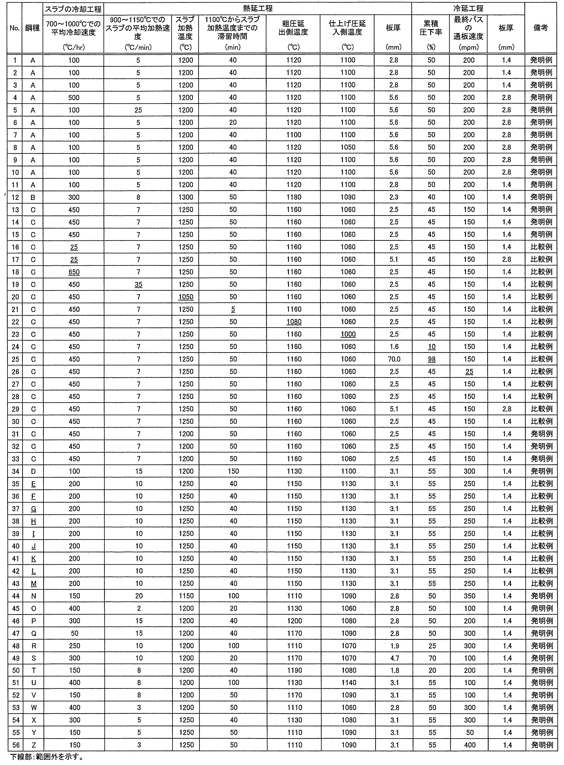
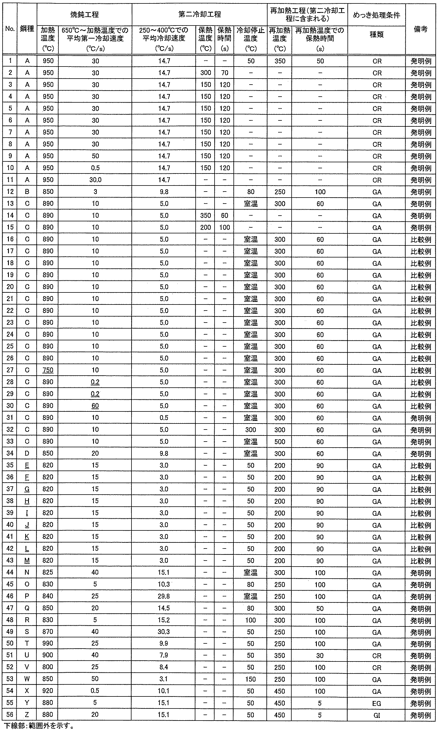
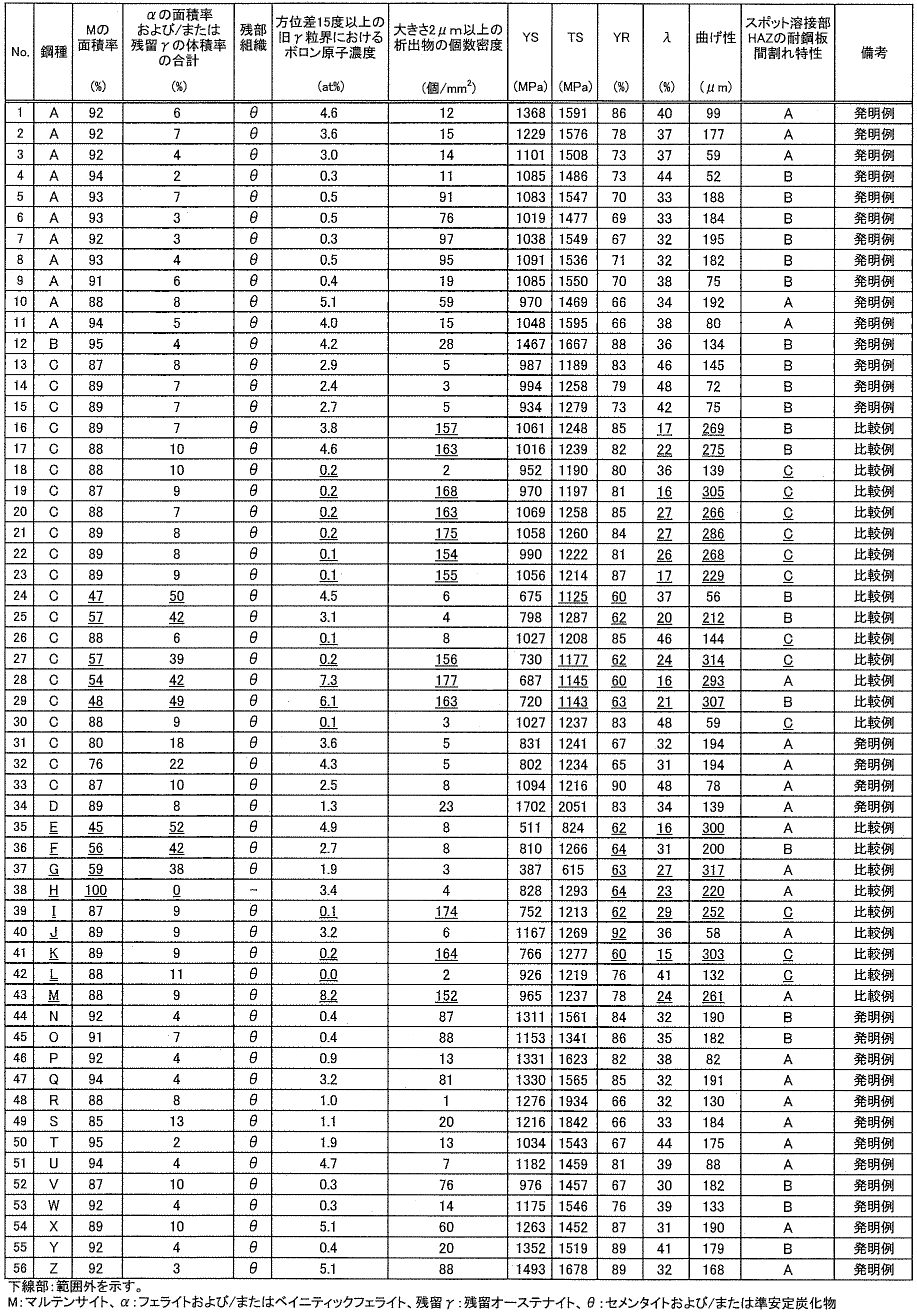
引張試験は、JIS Z 2241:2011に準拠して行った。得られた鋼板より、鋼板の圧延方向に対して直角方向となるようにJIS5号試験片を採取し、クロスヘッド速度が1.67×10⁻¹mm/sの条件で引張試験を行い、YSおよびTSを測定した。なお、本発明では、降伏比(YR)が65%以上90%以下の場合を寸法精度が高いと判断した。なお、YRは上述の式(2)に記載の計算方法で算出した。
穴広げ試験は、JIS Z 2256に準拠して行った。得られた鋼板より、100mm×100mmにせん断し、ついで、せん断した鋼板にクリアランス:12.5%で直径:10mmの穴を打ち抜いた。ついで、内径:75mmのダイスを用いてしわ押さえ力:9ton(88.26kN)で鋼板を抑え、その状態で、頂角:60°の円錐ポンチを穴に押し込んで亀裂発生限界における穴直径を測定した。そして、次式により、(限界)穴広げ率:λ(%)を求めた。
限界穴広げ率:λ(%)={(Df-D0)/D0}×100
ここで、Dfは亀裂発生時の穴径(mm)、D0は初期穴径(mm)である。そして、限界穴広げ率:λが30%以上の場合に、製造直後の伸びフランジ性に優れると判断した。
曲げ試験は、JIS Z 2248:2022に準拠して行った。得られた鋼板より、鋼板の圧延方向に対して平行方向が曲げ試験の軸方向となるように、幅が30mm、長さが100mmの短冊状の試験片を採取した。その後、押込み荷重が100kN、押付け保持時間が5秒とする条件で、90°V曲げ試験を行った。なお、本開示では、曲げ性は曲げ半径(R)を板厚(t)で除した値R/tが約4.5、即ち、4.3~4.7となるRにおいて、5サンプルの曲げ試験を実施した。次いで、5サンプル全ての曲げ頂点の稜線部におけるき裂の長さを評価し、き裂長さが200μm以下の場合、曲げ性に優れると判断した。ここで、き裂長さは、曲げ頂点の稜線部をデジタルマイクロスコープ(RH-2000:株式会社ハイロックス製)を用いて、40~160倍の倍率で測定することにより評価した。
圧延方向を長手として、板厚1.4mm、長さ30、幅100mmに切り出した試験片を、同サイズに切り出した、溶融亜鉛めっき層の片面あたりの付着量が50g/m2である試験用溶融亜鉛めっき鋼板と重ねて板組とした。次いで、サーボモータ加圧式で単相交流(50Hz)の抵抗溶接機かつ先端径が6mmの電極を用いて、該抵抗溶接機の電極に対して前記板組を5°傾け、下電極と下の鋼板の間に1.5mmのクリアランスを設けた状態で抵抗溶接を施した。具体的には、前記板組に、加圧力:3.5kN、ホールドタイム:0.16秒または0.20秒、並びにナゲット径が5.9mmになる溶接電流および溶接時間の条件にて抵抗溶接を施して溶接部付き板組とした。次いで、溶接部を含むように前記溶接部付き板組を半切して、該溶接部の断面を光学顕微鏡(200倍)で観察し、上述の基準でスポット溶接部HAZの耐鋼板間割れ特性を評価した。また、一部のサンプルでは、板厚を0.8mmおよび2.3mmで、同様の評価を実施した。
Claims (13)
- 質量%で、
C:0.030%以上0.500%以下、
Si:0.01%以上2.50%以下、
Mn:0.10%以上5.00%以下、
P:0.100%以下、
S:0.0200%以下、
Al:0.100%以下、
N:0.0100%以下、
O:0.0100%以下、
Ti:0.002%以上0.200%以下、および、
B:0.0002%以上0.0100%以下を含有するとともに、
下記(1)式から求められる有効Tiモル分率(xTi,eff)が0.001以上を満たし、
残部がFeおよび不可避的不純物からなる成分組成と、
板厚1/4位置において、
マルテンサイトの面積率が60%以上99%以下、
フェライトの面積率および/または残留オーステナイトの体積率が合計で0%超40%以下である鋼組織と、
方位差15度以上の旧オーステナイト粒界におけるボロン原子濃度が0.3at%以上6.0at%以下、
大きさ2μm以上の析出物の個数密度が150個/mm2以下である、
高強度鋼板。
記
xTi,eff=xTi-xN-xS・・・(1)
なお、式中のxTi、xN、xSは各元素の鋼板中含有量(モル分率)を表す。 - 前記成分組成は、さらに、質量%で、
Nb:0.200%以下、
V:0.200%以下、
Ta:0.10%以下、
W:0.10%以下、
Cr:1.00%以下、
Mo:1.00%以下、
Co:0.010%以下、
Ni:1.00%以下、
Cu:1.00%以下、
Sn:0.200%以下、
Sb:0.200%以下、
Ca:0.0100%以下、
Mg:0.0100%以下、
REM:0.0100%以下、
Zr:0.100%以下、
Te:0.100%以下、
Hf:0.10%以下、
Bi:0.200%以下、
のうちから選ばれる少なくとも1種の元素を含有する、請求項1に記載の高強度鋼板。 - 請求項1または2に記載の高強度鋼板の少なくとも片面にめっき層を有する、高強度めっき鋼板。
- 請求項1または2に記載の成分組成を有する鋼スラブとし、
700℃以上1000℃以下の温度域における平均冷却速度を50℃/hr以上500℃/hr以下として前記鋼スラブを冷却し、
次いで、前記鋼スラブを、900℃以上1150℃以下の温度域におけるスラブの平均加熱速度を25℃/min以下、1150℃以上のスラブ加熱温度まで、1100℃から前記スラブ加熱温度までの滞留時間を20分以上として加熱し、
次いで、前記鋼スラブに、粗圧延出側温度が1100℃以上、仕上げ圧延入側温度が1050℃以上とする熱間圧延を施して熱延板とし、
次いで、前記熱延板に酸洗を施して酸洗板とし、
次いで、前記酸洗板に、累積圧下率を20%以上95%以下、および、冷間圧延の最終パスの通板速度を50mpm以上として冷間圧延を施して冷延板とし、
次いで、前記冷延板を780℃以上の加熱温度まで加熱する焼鈍工程を行い、
次いで、前記冷延板を加熱温度から650℃までの温度域における平均冷却速度を0.5℃/s以上50℃/s以下の条件で第一冷却する、高強度鋼板の製造方法。 - 前記第一冷却の後、さらに、250℃以上400℃以下の温度域における平均冷却速度を1.0℃/s以上とする第二冷却を行う、請求項4に記載の高強度鋼板の製造方法。
- 前記第一冷却の後、さらに、100℃以上450℃以下の保熱温度で5s以上保熱する第二冷却を行う、請求項4に記載の高強度鋼板の製造方法。
- 前記第一冷却の後、さらに、冷却停止温度を250℃以下とし、次いで、前記冷延板を、(前記冷却停止温度+50℃)以上450℃以下の再加熱温度に再加熱して該再加熱温度にて5s以上保熱する第二冷却を行う、請求項4に記載の高強度鋼板の製造方法。
- 請求項4に記載の焼鈍工程の後、前記冷延板の少なくとも片面にめっき処理を施すめっき工程を行う、高強度めっき鋼板の製造方法。
- 前記第一冷却の後、さらに、250℃以上400℃以下の温度域における平均冷却速度を1.0℃/s以上とする第二冷却を行う、請求項8に記載の高強度めっき鋼板の製造方法。
- 前記第一冷却の後、さらに、100℃以上450℃以下の保熱温度で5s以上保熱する第二冷却を行う、請求項8に記載の高強度めっき鋼板の製造方法。
- 前記第一冷却の後、さらに、冷却停止温度を250℃以下とし、次いで、前記冷延板を、(前記冷却停止温度+50℃)以上450℃以下の再加熱温度に再加熱して該再加熱温度にて5s以上保熱する第二冷却を行う、請求項8に記載の高強度めっき鋼板の製造方法。
- 請求項1または2に記載の高強度鋼板を少なくとも一部に用いてなる、部材。
- 請求項3に記載の高強度めっき鋼板を少なくとも一部に用いてなる、部材。
Priority Applications (5)
| Application Number | Priority Date | Filing Date | Title |
|---|---|---|---|
| JP2024552129A JP7673875B1 (ja) | 2023-06-09 | 2024-05-16 | 高強度鋼板、高強度めっき鋼板及びそれらの製造方法並びに部材 |
| KR1020257039735A KR20260003187A (ko) | 2023-06-09 | 2024-05-16 | 고강도 강판, 고강도 도금 강판 및 그 제조 방법 그리고 부재 |
| CN202480036051.1A CN121263542A (zh) | 2023-06-09 | 2024-05-16 | 高强度钢板、高强度镀覆钢板及它们的制造方法以及构件 |
| EP24819122.3A EP4696802A4 (en) | 2023-06-09 | 2024-05-16 | HIGH-STRENGTH STEEL SHEET, HIGH-STRENGTH PLATED STEEL SHEET, THEIR MANUFACTURING PROCESSES, AND COMPONENTS |
| MX2025014480A MX2025014480A (es) | 2023-06-09 | 2025-12-02 | Lamina de acero de alta resistencia, lamina de acero con recubrimiento de alta resistencia, metodos para su fabricacion y miembro |
Applications Claiming Priority (2)
| Application Number | Priority Date | Filing Date | Title |
|---|---|---|---|
| JP2023095362 | 2023-06-09 | ||
| JP2023-095362 | 2023-06-09 |
Publications (1)
| Publication Number | Publication Date |
|---|---|
| WO2024252889A1 true WO2024252889A1 (ja) | 2024-12-12 |
Family
ID=93795351
Family Applications (1)
| Application Number | Title | Priority Date | Filing Date |
|---|---|---|---|
| PCT/JP2024/018164 Ceased WO2024252889A1 (ja) | 2023-06-09 | 2024-05-16 | 高強度鋼板、高強度めっき鋼板及びそれらの製造方法並びに部材 |
Country Status (6)
| Country | Link |
|---|---|
| EP (1) | EP4696802A4 (ja) |
| JP (1) | JP7673875B1 (ja) |
| KR (1) | KR20260003187A (ja) |
| CN (1) | CN121263542A (ja) |
| MX (1) | MX2025014480A (ja) |
| WO (1) | WO2024252889A1 (ja) |
Citations (6)
| Publication number | Priority date | Publication date | Assignee | Title |
|---|---|---|---|---|
| WO2018147400A1 (ja) * | 2017-02-13 | 2018-08-16 | Jfeスチール株式会社 | 高強度鋼板およびその製造方法 |
| JP6787535B1 (ja) | 2019-03-11 | 2020-11-18 | Jfeスチール株式会社 | 高強度鋼板およびその製造方法 |
| JP2022024998A (ja) * | 2020-07-15 | 2022-02-09 | Jfeスチール株式会社 | 高強度鋼板およびその製造方法 |
| WO2023032423A1 (ja) * | 2021-08-30 | 2023-03-09 | Jfeスチール株式会社 | 高強度鋼板,高強度めっき鋼板及びそれらの製造方法,並びに部材 |
| WO2023032424A1 (ja) * | 2021-08-30 | 2023-03-09 | Jfeスチール株式会社 | 高強度鋼板,高強度めっき鋼板及びそれらの製造方法,並びに部材 |
| WO2024053736A1 (ja) * | 2022-09-09 | 2024-03-14 | 日本製鉄株式会社 | 鋼板及びその製造方法 |
Family Cites Families (8)
| Publication number | Priority date | Publication date | Assignee | Title |
|---|---|---|---|---|
| WO2018220412A1 (fr) * | 2017-06-01 | 2018-12-06 | Arcelormittal | Procede de fabrication de pieces d'acier a haute resistance mecanique et ductilite amelioree, et pieces obtenues par ce procede |
| WO2020162561A1 (ja) * | 2019-02-06 | 2020-08-13 | 日本製鉄株式会社 | 溶融亜鉛めっき鋼板およびその製造方法 |
| WO2020225936A1 (ja) * | 2019-05-09 | 2020-11-12 | 日本製鉄株式会社 | 鋼板及びその製造方法 |
| JP6901050B1 (ja) * | 2019-07-30 | 2021-07-14 | Jfeスチール株式会社 | 高強度鋼板およびその製造方法 |
| MX428985B (es) * | 2019-09-03 | 2025-11-13 | Nippon Steel Corp | Lamina de acero |
| CN114981462B (zh) * | 2020-01-31 | 2023-11-14 | 杰富意钢铁株式会社 | 钢板、部件及其制造方法 |
| CN117529570B (zh) * | 2021-07-09 | 2026-05-26 | 杰富意钢铁株式会社 | 高强度钢板、高强度镀覆钢板及其制造方法以及构件 |
| KR20230073569A (ko) * | 2021-11-19 | 2023-05-26 | 주식회사 포스코 | 우수한 강도 및 성형성을 갖는 냉연강판 및 그 제조방법 |
-
2024
- 2024-05-16 WO PCT/JP2024/018164 patent/WO2024252889A1/ja not_active Ceased
- 2024-05-16 EP EP24819122.3A patent/EP4696802A4/en active Pending
- 2024-05-16 CN CN202480036051.1A patent/CN121263542A/zh active Pending
- 2024-05-16 JP JP2024552129A patent/JP7673875B1/ja active Active
- 2024-05-16 KR KR1020257039735A patent/KR20260003187A/ko active Pending
-
2025
- 2025-12-02 MX MX2025014480A patent/MX2025014480A/es unknown
Patent Citations (6)
| Publication number | Priority date | Publication date | Assignee | Title |
|---|---|---|---|---|
| WO2018147400A1 (ja) * | 2017-02-13 | 2018-08-16 | Jfeスチール株式会社 | 高強度鋼板およびその製造方法 |
| JP6787535B1 (ja) | 2019-03-11 | 2020-11-18 | Jfeスチール株式会社 | 高強度鋼板およびその製造方法 |
| JP2022024998A (ja) * | 2020-07-15 | 2022-02-09 | Jfeスチール株式会社 | 高強度鋼板およびその製造方法 |
| WO2023032423A1 (ja) * | 2021-08-30 | 2023-03-09 | Jfeスチール株式会社 | 高強度鋼板,高強度めっき鋼板及びそれらの製造方法,並びに部材 |
| WO2023032424A1 (ja) * | 2021-08-30 | 2023-03-09 | Jfeスチール株式会社 | 高強度鋼板,高強度めっき鋼板及びそれらの製造方法,並びに部材 |
| WO2024053736A1 (ja) * | 2022-09-09 | 2024-03-14 | 日本製鉄株式会社 | 鋼板及びその製造方法 |
Non-Patent Citations (1)
| Title |
|---|
| See also references of EP4696802A1 |
Also Published As
| Publication number | Publication date |
|---|---|
| EP4696802A4 (en) | 2026-07-29 |
| JPWO2024252889A1 (ja) | 2024-12-12 |
| EP4696802A1 (en) | 2026-02-18 |
| MX2025014480A (es) | 2026-01-07 |
| JP7673875B1 (ja) | 2025-05-09 |
| CN121263542A (zh) | 2026-01-02 |
| KR20260003187A (ko) | 2026-01-06 |
Similar Documents
| Publication | Publication Date | Title |
|---|---|---|
| US12435384B2 (en) | High-strength steel sheet and method for manufacturing same | |
| JP7044197B2 (ja) | 鋼板の製造方法及び部材の製造方法 | |
| JP7044198B2 (ja) | 鋼板の製造方法及び部材の製造方法 | |
| JP6787535B1 (ja) | 高強度鋼板およびその製造方法 | |
| JP7195501B1 (ja) | 溶融亜鉛めっき鋼板およびその製造方法、ならびに、部材 | |
| JP7239078B1 (ja) | 高強度鋼板、高強度めっき鋼板及びそれらの製造方法並びに部材 | |
| WO2024122037A1 (ja) | 高強度鋼板、高強度鋼板を用いてなる部材、部材からなる自動車の骨格構造部品用又は自動車の補強部品、ならびに高強度鋼板及び部材の製造方法 | |
| JP7673874B1 (ja) | 高強度鋼板、高強度めっき鋼板及びそれらの製造方法、ならびに、部材 | |
| KR20220144405A (ko) | 강판, 부재 및 그들의 제조 방법 | |
| KR20220144404A (ko) | 강판, 부재 및 그들의 제조 방법 | |
| JP7597270B1 (ja) | 鋼板および部材、ならびに、それらの製造方法 | |
| WO2023181641A1 (ja) | 高強度鋼板およびその製造方法 | |
| JP7673875B1 (ja) | 高強度鋼板、高強度めっき鋼板及びそれらの製造方法並びに部材 | |
| JP7193044B1 (ja) | 高強度鋼板およびその製造方法、ならびに、部材 | |
| JP7831621B2 (ja) | 溶融亜鉛めっき鋼板およびその製造方法、ならびに、部材とその製造方法、および当該部材からなる自動車の骨格構造部品又は自動車の補強部品 | |
| KR20260053079A (ko) | 강판, 부재 및 그들의 제조 방법 | |
| WO2024209605A1 (ja) | 高強度鋼板、その製造方法、部材及び自動車部品 |
Legal Events
| Date | Code | Title | Description |
|---|---|---|---|
| WWE | Wipo information: entry into national phase |
Ref document number: 2024552129 Country of ref document: JP |
|
| 121 | Ep: the epo has been informed by wipo that ep was designated in this application |
Ref document number: 24819122 Country of ref document: EP Kind code of ref document: A1 |
|
| WWE | Wipo information: entry into national phase |
Ref document number: 202517106772 Country of ref document: IN |
|
| WWE | Wipo information: entry into national phase |
Ref document number: 2024819122 Country of ref document: EP |
|
| ENP | Entry into the national phase |
Ref document number: 2024819122 Country of ref document: EP Effective date: 20251112 |
|
| ENP | Entry into the national phase |
Ref document number: 2024819122 Country of ref document: EP Effective date: 20251112 |
|
| ENP | Entry into the national phase |
Ref document number: 1020257039735 Country of ref document: KR Free format text: ST27 STATUS EVENT CODE: A-0-1-A10-A15-NAP-PA0105 (AS PROVIDED BY THE NATIONAL OFFICE) |
|
| WWE | Wipo information: entry into national phase |
Ref document number: 2501008126 Country of ref document: TH |
|
| ENP | Entry into the national phase |
Ref document number: 2024819122 Country of ref document: EP Effective date: 20251112 |
|
| WWE | Wipo information: entry into national phase |
Ref document number: MX/A/2025/014480 Country of ref document: MX |
|
| ENP | Entry into the national phase |
Ref document number: 2024819122 Country of ref document: EP Effective date: 20251112 |
|
| ENP | Entry into the national phase |
Ref document number: 2024819122 Country of ref document: EP Effective date: 20251112 |
|
| WWP | Wipo information: published in national office |
Ref document number: 202517106772 Country of ref document: IN |
|
| ENP | Entry into the national phase |
Ref document number: 2024819122 Country of ref document: EP Effective date: 20251112 |
|
| ENP | Entry into the national phase |
Ref document number: 2024819122 Country of ref document: EP Effective date: 20251112 |
|
| ENP | Entry into the national phase |
Ref document number: 2024819122 Country of ref document: EP Effective date: 20251112 |
|
| WWP | Wipo information: published in national office |
Ref document number: MX/A/2025/014480 Country of ref document: MX |
|
| NENP | Non-entry into the national phase |
Ref country code: DE |
|
| ENP | Entry into the national phase |
Ref document number: 2024819122 Country of ref document: EP Effective date: 20251112 |
|
| WWP | Wipo information: published in national office |
Ref document number: 2024819122 Country of ref document: EP |