WO2024252920A1 - 逆合成開口レーダの画像再生装置、画像再生方法および記録媒体 - Google Patents
逆合成開口レーダの画像再生装置、画像再生方法および記録媒体 Download PDFInfo
- Publication number
- WO2024252920A1 WO2024252920A1 PCT/JP2024/018657 JP2024018657W WO2024252920A1 WO 2024252920 A1 WO2024252920 A1 WO 2024252920A1 JP 2024018657 W JP2024018657 W JP 2024018657W WO 2024252920 A1 WO2024252920 A1 WO 2024252920A1
- Authority
- WO
- WIPO (PCT)
- Prior art keywords
- image
- sub
- apertures
- compression
- range
- Prior art date
- Legal status (The legal status is an assumption and is not a legal conclusion. Google has not performed a legal analysis and makes no representation as to the accuracy of the status listed.)
- Ceased
Links
Images


Classifications
-
- G—PHYSICS
- G01—MEASURING; TESTING
- G01S—RADIO DIRECTION-FINDING; RADIO NAVIGATION; DETERMINING DISTANCE OR VELOCITY BY USE OF RADIO WAVES; LOCATING OR PRESENCE-DETECTING BY USE OF THE REFLECTION OR RERADIATION OF RADIO WAVES; ANALOGOUS ARRANGEMENTS USING OTHER WAVES
- G01S13/00—Systems using the reflection or reradiation of radio waves, e.g. radar systems; Analogous systems using reflection or reradiation of waves whose nature or wavelength is irrelevant or unspecified
- G01S13/88—Radar or analogous systems specially adapted for specific applications
- G01S13/89—Radar or analogous systems specially adapted for specific applications for mapping or imaging
- G01S13/90—Radar or analogous systems specially adapted for specific applications for mapping or imaging using synthetic aperture techniques, e.g. synthetic aperture radar [SAR] techniques
- G01S13/904—SAR modes
- G01S13/9064—Inverse SAR [ISAR]
-
- G—PHYSICS
- G01—MEASURING; TESTING
- G01S—RADIO DIRECTION-FINDING; RADIO NAVIGATION; DETERMINING DISTANCE OR VELOCITY BY USE OF RADIO WAVES; LOCATING OR PRESENCE-DETECTING BY USE OF THE REFLECTION OR RERADIATION OF RADIO WAVES; ANALOGOUS ARRANGEMENTS USING OTHER WAVES
- G01S13/00—Systems using the reflection or reradiation of radio waves, e.g. radar systems; Analogous systems using reflection or reradiation of waves whose nature or wavelength is irrelevant or unspecified
- G01S13/02—Systems using reflection of radio waves, e.g. primary radar systems; Analogous systems
- G01S13/06—Systems determining position data of a target
- G01S13/08—Systems for measuring distance only
- G01S13/32—Systems for measuring distance only using transmission of continuous waves, whether amplitude-, frequency-, or phase-modulated, or unmodulated
- G01S13/34—Systems for measuring distance only using transmission of continuous waves, whether amplitude-, frequency-, or phase-modulated, or unmodulated using transmission of continuous, frequency-modulated waves while heterodyning the received signal, or a signal derived therefrom, with a locally-generated signal related to the contemporaneously transmitted signal
- G01S13/343—Systems for measuring distance only using transmission of continuous waves, whether amplitude-, frequency-, or phase-modulated, or unmodulated using transmission of continuous, frequency-modulated waves while heterodyning the received signal, or a signal derived therefrom, with a locally-generated signal related to the contemporaneously transmitted signal using sawtooth modulation
-
- G—PHYSICS
- G01—MEASURING; TESTING
- G01S—RADIO DIRECTION-FINDING; RADIO NAVIGATION; DETERMINING DISTANCE OR VELOCITY BY USE OF RADIO WAVES; LOCATING OR PRESENCE-DETECTING BY USE OF THE REFLECTION OR RERADIATION OF RADIO WAVES; ANALOGOUS ARRANGEMENTS USING OTHER WAVES
- G01S13/00—Systems using the reflection or reradiation of radio waves, e.g. radar systems; Analogous systems using reflection or reradiation of waves whose nature or wavelength is irrelevant or unspecified
- G01S13/88—Radar or analogous systems specially adapted for specific applications
- G01S13/89—Radar or analogous systems specially adapted for specific applications for mapping or imaging
- G01S13/90—Radar or analogous systems specially adapted for specific applications for mapping or imaging using synthetic aperture techniques, e.g. synthetic aperture radar [SAR] techniques
- G01S13/9004—SAR image acquisition techniques
- G01S13/9011—SAR image acquisition techniques with frequency domain processing of the SAR signals in azimuth
Definitions
- This disclosure relates to an image reproduction device, an image reproduction method, and a recording medium for an inverse synthetic aperture radar.
- Synthetic Aperture Radar is a microwave sensor mounted on satellites and aircraft that observes the Earth's surface while moving. It combines small antenna apertures to virtually form a large aperture (diameter of the radar), and improves resolution by combining the received radio waves while taking into account the Doppler effect after repeated transmission and reception.
- Inverse Synthetic Aperture Radar is known to improve resolution by using the movement and attitude change of the target (object) rather than the movement of the radar antenna, and compresses the range and azimuth of the object to image the target on the range and azimuth axes.
- SSA Space Situation Awareness
- Patent Document 1 discloses range alignment and rotation correction of high-resolution images in ISAR, in which a full-aperture data sample is received and decomposed into multiple subapertures, an ancestor image is generated for each subaperture, prominent points are selected, range alignment correction and rotation correction are performed for each ancestor image, and a phase gradient autofocus algorithm is used to correct phase errors and combine the ancestor images to generate a single high-resolution image.
- Patent Document 2 discloses an ISAR radar device that tracks a target obtained from a received signal on both the range and Doppler frequency axes to obtain the target image center, and images the target on the range and Doppler frequency axes by range compression and azimuth compression.
- the synthetic aperture length is decomposed into a time series to generate multiple ISAR images, the main axes of multiple target images are extracted, and the time change in the rotation of the main axis is observed as the rotation speed, and the image dimensions of the cross range are corrected according to the rotation speed to obtain absolute position information of the target image.
- high-resolution images can be obtained by performing range compression, azimuth compression, and various correction processes on the received signal.
- ISAR technology can convert radar signals into images, but in the case of radars that are not intended for ISAR processing, such as SSA radars, simple synthetic aperture processing cannot obtain high-resolution images when the pulse repetition frequency (PRF) is low due to the distance to the target or hardware constraints. Therefore, there is a demand for high-resolution ISAR images to be obtained using only software ingenuity, even with low-PRF radars, without the need to modify the hardware.
- PRF pulse repetition frequency
- One possible method is to simulate a received signal observed at a high PRF by upsampling and frequency shifting the received signal observed at a low PRF during image reconstruction processing.
- highly accurate observation information of the target is required.
- upsampling to the required PRF increases the amount of data in the received signal, which also increases the load on image processing.
- Patent Document 1 data samples are decomposed into multiple sub-apertures, and the resulting rough images are subjected to various corrections before being synthesized to obtain a single high-resolution image, but this does not improve the increase in image processing load.
- Patent Document 2 the center of the target image obtained from the received signal is compressed, imaged, and decomposed into a time series of synthetic aperture lengths, and the image dimensions are corrected using the rotation speed of the main axis of multiple ISAR images to calculate the absolute position of the target image, and although the target position can be observed with high accuracy, it does not obtain a high-resolution image from the received signal observed at a low PRF without increasing the image processing load. For this reason, there has been a demand for the development of technology that can reproduce high-resolution ISAR images from the received signal observed at a low PRF without increasing the calculation cost of the image reproduction process.
- the present disclosure aims to provide an image reproducing device, an image reproducing method, and a recording medium for an inverse synthetic aperture radar that solves the above-mentioned problems.
- the first aspect of the present disclosure is an image reproduction device that includes a range compression processing unit that performs range compression on a received signal obtained by observing an object with an inverse synthetic aperture radar, and an image correction processing unit that decomposes the range-compressed signal into multiple subapertures in the time direction so that adjacent subapertures partially overlap, performs azimuth compression, adds a secondary phase, and derotates for each subaperture, and then combines the multiple subapertures to perform secondary azimuth compression using the secondary phase to reproduce an image.
- a range compression processing unit that performs range compression on a received signal obtained by observing an object with an inverse synthetic aperture radar
- an image correction processing unit that decomposes the range-compressed signal into multiple subapertures in the time direction so that adjacent subapertures partially overlap, performs azimuth compression, adds a secondary phase, and derotates for each subaperture, and then combines the multiple subapertures to perform secondary azimuth compression using the secondary phase to reproduce an image
- the second aspect of the present disclosure is an image reproduction method that performs range compression on a received signal obtained by observing an object with an inverse synthetic aperture radar, decomposes the range-compressed signal into multiple subapertures in the time direction so that adjacent subapertures partially overlap, performs azimuth compression, adds a secondary phase, and derotates for each subaperture, and then combines the multiple subapertures to perform secondary azimuth compression using the secondary phase to reproduce an image.
- a third aspect of the present disclosure is a recording medium storing a program for causing a computer of an image reproducing device to perform range compression on a received signal obtained by observing an object with an inverse synthetic aperture radar, decompose the range-compressed signal into multiple subapertures in the time direction so that adjacent subapertures partially overlap, perform azimuth compression, add a secondary phase, and derotate for each subaperture, and regenerate an image by combining the multiple subapertures and performing secondary azimuth compression using the secondary phase.
- the present disclosure has the effect of enabling high-resolution ISRA images to be reconstructed from received signals observed at low PRF by an ISAR radar without increasing the image processing load.
- FIG. 1 is a block diagram of an inverse synthetic aperture image reconstruction system according to the present disclosure.
- 11 is a graph illustrating a method for splitting received data for an inverse synthetic aperture image into multiple sub-apertures according to the present disclosure.
- FIG. 2 is a block diagram of an example configuration of an ISAR image reproduction device according to the present disclosure.
- FIG. 4 is a block diagram showing details of the image correction process of the ISAR image reproduction device shown in FIG. 3.
- 1 is a flowchart for explaining an overview of ISAR image reproduction processing according to the present disclosure.
- 6 is a flowchart for explaining details of the image correction process of the ISAR image reproduction process shown in FIG. 5 .
- An image reproducing device, image reproducing method and program for an inverse synthetic aperture radar (ISAR) that transmits microwaves to a target and receives radio waves reflected from the target to generate an image will be described in detail with reference to the attached drawings, along with an embodiment of the device.
- ISR inverse synthetic aperture radar
- FIG. 1 shows the configuration of an inverse synthetic aperture image reproduction system according to the present disclosure, which is composed of an input device 10, an output device 20, and an ISAR image reproduction device 100.
- the input device 10 reads data obtained by ISAR observation, and for example, reads radio waves (reflected waves) reflected from a target when an ISAR satellite transmits microwaves to a target as a received signal.
- the ISAR image reproduction device 100 performs ISAR image processing (range compression processing, synthetic aperture processing, etc.) on the received signal from the input device 10 to reproduce an ISAR image.
- the output device 20 outputs the ISAR image reproduced by the ISAR image reproduction device to the outside.
- the ISAR image reproduction device 100 is composed of an information processing device such as a personal computer (PC), and the processor executes software (programs related to ISAR image reproduction processing) stored in memory to implement desired functions.
- the processor may be a CPU (Central Processing Unit) that controls the entire device, a GPU (Graphics Processing Unit) that performs image analysis, a GPGPU (General-Purpose GPU), a TPU (Tensor Processing Unit) that processes data, etc.
- the ISAR image reproduction device 100 implements multiple functional units 110 to 170 by the processor executing programs stored in memory, and specifically implements a range compression processing unit 110, a sub-aperture division processing unit 120, a synthetic aperture processing unit 130, a secondary phase addition processing unit 140, a de-rotation processing unit 150, a sub-aperture synthesis processing unit 160, and a secondary azimuth compression processing unit 170.
- reflected waves from a target that are spread two-dimensionally in the range and azimuth directions are compressed to a single point using pulse compression technology (compression in the range direction) and synthetic aperture technology (compression in the azimuth direction), making it possible to obtain a clear image even if the target is moving.
- the range compression processing unit 110 performs range compression of the received signal, compressing in the range direction the received signal that is the reflected waves from a target that are spread two-dimensionally in two orthogonal directions, the direction of the target's movement relative to the ISAR antenna (azimuth) and the direction in front of the antenna (range).
- the range compression processing unit 110 generates a range compressed signal.
- the sub-aperture division processing unit 120 divides the range compression signal in time by sub-aperture division processing. Specifically, the sub-aperture division processing unit 120 divides the range compression signal so that adjacent sub-apertures partially overlap, and multiplies the overlapping portion by the first half or second half of a window function (Hanning window) so that adjacent sub-apertures are smoothly connected during sub-aperture synthesis processing.
- the synthetic aperture processing unit 130 performs azimuth compression for each sub-aperture of the range compression signal by synthetic aperture processing. The azimuth compression is performed using compression parameters that are set according to the relative movement between the ISAR and the target, but the compression parameters may be set in advance by ISAR observation.
- the synthetic aperture processing unit 130 azimuth compresses the range compression signal for each sub-aperture to generate a range-azimuth compression signal.
- the secondary phase addition processing unit 140 performs secondary phase addition processing on the range-azimuth compression signal for secondary azimuth compression processing, and adds a phase that becomes a continuous linear chirp between multiple sub-apertures.
- a linear chirp changes the instantaneous frequency linearly over time, and adds an integer multiple frequency increase rate (chirp rate) to the starting frequency as time passes, and increases the frequency linearly over time between multiple sub-apertures.
- the derotation processing unit 150 performs derotation processing on the range-azimuth compression signal that has been subjected to secondary phase addition processing, and performs frequency shift processing to cancel the change in Doppler frequency (Doppler rate) of the signal from the target (target signal), and places the data frequency after derotation within the pulse repetition frequency (PRF) when the target signal is received.
- Doppler rate Doppler frequency
- PRF pulse repetition frequency
- the sub-aperture synthesis processing unit 160 synthesizes all the sub-apertures of the range-azimuth compression signal after de-rotation by the sub-aperture synthesis processing.
- the effect of the window function multiplied by the overlapping portion of adjacent sub-apertures in the sub-aperture division processing allows smooth sub-aperture synthesis by adding multiple sub-apertures.
- the secondary azimuth compression processing unit 170 performs secondary azimuth compression using the secondary phase added by the secondary phase addition processing unit 140 on the range-azimuth compression signal obtained by synthesizing multiple sub-apertures to obtain a high-resolution ISAR image.
- the ISAR image reproduction device 100 generates an ISAR reproduction image from the received signal obtained by ISAR observation.
- the output device 20 outputs the ISAR reproduction image to the outside. For example, the ISAR reproduction image is output to a subsequent information processing device, or to an external display device.
- the input device 10 inputs the received signal acquired by ISAR observation and supplies it to the ISAR image reconstruction device 100.
- the range compression processing unit 110 range-compresses the received signal related to the ISAR observation to generate a range-compressed signal.
- the sub-aperture division processing unit 120 performs sub-aperture division processing on the range-compressed signal so that the frequency band of the target signal included in the sub-aperture is equal to or less than the pulse repetition frequency (PRF) to generate multiple sub-apertures in the time domain.
- PRF pulse repetition frequency
- FIG. 2 shows a method of dividing multiple sub-apertures, in which adjacent apertures are divided so as to overlap each other, and a window function (Hanning window) is multiplied to the overlapping portion so that adjacent sub-apertures are smoothly connected in the sub-aperture synthesis processing.
- FIG. 2 shows three subapertures (Sub1 to Sub3) adjacent in the azimuth direction (Az direction) corresponding to the observation time. For example, in the overlapping portion between the rear part of subaperture Sub2 and the front part of subaperture Sub3, the rear part of subaperture Sub2 is multiplied by the Hanning window (second half), and the front part of subaperture Sub3 is multiplied by the Hanning window (first half).
- the Doppler frequency of the received signal at each time is estimated from the orbital information of the object, and the size of the sub-aperture is determined so that the bandwidth of the received signal contained in the sub-aperture is equal to or less than the pulse repetition frequency (PRF).
- PRF pulse repetition frequency
- the synthetic aperture processing unit 130 performs azimuth compression by synthetic aperture processing on the range compression signal in sub-aperture units to generate a range-azimuth compression signal.
- the secondary phase addition processing unit 140 adds a linear chirp Kscl to the range-azimuth compression signal (hereinafter referred to as signal S) in sub-aperture units.
- the secondary phase addition processing is performed in the frequency domain, and the signal S' after the secondary phase addition is expressed by the following formula 1.
- the symbol S' indicates the signal after the secondary phase addition
- the symbol S indicates the azimuth compressed signal (range-azimuth compression signal)
- the symbol Kscl indicates the linear chirp
- the symbol f ⁇ indicates the Doppler frequency.
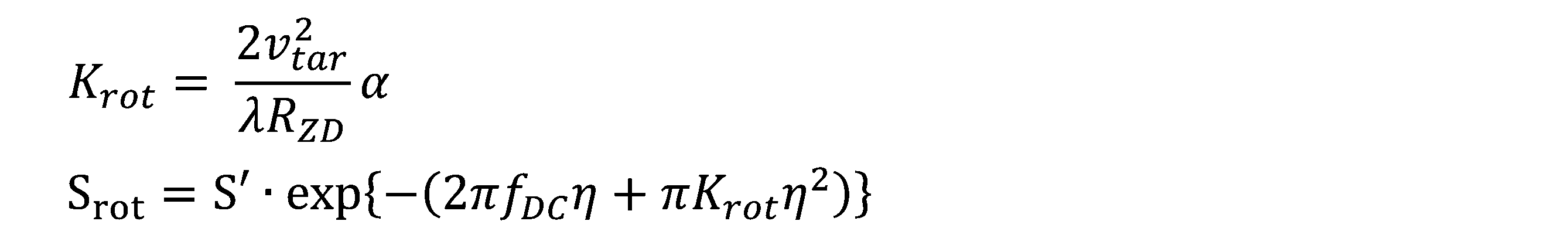
- the derotation processing unit 150 in order to fit the amount of change in the Doppler frequency of the received signal within the pulse repetition frequency (PRF) during ISAR observation, a phase rotation of the chirp K rot is performed.
- the derotation processing is performed in the time domain to generate a derotated signal S rot .
- the following formula 2 shows the chirp K rot and the derotated signal S rot .
- the symbol S' indicates the signal after the secondary phase is added
- the symbol S rot indicates the signal after derotation
- the symbol v tar indicates the target speed
- the symbol ⁇ indicates the carrier wavelength
- the symbol R ZD indicates the target distance at zero Doppler
- the symbol f DC indicates the Doppler frequency at the observation center time
- the symbol ⁇ indicates the time based on zero Doppler
- the symbol ⁇ indicates the derotation parameter.
- the de-rotation parameter ⁇ assumes that the target is a point, but in practice it is desirable to add a margin of several percent to several tens of percent to the bandwidth of the target signal.
- the sub-aperture synthesis processing unit 160 performs sub-aperture synthesis processing by adding all the sub-apertures in the time domain.
- the secondary azimuth compression processing unit 170 performs a fast Fourier transform (FFT) on the signal after the sub-aperture synthesis, performs azimuth compression using a reference signal S ref of the chirp K eff , and finally performs an inverse FFT to generate an ISAR image.
- FFT fast Fourier transform
- the following Equation 3 shows the chirp K eff and the reference signal S ref , where the symbol f ⁇ indicates the Doppler frequency, the symbol K scl indicates the linear chirp, and the symbol K rot indicates the chirp used in the de-rotation.
- the output device 20 outputs the ISAR image reconstructed by the ISAR image reconstruction device 100.
- FIG. 3 is a block diagram showing the functions of a configuration example of an ISAR image reproduction device 200 according to the present disclosure, which executes a range compression process 210 and an image correction process 220.
- range compression process 210 range compression is performed on the received signal by ISAR observation.
- the image correction process 220 is the core of some embodiments of the present disclosure, and performs image correction on the received signal after range compression.
- the image correction includes azimuth compression for each subaperture, secondary phase addition, and de-rotation, and after all the subapertures are synthesized, secondary azimuth compression using the secondary phase is performed. This makes it possible to reproduce a high-resolution ISAR image even in the case of radar observation with a low PRF.
- FIG. 4 is a block diagram showing the detailed functions of the image correction process 220.
- the received signal after range compression is divided into multiple sub-apertures in the time direction by sub-aperture division 230.
- synthetic aperture processing (azimuth compression) 240, secondary phase addition 250, and de-rotation 260 are performed for each sub-aperture, and all the sub-apertures are synthesized into one by sub-aperture synthesis 270.
- the received signal after sub-aperture synthesis is subjected to secondary azimuth compression 280 using the secondary phase, and an ISAR image is generated.
- FIG. 5 is a flowchart for explaining an example of the function according to the present disclosure, and corresponds to the configuration example of FIG. 3.
- a range compression process (S10) and an image correction process (S20) are executed.
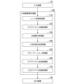
- FIG. 6 is a flowchart for explaining details of the image correction process (S20), which is a core function of some embodiments of the present disclosure.
- the received signal after range compression is decomposed into a plurality of sub-apertures in the time direction (S21), and then image correction is performed (S22). In the image correction, azimuth compression, secondary phase addition, and de-rotation are performed for each sub-aperture.
- the plurality of sub-apertures are combined into one (S23), and secondary azimuth compression using the secondary phase is performed (S24).
- the present disclosure is characterized in that azimuth compression, secondary phase addition, and de-rotation are performed for each sub-aperture on the received signal after range compression.
- a linear chirp K scl is added to the azimuth-compressed signal S for each sub-aperture to convert it into a signal S'.
- derotation as shown in Equation 2, a phase rotation of a chirp K rot is performed to convert a signal S' into a derotated signal S rot .
- a derotation parameter ⁇ is set to fit a derotated target signal within the PRF.
- the ISAR image reproduction device 200 implements the above-mentioned functions by having a processor (CPU, GPU, etc.) execute a range compression program, an image correction program, etc., but the computer program may be stored in a storage medium (semiconductor memory such as ROM or RAM), or may be distributed from another device.
- the computer program may be for realizing part of the above-mentioned functions, or may be a so-called difference file (or difference program) that can realize the above-mentioned functions in combination with a program already recorded in the computer system.
- the present disclosure is characterized in that, in image processing of an inverse synthetic aperture radar (ISAR), a received signal acquired at a pulse repetition frequency (PRF) less than the Nyquist frequency is divided in the time direction to generate multiple subapertures, and synthetic aperture processing (azimuth compression), secondary phase addition (linear chirp addition), and de-rotation are performed for each subaperture, and finally all the subapertures are synthesized.
- ISR inverse synthetic aperture radar
- PRF pulse repetition frequency
- de-rotation de-rotation
- the Nyquist frequency means a frequency that is half the sampling frequency in the sampling theorem, but is not limited to this, and is a frequency that satisfies the Nyquist condition for reproducing the original signal when a specific signal group is sampled and reproduced.
- the present disclosure is not limited to the above-described embodiment, and the configuration and functions of the ISAR image reproduction device are not limited to those shown in Figs. 1 to 6.
- the present disclosure does not limit the synthetic aperture processing, and is applicable regardless of the synthetic aperture processing method.
- the window function multiplied to the multiple subapertures in the subaperture division processing is not limited to the Hanning window, and any window function that can smoothly connect the overlapping parts of adjacent subapertures when synthesizing the subapertures can be applied.
- multiple subapertures may be synthesized by using half of the overlapping parts of each subaperture without multiplying the multiple subapertures by a window function.
- a received signal acquired at a low PRF in ISAR observation (such as a reflected wave received by irradiating a target, such as a space object or an object on the Earth's surface, with a microwave) is divided into multiple sub-apertures in the time direction (azimuth direction), synthetic aperture processing is performed for each sub-aperture, and then the multiple sub-apertures are synthesized, thereby making it possible to reproduce a high-resolution ISAR image.
- the division is performed so that the Doppler frequency of the target signal (such as the reflected wave from the target) does not exceed the PRF at the time of observation.
- the accuracy of the target trajectory information is low, the amount of data to be included in the sub-aperture (or the size of the sub-aperture) is reduced according to the uncertainty of the target, so that the image reconstruction process can be continued.
- the image reproducing device includes a range compression processing unit that performs range compression on a received signal obtained by observing an object with an inverse synthetic aperture radar, and an image correction processing unit that decomposes the range-compressed signal into a plurality of subapertures in the time direction so that adjacent subapertures partially overlap, performs azimuth compression, adds a secondary phase, and de-rotates for each subaperture, and then combines the plurality of subapertures and performs secondary azimuth compression using the secondary phase to reproduce an image.
- the image correction processing unit may apply a window function to an overlapping portion between adjacent sub-apertures among the multiple sub-apertures.
- the image correction processing unit may add a first chirp to the signal after azimuth compression by adding a quadratic phase.
- the image correction processing unit may perform a phase rotation of a second chirp on the signal to which a quadratic phase has been added by de-rotation.
- the image correction processing unit may perform secondary azimuth compression on the signal obtained after combining the multiple sub-apertures by using a reference signal including a third chirp that corresponds to the difference between the first chirp and the second chirp.
- the present disclosure also includes an image reproduction method and a recording medium storing a program.
- the image reconstruction method performs range compression on a received signal obtained by observing an object with an inverse synthetic aperture radar, decomposes the range-compressed signal into a plurality of subapertures in the time direction so that adjacent subapertures partially overlap, performs azimuth compression, adds a secondary phase, and de-rotates for each subaperture, and reconstructs an image by combining the plurality of subapertures and performing secondary azimuth compression using the secondary phase.
- the recording medium stores a program for causing a computer of the image reproducing device to perform range compression on a received signal obtained by observing an object by an inverse synthetic aperture radar, decomposing the range-compressed signal into a plurality of subapertures in the time direction so that adjacent subapertures partially overlap, performing azimuth compression, adding a secondary phase, and de-rotation for each subaperture, and combining the plurality of subapertures to perform secondary azimuth compression using the secondary phase, thereby reproducing an image.
- This disclosure relates to an inverse synthetic aperture radar (ISAR) that receives reflected waves of microwaves irradiated on an object and performs image correction processing such as range compression and azimuth compression to reproduce ISAR images, but the scope of application is not limited to the observation of space conditions of space objects (such as space debris), and can also be applied to the observation of surface structures (such as oil tanks), ships, the observation of subsidence in specific areas on the ground, and the observation of environmental destruction such as water source pollution and deforestation.
- ISR inverse synthetic aperture radar
Landscapes
- Engineering & Computer Science (AREA)
- Remote Sensing (AREA)
- Radar, Positioning & Navigation (AREA)
- Physics & Mathematics (AREA)
- Computer Networks & Wireless Communication (AREA)
- General Physics & Mathematics (AREA)
- Electromagnetism (AREA)
- Signal Processing (AREA)
- Radar Systems Or Details Thereof (AREA)
Abstract
Description


(1)本開示では、ISAR観測において低PRFで取得された受信信号(宇宙物体や地表上の物体などのターゲットにマイクロ波を照射して受信した反射波など)を時間方向(アジマス方向)に複数のサブアパチャに分割し、サブアパチャ毎に合成開口処理を行った後に複数のサブアパチャを合成することにより、高分解能なISAR画像を再生することができる。
(2)時間方向の複数のサブアパチャへの分割では、ターゲット信号(ターゲットからの反射波など)の有するドップラ周波数が観測時のPRFを超えないように分割する。ターゲットの軌道情報の精度が低い場合、ターゲットの不定性に応じてサブアパチャに含めるデータ量を減らす(或いは、サブアパチャのサイズを小さくする)ことにより、画像再生処理を継続することができる。
(3)低PRFのレーダによる観測時において、観測対象のターゲットの高精度な軌道情報が得られない場合でも、サブアパチャ単位での合成開口処理およびターゲットの軌道精度に依存しない二次位相(線形チャープ)によるアジマス圧縮処理を行うことによって、ハードウェアの改修をすることなく高分解能なISAR再生画像を得ることができる。
(4)本開示では受信信号のアップサンプル(サンプリング周波数の増加)を含んでおらず、低PRFの受信信号のままで画像再生処理を行うことができ、アップサンプルによる計算負荷の増大を回避するとともに、画像再生処理の計算コストの増大も防ぐことができる。
(付記1)画像再生装置は、逆合成開口レーダによる対象物の観測によって得られた受信信号についてレンジ圧縮を行うレンジ圧縮処理部と、レンジ圧縮後の信号を隣接するサブアパチャが部分的に重複するように時間方向に複数のサブアパチャに分解し、サブアパチャ毎にアジマス圧縮、二次位相の付加、デローテーションを行った後、複数のサブアパチャを合成して二次位相を用いた二次アジマス圧縮を行って画像を再生する画像補正処理部と、を具備する。
(付記2)画像補正処理部は、複数のサブアパチャにおいて隣接するサブアパチャの重複部には窓関数を適用してもよい。
(付記3)画像補正処理部は、二次位相の付加にてアジマス圧縮後の信号に対して第1のチャープを付加してもよい。
(付記4)画像補正処理部は、デローテーションにて二次位相の付加後の信号に対して第2のチャープの位相回転を行ってもよい。
(付記5)画像補正処理部は、複数のサブアパチャの合成後の信号に対して第1のチャープと第2のチャープの差に相当する第3のチャープを含む参照信号を用いて二次アジマス圧縮を行ってもよい。
(付記6)画像再生方法は、逆合成開口レーダによる対象物の観測によって得られた受信信号についてレンジ圧縮を行い、レンジ圧縮後の信号を隣接するサブアパチャが部分的に重複するように時間方向に複数のサブアパチャに分解し、サブアパチャ毎にアジマス圧縮、二次位相の付加、デローテーションを行い、複数のサブアパチャを合成して二次位相を用いた二次アジマス圧縮を行って画像を再生する。
(付記7)記録媒体は、画像再生装置のコンピュータに、逆合成開口レーダによる対象物の観測によって得られた受信信号についてレンジ圧縮を行い、レンジ圧縮後の信号を隣接するサブアパチャが部分的に重複するように時間方向に複数のサブアパチャに分解し、サブアパチャ毎にアジマス圧縮、二次位相の付加、デローテーションを行い、複数のサブアパチャを合成して二次位相を用いた二次アジマス圧縮を行って画像を再生する、ことを実行させるためのプログラムを記憶する。
20 出力装置
100、200 ISAR画像再生装置
110 レンジ圧縮処理部
120 サブアパチャ分割処理部
130 合成開口処理部
140 二次位相付加処理部
150 デローテーション処理部
160 サブアパチャ合成処理部
170 二次アジマス圧縮処理部
210 レンジ圧縮処理
220 画像補正処理
230 サブアパチャ分割
240 合成開口処理(アジマス圧縮)
250 二次位相付加
260 デローテーション
270 サブアパチャ合成
280 二次アジマス圧縮
Claims (7)
- 逆合成開口レーダによる対象物の観測によって得られた受信信号についてレンジ圧縮を行うレンジ圧縮処理部と、
前記レンジ圧縮後の信号を隣接するサブアパチャが部分的に重複するように時間方向に複数のサブアパチャに分解し、サブアパチャ毎にアジマス圧縮、二次位相の付加、デローテーションを行った後、前記複数のサブアパチャを合成して前記二次位相を用いた二次アジマス圧縮を行って画像を再生する画像補正処理部と、
を具備する画像再生装置。 - 前記画像補正処理部において、前記複数のサブアパチャにおいて隣接するサブアパチャの重複部分には窓関数を適用するようにした、請求項1に記載の画像再生装置。
- 前記画像補正処理部において、前記二次位相の付加では前記アジマス圧縮後の信号に対して第1のチャープを付加する、請求項1に記載の画像再生装置。
- 前記画像補正処理部において、前記デローテーションでは前記二次位相の付加後の信号に対して第2のチャープの位相回転を行う、請求項3に記載の画像再生装置。
- 前記画像補正処理部において、前記複数のサブアパチャの合成後の信号に対して前記第1のチャープと前記第2のチャープの差に相当する第3のチャープを含む参照信号を用いて前記二次アジマス圧縮を行う、請求項4に記載の画像再生装置。
- 逆合成開口レーダによる対象物の観測によって得られた受信信号についてレンジ圧縮を行い、
前記レンジ圧縮後の信号を隣接するサブアパチャが部分的に重複するように時間方向に複数のサブアパチャに分解し、
サブアパチャ毎にアジマス圧縮、二次位相の付加、デローテーションを行い、
前記複数のサブアパチャを合成して前記二次位相を用いた二次アジマス圧縮を行って画像を再生する、
画像再生方法。 - 画像再生装置のコンピュータに、
逆合成開口レーダによる対象物の観測によって得られた受信信号についてレンジ圧縮を行い、
前記レンジ圧縮後の信号を隣接するサブアパチャが部分的に重複するように時間方向に複数のサブアパチャに分解し、
サブアパチャ毎にアジマス圧縮、二次位相の付加、デローテーションを行い、
前記複数のサブアパチャを合成して前記二次位相を用いた二次アジマス圧縮を行って画像を再生する、
ことを実行させるためのプログラムを記憶した記録媒体。
Priority Applications (2)
| Application Number | Priority Date | Filing Date | Title |
|---|---|---|---|
| EP24819153.8A EP4718116A1 (en) | 2023-06-09 | 2024-05-21 | Image reproduction device for inverse synthetic aperture radar, image reproduction method, and recording medium |
| JP2025526041A JPWO2024252920A5 (ja) | 2024-05-21 | 画像再生装置、画像再生方法およびプログラム |
Applications Claiming Priority (2)
| Application Number | Priority Date | Filing Date | Title |
|---|---|---|---|
| JP2023095429 | 2023-06-09 | ||
| JP2023-095429 | 2023-06-09 |
Publications (1)
| Publication Number | Publication Date |
|---|---|
| WO2024252920A1 true WO2024252920A1 (ja) | 2024-12-12 |
Family
ID=93795470
Family Applications (1)
| Application Number | Title | Priority Date | Filing Date |
|---|---|---|---|
| PCT/JP2024/018657 Ceased WO2024252920A1 (ja) | 2023-06-09 | 2024-05-21 | 逆合成開口レーダの画像再生装置、画像再生方法および記録媒体 |
Country Status (2)
| Country | Link |
|---|---|
| EP (1) | EP4718116A1 (ja) |
| WO (1) | WO2024252920A1 (ja) |
Cited By (1)
| Publication number | Priority date | Publication date | Assignee | Title |
|---|---|---|---|---|
| CN121746255A (zh) * | 2026-02-28 | 2026-03-27 | 国家卫星海洋应用中心 | 合成孔径雷达影像的校正方法、装置、设备及程序产品 |
Citations (6)
| Publication number | Priority date | Publication date | Assignee | Title |
|---|---|---|---|---|
| US5343204A (en) * | 1993-07-29 | 1994-08-30 | Unisys Corporation | Auto-focusing correction for rotational acceleration effects on inverse synthetic aperture radar images |
| US6255981B1 (en) | 1999-08-04 | 2001-07-03 | Raytheon Company | Method for range alignment and rotation correction of a high resolution image in an inverse synthetic aperture radar system |
| JP2017003494A (ja) | 2015-06-12 | 2017-01-05 | 株式会社東芝 | レーダ装置及びレーダ信号処理方法 |
| WO2017195297A1 (ja) * | 2016-05-11 | 2017-11-16 | 三菱電機株式会社 | レーダ処理装置 |
| JP2023095429A (ja) | 2021-12-24 | 2023-07-06 | 東洋紡株式会社 | 生体試料中のエストロンを定量するためのイムノクロマト測定キット |
| JP2023180643A (ja) * | 2022-06-10 | 2023-12-21 | 日本電気株式会社 | 逆合成開口レーダ画像処理装置、逆合成開口レーダ画像処理方法および逆合成開口レーダ画像処理プログラム |
-
2024
- 2024-05-21 EP EP24819153.8A patent/EP4718116A1/en active Pending
- 2024-05-21 WO PCT/JP2024/018657 patent/WO2024252920A1/ja not_active Ceased
Patent Citations (6)
| Publication number | Priority date | Publication date | Assignee | Title |
|---|---|---|---|---|
| US5343204A (en) * | 1993-07-29 | 1994-08-30 | Unisys Corporation | Auto-focusing correction for rotational acceleration effects on inverse synthetic aperture radar images |
| US6255981B1 (en) | 1999-08-04 | 2001-07-03 | Raytheon Company | Method for range alignment and rotation correction of a high resolution image in an inverse synthetic aperture radar system |
| JP2017003494A (ja) | 2015-06-12 | 2017-01-05 | 株式会社東芝 | レーダ装置及びレーダ信号処理方法 |
| WO2017195297A1 (ja) * | 2016-05-11 | 2017-11-16 | 三菱電機株式会社 | レーダ処理装置 |
| JP2023095429A (ja) | 2021-12-24 | 2023-07-06 | 東洋紡株式会社 | 生体試料中のエストロンを定量するためのイムノクロマト測定キット |
| JP2023180643A (ja) * | 2022-06-10 | 2023-12-21 | 日本電気株式会社 | 逆合成開口レーダ画像処理装置、逆合成開口レーダ画像処理方法および逆合成開口レーダ画像処理プログラム |
Non-Patent Citations (2)
| Title |
|---|
| MARCHETTI EMIDIO, STOVE ANDREW G., HOARE EDWARD G., CHERNIAKOV MIKHAIL, BLACKNELL DAVID, GASHINOVA MARINA: "Space-Based Sub-THz ISAR for Space Situational Awareness—Concept and Design", IEEE TRANSACTIONS ON AEROSPACE AND ELECTRONIC SYSTEMS., IEEE SERVICE CENTER, PISCATAWAY, NJ., US, vol. 58, no. 3, 1 June 2022 (2022-06-01), US , pages 1558 - 1573, XP093246477, ISSN: 0018-9251, DOI: 10.1109/TAES.2021.3126375 * |
| NOVIELLO CARLO, FORNARO GIANFRANCO, BRACA PAOLO, MARTORELLA MARCO: "Fast and Accurate ISAR Focusing Based on a Doppler Parameter Estimation Algorithm", IEEE GEOSCIENCE AND REMOTE SENSING LETTERS, IEEE, USA, vol. 14, no. 3, 1 March 2017 (2017-03-01), USA, pages 349 - 353, XP093246472, ISSN: 1545-598X, DOI: 10.1109/LGRS.2016.2641498 * |
Cited By (1)
| Publication number | Priority date | Publication date | Assignee | Title |
|---|---|---|---|---|
| CN121746255A (zh) * | 2026-02-28 | 2026-03-27 | 国家卫星海洋应用中心 | 合成孔径雷达影像的校正方法、装置、设备及程序产品 |
Also Published As
| Publication number | Publication date |
|---|---|
| EP4718116A1 (en) | 2026-04-01 |
| JPWO2024252920A1 (ja) | 2024-12-12 |
Similar Documents
| Publication | Publication Date | Title |
|---|---|---|
| US7397418B1 (en) | SAR image formation with azimuth interpolation after azimuth transform | |
| Ausherman et al. | Developments in radar imaging | |
| Zhang et al. | Synthetic aperture image enhancement with near-coinciding nonuniform sampling case | |
| CN111505639A (zh) | 基于变重频采样模式的合成孔径雷达宽幅稀疏成像方法 | |
| CN111781595B (zh) | 基于匹配搜索和多普勒解模糊的复杂机动群目标成像方法 | |
| CN110187347B (zh) | 一种地球同步轨道星机双基合成孔径雷达大幅宽成像方法 | |
| Zhang et al. | LBF-based CS algorithm for multireceiver SAS | |
| JPH0646405B2 (ja) | 合成開口レ−ダ画像再生処理方法 | |
| KR101839041B1 (ko) | 연속 이동 효과 보정 기법을 이용하는 fmcw-sar 시스템 및 이 시스템의 sar 영상 복원 방법 | |
| CN116930966B (zh) | Staggered SAR体制下三维摆动舰船目标成像重建方法 | |
| Pu et al. | Fast compressive sensing-based SAR imaging integrated with motion compensation | |
| Liang et al. | Processing of very high resolution GF-3 SAR spotlight data with non-start–stop model and correction of curved orbit | |
| US7301495B2 (en) | Interrupt SAR implementation for range migration (RMA) processing | |
| JP2011169869A (ja) | レーダ信号処理装置 | |
| WO2024252920A1 (ja) | 逆合成開口レーダの画像再生装置、画像再生方法および記録媒体 | |
| JP5106323B2 (ja) | レーダ画像再生装置 | |
| JP3695103B2 (ja) | レーダ信号処理装置 | |
| Önhon et al. | A nonquadratic regularization-based technique for joint SAR imaging and model error correction | |
| Li et al. | An improved ultrahigh-resolution stepped-frequency spaceborne SAR imaging algorithm | |
| Önhon et al. | SAR moving target imaging in a sparsity-driven framework | |
| CN118330636A (zh) | 一种星载毫米波视频sar快速成像处理方法及处理系统 | |
| Chen et al. | A data-driven motion compensation scheme for compressed sensing SAR image restoration | |
| Chen et al. | A motion compensation scheme for compressed sensing SAR image restoration using measured antenna phase center data | |
| Qian et al. | Modified generalized omega-K algorithm for low earth orbit high resolution spotlight spaceborne SAR focusing | |
| Jylhä et al. | On SAR processing using pixel-wise matched kernels |
Legal Events
| Date | Code | Title | Description |
|---|---|---|---|
| 121 | Ep: the epo has been informed by wipo that ep was designated in this application |
Ref document number: 24819153 Country of ref document: EP Kind code of ref document: A1 |
|
| ENP | Entry into the national phase |
Ref document number: 2025526041 Country of ref document: JP Kind code of ref document: A |
|
| WWE | Wipo information: entry into national phase |
Ref document number: 202517122738 Country of ref document: IN |
|
| WWE | Wipo information: entry into national phase |
Ref document number: 2024819153 Country of ref document: EP |
|
| WWP | Wipo information: published in national office |
Ref document number: 202517122738 Country of ref document: IN |
|
| ENP | Entry into the national phase |
Ref document number: 2024819153 Country of ref document: EP Effective date: 20251224 |
|
| ENP | Entry into the national phase |
Ref document number: 2024819153 Country of ref document: EP Effective date: 20251224 |
|
| NENP | Non-entry into the national phase |
Ref country code: DE |
|
| ENP | Entry into the national phase |
Ref document number: 2024819153 Country of ref document: EP Effective date: 20251224 |
|
| ENP | Entry into the national phase |
Ref document number: 2024819153 Country of ref document: EP Effective date: 20251224 |
|
| ENP | Entry into the national phase |
Ref document number: 2024819153 Country of ref document: EP Effective date: 20251224 |
|
| ENP | Entry into the national phase |
Ref document number: 2024819153 Country of ref document: EP Effective date: 20251224 |
|
| ENP | Entry into the national phase |
Ref document number: 2024819153 Country of ref document: EP Effective date: 20251224 |
|
| WWP | Wipo information: published in national office |
Ref document number: 2024819153 Country of ref document: EP |