WO2024252928A1 - High-frequency treatment device and high-frequency treatment method - Google Patents
High-frequency treatment device and high-frequency treatment method Download PDFInfo
- Publication number
- WO2024252928A1 WO2024252928A1 PCT/JP2024/018824 JP2024018824W WO2024252928A1 WO 2024252928 A1 WO2024252928 A1 WO 2024252928A1 JP 2024018824 W JP2024018824 W JP 2024018824W WO 2024252928 A1 WO2024252928 A1 WO 2024252928A1
- Authority
- WO
- WIPO (PCT)
- Prior art keywords
- frequency
- connection state
- electrodes
- electrode
- unit
- Prior art date
- Legal status (The legal status is an assumption and is not a legal conclusion. Google has not performed a legal analysis and makes no representation as to the accuracy of the status listed.)
- Ceased
Links
Images




Classifications
-
- A—HUMAN NECESSITIES
- A61—MEDICAL OR VETERINARY SCIENCE; HYGIENE
- A61B—DIAGNOSIS; SURGERY; IDENTIFICATION
- A61B18/00—Surgical instruments, devices or methods for transferring non-mechanical forms of energy to or from the body
- A61B18/04—Surgical instruments, devices or methods for transferring non-mechanical forms of energy to or from the body by heating
- A61B18/12—Surgical instruments, devices or methods for transferring non-mechanical forms of energy to or from the body by heating by passing a current through the tissue to be heated, e.g. high-frequency current
- A61B18/14—Probes or electrodes therefor
- A61B18/1477—Needle-like probes
-
- A—HUMAN NECESSITIES
- A61—MEDICAL OR VETERINARY SCIENCE; HYGIENE
- A61B—DIAGNOSIS; SURGERY; IDENTIFICATION
- A61B18/00—Surgical instruments, devices or methods for transferring non-mechanical forms of energy to or from the body
- A61B18/04—Surgical instruments, devices or methods for transferring non-mechanical forms of energy to or from the body by heating
- A61B18/12—Surgical instruments, devices or methods for transferring non-mechanical forms of energy to or from the body by heating by passing a current through the tissue to be heated, e.g. high-frequency current
- A61B18/1206—Generators therefor
-
- A—HUMAN NECESSITIES
- A61—MEDICAL OR VETERINARY SCIENCE; HYGIENE
- A61B—DIAGNOSIS; SURGERY; IDENTIFICATION
- A61B18/00—Surgical instruments, devices or methods for transferring non-mechanical forms of energy to or from the body
- A61B2018/00053—Mechanical features of the instrument of device
- A61B2018/0016—Energy applicators arranged in a two- or three dimensional array
-
- A—HUMAN NECESSITIES
- A61—MEDICAL OR VETERINARY SCIENCE; HYGIENE
- A61B—DIAGNOSIS; SURGERY; IDENTIFICATION
- A61B18/00—Surgical instruments, devices or methods for transferring non-mechanical forms of energy to or from the body
- A61B2018/00315—Surgical instruments, devices or methods for transferring non-mechanical forms of energy to or from the body for treatment of particular body parts
- A61B2018/00434—Neural system
-
- A—HUMAN NECESSITIES
- A61—MEDICAL OR VETERINARY SCIENCE; HYGIENE
- A61B—DIAGNOSIS; SURGERY; IDENTIFICATION
- A61B18/00—Surgical instruments, devices or methods for transferring non-mechanical forms of energy to or from the body
- A61B2018/00571—Surgical instruments, devices or methods for transferring non-mechanical forms of energy to or from the body for achieving a particular surgical effect
- A61B2018/00577—Ablation
-
- A—HUMAN NECESSITIES
- A61—MEDICAL OR VETERINARY SCIENCE; HYGIENE
- A61B—DIAGNOSIS; SURGERY; IDENTIFICATION
- A61B18/00—Surgical instruments, devices or methods for transferring non-mechanical forms of energy to or from the body
- A61B2018/00636—Sensing and controlling the application of energy
- A61B2018/00773—Sensed parameters
- A61B2018/00875—Resistance or impedance
-
- A—HUMAN NECESSITIES
- A61—MEDICAL OR VETERINARY SCIENCE; HYGIENE
- A61B—DIAGNOSIS; SURGERY; IDENTIFICATION
- A61B18/00—Surgical instruments, devices or methods for transferring non-mechanical forms of energy to or from the body
- A61B18/04—Surgical instruments, devices or methods for transferring non-mechanical forms of energy to or from the body by heating
- A61B18/12—Surgical instruments, devices or methods for transferring non-mechanical forms of energy to or from the body by heating by passing a current through the tissue to be heated, e.g. high-frequency current
- A61B18/1206—Generators therefor
- A61B2018/124—Generators therefor switching the output to different electrodes, e.g. sequentially
-
- A—HUMAN NECESSITIES
- A61—MEDICAL OR VETERINARY SCIENCE; HYGIENE
- A61B—DIAGNOSIS; SURGERY; IDENTIFICATION
- A61B18/00—Surgical instruments, devices or methods for transferring non-mechanical forms of energy to or from the body
- A61B18/04—Surgical instruments, devices or methods for transferring non-mechanical forms of energy to or from the body by heating
- A61B18/12—Surgical instruments, devices or methods for transferring non-mechanical forms of energy to or from the body by heating by passing a current through the tissue to be heated, e.g. high-frequency current
- A61B18/14—Probes or electrodes therefor
- A61B2018/1405—Electrodes having a specific shape
- A61B2018/1425—Needle
- A61B2018/143—Needle multiple needles
Definitions
- the present invention relates to a high-frequency treatment device and a high-frequency treatment method that perform various treatments by passing a high-frequency current through a treatment target.
- Radiofrequency thermocoagulation uses a radiofrequency current flowing from an electrode to heat part of the nerve tissue to a temperature of around 80°C for several minutes, causing it to thermally coagulate, thereby blocking pain signals.
- Pulsed radiofrequency uses a continuous flow of radiofrequency current through part of the nerve tissue, heating it to a temperature of 42°C or less for about 10 minutes, blocking pain signals without damaging the nerves.
- the present invention aims to provide a high-frequency treatment device and a high-frequency treatment method that can efficiently heat a wide area.
- the high-frequency treatment device of the present invention is characterized by having a plurality of high-frequency output units that output high-frequency power, a plurality of electrodes that are connected to the high-frequency output units and placed on a treatment target, a switching unit that is provided between the high-frequency output units and the electrodes and that switches which of the electrode sets each consisting of at least two of the electrodes to which a high-frequency current flows, and a control unit that controls the switching unit to switch, at a specific period, between a first connection state in which a different electrode set is connected to each of the high-frequency output units during treatment and a second connection state in which an electrode set formed by combining the plurality of electrode sets in the first connection state is connected to one of the high-frequency output units.
- the high-frequency treatment method of the present invention is a high-frequency treatment method in which a plurality of electrodes are placed on a treatment target, and a high-frequency current is passed from a plurality of high-frequency output units to any one of the electrode sets, each of which is a combination of at least two of the electrodes, to perform treatment, and is characterized in that during treatment, a first connection state in which a different electrode set is connected to each of the high-frequency output units and a second connection state in which an electrode set formed by combining the plurality of electrode sets in the first connection state is connected to one of the high-frequency output units are switched at a specific period.
- the high-frequency treatment device and method of the present invention allow the heating state in the first connection state and the heating state in the second connection state to complement each other's less heated areas, making it possible to efficiently heat a wide area.
- the second connection state is a connection state in which the electrodes included in the same electrode group in the first connection state have the same polarity.
- the second connection state is a connection state in which the electrode set including all of the electrodes is connected to one of the high-frequency output sections.
- the high-frequency treatment device of the present invention preferably has an impedance measuring unit that is connected to the electrodes via the switching unit and measures impedance by outputting an impedance measurement signal, and the control unit controls the switching unit to provide a third connection state between the first connection state and the second connection state in which the electrode set is connected to the impedance measuring unit.
- this stop period can be utilized to perform highly accurate impedance measurements using a dedicated impedance measuring unit, making it possible to efficiently heat a wide area.
- the high-frequency treatment device and method of the present invention have the excellent effect of being able to efficiently heat a wide area.
- 1 is a schematic diagram showing the appearance of a high-frequency treatment device according to an embodiment of the present invention
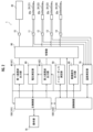
- 1 is a block diagram showing an outline of the internal configuration of a high-frequency treatment device
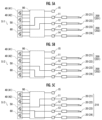
- 13A and 13B are schematic diagrams showing the connection state when performing high-frequency thermal coagulation with a quad-polar output format.
- 1A to 1D are schematic diagrams showing how high-frequency current flows in a treatment subject.
- 11A to 11C are schematic diagrams showing connection states for measuring impedance when the output format is quad-polar.
- 1A and 1B are schematic diagrams showing an example in which electrodes included in the same first electrode group in the first connection state are made not to have the same polarity in the second connection state.
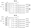
- 1A and 1B are schematic diagrams showing an example in which more than four electrodes can be used.
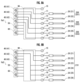
- 13A and 13B are schematic diagrams showing an example in which three or more high-frequency output units are provided.
- FIG. 1 is a schematic diagram showing the appearance of a high-frequency treatment device 1 according to an embodiment of the present invention.
- the high-frequency treatment device 1 of this embodiment is for applying a high-frequency voltage to a living body such as a human or animal to be treated, passing a high-frequency current through the living body, and performing treatment using either high-frequency thermocoagulation or pulsed high-frequency.
- the high-frequency treatment device 1 comprises a main body 10, four electrodes 20 (21, 22, 23, and 24) connected to the main body 10, and a return electrode plate 30 connected to the main body 10.
- the main body 10 houses or supports the internal configuration described below.
- the operation unit 16 is composed of a touch panel display 16a that accepts input operations such as various settings and displays various information, a start button 16b that accepts an operation to start treatment, a stop button 16c that accepts an operation to end treatment, a control knob 16d for starting output and adjusting the output voltage during manual operation, an output indicator 16e that is lit while high-frequency power is being output, and an alarm indicator 16f that is lit when an alarm is issued.
- a handle 17 is provided on the top of the main body 10 for carrying the main body 10. Also, although not shown, the back of the main body 10 is provided with a power connector that is connected to a commercial AC power source to receive power, a power switch that accepts the power-on operation, and a USB connector for connecting an external storage means. Also, a speaker (alarm) that outputs a buzzer sound is provided inside the main body 10 along with a drive circuit.
- the electrode 20 is inserted into the inside of a target for high-frequency treatment in order to pass a high-frequency current through the target.
- the electrode 20 is configured in a needle-like shape that can be directly inserted into the human body, etc.
- the electrode 20 also has a built-in thermocouple 20c for measuring the temperature around the electrode 20 during treatment.
- the electrodes 20 are electrically connected to the main body 10 via the electrode cable 26 and the electrode connectors 11 to 14. In this embodiment, up to four electrodes 20 (21 to 24) can be used simultaneously.
- the electrodes 20 may be of other shapes, such as a rod-like shape that is inserted into a needle tube or catheter, or a pad-like shape that is placed on the surface of the living body.
- the thermocouple 20c may be provided separately from the electrodes 20.
- the counter electrode 30 is a flat electrode that is attached to the surface of the treatment target, and is used to pass a high-frequency current between it and the electrode 20. In this embodiment, it is possible to pass a high-frequency current between the electrode 20 and the counter electrode 30, or between the electrodes 20 (for example, between the electrodes 21 and 22) to perform treatment.
- the counter electrode 30 is electrically connected to the main body 10 via the counter electrode cable 31 and the counter electrode connector 15. Note that, although the counter electrode 30 is configured as a rectangular flat plate in this embodiment, the counter electrode 30 may have other shapes.
- FIG. 2 is a block diagram showing an outline of the internal configuration of the high-frequency treatment device 1.
- the high-frequency treatment device 1 includes, as its internal configuration, a high-frequency output section 40 (first high-frequency output section 41 and second high-frequency output section 42), an impedance measuring section 50, a stimulation signal output section 60, a temperature measuring section 70, a voltage measuring section 80, and a control section 100 (main control section 101 and sub-control section 102).
- the high frequency output unit 40 generates and outputs high frequency power of a preset frequency (e.g., 470-490 kHz) and a voltage (e.g., 18-80 Vrms) based on the power supplied from a commercial AC power source and a control signal from the main control unit 101.
- a preset frequency e.g., 470-490 kHz
- a voltage e.g., 18-80 Vrms
- the high-frequency output unit 40 is connected to the electrode connectors 11-14 and the return electrode connector 15 via the switching unit 90.
- the electrode 20 is connected to the high-frequency output unit 40 via the electrode connectors 11-14 and the switching unit 90
- the return electrode 30 is connected to the high-frequency output unit 40 via the return electrode connector 15 and the switching unit 90.
- Each of the high-frequency output units 40 is composed of a known circuit having a transformer, which insulates the treatment target from the commercial AC power supply.
- the impedance measuring unit 50 is composed of known circuits, etc., and generates and outputs an impedance measurement signal consisting of relatively weak AC power to measure the impedance between the electrode 20 and the return electrode 30 or between the electrodes 20, i.e., the impedance of the site through which high-frequency current flows in the treatment subject.
- the impedance measuring unit 50 is connected to the electrode connectors 11-14 and the return electrode connector 15 via the switching unit 90.
- the electrode 20 is connected to the impedance measuring unit 50 via the electrode connectors 11-14 and the switching unit 90
- the return electrode 30 is connected to the impedance measuring unit 50 via the return electrode connector 15 and the switching unit 90.
- the impedance measuring unit 50 outputs an impedance measurement signal under the control of the sub-control unit 102, and samples and discretizes the impedance measurement signal that has flowed through the treatment target at a predetermined sampling period, and performs a discrete Fourier transform to calculate the real and imaginary parts of the complex impedance. These calculated values are sent to the sub-control unit 102.
- the impedance measurement signal is a sine wave with a frequency of 50 kHz, and the maximum output current is set to approximately 4 mA and the maximum output voltage to approximately 500 mVrms. Details will be described later, but in this embodiment, the intermittent output of the impedance measurement signal continues before and after the start of treatment, making it possible to perform high-frequency treatment efficiently.
- the stimulation signal output unit 60 is composed of known circuits, etc., and generates and outputs a stimulation signal for nerve exploration. Normally, nerve exploration is performed before high-frequency treatment is performed to detect the presence or absence of nerves (sensory nerves and motor nerves) around the electrode 20.
- the stimulation signal output unit 60 is connected to the electrode connectors 11-14 and the return electrode connector 15 via the switching unit 90. Therefore, the electrode 20 is connected to the stimulation signal output unit 60 via the electrode connectors 11-14 and the switching unit 90, and the return electrode 30 is connected to the stimulation signal output unit 60 via the return electrode connector 15 and the switching unit 90.
- the stimulation signal output unit 60 operates under the control of the sub-control unit 102, and sends a stimulation signal through the treatment target via the electrode 20.
- the user confirms the presence of sensory nerves around the electrode 20 when the treatment target senses the stimulation signal, and confirms the presence of motor nerves around the electrode 20 when the treatment target's muscle contracts in response to the stimulation signal.
- the stimulation signal is a bipolar square wave with a predetermined pulse width, and is output intermittently at a predetermined frequency.
- the temperature measurement unit 70 is composed of known circuits, etc., and measures the temperature around the electrode 20 using a thermocouple 20c.
- the temperature measurement unit 70 is connected to the thermocouple 20c in the electrode 20 via the electrode connectors 11 to 14, but a separate connector for the thermocouple 20c may also be provided.
- the temperature measurement unit 70 operates under the control of the sub-control unit 102, generating a temperature measurement signal (e.g., 25 mV/°C) based on the signal received from the thermocouple 20c and sending it to the sub-control unit 102.
- the temperature measurement unit 70 also outputs an output stop signal to the high frequency output unit 40 and the main control unit 101 if a temperature abnormality occurs (if the measured temperature value is 7°C or more higher than the set temperature).
- the high frequency output unit 40 that receives the output stop signal stops outputting high frequency power.
- the main control unit 101 that receives the output stop signal turns on the alarm indicator 16f and outputs an alarm buzzer sound from the speaker.
- the voltage measurement unit 80 is composed of known circuits, etc., and measures the voltage of the high frequency power output by the high frequency output unit 40.
- the voltage measurement unit 80 individually measures the voltage of the high frequency power output by the first high frequency output unit 41 and the second high frequency output unit 42, and generates a voltage measurement signal based on this and transmits it to the main control unit 101.
- the switching unit 90 is composed of multiple reed relays or semiconductor switches, and switches the connection state between the first high-frequency output unit 41, the second high-frequency output unit 42, the impedance measuring unit 50, and the stimulation signal output unit 60 and the electrode connectors 11 to 14 and the return electrode connector 15.
- the switching unit 90 operates under the control of the sub-control unit 102, and switches which of the first high-frequency output unit 41, the second high-frequency output unit 42, the impedance measurement unit 50, and the stimulation signal output unit 60 is connected to the electrode connectors 11-14 and the return electrode connector 15. In other words, the switching unit 90 switches whether to output high-frequency power, an impedance measurement signal, or a stimulation signal to the electrodes 21-24 and return electrode 30 connected to the electrode connectors 11-14 and the return electrode connector 15.
- the switching unit 90 also operates under the control of the sub-control unit 102, and switches which combination (i.e., electrode set) of the electrodes 21-24 and return electrode 30 connected to the electrode connectors 11-14 and the return electrode connector 15 is to receive the high-frequency current, the impedance measurement signal, or the stimulation signal.
- the control unit 100 controls each part of the high-frequency treatment device 1 to perform high-frequency treatment.
- the control unit 100 is made up of a main control unit 101 that controls the high-frequency output unit 40 and the operation unit 16, and a sub-control unit 102 that controls the impedance measurement unit 50, the stimulation signal output unit 60, the temperature measurement unit 70, and the switching unit 90.
- the sub-control unit 102 which controls the parts located closer to the treatment target than the high-frequency output unit 40, separately from the main control unit 101, it is possible to more reliably insulate the treatment target from the commercial AC power source.
- the main control unit 101 has a known configuration including a CPU, ROM, RAM, and auxiliary storage device.
- the main control unit 101 starts and ends high-frequency treatment based on input operations received by the operation unit 16 and information stored in the ROM, etc.
- the main control unit 101 also controls the output of the high-frequency output unit 40 during treatment. Specifically, the main control unit 101 controls the output so that the measured temperature value received from the sub-control unit 102 is approximately equal to the set temperature, using the output voltage as the manipulated variable in high-frequency thermal coagulation method and the output pulse width as the manipulated variable in pulsed high-frequency method (the output voltage is fixed to the voltage setting value).
- the main control unit 101 also controls the on/off of the high-frequency power output at a set cycle in both high-frequency thermal coagulation method and pulsed high-frequency method.
- the main control unit 101 also displays information such as elapsed time, temperature measurement values, impedance measurement values, voltage measurement values, and current measurement values on the touch panel display 16a.
- the current measurement values are calculated by the main control unit 101 from the voltage measurement values and impedance measurement values.
- the sub-controller 102 has a known configuration including a CPU, ROM and RAM.
- the sub-controller 102 calculates a temperature measurement value based on the temperature measurement signal received from the temperature measuring unit 70 and transmits it to the main control unit 101.
- the sub-controller 102 also calculates an impedance measurement value based on the real and imaginary parts of the complex impedance received from the impedance measuring unit 50 and a calibration value generated in advance and transmits it to the main control unit 101.
- These calibration values are generated by the sub-controller 102 each time the high-frequency treatment device 1 is started.
- the sub-controller 102 causes the impedance measuring unit 50 to measure the impedance of the built-in 100 ⁇ fixed resistor and 1 k ⁇ fixed resistor. Then, based on the measurement result of the 100 ⁇ fixed resistor, a low resistance calibration value is generated, based on the measurement result of the 1 k ⁇ fixed resistor, and these are stored in RAM.
- the impedance measurement value is calculated using the high resistance calibration value in the first calculation, and in subsequent calculations, a predetermined value (300 ⁇ or 400 ⁇ ) is used as a threshold value, and either the low resistance calibration value or the high resistance calibration value is used based on the previous calculation result.
- the sub-controller 102 also controls the on/off of multiple switches provided in the switching unit 90, and switches the connection states between the first high-frequency output unit 41, the second high-frequency output unit 42, the impedance measuring unit 50 and the stimulation signal output unit 60 and the electrode connectors 11-14 and the return electrode connector 15. Specifically, the sub-controller 102 causes the switching unit 90 to switch the connection states based on the connection states of the electrodes 20 and return electrode 30 detected from the electrode connectors 11-14 and the return electrode connector 15, as well as the mode information and output format information received from the main controller 101.
- a menu mode in which various settings are made
- a stimulation mode in which a stimulation signal is output to perform nerve exploration
- a region mode in which high-frequency power is output to perform high-frequency thermocoagulation
- a PRF mode in which high-frequency power is output to perform pulsed high-frequency therapy.
- monopolar which uses at least one of electrodes 21-24 and return electrode 30 as an electrode set
- bipolar which uses electrodes 21 and 22 or electrodes 23 and 24 as an electrode set
- tripolar which uses electrodes 21-23 as an electrode set
- quadpolar which uses electrodes 21-24 as an electrode set.
- Figures 3A and 3B are schematic diagrams showing the connection state when performing high-frequency thermal coagulation with quad-polar output format. Before starting high-frequency thermal coagulation, various checks are performed, the electrodes 20 are placed on the treatment target, and nerve exploration is performed using the placed electrodes 20. The main control unit 101 starts treatment based on the time and temperature set in region mode and the start button 16b or control knob 16d accepting a start operation.
- the sub-controller 102 controls the switching unit 90 to switch the connection state between the high-frequency output unit 40 and the electrode 20 at a specific period (100 msec in this embodiment). Specifically, the sub-controller 102 controls the switching unit 90 to switch the connection state between the first connection state Sq1 shown in FIG. 3A and the second connection state Sq2 shown in FIG. 3B.
- the first connection state Sq1 is a connection state in which a different first electrode set 200 is connected to each of the two high frequency output units 40.
- the first electrode set 201 consisting of electrodes 21 and 22 is connected to the first high frequency output unit 41
- the first electrode set 202 consisting of electrodes 23 and 24 is connected to the second high frequency output unit 42.
- the second connection state Sq2 is a connection state in which a second electrode set 210, which is a combination of multiple first electrode sets 200, is connected to one high frequency output section 40.
- the second electrode set 210 consisting of electrodes 21 to 24 (i.e., an electrode set which is a combination of first electrode sets 201 and 202) is connected to the first high frequency output section 41.
- electrodes 21 and 22 have the same polarity (connected to the same output terminal), and electrodes 23 and 24 have the same polarity.
- FIGS. 4A to 4D are schematic diagrams showing how the high-frequency current flows in the treatment target, showing the electrode 20 placed on the treatment target as viewed in the axial direction.
- Figures 4A and 4B show the case where electrodes 21 to 24 are arranged in a row.
- the first connection state Sq1 as shown in Figure 4A, high-frequency current flows between electrodes 21 and 22, and high-frequency current flows between electrodes 23 and 24.
- the treatment target is heated in area 301 between electrodes 21 and 22 and their surroundings, and area 302 between electrodes 23 and 24 and their surroundings.
- an unheated area may occur between area 301 and area 302, as shown in Figure 4A.
- Figures 4C and D show the case where electrodes 21 to 24 are arranged in two rows.
- the treatment target in area 301 between electrodes 21 and 22 and in the surrounding area, and in area 302 between electrodes 23 and 24 and in the surrounding area.
- the heating states in the two connection states complement each other, making it possible to efficiently heat a wide area between and around the four electrodes 21-24 in a single treatment.
- the electrodes 21 and 22 included in the first electrode set 201 have the same polarity, and the electrodes 23 and 24 included in the first electrode set 202 have the same polarity, thereby reducing the degree to which the regions 301 and 302 are double heated, making uneven heating less likely to occur. Furthermore, by reducing the degree of double heating in this manner, the frequency of intervention of output control (reduction of output voltage) to lower the temperature is also reduced, allowing for more efficient heating.
- all of the electrodes 21 to 24 are included in one second electrode set 210, making it possible to comprehensively heat a wide area between and around all of the electrodes 21 to 24.
- a 9 msec stop period during which the output of high frequency power from the first high frequency output unit 41 and the second high frequency output unit 42 is stopped is provided at a cycle of 100 msec, and the switching operation of the switching unit 90 is performed during this stop period.
- the impedance measurement unit 50 measures the impedance during this stop period, making it possible to perform treatment more efficiently.
- Figures 5A to 5C are schematic diagrams showing the connection state for measuring impedance when the output format is quad-polar.
- the sub-controller 102 controls the switching unit 90 so that the third connection state Si1, Si2 or Si3 that connects the impedance measuring unit 50 and the electrode 20 continues for 5 msec during the pause period between the first connection state Sq1 and the second connection state Sq2.
- the sub-controller 102 then controls the impedance measuring unit 50 so that it outputs an impedance measurement signal during this 5 msec period to measure the impedance.
- Si1 to Si3 there are three types of third connection states Si1 to Si3. That is, in this embodiment, there are three types of third connection states: Si1 (FIG. 5A) in which electrodes 21 and 22 are connected to the impedance measurement unit 50 to measure the impedance of the first electrode group 201; Si2 (FIG. 5B) in which electrodes 23 and 24 are connected to the impedance measurement unit 50 to measure the impedance of the first electrode group 202; and Si3 (FIG. 5C) in which electrodes 21 to 24 are connected to the impedance measurement unit 50 to measure the impedance of the second electrode group 210.
- the switching unit 90 first switches from the first connection state Sq1 to the third connection state Si1 or Si2, and after 5 msec, switches from the third connection state Si1 or Si2 to the second connection state Sq2.
- the state to be switched to first is changed for each switch.
- the switching unit 90 first switches from the second connection state Sq2 to the third connection state Si3 during the stop period, and after 5 msec, switches from the third connection state Si3 to the first connection state Sq1.
- the impedance measurement unit 50 measures the impedance during the downtime required to switch between the first connection state Sq1 and the second connection state Sq2, making it possible to measure the impedance with higher accuracy than the conventional method of calculating the impedance from the measured voltage and current values of the high-frequency power. Furthermore, defects such as misalignment or detachment of the electrode 20 can be detected from changes in the measured impedance value during treatment, and by improving the accuracy of the impedance measurement, it becomes easier to detect such defects early and it becomes possible to efficiently perform heating using high-frequency current.
- FIGS. 6A and 6B are schematic diagrams showing an example in which electrodes 20 included in the same first electrode group 200 in the first connection state Sq1 do not have the same polarity in the second connection state Sq2.
- electrodes 21 and 23 have the same polarity
- electrodes 22 and 23 have the same polarity.
- the third connection state Si3 in this example is a connection state in which the first high frequency output unit 41 in the second connection state Sq2 is replaced with an impedance measurement unit 50.
- the polarity of the electrodes 21-24 in the second connection state Sq2 is not particularly limited, and can be appropriately selected depending on the type and state of the area to be heated, and the arrangement of the electrodes 21-24. Furthermore, the polarity of the electrodes 21-24 in the second connection state Sq2 may be changeable before treatment, or may be changeable during treatment.
- FIGS. 7A and 7B are schematic diagrams showing an example in which five or more electrodes 20 can be used. Specifically, in this example, an electrode connector 18 and an electrode 25 are added, and a first electrode set 201 is made up of electrodes 23 to 25, and a second electrode set 210 is made up of electrodes 21 to 25.
- the number of electrodes 20 that can be used by the high-frequency treatment device 1 and the number of electrodes 20 included in the first electrode set 200 in the first connection state Sq1 are not particularly limited, and any number can be used. Furthermore, it goes without saying that it is not necessary to use all of the electrodes 20 in the treatment, and only a portion of the usable electrodes 20 may be used.
- FIGS. 8A and 8B are schematic diagrams showing an example of a case where three or more high-frequency output units 40 are provided. Specifically, in this example, a third high-frequency output unit 43, electrode connectors 18 and 19, and electrodes 25 and 26 are added. In addition, a first electrode set 203 consisting of electrodes 25 and 26 connected to the third high-frequency output unit 43 is added to the first connection state Sq1, and a second electrode set 210 is composed of electrodes 21 to 26.
- the number of high-frequency output units 40 provided in the high-frequency treatment device 1 is not particularly limited, and any number can be adopted together with the electrodes 20, and the number of first electrode sets 200 can be increased according to the number of high-frequency output units 40.
- the second electrode set 210 does not need to be a combination of all of the first electrode sets 200, and for example, in the example shown in Figures 8A and B, the second electrode set 210 may be composed of electrodes 21 to 24. Furthermore, it goes without saying that it is not necessary to use all of the high-frequency output units 40 in treatment.
- the high-frequency treatment device and high-frequency treatment method of the present invention are not limited to the above-mentioned embodiments, and various modifications can be made within the scope of the gist of the present invention.
- the high-frequency treatment device and high-frequency treatment method of the present invention are not limited to those performing high-frequency thermocoagulation and pulsed high-frequency treatment, and may be used for other purposes, such as cauterization of tumors.
- the treatment target is not limited to the human body or animals, and may be other objects.
Landscapes
- Health & Medical Sciences (AREA)
- Surgery (AREA)
- Engineering & Computer Science (AREA)
- Life Sciences & Earth Sciences (AREA)
- Medical Informatics (AREA)
- Molecular Biology (AREA)
- Nuclear Medicine, Radiotherapy & Molecular Imaging (AREA)
- Plasma & Fusion (AREA)
- Biomedical Technology (AREA)
- Heart & Thoracic Surgery (AREA)
- Physics & Mathematics (AREA)
- Otolaryngology (AREA)
- Animal Behavior & Ethology (AREA)
- General Health & Medical Sciences (AREA)
- Public Health (AREA)
- Veterinary Medicine (AREA)
- General Induction Heating (AREA)
- Drying Of Semiconductors (AREA)
- Radiation-Therapy Devices (AREA)
- Electrotherapy Devices (AREA)
Abstract
Description
本発明は、処置対象に高周波電流を流して各種処置を行う高周波処置装置および高周波処置方法に関する。 The present invention relates to a high-frequency treatment device and a high-frequency treatment method that perform various treatments by passing a high-frequency current through a treatment target.
従来、医療の分野では、人間や動物等の体内に電極を配置し、この電極から高周波電流を流して組織の焼灼(アブレーション)等を行う高周波処置が広く用いられている。また、近年では、疼痛治療の一つとして高周波処置により神経ブロックを行う手法が注目されている。この高周波処置による神経ブロックは、従来の薬剤を用いる手法と比較して周囲の組織への副作用が少なく、また効果が長期間持続するという利点を有している。 Conventionally, in the medical field, high-frequency treatment has been widely used, in which electrodes are placed inside the body of a human or animal, and high-frequency current is passed through the electrodes to cauterize (ablate) tissue. In recent years, a technique for performing nerve blocks using high-frequency treatment has been attracting attention as a form of pain treatment. Nerve blocks using high-frequency treatment have the advantage of causing fewer side effects on surrounding tissues and lasting effects for a long period of time compared to conventional methods that use drugs.
高周波処置による神経ブロックには、高周波熱凝固法とパルス高周波法の二種類がある。このうち高周波熱凝固法は、電極から流れる高周波電流により神経組織の一部を80℃程度の温度で数分間加熱して熱凝固させ、これにより痛みの信号を遮断するものであり、パルス高周波法は、神経組織の一部に高周波電流を完結的に流すことにより42℃以下の温度で十数分間加熱し、神経を損傷させることなく痛みの信号を遮断するものである。 There are two types of nerve blocks using radiofrequency treatment: radiofrequency thermocoagulation and pulsed radiofrequency. Radiofrequency thermocoagulation uses a radiofrequency current flowing from an electrode to heat part of the nerve tissue to a temperature of around 80°C for several minutes, causing it to thermally coagulate, thereby blocking pain signals. Pulsed radiofrequency uses a continuous flow of radiofrequency current through part of the nerve tissue, heating it to a temperature of 42°C or less for about 10 minutes, blocking pain signals without damaging the nerves.
このような神経ブロックでは、1本の神経の一部をピンポイントに狙って加熱するだけでなく、複数本の神経をまとめて加熱する場合がある。例えば、仙腸関節疼痛に対する神経ブロックを高周波処置にて行う場合、仙骨神経後枝の外側枝の広い領域にわたって加熱する必要がある(例えば、特許文献1参照)。 In such nerve blocks, not only is heating done by pinpointing a part of a single nerve, but multiple nerves may be heated at once. For example, when performing a nerve block for sacroiliac joint pain using high-frequency treatment, it is necessary to heat a wide area of the lateral branch of the posterior branch of the sacral nerve (see, for example, Patent Document 1).
このため従来の手法では、特許文献1の図1および2に示されるように、複数の針(ニードル)を外側枝の近傍に穿刺してこの針内に電極を挿入し、特許文献1の図5に示されるように、これらの電極と患者の皮膚表面に配置した対極板との間で高周波電流を流す(所謂モノポーラ)、または隣接する2つの電極間で高周波電流を流す(所謂バイポーラ)ことによって処置が行われていた。
For this reason, in the conventional method, as shown in Figures 1 and 2 of
しかしながら、従来のモノポーラでは1回の処置に1つの電極しか使用せず、1つの電極で加熱可能な領域も狭いことから、広い領域を加熱しようとする場合には電極を差し替えて複数回の処置を行う必要があり、手間と時間を要するという問題があった。また、バイポーラでは2つの電極間およびその周辺の領域を加熱することから、1回の処置でモノポーラよりも広い領域を加熱可能ではあるものの、仙腸関節疼痛に対する神経ブロックを行う場合には、やはり電極を差し替えて複数回の処置を行う必要があった。 However, conventional monopolar devices only use one electrode per treatment, and the area that can be heated with one electrode is small, so when trying to heat a wide area, it is necessary to replace the electrode and perform the treatment multiple times, which is time-consuming and laborious. Also, bipolar devices heat the area between the two electrodes and the surrounding area, so although it is possible to heat a wider area than monopolar devices with one treatment, it is still necessary to replace the electrode and perform multiple treatments when performing a nerve block for sacroiliac joint pain.
本発明は、このような実情に鑑み、効率的に広い領域を加熱することが可能な高周波処置装置および高周波処置方法を提供しようとするものである。 In view of these circumstances, the present invention aims to provide a high-frequency treatment device and a high-frequency treatment method that can efficiently heat a wide area.
本発明の高周波処置装置は、高周波電力を出力する複数の高周波出力部と、前記高周波出力部に接続され、処置対象に配置される複数の電極と、前記高周波出力部と前記電極の間に設けられ、少なくとも2つの前記電極を組み合わせた電極組のうちのいずれの前記電極組に高周波電流が流れるかを切り替える切替部と、処置中に前記高周波出力部毎に異なる前記電極組を接続させる第1の接続状態と1つの前記高周波出力部に前記第1の接続状態における複数の前記電極組を合成した前記電極組を接続させる第2の接続状態とを特定の周期で切り替えるように前記切替部を制御する制御部と、を有することを特徴とする。 The high-frequency treatment device of the present invention is characterized by having a plurality of high-frequency output units that output high-frequency power, a plurality of electrodes that are connected to the high-frequency output units and placed on a treatment target, a switching unit that is provided between the high-frequency output units and the electrodes and that switches which of the electrode sets each consisting of at least two of the electrodes to which a high-frequency current flows, and a control unit that controls the switching unit to switch, at a specific period, between a first connection state in which a different electrode set is connected to each of the high-frequency output units during treatment and a second connection state in which an electrode set formed by combining the plurality of electrode sets in the first connection state is connected to one of the high-frequency output units.
また、本発明の高周波処置方法は、処置対象に複数の電極を配置し、少なくとも2つの前記電極を組み合わせた電極組のうちいずれかの前記電極組に複数の高周波出力部からの高周波電流を流して処置を行う高周波処置方法において、処置中に前記高周波出力部毎に異なる前記電極組を接続させる第1の接続状態と1つの前記高周波出力部に前記第1の接続状態における複数の前記電極組を合成した前記電極組を接続させる第2の接続状態とを特定の周期で切り替えることを特徴とする。 The high-frequency treatment method of the present invention is a high-frequency treatment method in which a plurality of electrodes are placed on a treatment target, and a high-frequency current is passed from a plurality of high-frequency output units to any one of the electrode sets, each of which is a combination of at least two of the electrodes, to perform treatment, and is characterized in that during treatment, a first connection state in which a different electrode set is connected to each of the high-frequency output units and a second connection state in which an electrode set formed by combining the plurality of electrode sets in the first connection state is connected to one of the high-frequency output units are switched at a specific period.
本発明の高周波処置装置および高周波処置方法によれば、第1の接続状態における加熱状態と第2の接続状態における加熱状態が、互いに加熱度合いの低い部分を補い合うようにすることが可能となるため、効率的に広い領域を加熱することができる。 The high-frequency treatment device and method of the present invention allow the heating state in the first connection state and the heating state in the second connection state to complement each other's less heated areas, making it possible to efficiently heat a wide area.
また、本発明の高周波処置装置において、前記第2の接続状態は、前記第1の接続状態において同一の前記電極組に含まれていた前記電極が同一の極性となる接続状態であることが好ましい。 In addition, in the high-frequency treatment device of the present invention, it is preferable that the second connection state is a connection state in which the electrodes included in the same electrode group in the first connection state have the same polarity.
これによれば、第1の接続状態および第2の接続状態において二重に加熱される度合いを低減し、加熱むらを低減することが可能となるため、効率的に広い領域を加熱することができる。 This reduces the degree of double heating in the first and second connection states, making it possible to reduce uneven heating, and therefore to efficiently heat a wide area.
また、本発明の高周波処置装置において、前記第2の接続状態は、1つの前記高周波出力部に全ての前記電極を含む前記電極組を接続させる接続状態であることが好ましい。 Furthermore, in the high-frequency treatment device of the present invention, it is preferable that the second connection state is a connection state in which the electrode set including all of the electrodes is connected to one of the high-frequency output sections.
これによれば、複数の電極の間およびその周辺を網羅的に加熱することが可能となるため、効率的に広い領域を加熱することができる。 This makes it possible to comprehensively heat the areas between and around multiple electrodes, allowing a wide area to be heated efficiently.
また、本発明の高周波処置装置において、前記切替部を介して前記電極に接続され、インピーダンス測定信号を出力することでインピーダンスを測定するインピーダンス測定部を有し、前記制御部は、前記第1の接続状態と前記第2の接続状態の間に前記インピーダンス測定部に前記電極組を接続させる第3の接続状態を設けるように前記切替部を制御することが好ましい。 In addition, the high-frequency treatment device of the present invention preferably has an impedance measuring unit that is connected to the electrodes via the switching unit and measures impedance by outputting an impedance measurement signal, and the control unit controls the switching unit to provide a third connection state between the first connection state and the second connection state in which the electrode set is connected to the impedance measuring unit.
これによれば、第1の接続状態と第2の接続状態の切り替えが高周波電力の出力を停止する停止期間中に行う必要があるところ、この停止期間を活用して専用のインピーダンス測定部による高精度なインピーダンス測定を行うことが可能となるため、効率的に広い領域を加熱することができる。 As a result, although switching between the first and second connection states must be performed during the stop period when the output of high-frequency power is stopped, this stop period can be utilized to perform highly accurate impedance measurements using a dedicated impedance measuring unit, making it possible to efficiently heat a wide area.
本発明の高周波処置装置および高周波処置方法によれば、効率的に広い領域を加熱することが可能という優れた効果を奏し得る。 The high-frequency treatment device and method of the present invention have the excellent effect of being able to efficiently heat a wide area.
以下、本発明の実施の形態を、添付図面を参照して説明する。 The following describes an embodiment of the present invention with reference to the attached drawings.
図1は、本発明の実施形態に係る高周波処置装置1の外観を示した概略図である。本実施形態の高周波処置装置1は、処置対象である人間や動物等の生体に対して高周波電圧を印加して生体内に高周波電流を流し、高周波熱凝固法およびパルス高周波法のいずれかによる処置を行うためのものである。図1に示されるように、高周波処置装置1は、本体10と、本体10に接続された4つの電極20(21、22、23および24)と、本体10に接続された対極板30と、を備えている。
FIG. 1 is a schematic diagram showing the appearance of a high-
本体10は、後述する内部構成を収容または支持するものである。本体10の正面には、電極20が接続される4つの電極コネクタ11~14、および対極板30が接続される対極板コネクタ15が下部に設けられている。本体10の正面にはまた、使用者の操作を受け付ける操作部16が設けられている。操作部16は、各種設定等の入力操作を受け付けると共に各種情報の表示を行うタッチパネルディスプレイ16aと、処置の開始操作を受け付けるスタートボタン16bと、処置の終了操作を受け付けるストップボタン16cと、マニュアル操作時に出力の開始操作および出力電圧の調整操作を行うためのコントロールノブ16dと、高周波電力の出力中に点灯される出力インジケータ16eと、警報を発する場合に点灯される警報インジケータ16fと、から構成されている。
The
本体10の上部には、本体10を持ち運ぶための取手17が設けられている。また、図示は省略するが、本体10の背面には、商用交流電源に接続されて電力の供給を受ける電源コネクタと、電源の投入操作を受け付ける電源スイッチと、外部の記憶手段を接続するためのUSBコネクタが設けられている。また、本体10の内部には、ブザー音を出力するスピーカ(警報器)が駆動回路と共に設けられている。
A
電極20は、高周波処置の処置対象の内部に挿入されて、処置対象内に高周波電流を流すためのものである。本実施形態では、電極20は、直接人体等に穿刺可能な針管状に構成されている。電極20は、先端部の非絶縁部20aを除く大部分が絶縁コーティングされた絶縁部20bとなっており、高周波電流は非絶縁部20aから出力されるようになっている。また、電極20には、処置中に電極20周辺の温度を測定するための熱電対20cが内蔵されている。
The
電極20は、電極ケーブル26および電極コネクタ11~14を介して本体10と電気的に接続されている。本実施形態では、最大4つの電極20(21~24)を同時に使用することが可能となっている。なお、電極20はその他の形状のものであってもよく、例えば針管やカテーテル内に挿入される棒状のものであってもよいし、生体の表面に配置されるパッド状のものであってもよい。また、熱電対20cは、電極20とは別体に設けられるものであってもよい。
The
対極板30は、処置対象の表面に貼り付けて配置される平板状の電極であり、電極20との間で高周波電流を流すためのものである。本実施形態では、電極20と対極板30の間、または電極20の間(例えば電極21と電極22の間)に高周波電流を流して処置を行うことが可能となっている。対極板30は、対極板ケーブル31および対極板コネクタ15を介して本体10と電気的に接続されている。なお、本実施形態では、対極板30を矩形平板状に構成しているが、対極板30の形状はその他の形状であってもよい。
The
図2は、高周波処置装置1の内部構成の概略を示したブロック図である。図2に示されるように、高周波処置装置1は、内部構成として、高周波出力部40(第1高周波出力部41および第2高周波出力部42)と、インピーダンス測定部50と、刺激信号出力部60と、温度測定部70と、電圧測定部80と、制御部100(主制御部101および副制御部102)と、を備えている。
FIG. 2 is a block diagram showing an outline of the internal configuration of the high-
高周波出力部40は、商用交流電源から供給された電力に基づき、予め設定された周波数(例えば、470~490kHz)および主制御部101からの制御信号に基づく電圧(例えば、18~80Vrms)の高周波電力を生成して出力するものである。本実施形態では、2つの高周波出力部40、すなわち第1高周波出力部41および第2高周波出力部42を設けることで、同時に2つの電極組(例えば、電極21および電極22からなる電極組と電極23および電極24からなる電極組)において出力制御を安定的に行いながら高周波電流を流すことを可能としている。
The high
高周波出力部40は、切替部90を介して、電極コネクタ11~14および対極板コネクタ15と接続されている。従って、電極20は電極コネクタ11~14および切替部90を介して高周波出力部40と接続され、対極板30は対極板コネクタ15および切替部90を介して高周波出力部40と接続される。なお、高周波出力部40は、それぞれトランスを有する既知の回路から構成されており、これにより処置対象は商用交流電源から絶縁されるようになっている。
The high-
インピーダンス測定部50は、既知の回路等から構成され、比較的微弱な交流電力からなるインピーダンス測定信号を生成して出力し、電極20と対極板30の間または電極20間のインピーダンス、すなわち処置対象において高周波電流が流れる部位のインピーダンスを測定するものである。インピーダンス測定部50は、切替部90を介して、電極コネクタ11~14および対極板コネクタ15と接続されている。従って、電極20は電極コネクタ11~14および切替部90を介してインピーダンス測定部50と接続され、対極板30は対極板コネクタ15および切替部90を介してインピーダンス測定部50と接続される。
The
インピーダンス測定部50は、副制御部102に制御されてインピーダンス測定信号を出力すると共に、処置対象を流れたインピーダンス測定信号を、所定のサンプリング周期でサンプリングして離散化し、離散フーリエ変換を行うことで、複素インピーダンスの実部および虚部の値を算出する。算出されたこれらの値は、副制御部102へ送信される。本実施形態では、インピーダンス測定信号は周波数50kHzの正弦波であり、最大出力電流が約4mA、最大出力電圧が約500mVrmsに設定されている。詳細は後述するが、本実施形態では、インピーダンス測定信号の断続的な出力を処置の開始の前後に亘って継続させることで、高周波処置を効率的に行うことを可能としている。
The
刺激信号出力部60は、既知の回路等から構成され、神経探査を行うための刺激信号を生成して出力するものである。通常、高周波処置の実施前には神経探査が行われ、電極20周辺における神経(感覚神経および運動神経)の有無が探査される。刺激信号出力部60は、切替部90を介して、電極コネクタ11~14および対極板コネクタ15と接続されている。従って、電極20は電極コネクタ11~14および切替部90を介して刺激信号出力部60と接続され、対極板30は対極板コネクタ15および切替部90を介して刺激信号出力部60と接続される。
The stimulation
刺激信号出力部60は、副制御部102に制御されて動作し、電極20を介して処置対象内に刺激信号を流す。使用者は、処置対象が刺激信号を知覚した場合に電極20周辺における感覚神経の存在を確認し、処置対象の筋肉が刺激信号に反応して収縮した場合に電極20周辺における運動神経の存在を確認する。本実施形態では、刺激信号は所定のパルス幅の双極性矩形波であり、所定の周波数で断続的に出力される。
The stimulation
温度測定部70は、既知の回路等から構成され、熱電対20cによる電極20周辺の温度測定を行うものである。本実施形態では、温度測定部70は電極コネクタ11~14を介して電極20内の熱電対20cと接続されるが、熱電対20c用のコネクタを別途設けるようにしてもよい。
The
温度測定部70は、副制御部102に制御されて動作し、熱電対20cから受信した信号に基づいて温度測定信号(例えば、25mV/℃)を生成すると共に、副制御部102に送信する。温度測定部70はまた、温度異常が発生した場合(温度測定値が設定温度よりも7℃以上高い場合)に、出力停止信号を高周波出力部40および主制御部101に出力する。出力停止信号を受信した高周波出力部40は、高周波電力の出力を停止する。また、出力停止信号を受信した主制御部101は、警報インジケータ16fを点灯させると共にスピーカから警報ブザー音を出力させる。
The
電圧測定部80は、既知の回路等から構成され、高周波出力部40が出力する高周波電力の電圧を測定するものである。電圧測定部80は、第1高周波出力部41および第2高周波出力部42が出力する高周波電力の電圧を個別に測定し、これに基づいて電圧測定信号を生成して主制御部101に送信する。
The
切替部90は、複数のリードリレーまたは半導体スイッチ等から構成され、第1高周波出力部41、第2高周波出力部42、インピーダンス測定部50および刺激信号出力部60と、電極コネクタ11~14および対極板コネクタ15との接続状態を切り替えるものである。
The switching
具体的に切替部90は、副制御部102に制御されて動作し、第1高周波出力部41、第2高周波出力部42、インピーダンス測定部50および刺激信号出力部60のいずれを電極コネクタ11~14および対極板コネクタ15に接続するかを切り替える。すなわち、切替部90は、電極コネクタ11~14および対極板コネクタ15に接続された電極21~24および対極板30に高周波電力、インピーダンス測定信号または刺激信号のいずれを出力するかを切り替える。切替部90はまた、副制御部102に制御されて動作し、電極コネクタ11~14および対極板コネクタ15に接続された電極21~24および対極板30のいずれの組み合わせ(すなわち、電極組)に高周波電流、インピーダンス測定信号または刺激信号が流れるかを切り替える。
Specifically, the switching
制御部100は、高周波処置装置1の各部を制御して高周波処置を実行するものである。本実施形態では、高周波出力部40および操作部16を制御する主制御部101と、インピーダンス測定部50、刺激信号出力部60、温度測定部70および切替部90を制御する副制御部102と、から制御部100を構成している。このように、高周波出力部40よりも処置対象側に設けられる部分を制御する副制御部102を、主制御部101とは別個に設けることで、処置対象と商用交流電源との絶縁をより確実なものとすることができる。
The
主制御部101は、CPU、ROMおよびRAMならびに補助記憶装置等の既知の構成を備えている。主制御部101は、操作部16の受け付けた入力操作、およびROM等に記憶された情報に基づいて高周波処置を開始および終了させる。また、主制御部101は、処置中に高周波出力部40の出力制御を行う。具体的に主制御部101は、高周波熱凝固法においては出力電圧を操作量とし、パルス高周波法においては出力パルス幅を操作量として(出力電圧は、電圧設定値に固定)、副制御部102から受信した温度測定値が設定温度と略等しくなるように出力制御を行う。また、主制御部101は、高周波熱凝固法およびパルス高周波法のいずれにおいても、設定された周期で高周波電力の出力のオン/オフを制御する。
The
また、処置中に主制御部101は、経過時間、温度測定値、インピーダンス測定値、電圧測定値および電流測定値等の情報をタッチパネルディスプレイ16aに表示させる。なお、本実施形態では、電流測定値は、主制御部101によって電圧測定値およびインピーダンス測定値から算出される。
During treatment, the
副制御部102は、CPU、ROMおよびRAM等の既知の構成を備えている。副制御部102は、温度測定部70から受信した温度測定信号に基づいて温度測定値を算出し、主制御部101に送信する。副制御部102はまた、インピーダンス測定部50から受信した複素インピーダンスの実部および虚部の値と、事前に生成したキャリブレーション値とに基づいてインピーダンス測定値を算出し、主制御部101に送信する。
The sub-controller 102 has a known configuration including a CPU, ROM and RAM. The sub-controller 102 calculates a temperature measurement value based on the temperature measurement signal received from the
このキャリブレーション値は、高周波処置装置1の起動毎に副制御部102によって生成される。副制御部102は、高周波処置装置1の電源が投入されると、内蔵された100Ωの固定抵抗および1kΩの固定抵抗のインピーダンスをインピーダンス測定部50に測定させる。そして、100Ωの固定抵抗の測定結果に基づいて低抵抗用キャリブレーション値を生成し、1kΩの固定抵抗の測定結果に基づいて高抵抗用キャリブレーション値を生成し、RAMに記憶する。インピーダンス測定値の算出は、初回の算出では、高抵抗用キャリブレーション値を使用して行い、次回以降の算出では、所定の値(300Ωまたは400Ω)を閾値とし、前回の算出結果に基づいて低抵抗用キャリブレーション値および高抵抗用キャリブレーション値のいずれかを使用して行われる。
These calibration values are generated by the sub-controller 102 each time the high-
また、副制御部102は、切替部90の備える複数のスイッチのオン/オフを制御し、第1高周波出力部41、第2高周波出力部42、インピーダンス測定部50および刺激信号出力部60と、電極コネクタ11~14および対極板コネクタ15との接続状態を切り替えさせる。具体的に副制御部102は、電極コネクタ11~14および対極板コネクタ15から検出した電極20および対極板30の接続状態、ならびに主制御部101から受信したモード情報および出力形式情報に基づいて、切替部90に接続状態を切り替えさせる。
The sub-controller 102 also controls the on/off of multiple switches provided in the
なお、本実施形態における動作モードは、各種設定等が行われるメニューモード、刺激信号を出力して神経探査を行うスティミュレーションモード、高周波電力を出力して高周波熱凝固法を行うリージョンモード、および高周波電力を出力してパルス高周波法を行うPRFモードの4種類となっている。また、出力形式は、電極21~24の少なくとも1つおよび対極板30を電極組とするモノポーラ、電極21および22または電極23および24を電極組とするバイポーラ、電極21~23を電極組とするトリポーラ、ならびに電極21~24を電極組とするクアッドポーラの4種類となっている。
In this embodiment, there are four operating modes: a menu mode in which various settings are made, a stimulation mode in which a stimulation signal is output to perform nerve exploration, a region mode in which high-frequency power is output to perform high-frequency thermocoagulation, and a PRF mode in which high-frequency power is output to perform pulsed high-frequency therapy. There are also four output formats: monopolar, which uses at least one of electrodes 21-24 and return
次に、本実施形態の特徴であるクアッドポーラを出力形式として高周波熱凝固法を行う場合の動作について説明する。 Next, we will explain the operation when performing high-frequency thermal coagulation using the quad-polar output format, which is a feature of this embodiment.
図3AおよびBは、出力形式をクアッドポーラとして高周波熱凝固法を行う場合の接続状態を示した概略図である。高周波熱凝固法の開始前には、各種チェック、電極20の処置対象への配置、および配置した電極20による神経探査が行われる。主制御部101は、リージョンモードにおいて設定時間および設定温度が設定され、スタートボタン16bまたはコントロールノブ16dが開始操作を受け付けたことに基づいて、処置を開始する。
Figures 3A and 3B are schematic diagrams showing the connection state when performing high-frequency thermal coagulation with quad-polar output format. Before starting high-frequency thermal coagulation, various checks are performed, the
処置中に副制御部102は、出力形式がクアッドポーラの場合、特定の周期(本実施形態では、100msec)で、高周波出力部40と電極20の接続状態を切り替えるように、切替部90を制御する。具体的に副制御部102は、図3Aに示される第1の接続状態Sq1と図3Bに示される第2の接続状態Sq2の間で接続状態を切り替えるように切替部90を制御する。
When the output format is quad-polar during treatment, the sub-controller 102 controls the switching
このうち、第1の接続状態Sq1は、2つの高周波出力部40毎に異なる第1の電極組200を接続する接続状態である。本実施形態では、第1の接続状態Sq1において、第1高周波出力部41に電極21および22からなる第1の電極組201を接続すると共に、第2高周波出力部42に電極23および24からなる第1の電極組202を接続している。
Among these, the first connection state Sq1 is a connection state in which a different first electrode set 200 is connected to each of the two high
また、第2の接続状態Sq2は、1つの高周波出力部40に複数の第1の電極組200を合成した第2の電極組210を接続する接続状態である。本実施形態では、第2の接続状態Sq2において、第1高周波出力部41に電極21~24からなる第2の電極組210(すなわち、第1の電極組201および202を合成した電極組)を接続している。なお、第2の接続状態Sq2では、互いに短絡されることで、電極21および22が同一の極性となる(同一の出力端子に接続される)と共に、電極23および24が同一の極性となっている。
The second connection state Sq2 is a connection state in which a second electrode set 210, which is a combination of multiple first electrode sets 200, is connected to one high
本実施形態では、このように特定の周期で第1の接続状態Sq1および第2の接続状態Sq2を切り替えることで、高周波熱凝固法において効率的に広い領域を加熱することを可能としている。図4A~Dは、処置対象における高周波電流の流れ方を模式的に示した概略図であり、処置対象に配置された電極20を軸方向に見た場合を示している。
In this embodiment, by switching between the first connection state Sq1 and the second connection state Sq2 at a specific cycle, it is possible to efficiently heat a wide area in the high-frequency thermal coagulation method. Figures 4A to 4D are schematic diagrams showing how the high-frequency current flows in the treatment target, showing the
図4AおよびBは、電極21~24を一列に配置した場合を示している。この場合、第1の接続状態Sq1では、図4Aに示されるように、電極21と電極22の間に高周波電流が流れると共に、電極23と電極24の間に高周波電流が流れることとなる。そして、これにより処置対象は、電極21と電極22の間およびその周辺の領域301、ならびに電極23と電極24の間およびその周辺の領域302において加熱される。また、電極22と電極23の間の距離によっては、図4Aに示されるように、領域301と領域302の間に加熱されない領域が生じる。
Figures 4A and 4B show the case where
第2の接続状態Sq2では、図4Bに示されるように、電極21と電極23の間、電極21と電極24の間、電極22と電極23の間、および電極22と電極24の間に高周波電流が流れることとなる。そして、これにより処置対象は電極21~24の間およびその周辺の領域310において加熱されることとなる。但し、この領域310においては、電極22と電極23の間により多くの高周波電流が流れることとなるため、電極22と電極23の間およびその周辺の領域がその他の領域よりも重点的に加熱されることとなる。また、電極21と電極22の間およびその周辺、ならびに電極23と電極24の間およびその周辺の加熱度合いは、第1の接続状態Sq1のときよりも低減されることとなる。
In the second connection state Sq2, as shown in FIG. 4B, high-frequency current flows between
従って、第1の接続状態Sq1で高周波電流を流した後に第2の接続状態Sq2で高周波電流を流すことで、第1の接続状態Sq1における加熱状態を補完し、電極21~24の間およびその周辺を略均一に加熱することが可能となる。 Therefore, by passing a high-frequency current in the first connection state Sq1 and then passing a high-frequency current in the second connection state Sq2, it is possible to complement the heating state in the first connection state Sq1 and to heat the area between and around the electrodes 21-24 approximately uniformly.
図4CおよびDは、電極21~24を二列に配置した場合を示している。この場合、第1の接続状態Sq1では、図4Cに示されるように、電極21と電極22の間およびその周辺の領域301、ならびに電極23と電極24の間およびその周辺の領域302において、処置対象は加熱される。また、電極21と電極23の間の距離、および電極22と電極24の間の距離によっては、領域301と領域302の間に加熱されない領域が生じる。
Figures 4C and D show the case where
そして、第2の接続状態Sq2では、図4Dに示されるように、電極21および22と電極23および24の間を網羅的に高周波電流が流れることとなる。従って、この場合にも、第1の接続状態Sq1で高周波電流を流した後に第2の接続状態Sq2で高周波電流を流すことで、第1の接続状態Sq1における加熱状態を補完し、電極21~24の間およびその周辺を略均一に加熱することが可能となる。
In the second connection state Sq2, as shown in FIG. 4D, high-frequency current flows comprehensively between
このように本実施形態では、第1の接続状態Sq1での加熱および第2の接続状態Sq2での加熱を交互に繰り返すことで、2つの接続状態における加熱状態を互いに補完させ、4つの電極21~24の間およびその周辺の広い領域を、一度の処置で効率的に加熱することを可能としている。 In this manner, in this embodiment, by alternately repeating heating in the first connection state Sq1 and heating in the second connection state Sq2, the heating states in the two connection states complement each other, making it possible to efficiently heat a wide area between and around the four electrodes 21-24 in a single treatment.
特に、本実施形態では、第2の接続状態Sq2において、第1の電極組201に含まれていた電極21および22を同一の極性とすると共に、第1の電極組202に含まれていた電極23および24を同一の極性とすることで、領域301および302が二重に加熱される度合いを低減しているため、加熱むらがより生じ難くなっている。また、このように二重加熱の度合いを低減することで、温度を低下させるための出力制御(出力電圧の低減)の介入頻度も低減することとなるため、より効率的な加熱が可能となる。
In particular, in this embodiment, in the second connection state Sq2, the
本実施形態ではまた、第2の接続状態Sq2において、全ての電極21~24を1つの第2の電極組210に含めることで、全ての電極21~24の間およびその周辺の広い領域を網羅的に加熱することを可能としている。
In this embodiment, in the second connection state Sq2, all of the
なお、第1の接続状態Sq1および第2の接続状態Sq2を切り替える切替部90の切替動作中には、第1高周波出力部41および第2高周波出力部42からの高周波電力の出力は停止される。具体的に本実施形態では、第1高周波出力部41および第2高周波出力部42からの高周波電力の出力を停止する9msecの停止期間を100msecの周期で設け、この停止期間中に切替部90の切替動作を行わせるようにしている。
Note that during the switching operation of the switching
そして、本実施形態では、この停止期間中にインピーダンス測定部50によるインピーダンスの測定を行わせることで、より効率的に処置を行うことを可能としている。図5A~Cは、出力形式がクアッドポーラの場合にインピーダンスの測定を行う接続状態を示した概略図である。
In this embodiment, the
具体的に副制御部102は、第1の接続状態Sq1および第2の接続状態Sq2の間の停止期間中に、インピーダンス測定部50と電極20を接続する第3の接続状態Si1、Si2またはSi3が5msec継続されるように切替部90を制御する。そして、副制御部102は、この5msecの間にインピーダンス測定信号を出力してインピーダンスの測定を行うように、インピーダンス測定部50を制御する。
Specifically, the sub-controller 102 controls the switching
インピーダンスの測定は、第1の電極組201および202ならびに第2の電極組210毎に行う必要があるため、第3の接続状態Si1~Si3も3種類となる。すなわち、本実施形態では、インピーダンス測定部50に電極21および22を接続して第1の電極組201におけるインピーダンスを測定する第3の接続状態Si1(図5A)、インピーダンス測定部50に電極23および24を接続して第1の電極組202におけるインピーダンスを測定する第3の接続状態Si2(図5B)、およびインピーダンス測定部50に電極21~24を接続して第2の電極組210におけるインピーダンスを測定する第3の接続状態Si3(図5C)の3種類となる。
Because impedance measurement must be performed for each of the
停止期間中に切替部90は、停止期間前の接続状態が第1の接続状態Sq1であった場合、まず第1の接続状態Sq1から第3の接続状態Si1またはSi2への切り替えを行い、5msec後に第3の接続状態Si1またはSi2から第2の接続状態Sq2への切り替えを行う。最初に第3の接続状態Si1およびSi2のいずれに切り替えるかは、切り替え毎に変更される。切替部90はまた、停止期間前の接続状態が第1の接続状態Sq1であった場合、停止期間中にまず第2の接続状態Sq2から第3の接続状態Si3への切り替えを行い、5msec後に第3の接続状態Si3から第1の接続状態Sq1への切り替えを行う。
If the connection state before the stop period was the first connection state Sq1, during the stop period, the switching
本実施形態では、このように第1の接続状態Sq1と第2の接続状態Sq2の切り替えに要する停止期間を活用してインピーダンス測定部50によるインピーダンスの測定を行うことで、高周波電力の電圧測定値および電流測定値からインピーダンスを算出する従来の手法と比較して、より高精度にインピーダンスを測定することを可能としている。そして、処置中のインピーダンス測定値の変化から、電極20の位置ずれや脱落といった不具合を発見することができるが、インピーダンスの測定を高精度化することで、このような不具合の早期発見を容易化し、高周波電流による加熱を効率的に行うことが可能となる。
In this embodiment, the
次に、高周波処置装置1の変形例について説明する。
Next, we will explain modified examples of the high-
図6AおよびBは、第1の接続状態Sq1において同一の第1の電極組200に含まれていた電極20を、第2の接続状態Sq2において同一の極性とならないようにした場合の一例を示した概略図である。具体的にこの例では、第2の接続状態Sq2において、電極21および23を同一の極性とすると共に、電極22および電極23を同一の極性としている。また、この例における第3の接続状態Si3は、第2の接続状態Sq2における第1高周波出力部41をインピーダンス測定部50に置き換えた接続状態となる。
FIGS. 6A and 6B are schematic diagrams showing an example in which
このように、第2の接続状態Sq2における電極21~24の極性は、特に限定されるものではなく、加熱する部位の種別および状態、ならびに電極21~24の配置等に応じた適宜のものを採用することができる。また、第2の接続状態Sq2における電極21~24の極性は、処置前に変更可能なものであってもよいし、処置中に変更されるものであってもよい。 In this way, the polarity of the electrodes 21-24 in the second connection state Sq2 is not particularly limited, and can be appropriately selected depending on the type and state of the area to be heated, and the arrangement of the electrodes 21-24. Furthermore, the polarity of the electrodes 21-24 in the second connection state Sq2 may be changeable before treatment, or may be changeable during treatment.
図7AおよびBは、5つ以上の電極20を使用可能とした場合の一例を示した概略図である。具体的にこの例では、電極コネクタ18および電極25を追加し、第1の電極組201を電極23~25から構成すると共に、第2の電極組210を電極21~25から構成している。
FIGS. 7A and 7B are schematic diagrams showing an example in which five or
このように、高周波処置装置1が使用可能な電極20の数、および第1の接続状態Sq1における第1の電極組200に含まれる電極20の数は、特に限定されるものではなく、任意の数を採用することができる。また、処置において全ての電極20を使用する必要はなく、使用可能な電極20の一部のみを使用するようにしてもよいことは言うまでもない。
In this way, the number of
図8AおよびBは、3つ以上の高周波出力部40を設けるようにした場合の一例を示した概略図である。具体的にこの例では、第3高周波出力部43、電極コネクタ18および19ならびに電極25および26を追加している。また、第3高周波出力部43に接続される電極25および26からなる第1の電極組203を第1の接続状態Sq1に追加すると共に、第2の電極組210を電極21~26から構成している。
FIGS. 8A and 8B are schematic diagrams showing an example of a case where three or more high-
このように、高周波処置装置1が備える高周波出力部40の数は、特に限定されるものではなく、電極20と共に任意の数を採用可能であり、高周波出力部40の数に応じて第1の電極組200の数を増やすことができる。また、第2の電極組210は、全ての第1の電極組200を合成したものである必要ではなく、例えば図8AおよびBに示す例において、第2の電極組210を電極21~24から構成するようにしてもよい。また、処置において全ての高周波出力部40を使用する必要のないことは言うまでもない。
In this way, the number of high-
以上、本発明の実施の形態について説明したが、本発明の高周波処置装置および高周波処置方法は、上述した実施の形態に限定されるものではなく、本発明の要旨を逸脱しない範囲内において種々変更を加えることができる。例えば、本発明の高周波処置装置および高周波処置方法は、高周波熱凝固法およびパルス高周波法を行うものに限定されず、例えば腫瘍の焼灼等、他の用途に用いられるものであってもよい。また、処置対象は、人体や動物等に限定されず、その他のものであってもよい。 Although the embodiments of the present invention have been described above, the high-frequency treatment device and high-frequency treatment method of the present invention are not limited to the above-mentioned embodiments, and various modifications can be made within the scope of the gist of the present invention. For example, the high-frequency treatment device and high-frequency treatment method of the present invention are not limited to those performing high-frequency thermocoagulation and pulsed high-frequency treatment, and may be used for other purposes, such as cauterization of tumors. Furthermore, the treatment target is not limited to the human body or animals, and may be other objects.
また、上述の実施形態において示した作用および効果は、本発明から生じる最も好適な作用および効果を列挙したものに過ぎず、本発明による作用および効果は、これらに限定されるものではない。 Furthermore, the actions and effects shown in the above-mentioned embodiments are merely a list of the most preferable actions and effects resulting from the present invention, and the actions and effects of the present invention are not limited to these.
1 高周波処置装置
40 高周波出力部
50 インピーダンス測定部
20 電極
90 切替部
100 制御部
200 第1の電極組
210 第2の電極組
Si1~Si3 第3の接続状態
Sq1 第1の接続状態
Sq2 第2の接続状態
REFERENCE SIGNS
Claims (5)
前記高周波出力部に接続され、処置対象に配置される複数の電極と、
前記高周波出力部と前記電極の間に設けられ、少なくとも2つの前記電極を組み合わせた電極組のうちのいずれの前記電極組に高周波電流が流れるかを切り替える切替部と、
処置中に前記高周波出力部毎に異なる前記電極組を接続させる第1の接続状態と1つの前記高周波出力部に前記第1の接続状態における複数の前記電極組を合成した前記電極組を接続させる第2の接続状態とを特定の周期で切り替えるように前記切替部を制御する制御部と、を有することを特徴とする高周波処置装置。 A plurality of high frequency output units that output high frequency power;
A plurality of electrodes connected to the high frequency output unit and placed on a treatment target;
a switching unit provided between the high frequency output unit and the electrodes, for switching which of at least two of the electrode pairs through which a high frequency current flows;
a control unit that controls the switching unit to switch between a first connection state in which a different electrode set is connected to each of the high-frequency output units during treatment and a second connection state in which an electrode set formed by combining a plurality of the electrode sets in the first connection state is connected to one of the high-frequency output units at a specific period.
前記第2の接続状態は、前記第1の接続状態において同一の前記電極組に含まれていた前記電極が同一の極性となる接続状態であることを特徴とする高周波処置装置。 The high-frequency treatment device according to claim 1,
A high-frequency treatment device characterized in that the second connection state is a connection state in which the electrodes included in the same electrode group in the first connection state have the same polarity.
前記第2の接続状態は、1つの前記高周波出力部に全ての前記電極を含む前記電極組を接続させる接続状態であることを特徴とする高周波処置装置。 The high-frequency treatment device according to claim 1,
The high-frequency treatment device, wherein the second connection state is a connection state in which the electrode set including all of the electrodes is connected to one of the high-frequency output sections.
前記切替部を介して前記電極に接続され、インピーダンス測定信号を出力することでインピーダンスを測定するインピーダンス測定部を有し、
前記制御部は、前記第1の接続状態と前記第2の接続状態の間に前記インピーダンス測定部に前記電極組を接続させる第3の接続状態を設けるように前記切替部を制御することを特徴とする高周波処置装置。 The high-frequency treatment device according to any one of claims 1 to 3,
an impedance measuring unit that is connected to the electrode via the switching unit and measures impedance by outputting an impedance measurement signal;
The control unit controls the switching unit to provide a third connection state between the first connection state and the second connection state, which connects the electrode set to the impedance measuring unit.
処置中に前記高周波出力部毎に異なる前記電極組を接続させる第1の接続状態と1つの前記高周波出力部に前記第1の接続状態における複数の前記電極組を合成した前記電極組を接続させる第2の接続状態とを特定の周期で切り替えることを特徴とする高周波処置方法。 A high-frequency treatment method for treating a subject by disposing a plurality of electrodes on the subject and passing high-frequency currents from a plurality of high-frequency output units through any one of electrode sets each including at least two of the electrodes,
A high-frequency treatment method characterized by switching, at a specific period, between a first connection state in which a different electrode set is connected to each of the high-frequency output units during treatment and a second connection state in which an electrode set formed by combining a plurality of the electrode sets in the first connection state is connected to one of the high-frequency output units.
Priority Applications (2)
| Application Number | Priority Date | Filing Date | Title |
|---|---|---|---|
| EP24819161.1A EP4725432A1 (en) | 2023-06-07 | 2024-05-22 | High-frequency treatment device and high-frequency treatment method |
| JP2025526044A JPWO2024252928A1 (en) | 2023-06-07 | 2024-05-22 |
Applications Claiming Priority (2)
| Application Number | Priority Date | Filing Date | Title |
|---|---|---|---|
| JP2023-093662 | 2023-06-07 | ||
| JP2023093662 | 2023-06-07 |
Publications (1)
| Publication Number | Publication Date |
|---|---|
| WO2024252928A1 true WO2024252928A1 (en) | 2024-12-12 |
Family
ID=93795441
Family Applications (1)
| Application Number | Title | Priority Date | Filing Date |
|---|---|---|---|
| PCT/JP2024/018824 Ceased WO2024252928A1 (en) | 2023-06-07 | 2024-05-22 | High-frequency treatment device and high-frequency treatment method |
Country Status (4)
| Country | Link |
|---|---|
| EP (1) | EP4725432A1 (en) |
| JP (1) | JPWO2024252928A1 (en) |
| TW (1) | TW202513018A (en) |
| WO (1) | WO2024252928A1 (en) |
Citations (6)
| Publication number | Priority date | Publication date | Assignee | Title |
|---|---|---|---|---|
| US20150265333A1 (en) * | 2012-10-25 | 2015-09-24 | Kyong-Min Shin | System for ablation utilizing multiple electrodes and method for controlling same |
| US20170049513A1 (en) * | 2009-11-06 | 2017-02-23 | Cosman Medical, Inc. | Multiple electrode generator |
| JP2018511444A (en) | 2015-04-13 | 2018-04-26 | バゾベリー,カルロス,フェルナンド | High frequency denervation needle and method |
| JP2020517371A (en) * | 2017-04-28 | 2020-06-18 | ストライカー・コーポレイション | Control console and accessory for RF nerve ablation and method for performing RF nerve ablation |
| WO2020262279A1 (en) * | 2019-06-25 | 2020-12-30 | 株式会社トップ | High-frequency treatment device and high-frequency treatment method |
| KR20220155220A (en) * | 2021-05-14 | 2022-11-22 | 주식회사 제이시스메디칼 | High frequency current output device capable of sequential output and continuous output of monopolar type current and bipolar type current |
-
2024
- 2024-05-22 EP EP24819161.1A patent/EP4725432A1/en active Pending
- 2024-05-22 WO PCT/JP2024/018824 patent/WO2024252928A1/en not_active Ceased
- 2024-05-22 JP JP2025526044A patent/JPWO2024252928A1/ja active Pending
- 2024-05-30 TW TW113119918A patent/TW202513018A/en unknown
Patent Citations (6)
| Publication number | Priority date | Publication date | Assignee | Title |
|---|---|---|---|---|
| US20170049513A1 (en) * | 2009-11-06 | 2017-02-23 | Cosman Medical, Inc. | Multiple electrode generator |
| US20150265333A1 (en) * | 2012-10-25 | 2015-09-24 | Kyong-Min Shin | System for ablation utilizing multiple electrodes and method for controlling same |
| JP2018511444A (en) | 2015-04-13 | 2018-04-26 | バゾベリー,カルロス,フェルナンド | High frequency denervation needle and method |
| JP2020517371A (en) * | 2017-04-28 | 2020-06-18 | ストライカー・コーポレイション | Control console and accessory for RF nerve ablation and method for performing RF nerve ablation |
| WO2020262279A1 (en) * | 2019-06-25 | 2020-12-30 | 株式会社トップ | High-frequency treatment device and high-frequency treatment method |
| KR20220155220A (en) * | 2021-05-14 | 2022-11-22 | 주식회사 제이시스메디칼 | High frequency current output device capable of sequential output and continuous output of monopolar type current and bipolar type current |
Also Published As
| Publication number | Publication date |
|---|---|
| JPWO2024252928A1 (en) | 2024-12-12 |
| TW202513018A (en) | 2025-04-01 |
| EP4725432A1 (en) | 2026-04-15 |
Similar Documents
| Publication | Publication Date | Title |
|---|---|---|
| US12383328B2 (en) | Profile parameter selection algorithm for electroporation | |
| CN107693108B (en) | Surgical generator and surgical system | |
| US8652125B2 (en) | Electrosurgical generator user interface | |
| US8343146B2 (en) | Methods for control of energy delivery to multiple energy delivery devices | |
| US20060074413A1 (en) | Method and apparatus for substantial and uniform ablation about a linear bipolar array of electrodes | |
| EP1943973A1 (en) | Ablation system, clamp and method of use | |
| US20080249523A1 (en) | Controller for flexible tissue ablation procedures | |
| CN106308923A (en) | Electrosurgical generator for minimizing neuromuscular stimulation | |
| JP2019519335A (en) | Non-invasive uniform and non-uniform RF methods and systems | |
| KR20140010374A (en) | A method and apparatus for cosmetic skin treatment | |
| JP2025129240A (en) | High frequency treatment device and high frequency treatment method | |
| JP2022037870A (en) | Blending ire and rf ablation using sine wave generator | |
| JP7650455B2 (en) | Detecting electrode contacts using absolute and relative thresholds | |
| US20260020903A1 (en) | Variable impedance paths for delivery of electric fields | |
| WO2024252928A1 (en) | High-frequency treatment device and high-frequency treatment method | |
| JP7695564B2 (en) | High frequency treatment device | |
| WO2024247844A1 (en) | High-frequency treatment device and high-frequency treatment method | |
| EP4240266B1 (en) | System and method for detecting application of grounding pad for ablation devices | |
| JPH0663056A (en) | High-frequency cautery device for medical treatment | |
| WO2024042964A1 (en) | High frequency treatment device | |
| WO2023204282A1 (en) | High-frequency treatment device | |
| AU2014200393B2 (en) | Methods for control of energy delivery to multiple energy delivery devices | |
| CN117042710A (en) | Variable impedance path for delivering electric field | |
| JPH0663059A (en) | High-frequency cautery device for medical treatment |
Legal Events
| Date | Code | Title | Description |
|---|---|---|---|
| 121 | Ep: the epo has been informed by wipo that ep was designated in this application |
Ref document number: 24819161 Country of ref document: EP Kind code of ref document: A1 |
|
| ENP | Entry into the national phase |
Ref document number: 2025526044 Country of ref document: JP Kind code of ref document: A |
|
| WWE | Wipo information: entry into national phase |
Ref document number: 2025526044 Country of ref document: JP |
|
| REG | Reference to national code |
Ref country code: BR Ref legal event code: B01A Ref document number: 112025027051 Country of ref document: BR |
|
| WWE | Wipo information: entry into national phase |
Ref document number: 2024819161 Country of ref document: EP |
|
| NENP | Non-entry into the national phase |
Ref country code: DE |
|
| ENP | Entry into the national phase |
Ref document number: 2024819161 Country of ref document: EP Effective date: 20260107 |
|
| ENP | Entry into the national phase |
Ref document number: 2024819161 Country of ref document: EP Effective date: 20260107 |
|
| ENP | Entry into the national phase |
Ref document number: 2024819161 Country of ref document: EP Effective date: 20260107 |
|
| ENP | Entry into the national phase |
Ref document number: 2024819161 Country of ref document: EP Effective date: 20260107 |
|
| ENP | Entry into the national phase |
Ref document number: 2024819161 Country of ref document: EP Effective date: 20260107 |
|
| WWP | Wipo information: published in national office |
Ref document number: 2024819161 Country of ref document: EP |