WO2024252942A1 - Dispositif électronique embarqué - Google Patents
Dispositif électronique embarqué Download PDFInfo
- Publication number
- WO2024252942A1 WO2024252942A1 PCT/JP2024/019005 JP2024019005W WO2024252942A1 WO 2024252942 A1 WO2024252942 A1 WO 2024252942A1 JP 2024019005 W JP2024019005 W JP 2024019005W WO 2024252942 A1 WO2024252942 A1 WO 2024252942A1
- Authority
- WO
- WIPO (PCT)
- Prior art keywords
- heat dissipation
- flash memory
- electronic device
- vehicle
- electronic component
- Prior art date
- Legal status (The legal status is an assumption and is not a legal conclusion. Google has not performed a legal analysis and makes no representation as to the accuracy of the status listed.)
- Ceased
Links
Images


Classifications
-
- H—ELECTRICITY
- H05—ELECTRIC TECHNIQUES NOT OTHERWISE PROVIDED FOR
- H05K—PRINTED CIRCUITS; CASINGS OR CONSTRUCTIONAL DETAILS OF ELECTRIC APPARATUS; MANUFACTURE OF ASSEMBLAGES OF ELECTRICAL COMPONENTS
- H05K7/00—Constructional details common to different types of electric apparatus
- H05K7/20—Modifications to facilitate cooling, ventilating, or heating
-
- H—ELECTRICITY
- H10—SEMICONDUCTOR DEVICES; ELECTRIC SOLID-STATE DEVICES NOT OTHERWISE PROVIDED FOR
- H10W—GENERIC PACKAGES, INTERCONNECTIONS, CONNECTORS OR OTHER CONSTRUCTIONAL DETAILS OF DEVICES COVERED BY CLASS H10
- H10W40/00—Arrangements for thermal protection or thermal control
- H10W40/10—Arrangements for heating
Definitions
- the technology disclosed in this specification relates to in-vehicle electronic devices.
- Patent Document 1 Electronic devices that have a housing and a circuit board housed in the housing may require some kind of heat countermeasure (see, for example, Patent Document 1).
- the electronic device described in Patent Document 1 has a frame made of a sponge-like material placed between the top plate and the shield case to form an air tunnel, and air inside the shield case that is guided by a fan is guided to a heat dissipation hole opened in the top plate.
- Some electronic devices are mounted on vehicles.
- Electronic devices mounted on vehicles may have flash memory mounted on the circuit board.
- flash memory mounted on the circuit board.
- the flash memory may come off the connector due to vehicle vibrations, so it is generally fixed to the circuit board by soldering.
- This specification discloses a technology that extends the life of flash memory soldered to the circuit board of an in-vehicle electronic device while minimizing increases in cost and space.
- the in-vehicle electronic device is an in-vehicle electronic device comprising: a housing; a circuit board housed in the housing, the circuit board having a flash memory and a first electronic component that generates more heat than the flash memory soldered thereto; and a metal heat dissipation member having a heat dissipation portion spaced apart from the circuit board and a first extension portion extending from the heat dissipation portion and in contact with the first electronic component, wherein the flash memory is not in contact with the heat dissipation member.
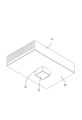
- FIG. 1 is a perspective view of a data relay device according to a first embodiment.
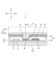
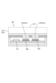
- FIG. 2 is a cross-sectional view of the data relay device.
- FIG. 3 is a perspective view of the circuit board.
- FIG. 4 is a perspective view of the heat dissipation member as viewed from below.
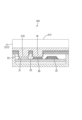
- FIG. 5 is a cross-sectional view of a data relay device according to the second embodiment.
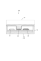
- FIG. 6 is a cross-sectional view of a data relay device according to the third embodiment.
- FIG. 7 is a cross-sectional view of an in-vehicle electronic device according to a comparative example.
- the in-vehicle electronic device comprises a housing, a circuit board housed in the housing, the circuit board having a flash memory and a first electronic component that generates more heat than the flash memory soldered thereto, and a metal heat dissipation member having a heat dissipation portion spaced apart from the circuit board and a first extension portion extending from the heat dissipation portion and in contact with the first electronic component, wherein the flash memory is not in contact with the heat dissipation member.
- In-vehicle electronic device 401 according to the comparative example has a metal heat dissipation member 412.
- Heat dissipation member 412 has a heat dissipation section 417 arranged at a distance from circuit board 411, and an extension section 418 extending from heat dissipation section 417 and in contact with electronic component 430.
- Electronic component 430 is a component that generates more heat than flash memory 432.
- extension section 418 further extends from heat dissipation section 417 toward flash memory 432, and extension section 418 contacts flash memory 432.
- the heat from the electronic component 430 and the heat from the flash memory 432 are averaged by the heat dissipation member 412.
- the heat dissipation member 412. by sharing the temperature burden between the electronic component 430 and the flash memory 432, it is possible to prevent the temperature of the electronic component 430 from rising significantly. In this case, there is an issue that the temperature of the electronic component 430 falls, but the temperature of the flash memory 432 rises.
- the first electronic component contacts the heat dissipation member via the first extension portion, while the flash memory does not contact the heat dissipation member.
- This makes it possible to suppress the temperature rise of the flash memory compared to when the first electronic component and the flash memory are in contact with the heat dissipation member to equalize the temperature.
- This makes it possible to extend the life of the flash memory soldered to the circuit board of the in-vehicle electronic device while suppressing increases in cost and space.
- the flash memory may be covered with a sheet-like insulating material.
- the flash memory is covered with a sheet-like insulating material, so that the temperature of the flash memory can be prevented from increasing due to radiant heat from the first extension portion.
- a sheet-like insulating material may be wrapped around the outer peripheral surface of the first extension portion.
- the temperature of the flash memory may increase due to radiant heat from the first extension.
- the in-vehicle electronic device described in (3) above since the outer peripheral surface of the first extension portion is wrapped with a heat insulating material, it is possible to suppress an increase in temperature of the flash memory due to radiant heat from the first extension portion.
- a sheet-shaped insulating material may be disposed between the heat dissipation section and the circuit board.
- the heat from the heat dissipation section will cause the temperature inside the housing to rise, which may in turn cause the temperature of the flash memory to rise.
- the temperature inside the housing is less likely to rise, which makes it possible to further suppress the temperature rise of the flash memory.
- the first electronic component may be an integrated circuit for arithmetic processing.
- an integrated circuit (IC) for arithmetic processing becomes hot.
- the integrated circuit for arithmetic processing is in contact with the heat dissipation member, whereas the flash memory is not in contact with the heat dissipation member, so that the temperature rise of the flash memory can be suppressed.
- the integrated circuit for arithmetic processing may be an integrated circuit for Ethernet communication that performs arithmetic processing for Ethernet communication.
- integrated circuits used for Ethernet communication become very hot.
- the integrated circuit for Ethernet communication is in contact with the heat dissipation member, whereas the flash memory is not in contact with the heat dissipation member, so that the temperature rise of the flash memory can be suppressed.
- a second electronic component that generates less heat than the first electronic component is soldered to the circuit board, and the heat dissipation member may have a second extension portion extending from the heat dissipation portion and in contact with the second electronic component.
- the second electronic component which generates less heat than the first electronic component, is in contact with the heat dissipation member via the second extension portion, so that the temperature is equalized between the first electronic component and the second electronic component, thereby preventing the temperature of the first electronic component from rising significantly.
- a data relay device 1 as an in-vehicle electronic device according to the first embodiment will be described with reference to Fig. 1.
- the data relay device 1 is a device that relays data between a plurality of in-vehicle networks having different communication protocols.
- the data relay device 1 is called, for example, a CGW-ECU (Central Gateway - Electronic Control Unit).
- Examples of the multiple in-vehicle networks include a Controller Area Network (CAN), a Local Interconnect Network (LIN), an in-vehicle Ethernet, etc. At least an in-vehicle Ethernet is connected to the data relay device 1 according to the first embodiment.
- CAN Controller Area Network
- LIN Local Interconnect Network
- Ethernet At least an in-vehicle Ethernet is connected to the data relay device 1 according to the first embodiment.
- the data relay device 1 is generally box-shaped. As shown in Fig. 2, the data relay device 1 includes a housing 10, a circuit board 11 housed in the housing 10, and a heat dissipation member 12.
- the housing 10 is made of resin and has a box-shaped case portion 13 that is open at the top, and a lid portion 14 that is fixed to the top of the case portion 13.
- the case portion 13 has a bottom wall portion 15 that is rectangular when viewed from above, and a side wall portion 16 that rises in an annular shape from the outer periphery of the bottom wall portion 15.
- circuit board 11 An example of the circuit board 11 will be described with reference to Figures 2 and 3. As shown in Figure 2, the circuit board 11 is housed in the housing 10 in a position parallel to the bottom wall portion 15. As shown in Figure 3, a CPU 30, a RAM (random access memory) 31, and a flash memory 32 are mounted by soldering on the upper surface of the circuit board 11. Other components are also mounted on the circuit board 11, but these are omitted.
- the CPU 30 is an example of a first electronic component that generates more heat than a flash memory, an integrated circuit for arithmetic processing, and an integrated circuit for Ethernet communication.
- the RAM 31 is an example of a second electronic component that generates less heat than the first electronic component.
- the CPU 30 is a CPU for Ethernet communication that performs calculation processing for Ethernet communication.
- in-vehicle Ethernet has a high communication speed, so the CPU 30 for Ethernet communication has a large amount of calculation processing per unit time. Therefore, the CPU 30 for Ethernet communication generally generates more heat than the flash memory 32.
- the RAM 31 is a main storage device for the CPU 30 to execute various programs.
- Flash memory 32 is a rewritable non-volatile semiconductor memory. Various programs and data executed by CPU 30 are stored in flash memory 32. Examples of flash memory 32 include NAND type flash ROM and NOR type flash ROM. NAND type flash ROM also includes eMMC (embedded Multi Media Card).
- eMMC embedded Multi Media Card
- the heat dissipation member 12 will be described with reference to Figure 2.
- the heat dissipation member 12 is fixed to the lid portion 14 of the housing 10 with screws, bolts, etc.
- the heat dissipation member 12 is made of a metal such as aluminum or copper, and has a heat dissipation portion 17 that is spaced apart from the circuit board 11, and a first extension portion 18 that extends from the heat dissipation portion 17.
- the heat dissipation portion 17 has a flat board portion 19 and a plurality of heat dissipation fins 20 that are formed integrally with the board portion 19.
- the multiple heat dissipation fins 20 rise parallel to one another from the upper surface of the board portion 19.
- the first extension 18 is provided at a position overlapping the CPU 30 when viewed from above.
- an opening 21 is formed in the lid 14 of the housing 10 at a position corresponding to the first extension 18.
- the first extension 18 passes through the opening 21 in the lid 14 and is inserted into the inside of the housing 10, with its bottom surface in contact with the top surface of the CPU 30. Therefore, heat from the CPU 30 is transferred to the heat dissipation section 17 via the first extension 18.
- a sheet-like insulating material 22 is wrapped around the outer peripheral surface of the first extension portion 18.
- the insulating material 22 is, for example, flexible aerogel.
- the sheet-like insulating material 22 is not limited to flexible aerogel, and can be selected as appropriate as long as it has insulating properties.
- a sheet-like insulating material 23 is disposed between the heat dissipation section 17 and the circuit board 11.
- the insulating material 23 is attached to the underside of the substrate section 19 of the heat dissipation section 17 (specifically, the portion of the underside of the substrate section 19 where the first extension section 18 is not formed).
- the insulating material 23 may be attached to the upper surface of the lid section 14 instead of the underside of the substrate section 19.
- the insulating material 23 may not be attached to either the underside of the substrate section 19 or the upper surface of the lid section 14, but may simply be sandwiched between the underside of the substrate section 19 and the upper surface of the lid section 14.
- the insulating material 22 wrapped around the first extension section 18 and the insulating material 23 attached to the underside of the substrate section 19 may be of different types.
- the heat dissipation section 17 does not have an extension provided at a position overlapping the flash memory 32 when viewed from above. Therefore, the flash memory 32 is not in contact with the heat dissipation member 12 . 2 and 3, the flash memory 32 is covered from above with a sheet-shaped insulating material 24. When viewed from above, the insulating material 24 has a shape that is slightly larger than the shape of the flash memory 32. The type of the insulating material 24 may also be different from the insulating materials 22 and 23.
- the CPU 30 contacts the heat dissipation member 12 via the first extension portion 18, while the flash memory 32 does not contact the heat dissipation member 12, so that it is possible to suppress an increase in temperature of the flash memory 32 compared to a case where the CPU 30 and the flash memory 32 are brought into contact with the heat dissipation member 12 to equalize the temperature. Therefore, it is possible to extend the life of the flash memory 32 soldered to the circuit board 11 provided in the data relay device 1 while suppressing increases in cost and space.
- the flash memory 32 is covered with the sheet-like insulating material 24, so that the temperature of the flash memory 32 can be prevented from increasing due to radiant heat from the first extension section 18.
- the insulating material 22 is wrapped around the outer peripheral surface of the first extension portion 18, so that the temperature of the flash memory 32 can be prevented from increasing due to radiant heat from the first extension portion 18.
- the sheet-like insulating material 23 is disposed between the heat dissipation section 17 and the circuit board 11, so the temperature inside the housing 10 is less likely to rise. This makes it possible to further suppress the rise in temperature of the flash memory 32.
- the first electronic component that generates more heat than the flash memory 32 is the CPU 30.
- the CPU 30 is in contact with the heat dissipation member 12, whereas the flash memory 32 is not in contact with the heat dissipation member 12, so that the rise in temperature of the flash memory 32 can be suppressed.
- the CPU 30 is a CPU for Ethernet communication. According to the data relay device 1, the CPU 30 for Ethernet communication is in contact with the heat dissipation member 12, while the flash memory 32 is not in contact with the heat dissipation member 12, so that the temperature rise of the flash memory 32 can be suppressed.
- a data relay device 201 according to the second embodiment will be described with reference to Fig. 5.
- the heat dissipation member 212 of the data relay device 201 has a second extension 218 extending from the heat dissipation section 17.
- the lower surface of the second extension 218 is in contact with the RAM 31.
- a sheet-like heat insulating material 22 is also wrapped around the outer peripheral surface of the second extension 218.
- the data relay device 201 according to the second embodiment is substantially the same as the data relay device 1 according to the first embodiment in other respects.
- the RAM 31, which generates less heat than the CPU 30, is in contact with the second extension 218, and the temperature is equalized between the CPU 30 and the RAM 31, thereby preventing the temperature of the CPU 30 from rising significantly.
- the lifespan of the RAM 31 is unlikely to be shortened even if it becomes hot, so even if the temperature of the RAM 31 rises due to the equalization, the lifespan of the RAM 31 is unlikely to be shortened.
- a data relay device 301 according to the third embodiment will be described with reference to Fig. 6.
- the data relay device 301 does not include the cover portion 14 of the first embodiment.
- the data relay device 301 according to the third embodiment is substantially the same as the data relay device 1 according to the first embodiment in other respects.
- the data relay device 1 according to the third embodiment does not have a cover portion 14, so the configuration of the data relay device 1 can be simplified.
- the data relay device 1 (CGW-ECU) is used as an example of an in-vehicle electronic device, but the in-vehicle electronic device is not limited to this.
- the in-vehicle electronic device may be an ECU for engine control, an ECU for gear shift control, or an ECU for brake control.
- the in-vehicle electronic device may be an electronic device other than an ECU.
- the CPU 30 is exemplified as an integrated circuit for arithmetic processing, but the integrated circuit for arithmetic processing may be an FPGA (Field Programmable Gate Array), an ASIC (Application Specific Integrated Circuit), or a microcomputer (so-called microcomputer).
- a microcomputer is an integrated circuit in which a CPU, RAM, flash memory, etc. are integrated into a single chip. Since the flash memory of a microcomputer generally has a small capacity, a large-capacity flash memory is often mounted on the circuit board 11 separately from the microcomputer. In this case, the microcomputer is brought into contact with the heat dissipation member 12, while the flash memory mounted separately from the microcomputer is not brought into contact with the heat dissipation member 12, thereby extending the life of the flash memory mounted separately from the microcomputer.
- the underside of the first extension portion 18 is in direct contact with the CPU 30.
- the underside of the first extension portion 18 may be indirectly in contact with the CPU 30 via a thermal pad, thermally conductive grease, a thermally conductive adhesive (e.g., a thermally conductive two-part adhesive), etc.
- the heat dissipation section 17 has a substrate section 19 and a plurality of heat dissipation fins 20, but the heat dissipation section 17 does not have to have the heat dissipation fins 20.
- the heat dissipation section 17 may be composed of only the substrate section 19.
- the housing 10 is made of resin, but the housing 10 may be made of metal.
- the RAM 31 is exemplified as the second electronic component, but the second electronic component is not limited to the RAM 31 as long as it is an electronic component that generates less heat than the first electronic component.
- the second electronic component may be a power supply IC or a FET (Field Effect Transistor).
- first extension portion 18 and the second extension portion 218 extend straight toward the circuit board 11, but they may extend while bending.
- Data relay device (an example of an in-vehicle electronic device) 10: Housing 11: Circuit board 12: Heat dissipation member 13: Case portion 14: Lid portion 15: Bottom wall portion 16: Side wall portion 17: Heat dissipation portion 18: First extension portion 19: Substrate portion 20: Heat dissipation fins 21: Opening 22: Heat insulating material 23: Heat insulating material 24: Heat insulating material 30: CPU (an example of a first electronic component, an integrated circuit for arithmetic processing, and an integrated circuit for Ethernet communication) 31: RAM (an example of a second electronic component) 32: Flash memory 201: Data relay device 212: Heat dissipation member 218: Second extension portion 301: Data relay device 401: Vehicle-mounted electronic device 411: Circuit board 412: Heat dissipation member 417: Heat dissipation portion 418: Extension portion 430: Electronic component 432: Flash memory
Landscapes
- Physics & Mathematics (AREA)
- Thermal Sciences (AREA)
- Engineering & Computer Science (AREA)
- Microelectronics & Electronic Packaging (AREA)
- Cooling Or The Like Of Electrical Apparatus (AREA)
- Cooling Or The Like Of Semiconductors Or Solid State Devices (AREA)
Abstract
Un dispositif électronique embarqué selon la présente divulgation comprend : un boîtier 10 ; une carte de circuit imprimé 11 qui est logée dans le boîtier 10 et à laquelle une mémoire flash 32 et un premier composant électronique qui génère plus de chaleur que la mémoire flash 32 sont soudés ; et un élément de dissipation de chaleur 12 qui est constitué de métal et a une partie de dissipation de chaleur 17 qui est séparée de la carte de circuit imprimé 11, et une première partie d'extension 18 qui s'étend à partir de la partie de dissipation de chaleur 17 et entre en contact avec le premier composant électronique. À l'intérieur du dispositif électronique embarqué, la mémoire flash 32 n'entre pas en contact avec l'élément de dissipation de chaleur 12.
Applications Claiming Priority (2)
| Application Number | Priority Date | Filing Date | Title |
|---|---|---|---|
| JP2023094597A JP2024176215A (ja) | 2023-06-08 | 2023-06-08 | 車載用電子機器 |
| JP2023-094597 | 2023-06-08 |
Publications (1)
| Publication Number | Publication Date |
|---|---|
| WO2024252942A1 true WO2024252942A1 (fr) | 2024-12-12 |
Family
ID=93795871
Family Applications (1)
| Application Number | Title | Priority Date | Filing Date |
|---|---|---|---|
| PCT/JP2024/019005 Ceased WO2024252942A1 (fr) | 2023-06-08 | 2024-05-23 | Dispositif électronique embarqué |
Country Status (2)
| Country | Link |
|---|---|
| JP (1) | JP2024176215A (fr) |
| WO (1) | WO2024252942A1 (fr) |
Citations (6)
| Publication number | Priority date | Publication date | Assignee | Title |
|---|---|---|---|---|
| JP2005150249A (ja) * | 2003-11-12 | 2005-06-09 | Otsuka Denki Kk | 熱伝導部材とそれを用いた放熱用構造体 |
| JP2006269685A (ja) * | 2005-03-23 | 2006-10-05 | Fujitsu Ltd | 受熱シート、電子機器及び受熱シートの製造方法 |
| JP2013254791A (ja) * | 2012-06-05 | 2013-12-19 | Nec Corp | 放熱機構およびその放熱機構を備えた電子機器 |
| US20140022733A1 (en) * | 2012-07-19 | 2014-01-23 | Samsung Electronics Co., Ltd. | Storage Device |
| JP2019075507A (ja) * | 2017-10-18 | 2019-05-16 | 日本碍子株式会社 | 放熱部材、放熱構造及び電子機器 |
| JP2022070415A (ja) * | 2020-10-27 | 2022-05-13 | 日立Astemo株式会社 | 電子制御装置 |
-
2023
- 2023-06-08 JP JP2023094597A patent/JP2024176215A/ja active Pending
-
2024
- 2024-05-23 WO PCT/JP2024/019005 patent/WO2024252942A1/fr not_active Ceased
Patent Citations (6)
| Publication number | Priority date | Publication date | Assignee | Title |
|---|---|---|---|---|
| JP2005150249A (ja) * | 2003-11-12 | 2005-06-09 | Otsuka Denki Kk | 熱伝導部材とそれを用いた放熱用構造体 |
| JP2006269685A (ja) * | 2005-03-23 | 2006-10-05 | Fujitsu Ltd | 受熱シート、電子機器及び受熱シートの製造方法 |
| JP2013254791A (ja) * | 2012-06-05 | 2013-12-19 | Nec Corp | 放熱機構およびその放熱機構を備えた電子機器 |
| US20140022733A1 (en) * | 2012-07-19 | 2014-01-23 | Samsung Electronics Co., Ltd. | Storage Device |
| JP2019075507A (ja) * | 2017-10-18 | 2019-05-16 | 日本碍子株式会社 | 放熱部材、放熱構造及び電子機器 |
| JP2022070415A (ja) * | 2020-10-27 | 2022-05-13 | 日立Astemo株式会社 | 電子制御装置 |
Also Published As
| Publication number | Publication date |
|---|---|
| JP2024176215A (ja) | 2024-12-19 |
Similar Documents
| Publication | Publication Date | Title |
|---|---|---|
| JP4877389B2 (ja) | 自動変速機用コントロールユニット冷却装置 | |
| JP4735528B2 (ja) | 車載用の電子機器の冷却構造 | |
| JP2006303106A (ja) | 電子回路装置 | |
| JP4023054B2 (ja) | 電子回路ユニット | |
| JP7618399B2 (ja) | 電子機器の温度調整構造 | |
| CN105493648B (zh) | 车辆用电子控制装置 | |
| WO2022110741A1 (fr) | Dispositif électronique doté d'une structure de support flottante | |
| JP4387314B2 (ja) | 電気接続箱 | |
| JP6982776B2 (ja) | 発熱電子部品の放熱装置、車載充電器、および車両 | |
| CN211128747U (zh) | 排热结构及电子设备 | |
| JP2024176215A (ja) | 車載用電子機器 | |
| CN104080312A (zh) | 车辆用电子控制装置 | |
| US11848251B2 (en) | Semiconductor device | |
| JP6424839B2 (ja) | 電子制御ユニット、および、これを用いた電動パワーステアリング装置 | |
| JP4851154B2 (ja) | 回路基板内蔵筐体 | |
| JP7746804B2 (ja) | 演算ユニットの冷却構造 | |
| KR20200025215A (ko) | 전자제어 장치 | |
| KR101063172B1 (ko) | 전자제어장치 | |
| JP2003188563A (ja) | 電子制御装置 | |
| JP2007216823A (ja) | 車載制御装置のケース収容構造 | |
| JP2021190495A (ja) | 電子制御装置 | |
| JP2010163018A (ja) | 車両用の冷却装置 | |
| JP7619156B2 (ja) | 電子制御装置 | |
| WO2025215971A1 (fr) | Unité de connexion électrique | |
| WO2025135118A1 (fr) | Structure de boîtier de dispositif électronique |
Legal Events
| Date | Code | Title | Description |
|---|---|---|---|
| 121 | Ep: the epo has been informed by wipo that ep was designated in this application |
Ref document number: 24819174 Country of ref document: EP Kind code of ref document: A1 |
|
| NENP | Non-entry into the national phase |
Ref country code: DE |
|
| 122 | Ep: pct application non-entry in european phase |
Ref document number: 24819174 Country of ref document: EP Kind code of ref document: A1 |