WO2024252960A1 - Connecteur - Google Patents
Connecteur Download PDFInfo
- Publication number
- WO2024252960A1 WO2024252960A1 PCT/JP2024/019259 JP2024019259W WO2024252960A1 WO 2024252960 A1 WO2024252960 A1 WO 2024252960A1 JP 2024019259 W JP2024019259 W JP 2024019259W WO 2024252960 A1 WO2024252960 A1 WO 2024252960A1
- Authority
- WO
- WIPO (PCT)
- Prior art keywords
- housing
- exposed
- insulating
- connector
- receiving
- Prior art date
- Legal status (The legal status is an assumption and is not a legal conclusion. Google has not performed a legal analysis and makes no representation as to the accuracy of the status listed.)
- Ceased
Links
Images



Classifications
-
- H—ELECTRICITY
- H01—ELECTRIC ELEMENTS
- H01R—ELECTRICALLY-CONDUCTIVE CONNECTIONS; STRUCTURAL ASSOCIATIONS OF A PLURALITY OF MUTUALLY-INSULATED ELECTRICAL CONNECTING ELEMENTS; COUPLING DEVICES; CURRENT COLLECTORS
- H01R13/00—Details of coupling devices of the kinds covered by groups H01R12/70 or H01R24/00 - H01R33/00
- H01R13/56—Means for preventing chafing or fracture of flexible leads at outlet from coupling part
Definitions
- This disclosure relates to connectors.
- Patent Document 1 discloses a terminal fitting that includes a connection member called a terminal body and a slide member that is attached to the connection member.
- the terminal fitting is accommodated in a housing.
- An exposed conductor (core wire) that is exposed from the coating at the front end of the electric wire is inserted into the connection member.
- the slide member is capable of sliding relative to the connection member between a spaced position where the exposed conductor is separated from the contact portion (contact surface) of the connection member and a connection position where the exposed conductor is in contact with the contact portion.
- the terminal fitting is accommodated in the housing and a jig is placed against the rear surface of the housing.
- the exposed conductor of the electric wire is inserted from the slide member into the connection member while being guided by a guide portion formed on the jig.
- the jig is removed and the slide member is pushed from the separated position to the connection position. This makes the exposed conductor of the electric wire available for contact with the contact portion of the connection member.
- Patent Document 2 discloses a structure including a plurality of electric wires having bent portions, an electric wire cover that holds the bent portions, and a cylindrical member that is attached to the electric wire cover. Each electric wire is inserted from the electric wire cover to the cylindrical member.
- Patent Document 2 discloses a structure including a wire cover, a corrugated tube attached to the wire cover, and a plurality of wires inserted from the wire cover to the corrugated tube.
- the present disclosure therefore aims to provide a connector that can improve electrical reliability.
- the connector disclosed herein comprises a plurality of electric wires having exposed conductors exposed forward from the covering, a plurality of terminal fittings connected to the plurality of exposed conductors, and a housing that accommodates the plurality of terminal fittings, some of the exposed conductors being disposed at the rear of the housing, and further comprises an insulating member interposed between adjacent portions of the exposed conductors at the rear of the housing.
- This disclosure provides a connector that can improve electrical reliability.
- FIG. 1 is an exploded perspective view of each member, excluding wiring members, in a connector according to a first embodiment.
- FIG. 2 is a perspective view of the connector of the first embodiment.
- FIG. 3 is a rear view of the connector of the first embodiment.
- FIG. 4 is a plan view of the wiring member in the connector of the first embodiment.
- FIG. 5 is a side view of a terminal fitting in the connector of the first embodiment.
- Figure 6 is an oblique view showing a state in which a terminal fitting is accommodated in the first accommodating chamber of the first member, the exposed conductor of the first wiring member is connected to the accommodated terminal fitting, and an insulating member is positioned above in the connector of embodiment 1.
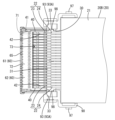
- FIG. 7 is a plan view showing a state in which the insulating member is attached to the receiving member from the state shown in FIG. 6 in the connector of the first embodiment, and the exposed conductor of the first wiring member is covered with the insulating member.
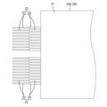
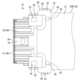
- Figure 8 is a plan view showing a state in which a terminal fitting is accommodated in the second accommodating chamber of the second member from the state shown in Figure 7 in the connector of embodiment 1, and an exposed conductor of the second wiring member is connected to the accommodated terminal fitting.
- 9 is a plan view showing a state in which a third member is attached to the connector shown in FIG. 8 in the first embodiment.
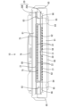
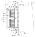
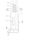
- FIG. 10 is a side view showing a state in which an insulating member is interposed between exposed conductors of the first wiring member and the second wiring member in the connector of the first embodiment, with the insulating member cut away.
- the connector of the present disclosure comprises: (1) A terminal assembly comprising a plurality of electric wires each having an exposed conductor exposed forward from a covering, a plurality of terminal fittings connected to the exposed conductors, and a housing accommodating the plurality of terminal fittings, wherein a portion of the exposed conductors is disposed at the rear of the housing, and further comprising an insulating member interposed between adjacent portions of the exposed conductors at the rear of the housing.
- the above configuration (1) can prevent contact between adjacent exposed conductors at the rear of the housing by using an insulating member. As a result, the electrical reliability of the connector can be improved.
- the rear of the housing means the area behind the rear surface of the housing.
- the insulating member is an elastically deformable member.
- the insulating member is an elastically deformable member, it can accommodate variations in the distance between parts of the exposed conductor. For example, one insulating member can accommodate multiple types of electric wires with different wire diameters. Furthermore, it is possible to realize a state in which the insulating member comes into contact with each of the adjacent electric wires.
- the connector further includes a cover member connected to the housing and covering a portion of the exposed conductor, and the insulating member is held by the cover member.
- the above configuration (3) can protect a portion of the exposed conductor by covering it with a cover member.
- the cover member can also have the function of holding the insulating member.
- the insulating member is arranged at the rear of the housing between some of the exposed conductors that are adjacent in the height direction and arranged side by side in the width direction, with the insulating member being arranged in a shape that extends entirely in the width direction.
- the insulating member is arranged so that it extends in the width direction overall between parts of the exposed conductors that are adjacent in the height direction, making it possible to simplify the overall shape of the insulating member and make it compact.
- the terminal metal fitting comprises a connection member into which the exposed conductor is inserted, and a slide member that is attached to the connection member so as to be slidable between a spaced position in which the exposed conductor does not contact the connection member and a connection position in which the exposed conductor contacts the connection member.
- the exposed conductor When the slide member is in the separated position, the exposed conductor is inserted into the connection member from the rear of the housing through the slide member. If a structure were provided to guide the exposed conductor to the rear of the housing when inserting the exposed conductor into the connection member, there would be a concern that part of the exposed conductor would remain exposed at the rear of the housing. In contrast, with this configuration, contact between adjacent parts of the exposed conductor can be prevented by the insulating member, effectively preventing the occurrence of short circuits and leaks.
- the connector 10 of the first embodiment includes a wiring member 20 including a plurality of electric wires 22, a plurality of terminal fittings 40 connected to the electric wires 22, a housing 60 accommodating the terminal fittings 40, an insulating member 30 disposed behind the housing 60, and cover members 80, 90 surrounding the insulating member 30.
- the cover member is composed of a holding member 80 and a receiving member 90.
- the front side is defined as the side where the connector 10 is mated with a mating connector (not shown).
- the up-down direction is based on the up-down direction in Figs. 1 and 2.
- the arrows X, Y, and Z represent the front, right, and up, respectively. These directions do not necessarily coincide with the directional reference when the connector 10 is mounted on a vehicle (not shown) or the like.
- the wiring member 20 has a sheet portion 21 and a plurality of electric wires 22 fixed to the sheet portion 21.
- the sheet portion 21 is made of an insulating material, for example, a nonwoven fabric.
- An example of the electric wires 22 is a coated electric wire in which an outer periphery of a conductor 23, such as a core wire, is covered with an insulating coating 24.
- the multiple electric wires 22 are fixed to one surface of the sheet portion 21 (the lower surface in the case of this embodiment 1) in a state lined up in the left-right direction.
- Each electric wire 22 is fixed to one surface of the sheet portion 21 by, for example, a welding means.
- a welding means a known welding means such as ultrasonic welding, heat and pressure welding, high frequency welding, etc. can be used.
- the wiring member 20 is flexible overall, has a reduced height dimension, and has a flat rectangular shape in a plan view.
- each electric wire 22 is disposed so as to protrude forward from the sheet portion 21.
- the front end of each electric wire 22 has the conductor 23 exposed by stripping off the coating 24 (hereinafter, the conductor exposed at the front end of each electric wire 22 is referred to as the "exposed conductor 23").
- the wiring member 20 has a first wiring member 20A arranged in the lower stage inside the connector 10 and a second wiring member 20B arranged in the upper stage.
- the number of each electric wire 22 fixed to the sheet portion 21 differs between the first wiring member 20A and the second wiring member 20B.
- the first wiring member 20A includes a portion in the left-right center portion of the sheet portion 21 where the electric wires 22 are not fixed, and accordingly, the number of each electric wire 22 is fewer than that of the second wiring member 20B.
- the number of each electric wire 22 may be the same in the first wiring member 20A and the second wiring member 20B, or, conversely, the first wiring member 20A may have more electric wires than the second wiring member 20B.
- the terminal fitting 40 includes a connection member 41 and a slide member 42 that is slidably attached to the connection member 41 between a spaced position and a connected position.
- the connection member 41 and the slide member 42 are separate from each other. Both the connection member 41 and the slide member 42 are formed by bending a conductive metal plate or the like.
- connection member 41 has a cylindrical, for example, rectangular, connection body 43.
- the connection body 43 receives a mating terminal fitting (not shown) from the front and is electrically connected.
- the connection member 41 also has a contact portion (not shown) that extends rearward from the connection body 43.
- the slide member 42 has a cylindrical, for example, square cylindrical, box portion 45.
- the contact portion of the connection member 41 is inserted into the box portion 45.
- the slide member 42 has a pressing portion (not shown) inside the box portion 45.
- the housing 60 is composed of a first member 61, a second member 62, and a third member 63.
- the first member 61, the second member 62, and the third member 63 are arranged in this order in a stacked state from the bottom up.
- the first member 61, the second member 62, and the third member 63 are all made of synthetic resin.
- the first member 61 is configured as a lower housing.
- the first member 61 is rectangular in plan view and elongated in the left-right direction.
- the first member 61 has a plurality of first accommodating chambers 64 arranged in a row in the left-right direction on the upper surface side.
- Each first accommodating chamber 64 extends in the front-rear direction in the first member 61 and opens to the rear.
- the terminal fittings 40 are inserted from the rear into the first accommodating chambers 64 and accommodated therein.
- the first member 61 has a front wall 65 that constitutes the front portion of the housing 60.
- the front wall 65 has a plurality of terminal insertion holes 66 that communicate with the front openings of each of the first accommodating chambers 64 and each of the second accommodating chambers 71 described later.
- the terminal insertion holes 66 are arranged in two rows, one above the other, and open in a row in the left-right direction.
- the mating terminal fittings (not shown) are connected to the terminal fittings 40 from the front of the housing 60 through the terminal insertion holes 66.
- the first member 61 has a flat first cover portion 67 that closes the upper surface of the front part of each first storage chamber 64.
- the connection member 41 of the terminal fitting 40 is accommodated in the front part of the first storage chamber 64, and the first cover portion 67 prevents the connection member 41 from slipping out upward.
- the first member 61 has a first exposed surface 68 that opens the upper surface of the rear part of each first storage chamber 64.
- the slide member 42 of the terminal fitting 40 is accommodated in the rear part of the first storage chamber 64, and is exposed upward by the first exposed surface 68. When a part of the slide member 42 exposed on the first exposed surface 68 (see the protrusion 47 in FIG. 5) is pressed forward, the slide member 42 is moved from the separated position to the connected position.
- the first member 61 has a pair of first housing lock portions 69 that protrude upward at both left and right ends.
- the second member 62 is configured as an inner housing. As shown in FIG. 1 and FIG. 8, the second member 62 has a rectangular shape in a plan view that is slightly smaller than the first member 61, and is formed long in the left-right direction. The lower surface of the second member 62 covers the upper surface of the first member 61 and closes the first exposed surface 68.
- the second member 62 has a plurality of second accommodating chambers 71 arranged in a row in the left-right direction on the upper surface side. Each second accommodating chamber 71 extends in the front-rear direction in the second member 62 and is open to the rear.
- the terminal fitting 40 is inserted from the rear into the second accommodating chamber 71 and accommodated therein.
- the second member 62 has a flat second cover portion 72 that closes the upper surface of the front part of each second accommodating chamber 71, and has a second exposed surface 73 that opens the upper surface of the rear part of each second accommodating chamber 71.
- the functions of the second cover portion 72 and the second exposed surface 73 are similar to those of the first cover portion 67 and the first exposed surface 68 described above.
- the second member 62 has a pair of second housing locking parts 74 at both the left and right ends. Each second housing locking part 74 is engaged with each first housing locking part 69 from the inside, thereby holding the second member 62 to the first member 61 (see FIG. 10).
- the third member 63 is configured as an upper housing. As shown in FIG. 1 and FIG. 9, the third member 63 is rectangular in plan view, slightly larger than the first member 61, and is formed long in the left-right direction. The lower surface of the third member 63 covers the upper surface of the second member 62 and closes the second exposed surface 73.
- the third member 63 has a plurality of housing grooves 75 (see FIG. 3) connected to the rear end of the lower surface.
- the housing grooves 75 are arranged in a row in the left-right direction at positions corresponding to the second storage chambers 71.
- the housing grooves 75 have a U-shaped cross section and open downward.
- the housing grooves 75 are arranged behind the first member 61 and the second member 62.
- the electric wires 22 of the second wiring member 20B are inserted into the housing grooves 75 from below.
- the third member 63 has an elastically deformable lock arm 76 at the left and right center of the upper surface.
- the lock arm 76 locks the mating connector and holds the connector 10 and the mating connector in a mated state.
- the third member 63 has a pair of third housing locking portions 77 protruding downward at both left and right ends. Each third housing locking portion 77 is engaged with each first housing locking portion 69 from the outside, thereby holding the third member 63 in a stacked state with respect to the first member 61 and the second member 62 (see Figures 1 and 2).
- the third member 63 has a pair of locking portions 78 at both left and right ends and at the rear end behind each third housing locking portion 77.
- Each locking portion 78 has a rectangular column shape extending in the vertical direction.
- each locking portion 78 is located behind each of the first member 61 and the second member 62.
- the third member 63 and therefore the housing 60 are held (connected) to the holding member 80 and the receiving member 90.
- the receiving member 90 is configured as a lower cover.
- the receiving member 90 is made of synthetic resin, has a rectangular shape in a plan view, and is formed long in the left-right direction.
- the receiving member 90 is arranged in line with the first member 61 behind the first member 61.
- the receiving member 90 has a flat receiving body 91.
- the receiving member 90 has a plurality of cover grooves 92 connected to the front end of the receiving body 91.
- the cover grooves 92 are arranged in a row in the left-right direction at positions corresponding to the first storage chambers 64.
- the cover grooves 92 have a U-shaped cross section and open upward.
- the electric wires 22 of the first wiring member 20A are inserted into the cover grooves 92 from above.
- the cover grooves 92 and the housing grooves 75 are misaligned with each other in the width direction.
- the receiving member 90 has a pair of first receiving portions 93 at the front end of the receiving body 91, on both the left and right ends sandwiching each cover groove portion 92.
- Each first receiving portion 93 has a rectangular concave cross section and is open upward. The lower portion of each locking portion 78 is fitted into each first receiving portion 93 from above in a positioned state.
- each first receiving portion 93 has front, rear, left and right wall portions that define a fitting space 93A into which each locking portion 78 fits, and has an end positioning portion 98 on one of the left and right wall portions located toward the left and right center of the receiving body 91.
- the end positioning portion 98 is formed by cutting out one of the left and right wall portions of the first receiving portion 93, and is open upward.
- the end positioning portion 98 is in communication with the fitting space 93A.
- the receiving member 90 has a central positioning portion 99 at the front end of the receiving body 91 and at the center of the left and right sides.
- the central positioning portion 99 protrudes upward like a rib from a stage portion 99A that protrudes from the receiving body 91.
- the cover groove portions 92 are respectively disposed on both the left and right sides of the stage portion 99A.
- the insulating member 30 is held in a positioned state on the receiving member 90 by each end positioning portion 98 and the central positioning portion 99.
- the receiving member 90 has flat opposing surfaces 94 facing the sheet portion 21 of the wiring member 20 behind each of the cover grooves 92 and each of the first receiving portions 93 on the upper surface of the receiving body 91.
- the receiving member 90 has a pair of pin receiving portions 95 at both the left and right ends of the receiving body 91 and behind each of the first receiving portions 93.
- Each pin receiving portion 95 is a hole with a circular cross section, penetrates the receiving body 91 in the vertical direction (thickness direction), and opens on the opposing surface 94 and the lower surface of the receiving body 91.
- each pin receiving portion 95 opening on the opposing surface 94 has an edge shape without chamfering, and is configured as a scraping edge 96 that can scrape the sheet portion 21 between the hole punching pin 83 described later.
- the receiving member 90 also has a pair of first cover locking portions 97 that protrude upward from both the left and right ends of the receiving body 91.
- the holding member 80 is configured as an upper cover.
- the holding member 80 is made of synthetic resin, has a rectangular shape in a plan view, and is formed long in the left-right direction.
- the holding member 80 is arranged in parallel with the third member 63 behind the third member 63.
- the holding member 80 is arranged facing the receiving member 90 with the first wiring member 20A and the second wiring member 20B sandwiched between them.
- the holding member 80 has a flat plate-shaped holding body 81.
- the holding member 80 has a pair of second receiving portions 82 that protrude forward from both the left and right sides of the holding body 81.
- Each second receiving portion 82 has a rectangular frame shape.
- the upper portion of each locking portion 78 is fitted into each second receiving portion 82 from below in a positioned state (see FIG. 2).
- the bottom surface of the holding body 81 is formed flat.
- the holding member 80 has a pair of hole-punching pins 83 protruding from the rear of each second receiving portion 82 on both the left and right sides of the bottom surface of the holding body 81.
- Each hole-punching pin 83 is cylindrical.
- Each hole-punching pin 83 extends downward from the bottom surface of the holding body 81 and has a tapered reduced diameter portion 84 at its lower end.
- the holding member 80 has a pair of second cover locking portions 85 protruding downward from both the left and right ends of the holding body 81. Each second cover locking portion 85 is engaged with each first cover locking portion 97, thereby holding the holding member 80 in a connected state to the receiving member 90 (see FIG. 2).
- the insulating member 30 is an insulating member and has a plate shape, for example a strip shape, that is long in the left-right direction as a whole, as shown in Fig. 1.
- the insulating member 30 is a rubber material such as silicone rubber, and is elastically deformable.
- the insulating member 30 includes an insulating body 31 having a rectangular plate shape that has a certain thickness and extends in the left-right direction, a central position restricting portion 32 that penetrates a left-right central portion of the insulating body 31 in the thickness direction (up-down direction), and a pair of end position restricting portions 33 that protrude outward to the left and right from the end faces on both the left and right sides of the insulating body 31.
- the left-right length of the insulating body 31 exceeds the left-right formation range of each electric wire 22 arranged side by side in the wiring member 20.
- the front-rear width of the insulating body 31 is smaller than the front-rear separation width between the rear end of the housing 60 and the front end of the sheet portion 21 in the connector 10.
- the thickness of the insulating body 31 corresponds to the vertical separation distance between each electric wire 22 of the first wiring member 20A and each electric wire 22 of the second wiring member 20B.
- the central position regulating portion 32 has an opening shape that is long in the front-to-rear direction, and the central positioning portion 99 can be fitted inside.
- the end position regulating portion 33 has a rectangular plate shape in a plan view that is continuous with the insulating body 31 and has the same thickness as the insulating body 31, and can be fitted into the end positioning portion 98.
- the connector 10 can be automatically assembled using, for example, an automated machine.
- each terminal fitting 40 is accommodated in each first accommodation chamber 64 of the first member 61.
- the slide member 42 is arranged at a position separated from the connection member 41.
- the receiving member 90 is arranged behind the first member 61, and each electric wire 22 of the first wiring member 20A is inserted into each terminal fitting 40 from behind.
- Each electric wire 22 is positioned in the left-right direction in each cover groove portion 92 of the first member 61.
- the exposed conductor 23 of each electric wire 22 is arranged inside the terminal fitting 40 from the slide member 42 to the connection member 41. Since each electric wire 22 is fixed to the sheet portion 21 common to each electric wire 22, by moving the sheet portion 21 forward, each electric wire 22 can be inserted into each terminal fitting 40 at the same time.
- a jig (not shown) is placed behind the first member 61, and a guide portion formed on the jig can guide the insertion of the exposed conductor 23 of each electric wire 22.
- a part (rear portion) of the exposed conductor 23 is exposed and positioned behind the first member 61 (see FIG. 6).
- each terminal fitting 40 is moved to the connection position via the first exposed surface 68 (see FIG. 6). This connects each terminal fitting 40 to each electric wire 22 of the first wiring member 20A.
- each end position restricting portion 33 fits into each end positioning portion 98 from above, and the central position restricting portion 99 fits into the central position restricting portion 32 from below, thereby holding the insulating member 30 in a positioned state on the receiving member 90.
- the peripheral portion of the central position restricting portion 32 of the insulating member 30 can be supported by the stage portion 99A of the receiving member 90.
- a portion of the exposed conductor 23 of each electric wire 22 is covered and concealed by the insulating body 31 of the insulating member 30.
- each terminal metal fitting 40 is accommodated in each second accommodation chamber 71 of the second member 62, and each electric wire 22 of the second wiring member 20B is inserted into each terminal metal fitting 40.
- the slide member 42 of each terminal metal fitting 40 is moved to the connection position via the second exposed surface 73 (see FIG. 8).
- a part of the exposed conductor 23 is exposed and arranged behind the second member 62.
- the insulating body 31 of the insulating member 30 is arranged. In other words, the insulating body 31 of the insulating member 30 is arranged between each exposed conductor 23 adjacent in the vertical direction (see FIG. 10). Therefore, each exposed conductor 23 adjacent in the vertical direction is kept insulated via the insulating member 30.
- the third member 63 is attached to the first member 61 from above the second member 62 and engaged.
- the second exposed surface 73 is covered by the third member 63. This completes the assembly of the housing 60.
- the sheet portions 21 of the first wiring member 20A and the second wiring member 20B are positioned behind the housing 60 and supportable on the opposing surface 94 of the first member 61.
- each hole-punching pin 83 presses the sheet portion 21 of each of the first wiring member 20A and the second wiring member 20B against the opposing surface 94 of the receiving member 90.
- Each sheet portion 21 is sandwiched collectively between the reduced diameter portion 84 of each hole-punching pin 83 and the chamfered edge 96 of each pin receiving portion 95.
- each sheet portion 21 is chamfered by the chamfered edge 96 of each pin receiving portion 95, and at the same time, each hole-punching pin 83 penetrates each sheet portion 21.
- each sheet portion 21 is held in a vertically aligned state by each hole-punching pin 83 (see FIG. 3).
- the diameter of the hole formed in the seat portion 21 is equal to the diameter of the hole-punching pin 83 that passes through the hole.
- the exposed conductor 23 of the electric wire 22 is pressed against the pressing portion inside the connection member 41 and held against the terminal fitting 40.
- the holding force with which the terminal fitting 40 holds the exposed conductor 23 tends to be weaker than when the exposed conductor 23 is crimped by the barrel of a general terminal.
- the hole-punching pins 83 penetrate and hold the seat portion 21, so that the tensile force can be resisted. For this reason, it is possible to prevent the seat portion 21 from retreating in response to the tensile force, and the position of the seat portion 21 relative to the terminal fitting 40 can be maintained constant. As a result, the state in which each electric wire 22 of the wiring member 20 is connected to each terminal fitting 40 can be maintained.
- an insulating member 30 is interposed between parts of each exposed conductor 23 adjacent in the vertical direction at the rear of the housing 60, so that the insulating member 30 can prevent the parts of each exposed conductor 23 from contacting each other.
- the electrical reliability of the connector 10 can be improved.
- the receiving member 90 as a cover member has both the function of covering and protecting a portion of each exposed conductor 23 from below and the function of holding the insulating member 30, so that the configuration can be prevented from becoming complicated.
- the insulating member 30 of this embodiment 1 is arranged as a whole in a shape extending in the left-right direction between the portions of each exposed conductor 23 that are adjacent in the vertical direction (height direction) and arranged in a row in the left-right direction (width direction) at the rear of the housing 60. Therefore, a single insulating member 30 can be used as a member that prevents contact between the portions of each exposed conductor 23 that are arranged in a row in the vertical and left-right directions. Moreover, since the insulating member 30 is arranged in a shape extending in the left-right direction as a whole between the portions of each exposed conductor that are adjacent in the vertical direction, the overall shape of the insulating member 30 can be simplified and made compact.
- the first member 61, the second member 62, and the third member 63 are assembled in sequence from below while sandwiching the first wiring member 20A and the second wiring member 20B therebetween, and the receiving member 90, the insulating member 30, and the holding member 80 are also assembled in sequence from below. Therefore, the assembly work of the connector 10 can be efficiently performed using an automated machine or the like. Furthermore, since each hole punching pin 83 penetrates the respective sheet portions 21 of the first wiring member 20A and the second wiring member 20B collectively, the efficiency of the assembly work can be further improved.
- both the holding member and the receiving member are held (connected) separately from the housing at the rear of the housing.
- at least one of the holding member and the receiving member may be held integrally with the housing at the rear of the housing.
- the sheet portion of the wiring member is configured to be punched by the hole punching pin while being sandwiched between the hole punching pin of the holding member and the pin receiving portion of the receiving member.
- the connector may not include a receiving member, and the sheet portion of the wiring member may be configured to be punched only by the hole punching pin of the holding member.
- the wiring member is composed of the first wiring member and the second wiring member.
- the wiring member may be composed of only one of the first wiring member and the second wiring member, or may further include another wiring member in addition to the first wiring member and the second wiring member.
- an insulating member is disposed between each pair of adjacent wiring members.
- the terminal fitting is configured to be connected to the electric wire by sliding the slide member to the connecting position relative to the connecting member.
- Connector 20 Wiring member 20A: First wiring member 20B: Second wiring member 21: Sheet portion 22: Electric wire 23: Exposed conductor (conductor) 24...Covering 30...Insulating member 31...Insulating body 32...Central position restriction portion 33...End side position restriction portion 40...Terminal metal fitting 41...Connection member 42...Slide member 43...Connection body 45...Box portion 47...Protrusion 60...Housing 61...First member 62...Second member 63...Third member 64...First accommodating chamber 65...Front wall 66...Terminal insertion hole 67...First cover portion 68...First exposed surface 69...First housing lock portion 71...Second accommodating chamber 72...Second cover portion 73...Second exposed surface 74...Second housing lock portion 75...Housing groove portion 76...Lock arm 77...Third housing lock portion 78...Latching portion 80...Retaining member (cover member) 81: Re
Landscapes
- Details Of Connecting Devices For Male And Female Coupling (AREA)
- Connector Housings Or Holding Contact Members (AREA)
Abstract
Un connecteur (10) comprend : une pluralité de fils électriques (22) présentant des conducteurs exposés (23) exposés vers l'avant à partir de revêtements (24) ; une pluralité de raccords métalliques de borne (40) connectés aux conducteurs exposés (23) ; et un logement (60) qui loge la pluralité de raccords métalliques de borne (40). Des parties (parties arrière) des conducteurs exposés (23) sont agencées à l'arrière du logement (60). Un élément isolant (30) interposé entre des parties de conducteurs adjacents parmi les conducteurs exposés (23) est en outre disposé à l'arrière du logement (60).
Applications Claiming Priority (2)
| Application Number | Priority Date | Filing Date | Title |
|---|---|---|---|
| JP2023095352A JP2024176635A (ja) | 2023-06-09 | 2023-06-09 | コネクタ |
| JP2023-095352 | 2023-06-09 |
Publications (1)
| Publication Number | Publication Date |
|---|---|
| WO2024252960A1 true WO2024252960A1 (fr) | 2024-12-12 |
Family
ID=93795489
Family Applications (1)
| Application Number | Title | Priority Date | Filing Date |
|---|---|---|---|
| PCT/JP2024/019259 Ceased WO2024252960A1 (fr) | 2023-06-09 | 2024-05-24 | Connecteur |
Country Status (2)
| Country | Link |
|---|---|
| JP (1) | JP2024176635A (fr) |
| WO (1) | WO2024252960A1 (fr) |
Citations (8)
| Publication number | Priority date | Publication date | Assignee | Title |
|---|---|---|---|---|
| JP2002144368A (ja) * | 2000-11-15 | 2002-05-21 | Tokai Kogyo Co Ltd | コネクタ一体型ケースの成形方法 |
| US7147512B2 (en) * | 2005-04-19 | 2006-12-12 | Hon Hai Precision Ind. Co., Ltd. | Connector assembly |
| US20090197459A1 (en) * | 2008-02-01 | 2009-08-06 | Hon Hai Precision Ind. Co., Ltd. | Cable connector assembly having wire management members with low profile |
| US20160211093A1 (en) * | 2015-01-19 | 2016-07-21 | Eaton Corporation | Electrical system, electrical switching apparatus and guard assembly therefor |
| JP2018516442A (ja) * | 2015-06-03 | 2018-06-21 | スリーエム イノベイティブ プロパティズ カンパニー | 低プロファイル電気コネクタ |
| JP2019145208A (ja) * | 2018-02-15 | 2019-08-29 | 株式会社オートネットワーク技術研究所 | 端子、及びコネクタ |
| WO2019235389A1 (fr) * | 2018-06-05 | 2019-12-12 | 株式会社オートネットワーク技術研究所 | Connecteur de jonction |
| JP2021140977A (ja) * | 2020-03-06 | 2021-09-16 | 株式会社オートネットワーク技術研究所 | コネクタ |
-
2023
- 2023-06-09 JP JP2023095352A patent/JP2024176635A/ja active Pending
-
2024
- 2024-05-24 WO PCT/JP2024/019259 patent/WO2024252960A1/fr not_active Ceased
Patent Citations (8)
| Publication number | Priority date | Publication date | Assignee | Title |
|---|---|---|---|---|
| JP2002144368A (ja) * | 2000-11-15 | 2002-05-21 | Tokai Kogyo Co Ltd | コネクタ一体型ケースの成形方法 |
| US7147512B2 (en) * | 2005-04-19 | 2006-12-12 | Hon Hai Precision Ind. Co., Ltd. | Connector assembly |
| US20090197459A1 (en) * | 2008-02-01 | 2009-08-06 | Hon Hai Precision Ind. Co., Ltd. | Cable connector assembly having wire management members with low profile |
| US20160211093A1 (en) * | 2015-01-19 | 2016-07-21 | Eaton Corporation | Electrical system, electrical switching apparatus and guard assembly therefor |
| JP2018516442A (ja) * | 2015-06-03 | 2018-06-21 | スリーエム イノベイティブ プロパティズ カンパニー | 低プロファイル電気コネクタ |
| JP2019145208A (ja) * | 2018-02-15 | 2019-08-29 | 株式会社オートネットワーク技術研究所 | 端子、及びコネクタ |
| WO2019235389A1 (fr) * | 2018-06-05 | 2019-12-12 | 株式会社オートネットワーク技術研究所 | Connecteur de jonction |
| JP2021140977A (ja) * | 2020-03-06 | 2021-09-16 | 株式会社オートネットワーク技術研究所 | コネクタ |
Also Published As
| Publication number | Publication date |
|---|---|
| JP2024176635A (ja) | 2024-12-19 |
Similar Documents
| Publication | Publication Date | Title |
|---|---|---|
| US6692294B2 (en) | Connector | |
| CN100403604C (zh) | 同轴电缆连接器 | |
| EP3389149B1 (fr) | Connecteur électrique | |
| CN114930652B (zh) | 屏蔽连接器 | |
| JP7092259B2 (ja) | コネクタ | |
| KR20020046189A (ko) | 전기 커넥터 | |
| CN113826283A (zh) | 连接装置及连接器 | |
| JP2023077166A (ja) | シールド端子およびコネクタ | |
| JP6847016B2 (ja) | 同軸ケーブル用コネクタ | |
| JP2024177529A (ja) | コネクタ | |
| CN110870143B (zh) | 端子零件 | |
| JP7659735B2 (ja) | コネクタ | |
| US7232341B2 (en) | Connector in which a shell can be readily assembled to a connector housing | |
| CN115210959A (zh) | 连接器 | |
| JP7444131B2 (ja) | コネクタ | |
| JP7404949B2 (ja) | コネクタ、及びコネクタの製造方法 | |
| JP6768304B2 (ja) | コネクタの組立方法 | |
| WO2024252960A1 (fr) | Connecteur | |
| JP5289154B2 (ja) | コネクタ | |
| WO2024252958A1 (fr) | Connecteur | |
| WO2024252961A1 (fr) | Connecteur | |
| JP2024176631A (ja) | コネクタカバー | |
| JP6013130B2 (ja) | 圧接コネクタ及び端子装着方法 | |
| JP2023077163A (ja) | シールド端子およびコネクタ | |
| JP2002124341A (ja) | コネクタ |
Legal Events
| Date | Code | Title | Description |
|---|---|---|---|
| 121 | Ep: the epo has been informed by wipo that ep was designated in this application |
Ref document number: 24819192 Country of ref document: EP Kind code of ref document: A1 |
|
| NENP | Non-entry into the national phase |
Ref country code: DE |